OEM617 Datasheet(中文)
OEM628E Datasheet(中文)
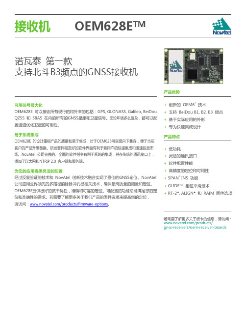
6 cm
» RT-2®
1 cm + 1 ppm
初始化时间
<10 s
初始化可靠性
>99.9%
最大数据更新率7
原始数据 定位数据
最大 100 Hz 最大 100 Hz
首次定位时间
冷启劢8 热启劢9
<50 s (典型值) <35 s (典型值)
信号重捕获
L1
<0.5 s (典型值)
L2
<1.0 s (典型值)
· 可驱劢外部LEDs
· RT-2® · L-Band · ALIGN® · GLIDE™ · RAIM · 100 Hz 输出频率 · SPAN® · API
可选附件
· GPS-700 系列天线 · ANT 系列天线 · RF 线缆– 5,10 米长度 · OEM6 开収套件
· GLIDE 相位平滑技术
副接口
16-pin 双排公头
天线接口
MMCX 母头
外部频标输入接口
MMCX 母头
通讯接口
1 RS-232/RS-422
最大 921,600 bps
2 LVTTL 最大 921,600 bps
2 CAN Bus14
1 Mbps
1 USB
12 Mbps
1 LAN 以太网口:
» 10 BaseT/100BaseT networks
6. Veripos Apex2 海洋应用服务可直接向 Veripos () 申请开通。 7. 100 Hz 应用最少需要跟踪20颗以上卫星。
8. 典型值。没有历书或星历,没有近似的位置或时间。 9. 典型值。历书和最近保存的星历,近似的方位和时间输入。 10. 时间精度不包括射频偏差或天线的延时。 11. 出口限制的最大速度是515m/s。 12. 供电注意事项可查阅《OEM6 Family Installation & Operation user manual》。 13. 此功耗值为板卡工作在GPS L1/L2 频点且以太网口关闭。 14. 用户应用软件需求。
ADZS-BF609-EZLITE;ADZS-BF609-EZBRD;中文规格书,Datasheet资料

ADSP-BF609 EZ-KIT Lite®Evaluation System ManualRevision 1.0, March 2012Part Number82-000269-01 Analog Devices, Inc.One T echnology WayaNorwood, Mass. 02062-9106Copyright Information© 2012 Analog Devices, Inc., ALL RIGHTS RESERVED. This docu-ment may not be reproduced in any form without prior, express writtenconsent from Analog Devices, Inc.Printed in the USA.DisclaimerAnalog Devices, Inc. reserves the right to change this product withoutprior notice. Information furnished by Analog Devices is believed to beaccurate and reliable. However, no responsibility is assumed by AnalogDevices for its use; nor for any infringement of patents or other rights ofthird parties which may result from its use. No license is granted by impli-cation or otherwise under the patent rights of Analog Devices, Inc. Trademark and Service Mark NoticeThe Analog Devices logo, Blackfin, CrossCore, EZ-Board, EZ-Extender, and EZ-KIT Lite are registered trademarks of Analog Devices, Inc.All other brand and product names are trademarks or service marks oftheir respective owners.Regulatory ComplianceThe ADSP-BF609 EZ-KIT Lite is designed to be used solely in a labora-tory environment. The board is not intended for use as a consumer end product or as a portion of a consumer end product. The board is an open system design which does not include a shielded enclosure and therefore may cause interference to other electrical devices in close proximity. This board should not be used in or near any medical equipment or RF devices.The ADSP-BF609 EZ-KIT Lite is currently being processed for certifica-tion that it complies with the essential requirements of the EuropeanEMC directive 2004/108/EC and therefore carries the “CE” mark.The EZ-KIT Lite evaluation system contains ESD (electrostatic discharge)sensitive devices. Electrostatic charges readily accumulate on the humanbody and equipment and can discharge without detection. Permanent dam-age may occur on devices subjected to high-energy discharges. Proper ESDprecautions are recommended to avoid performance degradation or loss offunctionality. Store unused EZ-KIT Lite boards in the protective shippingpackage.PREFACEProduct Overview (xii)Purpose of This Manual (xv)Intended Audience (xv)Manual Contents (xvi)What’s New in This Manual (xvi)Technical or Customer Support (xvii)Supported Processors (xvii)Product Information (xviii)Analog Devices Web Site (xviii)EngineerZone (xviii)Related Documents (xix)Notation Conventions (xx)USING ADSP-BF609 EZ-KIT LITEPackage Contents .......................................................................... 1-2 ADSP-BF609 EZ-Board ................................................................ 1-3 Default Configuration ................................................................... 1-3 Supported Operating Systems ....................................................... 1-5ADSP-BF609 EZ-KIT Lite Evaluation System Manual vSystem Requirements .................................................................... 1-5 EZ-KIT Lite Installation ............................................................... 1-6 EZ-KIT Lite Session Startup ......................................................... 1-7 Evaluation License Restrictions ................................................... 1-10 Memory Map ............................................................................. 1-10 DDR2 SDRAM .......................................................................... 1-12 SPI Interface .............................................................................. 1-13 SMC Interface ............................................................................ 1-13 Ethernet Interface ....................................................................... 1-13 USB OTG HS Interface .............................................................. 1-14 CAN Interface ............................................................................ 1-14 UART Interface .......................................................................... 1-15 SD Interface ............................................................................... 1-16 Rotary Encoder Interface ............................................................ 1-16 Temperature Sensor Interface ...................................................... 1-17 Link Ports Interface .................................................................... 1-17 General-Purpose I/O (GPIO) ...................................................... 1-18 JTAG Interface ........................................................................... 1-18 Power-On-Self Test ..................................................................... 1-20 Expansion Interface III ............................................................... 1-20 Power Architecture ..................................................................... 1-21 Power Measurements .................................................................. 1-21 Example Programs ...................................................................... 1-22 Reference Design Information ..................................................... 1-22vi ADSP-BF609 EZ-KIT Lite Evaluation System ManualADSP-BF609 EZ-KIT LITE HARDWARE REFERENCE System Architecture ...................................................................... 2-2 Software-Controlled Switches (SoftConfig) .................................... 2-3 Overview of SoftConfig ........................................................... 2-3SoftConfig on the ADSP-BF609 EZ-KIT LITE ...................... 2-7Programming SoftConfig Switches ........................................... 2-8 Push Buttons and Switches .......................................................... 2-17 JTAG Interface Switches (SW1, SW3–5) ................................ 2-18Boot Mode Select Switch (SW2) ............................................ 2-19IRQ/Flag Enable Switches (SW6–7) ....................................... 2-20Reset Switch (SW8) ............................................................... 2-20Rotary Encoder With Momentary Switch (SW9) .................... 2-20Wake Push Switch (SW10) .................................................... 2-21 Power Jumpers ............................................................................ 2-21 LEDs .......................................................................................... 2-22 GPIO LEDs (LED1–4) ......................................................... 2-23Thermal Limit LED (LED5) ................................................. 2-23Power LED (LED6) ............................................................... 2-23Reset LED (LED7) ................................................................ 2-24SPD LED (LED6) ................................................................. 2-24 Connectors ................................................................................. 2-24 DCE UART Connector (J2) .................................................. 2-25Link Port /JTAG Connectors (J3 and P8) ............................... 2-25JTAG Connector (P1) ........................................................... 2-25 ADSP-BF609 EZ-KIT Lite Evaluation System Manual viiJTAG Connector (ZP1) ......................................................... 2-26Expansion Interface III Connectors (P1A–C, P2A, P3A) ........ 2-26USB Connector (P7) ............................................................. 2-26Power Connector (P18) ......................................................... 2-26CAN Connector (J4) ............................................................ 2-27SD Connector (J5) ................................................................ 2-27Ethernet Connector (J1) ....................................................... 2-27Ethernet Connectors (P16-17) ............................................... 2-27 ADSP-BF609 EZ-KIT LITE BILL OF MATERIALSADSP-BF609 EZ-KIT LITE SCHEMATICTitle Page ..................................................................................... B-1 Processor DDR2 Interface ............................................................ B-2 Processor Signals ........................................................................... B-3 Processor Power and Ground ......................................................... B-4 Temp Sensor, Boot Switch, DSP CLK, USB Conn ......................... B-5 Memory ....................................................................................... B-6 UART0 ........................................................................................ B-7 CAN and Rotary Encoder ............................................................. B-8 Ethernet ....................................................................................... B-9JTAG, Link Port 0 and 1 ........................................................... B-10 Push Buttons, Reset, LEDs ......................................................... B-11 SoftConfig Switches, IO Extender ICs ......................................... B-12 Expansion Interface, Page 1 ........................................................ B-13viii ADSP-BF609 EZ-KIT Lite Evaluation System ManualExpansion Interface, Page 2 ........................................................ B-14 Expansion Interface, Page 3 ........................................................ B-15 Power ........................................................................................ B-16 INDEXADSP-BF609 EZ-KIT Lite Evaluation System Manual ixx ADSP-BF609 EZ-KIT Lite Evaluation System Manual分销商库存信息: ANALOG-DEVICESADZS-BF609-EZLITE ADZS-BF609-EZBRD。
OEM617D Addendum vA
Appendix A OEM617D Commands and Logs
A.1
A.1.1
Commands
DUALANTENNAALIGN ALIGN configuration
This command can be used to enable or disable ALIGN and configure the ALIGN operation rate between the two antennae on a dual antenna OEM617D board. Abbreviated ASCII Syntax: dualantennaalign switch [obsrate] [posrate] Facotyr Default: dualantennaalign disable
OEM617D Addendum A
3
Field # 1 2 3 4 5 6 7 8 9 10 11 12 13 14 15 16 17
Field type HEADING header sol stat pos type length heading pitch Reserved hdg std dev ptch std dev stn ID #SVs #solnSVs #obs #multi sol source ext sol stat Galileo and BeiDou sig mask GPS and GLONASS sig mask xxxx [CR][LF] Log header
2
Switch
ENABLE DISABLE
0 1
Enum
4
H
3 4
obstrate posrate
1, 2, 4, or 5 Hz 1, 2, 4, or 5 Hz
68121;68123;68122;68120;中文规格书,Datasheet资料

ESD Inspection Glove
DESCO WEST: 3651 WALNUT AVE., CHINO, CA 91710 WEB SITE: PHONE (909) 627-8178 DESCO EAST: ONE COLGATE WAY, CANTON, MA 02021-1407 PHONE (781) 821-8370
Features
• Dissipative (10E5 - 10E8 ohms) Thunderon® Fibers • Kevlar Kleen® Carrier Yarn • Resistance 10E5 - 10E8 ohms tester per ANSI/ESD 5P15.1 Standard Practice for In-Use Resistance Testing of Gloves and Finger Cots
Description
Desco’s ESD inspection gloves are designed to be worn when handling ESD susceptible items. They are made with dissipative (10E5-10E8 ohms) Thunderon® Fibers to reduce charge generation and can be bonded to grounded when the operator is grounded correctly. Additional silicone free carrier yarn is made with Kevlar Kleen® which helps to protect operator’s hands from cuts on circuit board edges, leads, and other sharp objects. The carrier yarn will also absorb sweat and oils produced by the operator’s hands to help prevent contamination. The seamless fine gauge knit is designed for all-day wear allowing easy hand movement and a high level of tactile sensitivity. Desco’s ESD inspection gloves may be laundered and will retain their ESD properties for 30 washings or approximately 1 year.
api617标准中文版2014
作为你的文章写手,我将按照你的要求撰写一篇关于“API 617标准中文版2014”的文章。
这个主题涉及到工程领域中的标准规范,对于提高工程设备的设计和运行质量非常重要。
让我们从简单的介绍开始。
API 617标准中文版2014是美国石油学会(API)发布的一项与离心式压缩机相关的标准。
该标准的首个发布版本可追溯至1962年,而最新版本则是2014年发布的中文版。
API 617标准中文版2014旨在规范离心式压缩机的设计、制造、安装和维护,以确保设备在使用过程中达到最佳性能,并且能够满足工业生产的需求。
接下来,让我们深入了解这个标准的内容。
API 617标准中文版2014包含了许多重要的内容,例如对离心式压缩机的基本要求、设计准则、材料选择、质量控制、性能测试等方面的规定。
其中,包括了离心式压缩机的分类、技术要求、性能参数、安全保护、振动和声音控制、疲劳寿命等方面的详细规定。
这些内容不仅涵盖了设备本身的设计和制造,还考虑了设备在实际运行中可能面临的各种情况,以及如何保证设备的安全可靠运行。
API 617标准中文版2014还强调了对于离心式压缩机制造商和使用者的责任。
制造商需要严格按照标准要求设计和生产设备,并提供相应的性能测试报告和质保文件。
而使用者则需要在设备的安装、调试和运行过程中,严格按照标准的要求和建议操作,以确保设备在使用过程中达到最佳性能。
对于工程领域的从业人员来说,熟悉并遵守API 617标准中文版2014是非常重要的。
无论是从设备设计、制造、还是设备的安装和维护等方面,都需要严格按照该标准的要求来操作。
只有这样,才能够确保设备在使用过程中达到最佳性能,并且能够确保工业生产的安全和可靠运行。
API 617标准中文版2014对于离心式压缩机的设计和运行具有重要的指导意义。
通过遵守该标准的要求,可以提高设备的设计质量、制造工艺和安全可靠运行性能。
对于涉及离心式压缩机的工程项目来说,熟悉并应用API 617标准中文版2014是非常必要的。
OEM617D板卡

OEM617D板卡上海北寻信息科技OEM617D是Novatel推出,兼容BDS的多频测向板卡,支持双路天线信号输入,实现单板卡高精度定位定向,体积小重量轻,适合于集成开发。
跟踪信号GPSL1,L2,L2CGLONASSL1,L2GalileoE1BeiDouB1,B2SBASQZSS定位精度(RMS)单点L1 1.5m单点L1/L2 1.2mSBAS0.6mDGPS0.4mRTK1cm+1ppm定向精度2 m0.08 deg4 m0.05 deg初始化时间<10s初始化可靠性>99.9%定位数据更新率20Hz测向数据20Hz首次定位时间冷启动<50s典型热启动<35s典型信号重捕获L1<0.5s(典型)L2<1.0s(典型)速度精度0.03m/sRMS时间精度20nsRMS测量精度(RMS)GPS GLOL1C/A码4cm 8cmL1载波相位0.5mm 1.0mmL2P(Y)码8cm 8cmL2载波相位 1.0mm 1.0mmL2C码8cm 8cmL2C载波相位0.5mm 0.5mmL5码3cmL5载波相位0.5mm尺寸46mm×71mm×11mm 电源 3.3V±5%天线接口馈电5V通讯接口LVTTL3USB2.0Device1CAN总线2环境指标随机振动MIL-STD810G(7.7gRMS)正弦振动IEC60068-2-6(5g)工作冲击MIL-STD810G(40g)非工作冲击MIL-STD810G(75g)工作温度-40°C~+85°C存储温度-40°C~+95°C湿度95%无冷凝。
20263;中文规格书,Datasheet资料

BDCCA 4.52.461.800 3.600R.0212 PLCS.2056PLCS2.122.00±.02.066 PLCSFULL RAD 6 PLCSR.134 PLCSAASEE NOTE 4.188.188.007SEE DETAILSECTION A-ANOTES:1. MATERIAL: MAKE FROM HENKEL AL-2-45H-212.2. THICKNESS: .007±.001.3. SEE DETAIL FOR ASSY ORDER.4. FOR ARTWORK SHOWN HERE SEE DWG# 20200.5. DENOTE CRITICAL CHARACTERISTIC FOR LOT INSPECTION.6. RoHS COMPLIANT PER CST-0001 LATEST REVISION.7. PRIOR TO ASSEMBLY, PRODUCTS SHALL BE STORED IN A COOL, DRY LOCATION IN ORIGINAL PACKAGING AT TEMPERATURES BELOW 40°C (104°F). UNDER THESE CONDITIONS THE SHELF LIFE IS INDEFINITE. THERMMATE PADS CAN BE PRE-APPLIED TO BASEPLATES OR HEAT SINKS WHICH ARE THEN SHIPPED TO A FINAL ASSEMBLY LOCATION, AS LONG AS THE TEMPERATURE DOES NOT EXCEED THE LEVEL INDICATED ABOVE.FEDETAIL :A. SPLIT RELEASE LINER.B. ADHESIVE STRIP; .0025 THICK .188 WIDE.C. ALUMINUM ALLOY 1145-0; .002 THICK.D. ROLL CARRIER WITH ADHESIVE STRIP BONDING.E. PHASE CHANGE THERMAL COMPOUND.F. ADHESIVE STRIPS ON ROLL CARRIER.(VERTICAL THICKNESS IS NOT SHOWN TO SCALE).188.007PEI AABBCCDDEEFF1122334455667788SWDTHERMAL INTERFACE PADTHERMATE (MAXI)P/N 202632/13/97J. RENAUDDATE DRAWN REV5DWG NO16188CAGE CODE67131SIZEBSHEET 1 OF 1SCALE 1: 1RELEASED PER E0430434VICORUNLESS OTHERWISE SPECIFIED DIMENSIONS ARE INCH [MM]TOLERANCES ARE:DECIMALS ANGLES X.XX [X.X] = ±0.01 [0.25] ±1°X.XXX [X.XX] = ±0.005 [0.127]FN 2REVISED PER E101310b KUK 09/16/04REVISED PER E090673C REVISED PER E091595a AR JS 3404/22/0909/10/09REJH REJH DO NOT SCALE DRAWINGTHIRD ANGLE PROJECTIONVICOR CONFIDENTIALTHIS DOCUMENT AND THE DATA DISCLOSED HEREIN OR HEREWITH IS NOT TO BE REPRODUCED, USED ORDISCLOSED IN WHOLE OR IN PART TO ANYONE WITHOUT THE PERMISSION OF VICOR CORP.DATE 1DESCRIPTIONFINISHREVISIONSREV MATERIALAPPROVED10/22/10AR 11/07/11KUKREVISED PER E1110905REJH/分销商库存信息: VICOR20263。
618NN;中文规格书,Datasheet资料
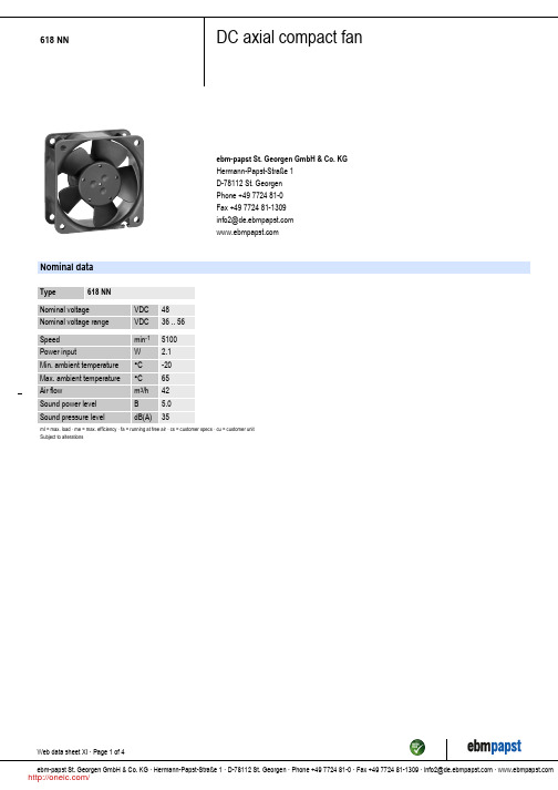
ml = max. load · me = max. efficiency · fa = running at free air · cs = customer specs · cu = customer unit Subject to alterations
Web data sheet XI · Page 1 of 4 ebm-papst St. Georgen GmbH & Co. KG · Hermann-Papst-Straße 1 · D-78112 St. Georgen · Phone +49 7724 81-0 · Fax +49 7724 81-1309 · info2@ ·
618 NN
DC axial compact fan
ebm-papst St. Georgen GmbH & Co. KG Hermann-Papst-Straße 1 D-78112 St. Georgen Phone +49 7724 81-0 Fax +49 7724 81-1309 info2@
Mass Dimensions Material of impeller Housing material Direction of air flow Direction of rotation Bearing Lifetime L10 at 40 °C Lifetime L10 at maximum temperature Connection line Motor protection Locked-rotor protection Approval
/
618 NN
DC axial compact fan
Charts: Air flow
OEM617D是Novatel推出的兼容BDS的多频测向板卡支持双路天线
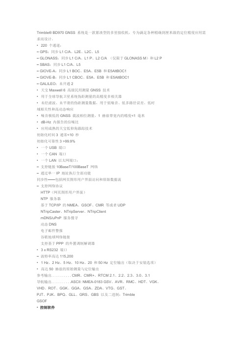
Trimble® BD970 GNSS 系统是一款紧凑型的多星接收机,专为满足各种精确到厘米级的定位精度应用需求而设计。
•220 个通道:– GPS:同步L1 C/A、L2E、L2C、L5– GLONASS:同步L1 C/A、L1 P、L2 C/A (仅限于GLONASS M)和L2 P– SBAS:同步L1 C/A、L5– GIOVE-A:同步L1 BOC、E5A、E5B 和E5AltBOC1– GIOVE-B:同步L1 CBOC、E5A、E5B 和E5AltBOC1– GALILEO:未开通2•天宝Maxwell 6 高级民用测量GNSS 技术•用于全球导航卫星系统伪距测量的高精度多相关器•未经滤波、未平滑的伪距测量数据,用于低噪音、低多路径误差、低时域相关性和高动态响应•噪音极低的GNSS 载波相位测量,1 赫兹带宽内的精度<1 毫米•dB-Hz 内报告的信噪比•应用成熟的天宝低仰角跟踪技术初始化时间3 通常<10 秒初始化可靠性3 >99.9%•一个USB 端口•一个CAN 端口•一个LAN 以太网端口:–支持链接10BaseT/100BaseT 网络–通过单一IP 地址执行全部功能同步性——包括网页图形用户界面访问和原始数据流–支持网络协议HTTP(网页图形用户界面)NTP 服务器基于TCP/IP 的NMEA、GSOF、CMR 等或者UDPNTripCaster、NTripServer、NTripClientmDNS/uPnP 服务搜寻动态DNS电子邮件警报谷歌地球网络链接支持基于PPP 的外置调制解调器• 3 x RS232 端口–波特率高达115,200• 1 Hz、2 Hz、5 Hz、10 Hz、20 和50 Hz 定位输出(取决于安装选项)•高达50 赫兹的原始测量与定位输出参考输出. . . . . . . . . . CMR、CMR+、RTCM 2.1、2.2、2.3、3.0、3.1导航输出. . . . . . . . . .ASCII: NMEA-0183 GSV、AVR、RMC、HDT、VGK、VHD、ROT、GGK、GGA、GSA、ZDA、VTG、GST、PJT、PJK、BPQ、GLL、GRS、GBS 以及二进制:TrimbleGSOF•控制软件– HTML 网页浏览器:Internet Explorer 7.0 或更高版本– Firefox 3.5 或更高版本– Safari 4.0– Opera 9– Google Chrome•每秒1 脉冲输出•事件标记输入支持LED 驱动支持. . . . . . . . . . . .(显示电源、卫星跟踪和差分数据)定位规格模式精度延迟时间最大速率同步RTK 1 cm + 1 ppm 水平2 cm + 1 ppm 垂直300 ms10 Hz低延时RTK 2 cm + 2 ppm 水平3 cm + 2 ppm 垂直<20 ms50 HzDGPS<1 m 3D<20 ms50 Hz SBAS8<5 m 3D<20 ms50 Hz物理特性尺寸. . . . . . . . . . . . . . . . . 100 mm X 60 mm X 11.6 mm电源. . . . . . . . . . . . . . . . . 3.3V DC +5%/-3%,典型1.4W (L1/L2 GPS)典型1.5W (L1/L2 GPS 和G1/G2 GLONASS)重量. . . . . . . . . . . . . . . . .62 克连接器I/O . . . . . . . . . . . . . . . . . . 24 排针转接口+6 排针转接口天线. . . . . . . . . . . . . . . . . .MMCX 插座环境特征温度工作温度. . . . . . . . . . . . . . . . –40 °C 至+75 °C储存温度. . . . . . . . . . . . . . . . .–55 °C 至+85 °C振动. . . . . . . . . . . . . . . . . . .定制:MIL810F,运行:随机6.2 gRMS限值:随机8 gRMS机械冲. . . . . . . . . . . . . . . . . MIL810D运行:±40 g限值:±75 g。
744710215;中文规格书,Datasheet资料

5.1 5.0 4.02012-06-272012-05-022009-06-30SStSStRStSStCZWürth Elektronik eiSos GmbH & Co. KGEMC & Inductive SolutionsMax-Eyth-Str. 174638 WaldenburgGermanyTel. +49 (0) 79 42 945 - 0A Dimensions: [mm]F Typical Impedance Characteristics:H4: Classification Wave Soldering Profile:H5: Classification Wave ProfileProfile FeaturePreheat- Temperature Min (T smin )- Temperature Typical (T stypical ) - Temperature Max (T smax ) - Time (t s ) from (T smin to T smax )Δ preheat to max Temperature Peak temperature (T p )Time of actual peak temperature (t p )Ramp-down rate - Min - Typical - MaxTime 25°C to 25°C Pb-Free Assembly 100°C 120°C 130°C 70 seconds 150°C max.250°C - 260°C max. 10 secondsmax. 5 second each wave ~ 2 K/s ~ 3.5 K/s ~ 5 K/s 4 minutesSn-Pb Assembly 100°C 120°C 130°C 70 seconds 150°C max.235°C - 260°C max. 10 secondsmax. 5 second each wave ~ 2 K/s ~ 3.5 K/s ~ 5 K/s 4 minutesrefer to EN 61760-1:2006H Soldering Specifications:I Cautions and Warnings:The following conditions apply to all goods within the product series of WE-SDof Würth Elektronik eiSos GmbH & Co. KG:General:All recommendations according to the general technical specifications of the data-sheet have to be complied with.The disposal and operation of the product within ambient conditions which probably alloy or harm the wire isolation has to be avoided.If the product is potted in customer applications, the potting material might shrink during and after hardening. Accordingly to this the product is exposed to the pressure of the potting material with the effect that the core, wire and termination is possibly damaged by this pressure and so the electrical as well as the mechanical characteristics are endanger to be affected. After the potting material is cured, the core, wire and termination of the product have to be checked if any reduced electrical or mechanical functions or destructions have occurred.The responsibility for the applicability of customer specific products and use in a particular customer design is always within the authority of the customer. All technical specifications for standard products do also apply for customer specific products.Washing varnish agent that is used during the production to clean the application might damage or change the characteristics of the wire in-sulation, the marking or the plating. The washing varnish agent could have a negative effect on the long turn function of the product.Direct mechanical impact to the product shall be prevented as the ferrite material of the core could flake or in the worst case it could break. Product specific:Follow all instructions mentioned in the datasheet, especially:•The solder profile has to be complied with according to the technical wave soldering specification, otherwise no warranty will be sustai-ned.•All products are supposed to be used before the end of the period of 12 months based on the product date-code, if not a 100% solderabi-lity can´t be warranted.•Violation of the technical product specifications such as exceeding the nominal rated current will result in the loss of warranty.1. General Customer ResponsibilitySome goods within the product range of Würth Elektronik eiSos GmbH & Co. KG contain statements regarding general suitability for certain application areas. These statements about suitability are based on our knowledge and experience of typical requirements concerning the are-as, serve as general guidance and cannot be estimated as binding statements about the suitability for a customer application. The responsibi-lity for the applicability and use in a particular customer design is always solely within the authority of the customer. Due to this fact it is up to the customer to evaluate, where appropriate to investigate and decide whether the device with the specific product characteristics described in the product specification is valid and suitable for the respective customer application or not.2. Customer Responsibility related to Specific, in particular Safety-Relevant ApplicationsIt has to be clearly pointed out that the possibility of a malfunction of electronic components or failure before the end of the usual lifetime can-not be completely eliminated in the current state of the art, even if the products are operated within the range of the specifications.In certain customer applications requiring a very high level of safety and especially in customer applications in which the malfunction or failure of an electronic component could endanger human life or health it must be ensured by most advanced technological aid of suitable design of the customer application that no injury or damage is caused to third parties in the event of malfunction or failure of an electronic component.3. Best Care and AttentionAny product-specific notes, warnings and cautions must be strictly observed.4. Customer Support for Product SpecificationsSome products within the product range may contain substances which are subject to restrictions in certain jurisdictions in order to serve spe-cific technical requirements. Necessary information is available on request. In this case the field sales engineer or the internal sales person in charge should be contacted who will be happy to support in this matter.5. Product R&DDue to constant product improvement product specifications may change from time to time. As a standard reporting procedure of the Product Change Notification (PCN) according to the JEDEC-Standard inform about minor and major changes. In case of further queries regarding the PCN, the field sales engineer or the internal sales person in charge should be contacted. The basic responsibility of the customer as per Secti-on 1 and 2 remains unaffected.6. Product Life CycleDue to technical progress and economical evaluation we also reserve the right to discontinue production and delivery of products. As a stan-dard reporting procedure of the Product Termination Notification (PTN) according to the JEDEC-Standard we will inform at an early stage about inevitable product discontinuance. According to this we cannot guarantee that all products within our product range will always be available. Therefore it needs to be verified with the field sales engineer or the internal sales person in charge about the current product availability ex-pectancy before or when the product for application design-in disposal is considered.The approach named above does not apply in the case of individual agreements deviating from the foregoing for customer-specific products.7. Property RightsAll the rights for contractual products produced by Würth Elektronik eiSos GmbH & Co. KG on the basis of ideas, development contracts as well as models or templates that are subject to copyright, patent or commercial protection supplied to the customer will remain with Würth Elektronik eiSos GmbH & Co. KG.8. General Terms and ConditionsUnless otherwise agreed in individual contracts, all orders are subject to the current version of the “General Terms and Conditions of Würth Elektronik eiSos Group”, last version available at .J Important Notes:The following conditions apply to all goods within the product range of Würth Elektronik eiSos GmbH & Co. KG:分销商库存信息: WURTH-ELECTRONICS 744710215。
API617-2-2002-压缩机CN

AP1 617 标准 第 7 版,2002 年 7 月 第二篇 离心与轴流压缩机
二○○三年七月译
2-Iห้องสมุดไป่ตู้
第2篇 离心与轴流压缩机
2-II
目次
第 1 章 总则 .................................……........................................................................................... 2-1 1.1 适用范围 ........................…..…................................................................................................ 2-1 1.2 术语定义 ........................….............................…..................................................................... 2-1 第 2 章 基本设计 ........................…...………………….................................................................... 2-1 2.1 通则 ........................………........................... ...........…........................................................... 2-1
德标 GN 617
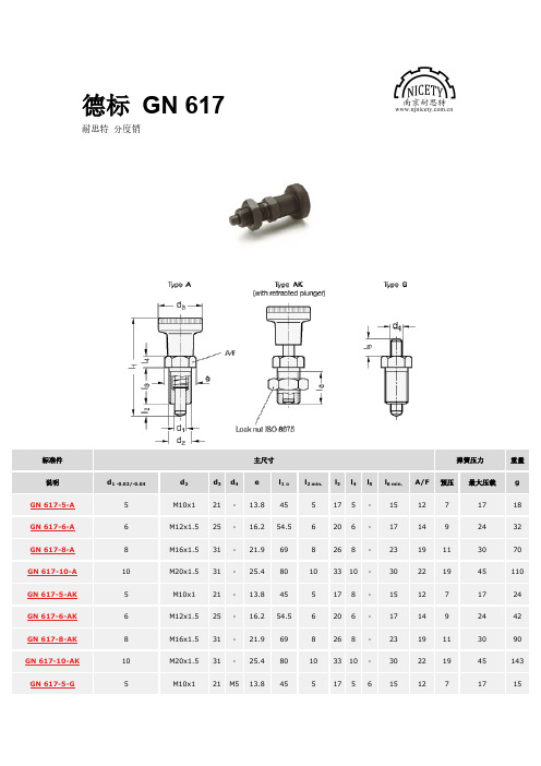
德标GN617耐思特分度销标准件主尺寸弹簧压力重量说明d1-0.02/-0.04d2d3d4e l1≈l2min.l3l4l5l6min.A/F预压最大压载g GN617-5-A5M10x121-13.8455175-151271718 GN617-6-A6M12x1.525-16.254.56206-171492432 GN617-8-A8M16x1.531-21.9698268-2319113070 GN617-10-A10M20x1.531-25.480103310-30221945110 GN617-5-AK5M10x121-13.8455178-151271724 GN617-6-AK6M12x1.525-16.254.56206-171492442 GN617-8-AK8M16x1.531-21.9698268-2319113090 GN617-10-AK10M20x1.531-25.480103310-30221945143 GN617-5-G5M10x121M513.84551756151271715标准件主尺寸弹簧压力重量说明d1-0.02/-0.04d2d3d4e l1≈l2min.l3l4l5l6min.A/F预压最大压载g GN617-6-G6M12x1.525M616.254.5620610171492425 GN617-8-G8M16x1.531M821.9698268122319113053 GN617-10-G10M20x1.531M825.480103310123022194598 GN617-5-GK5M10x121M513.84551756151271722 GN617-6-GK6M12x1.525M616.254.5620610171492435 GN617-8-GK8M16x1.531M821.9698268122319113072 GN617-10-GK10M20x1.531M825.4801033101230221945129 Technical information带螺纹的本体钢质,黑色氧化处理。
离心压缩机

DOCUMENT CERTIFICATIONDOCUMENT NO.1000218602REV.NO.0DOCUMENT NAME:As Built API617DatasheetsD-R CT:114145DATE:7/23/12NUMBER OF SHEETS:8(DOES NOT INCLUDE THIS COVER SHEET)-----NOTICE-----THIS DOCUMENT CONTAINS CONFIDENTIAL AND TRADE SECRET INFORMATION.IT IS THE PROPERTY OF DRESSER-RAND COMPANYAND IS PROVIDED TO THE RECEIVER IN CONFIDENCE.D-R Project114145Chemtex International Inc.PO CT0009.0001Mixed Refrigerant CompressorYulin Yuanheng Energy Co.Ltd.LNG ProjectD16R8B(I)-INFORMATIONTHIS DOCUMENT IS SUBMITTED FOR INFORMATION,COMMENTS ARE NOT SOLICITED NOR IS RETURNREQUIRED.(P)-PRELIMINARY/PROPOSALPRELIMINARY PRINT MUST BE RETURNED AND RECEIVED BY DRESSER-RAND NO LATER THAN______________________IN ORDER TO MAINTAIN ENGINEERING AND MANUFACTURING SCHEDULES.(R)-REVIEWCERTIFIED CORRECT FOR CONFORMITY TO THE SPECIFICATIONS.PRINT MUST BE RETURNED AND RECEIVEDBY DRESSER-RAND NO LATER THAN10WORKING DAYS AFTER ABOVE DATE IN ORDER TO MAINTAINENGINEERING AND MANUFACTURING SCHEDULES.IF REVIEW ISSUE DRAWINGS ARE NOT RETURNED ON TIME,DRESSER-RAND WILL PROCEED WITH FINAL ISSUE.X(F)-FINALCERTIFIED CORRECT FOR CONFORMITY TO THE SPECIFICATIONS.PRINT MUST BE RETURNED AND RECEIVEDBY DRESSER-RAND NO LATER10WORKING DAYS AFTER ABOVE DATE.THE DRAWING HAS BEEN PREPAREDFROM CONTRACT SPECIFICATIONS AND NECESSARY MATERIAL REQUIRED HAS ALREADY BEEN PLACED ONORDER.CHANGES IN DIMENSIONS OR ALTERATIONS IN THE MATERIAL FURNISHED WILL NOT BE ACCEPTEDUNLESS SUCH CHANGES OR ALTERATIONS ARE IN ACCORDANCE WITH CONTRACTUAL AGREEMENT ORACCOMPANIED BY WRITTEN AUTHORIZATION FROM THE PURCHASER AGREEING TO REVISIONS IN PRICE ANDDELIVERY.(Z)-AS BUILTISSUED FOR RECORD,INCORPORATING AS BUILT FEATURES.RETURN OF DOCUMENT IS NOT REQUIRED. DCCS-Document Certification Cover Sheet,REV.02,25JAN05Reference004-034-0741APPLICABLE TO:PROPOSALPURCHASEAS BUILT23456789101112131415161718192021222324252627282930313233343536373839404142434445464748495051%52TO TO %TOTO535455565758REMARKS:5960111,729BY MANUFACTURER Normal -(0423)SEC #1Rated -(0423)Rated -(0423)MODEL BY PURCHASERINFORMATION TO BE COMPLETED:MUTUAL AGREEMENT (PRIOR TO PURCHASE)(ALL DATA ON PER UNIT BASIS)D16R8B D16R8B OPERATING CONDITIONSREVISION NO.81114145-01D16R8B (DKJ Quoted)UNIT SERIAL NO.BYMANUFACTURERFOR SITE YUANHENG,CHINADRESSER-RAND SERVICE Yuanheng Natural Gas Co,Ltd.MIXED REFRIGERANT COMPRESSIOND16R8B JOB NO.1141451000218602PAGE1OFMonday,July 23,2012ITEM NO.DATE Lucas WesleyCM-301,CG-301INDUCTION MOTOR DRIVER TYPE (1-3.1.1)NO.REQUIRED DRIVER ITEM NO.D16R8B 121,085175,700RECYCLE WEIGHT FLOW,(Kg/Hr)(WET)Rated -2(0423)SEC #1SEC #2D16R8B (DKJ Quoted)1st section (0423)SEC #2Normal -(0423)POLYTROPIC HEAD (M Kgf/Kg)DISCHARGE FLANGE WEIGHT FLOW,Kg/Hr (WET)DISCHARGE FLANGE VOLUME,(M3/Min)(WET)METHODPROCESS CONTROL (1-3.4.2.1)BHP REQ.AT DRIVER INCL.EXT.LOSSES (GEAR,ETC.)(KW)SPEED (RPM)GHP REQUIRED (KW)TRAIN BHP REQUIRED EXCL.EXT.LOSSES (KW)TURNDOWN (%)SIGNALSUCTION THROTTLING CERTIFIED POINTVARIABLE INLET GUIDE VANES (2-2.4.1)FROM 2.758BarA 2.62FROM SPEED VARIATION COOLED BYPASS FROM DISCHARGE BLOWOFF DISCHARGE Power is guaranteed on an overall basis for the train.Intermediate pressure is not a guarantee.NOTE 1:IF GAS ANALYSIS IS GIVEN,MANUFACTURER SHALL SUPPLY DATA,OTHERWISE DATA SHALL BE SUPPLIED BY USERDISCHARGE FLANGE MASS FLOW RATE SHOWN ON DATA SHEETS MUST BE USED FOR SIZING PROCESS EQUIPMENT.SUCTIONBarARANGE 4-20BarGANTI-SURGE SYSTEM (1-3.4.2.2)Automatic system (antisurge controls only)-By Dresser-RandMASOURCE (1-3.4.2.1)TYPEELECTRONICPNEUMATICOTHER5,0327,586215.1143,620189,486794.7155.257.041.161 1.186184,485148,621150.0794.70.97610.920240.0010,449YESNO POLYTROPIC EFFICIENCY (%)12,72112,88184.2784.47NO80.09EXPECTED OPERATION AT EACH CONDITION (%)PERFORMANCE CURVE NUMBER 5,05079.91YES10,2776,8836,8837,6146,8837,3266,8834,904175,700FLANGE FLOWSINLET FLANGE WEIGHT FLOW,Kg/Hr (WET) 1.1610.9770107.91.16113.01 1.186THROTTLED INLET PRESSURE (BarA)INLET FLANGE VOLUME,(M3/Min)(WET)COMPRESSIBILITY (Z1)INLET VOLUME,(M3/Min)(WET)DISCHARGE CONDITIONS PRESSURE (BarA)TEMPERATURE (°C)TEMPERATURE (°C)Cp/Cv(Kavg)COMPRESSIBILITY (ZAvg)GAS HANDLED (ALSO SEE PAGE )GAS PROPERTIES (1-2.1.1.4)SM3/Hr 1.0133&15.5(DRY)WEIGHT FLOW,(Kg/Hr)(WET)INLET CONDITIONSSPECIFIED INLET PRESSURE (BarA)RELATIVE HUMIDITY (%)MOLECULAR WEIGHT Cp/Cv (Kavg)0.9337146.20.979234.3730.45180,690142,4507,299137,46054.624,886209.7151.5785.1CENTRIFUGAL AND AXIAL COMPRESSOR DATA SHEET (API 617-7TH Chapter 2)SI UNITS (1-1.6.5)1st section (0423)111.6785.134.37108.620.862.770127,13912.46143,620184,4852.770Normal -2(0423)106,693137,46033.0040.000.979912.77112.51.1850.92080.93472.60012.22 2.69420.8633.001.16130.521.185CENTRIFUGAL AND AXIAL DATA SHEET(API617-7THSI UNITS(1-1.6.5)CENTRIFUGAL AND AXIAL DATA SHEET(API617-7THSI UNITS(1-1.6.5)123RPM TRIP RPM4YES567RPM MAX MIN8RPM MAX MIN9RPM10RPM11NO.12131415RPM16RPM17RPM MAX MIN18RPM192021MICS22232425CW26272829303115,33732333435363738MATL3940MATL414243°C°C444546474849TYPE MATERIAL5051TYPE MATERIALFIXATION METHODNAMEPLATE(2-2.11.2)NORMAL CLEARANCE(mm)Shrink FitASTM B26,ASTM B108Alloy850ToothDamperASTM B26,ASTM B108Alloy850 ROTATION,VIEWED FROM DRIVEN ENDLATERAL CRITICAL SPEEDS(DAMPED)TORSIONAL CRITICAL SPEEDS:SEQUENTIAL LOW SPEED BAL.PREC.AT SPEED BAL.(1-2.6.8.6)ACCESSIBLE(2-2.8.3)ROTORINTERSTAGEDIVISION WALLDISASSEMBLY AND REASSEMBLY(1-2.6.8.2.1.1)AT SPEED BALANCING(1-2.6.8.3)LABYRINTHS:RESIDUAL BALANCE CHECK(1-2.6.8.7)GUIDE VANESPRESS.CONN.BAL LINE DOWNSTREAM(2-2.5.4.3)SHAFT SLEEVES:AT INTERSTG.CLOSERADIALASTM A350GRADE LF2,CLASS1MATERIALD16R8B193.34,489MATERIALSHAFT END:TAPEREDSHAFT:SMALLEST TIP INTERNAL WIDTH(mm)MATERIAL(8)@Grade4330BUILT UP15.801MIN.YIELD STRENGTH(kPa)(4)@685.8,(4)@590.88(3)@17,(5)@19FABRICATEDENCLOSED241INTERMEDIATE MAIN PROCESS CONNECTIONS(2-2.4.5)IMPELLERS:DIA(mm)MAX.IMPELLER HEAD@100%SPD(M Kgf/Kg)302HARDNESS:(Rc)(BRINNEL)0.75MAX.MACH.NO.@IMPELLER EYE3487 SECOND CRITICAL 10820 - 14170THIRD CRITICALFOURTH CRITICALAT CONCURRANT PRESSURE(BarA)NO.VANES EA.IMPELLERTYPE(OPEN,ENCLOSED,ETC.)TRAIN LATERAL ANALYSIS REQUIRED(1-2.6.2.6)VIBRATION:LIST OF TRAIN UNDESIRABLE SPEEDS(1-2.6.1.4)ALLOWABLE TEST LEVELQ.C.OF INACCESSIBLE WELDS(1-2.3.1.11.2)1,395BarGMAX CASING CAPACITY(M3/Min)FIRST CRITICAL 2100RADIOGRAPHY REQUIRED FORULTRASONIC REQUIRED FORNO.VANES GUIDE VANEIGV EXTERNAL PURGE(2-2.4.2)VANE CONTROL SYSTEM(2-2.4.3)MATERIALSYSTEM RELIEF VALVE SET PT.(2-2.3.1.1)MODECASING:CCWSPLINEDMATERIALS INSPECTION REQUIREMENTS(1-4.2.2.1)LOW TEMPERATURE(1-2.2.1.15.3)SEE D-R ITPSEE D-R ITPASTM A668Grade4340,Class L240.0DIA@COUPLING(mm)127.0MODELATERAL ANALYSIS ADDITIONAL REQUIREMENTS(1-2.6.2.14)(PEAK TO PEAK)THIRD CRITICALSTEADY STATE TORSIONAL ANALYSIS REQUIRED(1-2.6.7.1)AREA277BHN/321HBCYLINDRICALINTEGRAL FLANGE65860.215723,94949.99MAX.ALLOWABLE PRESS-28.9MIN.DESIGN METAL TEMPERATURE(°C)OTHER TRAIN COMPONENTS(1-2.2.1.15.2)MODELCASING SPLITBarG88.9193.3-28.9HYDROMAX OPER.TEMP.MIN.OPER.TEMP.TEST PRESS(BarG):MAX.ALLOWABLE TEMPERATURE(°C)75.003.175THICKNESS(mm)CORR.ALLOW.(mm)US CUSTOMARY METRICLIQUID PENETRANT REQUIRED FORMAGNETIC PARTICLE REQUIRED FORSEE D-R ITPSEE D-R ITP25.4SECOND CRITICALCENTRIFUGAL AND AXIAL COMPRESSORDATA SHEET(API617-7TH Chapter2)SI UNITS(1-1.6.5)FIRST CRITICALFOURTH CRITICALMODEMODEMAX.CONT.MAX.TIP SPEEDS:FPS@100%SPEEDCONSTRUCTION FEATURES6911811SPEEDS:NO(2-2.4.8)JOB NO.114145-01ITEM NO.100021860223-Jul-12REVISION NO.0DATEBY8DISCH.PRESSURE(BarA)INLET PRESSURE(BarA)Lucas Wesley814PAGE 4OF6911FPS@MAX.CONT.SPEEDDIAPHRAGMS:MATERIALAXIALLY SPLITAT SHAFT SEALSASTM A36Carbon Steel PlateASTM A743Grade CA-15mm²ASTM A743Grade CA-15FLOW WITH NORMAL CLEARANCE(Kg/Hr)FLOW WITH2x NORMAL CLEARANCE(Kg/Hr)CLEARANCE POINTSMAX TORQUE CAPABILITY(N-M)MATERIAL8620528TYPE FABRICATIONSHAFT HARDNESS(BNH)(Rc)DIVISION WALL:DIA@IMPELLERS(mm)ONE PIECEMIN.YIELD STRENGTH(kPa)12SHAFT SEALS:345678910111213TYPE(SEPARATE,INTEGRAL)14MATERIAL15161718192021222324252627282930311011121314151617183233343536373839STATOR40414243444546474849METHOD OF CONTROL(1-2.8.1.5)ADJUSTABLE)(2-3.4.2.3)AXIALMAX.lit/Min@SPLITBEARING HOUSING CONSTRUCTION:(MOVABLE,FIXED,REMARKS:BarAAIR RUN-IN OTHERFLOW(PER SEAL):NORM:BUFFER GAS CONTROL SYSTEM SCHEMATIC BY VENDORPRESSURIZING GAS FOR SUBATMOSPHERIC SEALS(1-2.8.2.4)EDUCTOR INJECTION(1-2.8.2.3)SEAL MANUFACTURERROTORSTATORROTORTYPELEAKAGE TO PROCESS(GAL/DAY/SEAL)BUFFER GAS REQUIRED FOR:Kg/HrBLADE QUANTITY(MOVABLE,FIXED,TYPECORD WIDTH(mm)BLADE MATERIALBLADE QUANTITYBLADE HEIGHT(mm)OUTER DIAMETER(mm)CORD WIDTH(mm)BLADE ROOT TYPEBLADE MATERIALBLADE QUANTITYCORD WIDTH(mm)BLADE MATERIALBLADE QUANTITYBLADE HEIGHT(mm)OUTER DIAMETER(mm)CORD WIDTH(mm)BLADE MATERIALBLADE ROOT TYPE456789 CENTRIFUGAL AND AXIAL COMPRESSOR0DATA SHEET(API617-7TH Chapter2)REVISION NO.8PAGE 5OFFLOWRATEFILTRATIONMANIFOLD(1-2.8.1.7)SI UNITS(1-1.6.5)PRESSURE(1-2.8.1.6)TYPE BUFFER GAS(1-2.8.1.5)BUFFER GAS SYSTEM REQUIRED(1-2.8.1.5)SEALS(1-2.8.3.4)TYPECONSTRUCTION FEATURES(CONTINUED)AXIAL COMPRESSORSUPPLEMENTAL DEVICE REQUIRED FOR CONTACTMIN.SEALING PRESSURE(BarA)MAX SEALING/SETTLING OUT PRESSURE(1-2.8.1.1)(BarA)SEAL TYPE(1-2.8.1.3)Gas31.03SEPARATE23-Jul-12DATEBY Lucas WesleyJOB NO.114145-01ITEM NO.1000218602ADJUSTABLE)(2-3.4.2.3)STAGESTAGE123Astm A514&Astm A36,Astm A283,Astm A366,Astm A569,Astm A675Grade60,Grade D123456789101112131415161718192021222324252627NO.128104SEC2930NO.131OTHER 321333435363738°C39127°CSEC4041813SEC4243444546474849505152535455565758ALARM MODELSCALE RGE SET @BY VENDOR (1-2.3.2.2.7)STUDDED MICSMFR.GAS VELOCITY ORIENTATION FLANGED OR 609.6(M/SEC)(1-2.3.2.2.1)MATING FLG &GASKET series A,B;ISO 7005-1,-2;ANSI/ASME OTHERFACING BORECONNECTION (B16.1;B16.5;B16.42;B16.4720600#RF Up 36600#RF BOROSCOPIC INSPECTION PORTS (2-2.3.2.4)Flanged 19.480072820600#RFUpFlanged600#RF Up 14.8187664Flanged 23.6293152Flanged 20.609052CASING CONNECTIONS (1-2.3.2.2.1)Inlet #1-1Disch #1-2Disch #2-3Inlet #2-4Up 10COMPRESSORGEAR H.S.GEAR L.S.TIME DELAYKEY PHASOR REQUIRED SET @SHTDWN:3300XL2TYPE MODELBENTLY NEVADAProximity/Non Contacting NO.REQUIRED MFRMFR.MODELMONITOR SUPPLIED BY (2-3.4.7.2)LOCATION ENCLOSURE MFRMODEL BEARING TEMPERATURE DETECTORS (2-3.4.7.3)VIBRATION DETECTORS:SEE ATTACHED API-670DATA SHEET MICSMODELTYPE MFRNO.AT EA SHAFT BEARINGProximity/Non Contacting TOTAL NO.2712.491Grade 4340(2-2.7.2.3)mmPIVOT:CTR/OFFSET,(%)PAD MATERIAL (2-2.7.2.2)BEARING SPANUNIT LOAD (ACT/ALLOW)(PSI)COPPER BACKED (2-2.7.3.7)FLOODED INTEGRAL LUBRICATION:THRUST COLLAR:MATERIALDIRECTED (2-2.7.3.6)REPLACEABLE5Steel 1.65PIVOT:CENTER /OFFSET,(%)PAD BASE MATL NO.PADS0.55Damper-TiltpadRMT I 111.252152.4484.667/2240.796Steel 1.6BTWN PIVOT0.55Damper-TiltpadRMT I 111.252THRUST 152.4BTWN PIVOT454.427/2240.7960DATE Lucas WesleySI UNITS (1-1.6.5)REVISION NO.DATA SHEET (API 617-7TH Chapter 2)6OF8PAGEBEARINGS AND BEARING HOUSINGS BYNON-THRUST THRUSTJOB NO.114145-01ITEM NO.1000218602LENGTH (mm)NO.PADSBASE MATERIALSHAFT DIA.(mm)BABBIT THICKNESS (mm)CENTRIFUGAL AND AXIAL COMPRESSOR MAGNETIC BEARINGS (2-2.7.1.1.2)RADIALCONSTRUCTION FEATURES (CONTINUED)223-Jul-12OHMSPlatinum100SEE ATTACHED API-670DATASHEET TYPELOAD:B'TWN/ON PAD MANUFACTURER EA PADEVERY OTH PAD2EA PADOTHERLOCATION-THRUST BRG NO.(INACT)OTHERMONITOR SUPPLIED BY (2-3.4.7.4)PER BRGPER BRG2EVERY OTH PADMFR.MODELLOCATION ENCLOSURE118SHTDWNSET @TIME DELAYSCALE RGE ALARM SET @THERMOCOUPLES TYPE RESISTANCE TEMP DETECTORSRESISTANCE MAT'L3300XL BENTLY NEVADA24OSCILLATOR-DETECTORS SUPPLIED BYALARM TEMPERATURE (°C)(2-2.7.1.3)SHUTDOWN TEMPERATURE (°C)(2-2.7.1.3)PER BRG127PROVISION FOR LOCAL DISCONNECT (1-2.7.4.6)LOCATION-JOURNAL BRG 118EA PADEVERY OTH PADMFRMODELLOCATION ENCLOSUREMONITOR SUPPLIED BY (2-3.4.7.2)SEE ATTACH.API-670DATA SHEET OSCILLATOR-DEMODULATOR SUPPLIED BYTIME DELAYMICSSET @MICS82.55AREA (mm²)AXIAL POSITION DETECTOR:SET @CASING VIBRATION TRANSDUCERS (2-3.4.7.5)CASING VIBRATION MONITORS (2-3.4.7.6)SCALE RGE ALARM SHTDWN:6Offset ,0.6Offset ,0.6INACTIVEACTIVESelf Equalizing -Tilting PadMANUFACTURER63447.3796894.757UNIT LOAD (ULT.)(kPa)UNIT LOADING (MAX)(kPa)SteelKingsbury 20258.024TYPESteelSelf Equalizing -Tilting PadKingsbury 3447.3796894.75720258.024123PRESSURE 4TEMPERATURE 5SOLVENT INJECTION 6PURGE FOR:7BRG.HOUSING 8BTWN BRG &SEAL 9BTWN SEAL &GAS101112131415161718ISO 3219202122232425262728mm 29kgS 30mm 31kgS32333435mm363738mm 394041424344REMARKS:4546474849SPACER LENGTH QUANTITY PER HUBDiskTYPE:FULLY ENCLOSEDSEMI-OPENOTHERSPACER WEIGHTCOUPLING DETAILSMAX O.D.HUB WEIGHT COUPLING FURNISHED BY DRESSER-RANDMODELCOUPLING GUARD FURNISHED BY:MANUFACTURER Kop-FlexTYPENOTE:SEE ROTATING ELEMENTS -SHAFT ENDS SEE ATTACHED API-671DATA SHEETKEYLESS HYDRAULICKEYEDFLANGEDOTHEROIL TYPE (2-2.10.2)COMBINED (2-2.10.1)ACCESSORIESCOUPLING AND GUARDS (3.2)SEPARATE INTEGRAL OIL RESERVOIR (1-3.3.2.11)SEE ATTACHED API 614DATASHEET INDIVIDUAL STAGE DRAINS REQUIRED (1-2.3.2.1.7)VALVED &BLINDEDVALVED &BLINDED &MANIFOLDLUBRICATION AND SEALING SYSTEMS (1-2.10)(1-3.5.1.2)TYPENO.SIZE BYSI UNITS (1-1.6.5)OTHER CONNECTIONSSERVICE:LUBE-OIL INLET NO.SIZETYPEREVISION NO.023-Jul-12DATA SHEET (API 617-7TH Chapter 2)7OF8Lucas WesleyDATE PAGE114145-011000218602CENTRIFUGAL AND AXIAL COMPRESSOR JOB NO.ITEM NO.LUBE OIL OUTLET SEAL-OIL INLET SEAL-OIL OUTLET PLUG AND RING GAUGES (1-3.2.5)SEAL GAS INLET SEAL GAS OUTLET CASING DRAINS STAGE DRAINSOTHERNONSKID DECKING (1-3.3.2.4)LEVELING PADS OR TARGETS (1-3.3.2.6)COLUMN MOUNTING (1-3.3.2.5)OTHERMOUNTING PLATES (1-3.3)BASEPLATES FURNISHED BY (1-3.3.2.1)COMPRESSOR ONLY GEARCONT.OIL LUBESUB-SOLE PLATES REQUIRED (1-3.3.2.10)STAINLESS STEEL SHIM THICKNESSMACHINED MOUNTING PADS REQUIRED (1-3.3.2.9)DRIVERSLOPED DECK (1-3.3.2.4.1)mm6.35lit/MinEXTENT OF PIPING (2-3.5.1.1)COMPRESSORLUBRICATION REQUIREMENTS:NON-LUBE COUNTER BORE ANCHOR BOLT HOLES (1-3.3.3.1.2)STAINLESS STEEL SHIM THICKNESSSOLEPLATES FURNISHED BY (1-3.3.3.1)THICKNESSSUBSOLE PLATES REQUIRED (1-3.3.3.1.3)12MANUALS34°C5°C MISCELLANEOUS:6°C7°C8°C9°C1011121314151617181920212223242526272829303132L W H 3334353637P38394041424344454647484923-Jul-12JOB NO.REVISION NO.PAGE1000218602 CENTRIFUGAL AND AXIAL COMPRESSOR0ITEM NO.114145-01DATELucas WesleyDRAFT MANUAL FOR REVIEW(1-5.3.5.1.2)SI UNITS(1-1.6.5)8OFDATA SHEET(API617-7TH Chapter2)DRIVERSUTILITY CONDITIONS:STEAM:INLET MINUTILITIESBYDRIVER GEARTECHNICAL DATA MANUAL(1-5.3.5.4)8DRIVER BASE MAXNORMELECTRICITY:EXHAUST.MINMAXNORMBarGBarGBarGBarGBarGBarG11SHUTDOWN100002424DRIVERS CONTROLMIN PRESSPHASEVOLTAGEHERTZREDUCED VOLTAGE START(1-3.1.6)50DC DC3BarGSHOP INSPECTION AND TESTS:(1-4.1.4)REQ'D WIT/OBVNUMBER OF STARTS(1-2.6.7.6.4)INSTRUMENT AIR:MAX PRESS BarGINTERMEDIATE HEAD/PRESSURE TOL.(2-4.3.3.1.6)HYDROSTATIC(1-4.3.2)IMPELLER OVERSPEED(1-4.3.3)MECHANICAL RUN(1-4.3.6)(2-4.3.1)PURCHASER VIB.EQUIPMENT(2-4.3.1.1.10)VARY LUBE&SEAL OIL PRESSURESAND TEMPERATURES(1-4.3.6.1.5)PERFORMANCE TEST(GAS)(AIR)(2-4.3.3.1.1)BEFORE GAS LEAKAGE TESTAFTER GAS LEAKAGE TESTCONTRACT COUPLINGOPTIONAL TESTSTOTAL SHIPPING WEIGHT162420366(Compressor Bundle)MAX.FOR MAINTENANCE(IDENTIFY)WEIGHTS(kg):COMPR.39463POST TEST INTERNAL INSP.(1-4.3.8.5)TAPE RECORD VIB DATA(1-4.3.6.1.3)SHAFT END SEAL INSP.(1-4.3.6.2.2)GAS LEAK TEST AT DISCH PRESS(2-4.3.2.3)COMPR.ROTORS:POLAR FORM VIB DATA(1-4.3.6.1.2)SOUND LEVEL TEST(1-4.3.8.3)FULL LOAD/SPEED/PRESS TEST(1-4.3.8.6)HYDRAULIC COUPLING INSP(1-4.3.8.7)INSPECTOR'S CHECKLIST COMPLIANCE(1-4.1.6)COMPLETE UNIT TEST(2-4.3.3.2)TANDEM TEST(2-4.3.3.3)GEAR TEST(2-4.3.3.4)HELIUM LEAK TEST(1-4.3.8.2)GAS SEAL TEST VENDOR SHOP(1-4.3.5)AUX.EQUIPMENT TEST(1-4.3.8.4)SPARE PARTS TEST(1-4.3.8.8)WWWWPROVISION FOR LIQUID INJECTION(1-2.1.10)INJECTION MANIFOLD(2-3.5.1.2)VENDOR'S REVIEW&COMMENTS ON PURCHASER'SRECOMMENDED STRAIGHT RUN OF PIPE DIAMETERSBEFORE SUCTION2COMPRESSOR TO BE SUITABLE FOR FIELD RUN-IN ON AIR(1-2.1.16)INSPECT CLEANLINESS(1-4.2.1.4)DESIGN AUDIT(1-5.1.4)CONTROL SYSTEMS(1-3.4.1.1)SHOP FITUP OF VENDOR PROCESS PIPING(1-4.4.3.11)WELDING HARDNESS TESTING(1-4.2.1.5)PROVIDE TAIL END SCHEDULES(1-5.3.3.2)VENDOR'S REPRESENTATIVE SHALL(1-2.1.13)OBSERVE FLANGE PARTINGCHECK ALIGNMENT AT TEMPERATUREBE PRESENT AT INITIAL ALIGNMENTGEARREMARKS:COMPRESSOR UPPER CASE39463SPACE REQUIREMENTS(m&mm):COMPLETE UNIT:。
电子元器件ZUMT617中文资料_数据手册_IC数据表
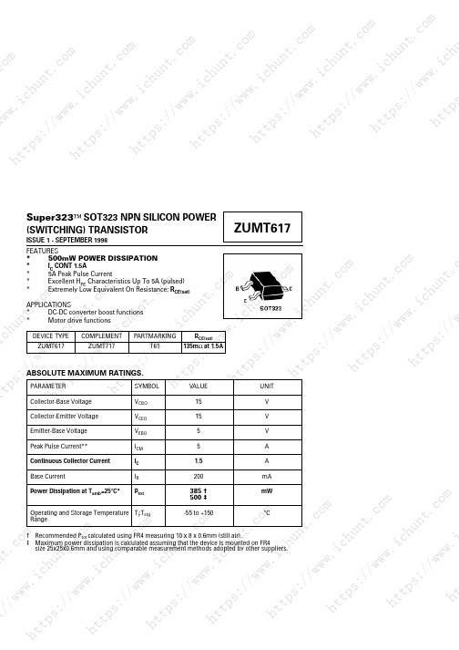
Super323™ SOT323 NPN SILICON POWER (SWITCHING) TRANSISTORISSUE 1 - SEPTEMBER 1998FEATURES*500mW POWER DISSIPATION*I C CONT 1.5A*5A Peak Pulse Current*Excellent H FE Characteristics Up To 5A (pulsed)*Extremely Low Equivalent On Resistance; R CE(sat)APPLICATIONS *DC-DC converter boost functions *Motor drive functions†Recommended P tot calculated using FR4 measuring 10 x 8 x 0.6mm (still air).‡Maximum power dissipation is calculated assuming that the device is mounted on FR4size 25x25x0.6mm and using comparable measurement methods adopted by other suppliers.ps :t.co mh t t psn t.co ms :/ch un t.co mh tt p s ://w w w .t ps ://w ww n t.co m.ic hu nt .c o://h un t.co mh tt p s://ww w.itt ps ://w ww .i ch un t .c o m w .i ch un t.ct tp s://wu nt .c omh tt ps ://w ww .i ch tt ps ://w w w .i c h u n t .cww .i ch un t.i ch un t.co mh tt ps ://w ww .i ch h t t p s ://ww ww .i ch un th tt ps ://w ww .i ch u/w ww .i ch un o mh tt ps ://w ww .i ch un //w ww .i ch un t.co mh tt ps ://w ww .i ch un t://w ww .i c h u n t.c o mw ww .i ch un t.s ://w w w .i ch t t p sn t.ch tt p s ://w w w .un t.co m.ic h tt p s://ww w.is ://w ww .i ch un t .c o m w .i t tp sh tt ps ://w ww .i ch tt ps ://w w w .i c h u n t .cww .i ch uh tt ps ://w ww .i ch h t t p s ://ww ww h tt ps ://w ww .i ch u/w wco mh tt ps ://w ww .i ch un //w ww .i ch un t.co mh tt ps ://w ww .i ch un t://w ww .i c h u n t.c o mw ww .i ch un t.s ://w w w .ic1m1m1m100m1001m1mI C - Collector Current (A)V CE(sat)v I C0V C E (s a t )- (V )IC/IB=10IC/IB=50IC/IB=100+25°C -55°Ch F E - T y p i c a l G a i n+100°C 0I C - Collector Current (A)h FE v I CV B E (o n )- (V )+100°C +150°CV C E (s a t )- (V )+25°C 0I C - Collector Current (A)V CE(sat) v I C+100°C +150°CV B E (s a t )- (V )+25°C 0I C - Collector Current (A)V BE(sat)v I C1s 100ms I C - C o l l e c t o r C u r r e n t (A )10DC 10m10ms 1ms 100us+25°C-55°C IC/IB=50VCE=2V -55°C IC/IB=50+25°C +150°C+100°C -55°C 10m100m1100.10.20.30.40.10.20.30.410m100m11020040060080010m 100m 11010m100m1101.00.250.50.7510m 100m 1100.60.20.40.81.0110100m1TYPICAL CHARACTERISTICSh t t p s ://w ww .i c h un t .c o mh tt p sn t .co mh tt p s ://w w w .i ch u n t.c o m h tt p s://w w w .h t t ps ://w w w .i c h u n t.c o m.ic hu nt .c omh t t p s ://w w w .i c h u n t .c o mh tt p s ://ww w.ih t t p s ://w ww .i c h un t.co mw .i ch un t.co mt t p s ://w w w.ic h u n t .c o mh tt ps ://w w w .i ch tt ps ://w ww .i c h un t.cww .i ch un t.co mi ch u n t .c o m h t t ps ://w w w .i c h h t t p s ://ww ww .i ch un t.co mh t t p s ://w ww .i ch u/w ww .i ch un t.co mh tt ps ://w ww .i c h un //w ww .i ch un t.co mh t t p s ://w w w .i c h u n t://w ww .i ch un t.co mw w w .i c h u n t .s ://w ww .ic。
SC617中文资料
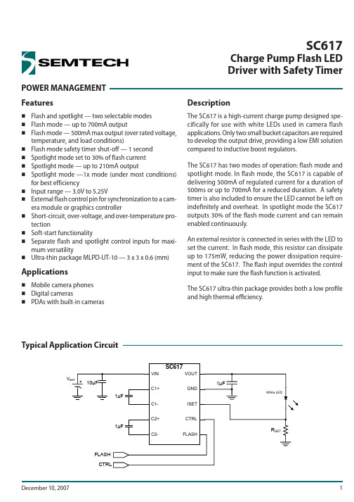
POWER MANAGEMENT SC617Charge Pump Flash LED Driver with Safety TimerFeaturesFlash and spotlight — two selectable modesFlash mode — up to 700mA outputFlash mode — 500mA max output (over rated voltage, temperature, and load conditions)Flash mode safety timer shut-off — 1 second Spotlight mode set to 30% of fl ash current Spotlight mode — up to 210mA outputSpotlight mode —1x mode (under most conditions) for best efficiencyInput range — 3.0V to 5.25V External fl ash control pin for synchronization to a cam-era module or graphics controllerShort-circuit, over-voltage, and over-temperature pro-tectionSoft-start functionality Separate fl ash and spotlight control inputs for maxi-mum versatilityUltra-thin package MLPD-UT-10 — 3 x 3 x 0.6 (mm)ApplicationsMobile camera phones Digital camerasPDAs with built-in camerasDescriptionThe SC617 is a high-current charge pump designed spe-cifically for use with white LEDs used in camera flash applications. Only two small bucket capacitors are required to develop the output drive, providing a low EMI solution compared to inductive boost regulators.The SC617 has two modes of operation: fl ash mode and spotlight mode. In fl ash mode, the SC617 is capable of delivering 500mA of regulated current for a duration of 500ms or up to 700mA for a reduced duration. A safety timer is also included to ensure the LED cannot be left on indefi nitely and overheat. In spotlight mode the SC617 outputs 30% of the fl ash mode current and can remain enabled continuously.An external resistor is connected in series with the LED to set the current. In fl ash mode, this resistor can dissipate up to 175mW, reducing the power dissipation require-ment of the SC617. The fl ash input overrides the control input to make sure the fl ash function is activated.The SC617 ultra-thin package provides both a low profi le and high thermal effi ciency.V Typical Application CircuitPin Confi gurationMarking InformationOrdering InformationDevicePackageSC617ULTRT (1)(2)MLPD-UT-10 3×3SC617EVBEvaluation BoardNotes:(1) Available in tape and reel only. A reel contains 3,000 devices.(2) Lead-free package only. Device is WEEE and RoHS compliant.617yyww xxxxyyww = Date codexxxx = Semtech Lot NumberExceeding the above specifi cations may result in permanent damage to the device or device malfunction. Operation outside of the parametersspecifi ed in the Electrical Characteristics section is not recommended.NOTES:(1) Tested according to JEDEC standard JESD22-A114-B.(2) Calculated from package in still air, mounted to 3 x 4.5 (in), 4 layer FR4 PCB with thermal vias under the exposed pad per JESD51 standards.Absolute Maximum RatingsVIN (V) . . . . . . . . . . . . . . . . . . . . . . . . . . . . . . . . . . . . -0.3 to +6.5VOUT (V) . . . . . . . . . . . . . . . . . . . . . . . . . . . . . . . . . . -0.3 to +6.5C1+, C2+ (V) . . . . . . . . . . . . . . . . . . . . . . . -0.3 to (V OUT + 0.3)Pin Voltage - All Other Pins (V) . . . . . . -0.3 to (V IN + 0.3)Circuit Duration . . . . . . . . . . . . . . . . . . . . . . . . . . . . Continuous ESD Protection Level (1) (kV) . . . . . . . . . . . . . . . . . . . . . . . . . . . . 2Recommended Operating ConditionsAmbient Temperature Range (°C) . . . . . . . . . . . . -40 to +85Thermal InformationThermal Resistance, Junction to Ambient (2) (°C/W) . . . . . 40Junction Temperature Range (°C) . . . . . . . . . . . . -40 to +150Storage Temperature Range (°C) . . . . . . . . . . . . . -60 to +150Peak IR Refl ow Temperature (10s to 30s) (°C) . . . . . . . +260Unless otherwise specifi ed: T A = 25°C for TYP , -40°C to +60°C for MIN and MAX; C BUCKET = C OUT = 1.0μF (ESR < 0.1Ω); C IN = 10.0μF; V IN = 3.0V to 5.25V; V OUT = 2.8V to 4.25V; R SET = 0.5Ω (0.1%).Parameter Symbol ConditionsMin TypMax UnitsOutput CurrentI OUTFLASH high, R SET = 0.357Ω3.7V < V IN < 4.2V, V OUT = 3.7V (1)700mAFLASH high, R SET = 0.5Ω3.3V < V IN < 4.2V 2.8V < V OUT < 4.25V 460500540FLASH low, CTRL high, R SET = 0.357Ω3.7V < V IN < 4.2V, V OUT = 3.4V (1)210FLASH low, CTRL high, R SET = 0.5Ω3.0V < V IN <4.5V 2.8V < V OUT < 4.5V120150180ISET Reference VoltageV ISETFLASH high, R SET = 0.5Ω3.3V < V IN < 4.2V 2.8V < V OUT < 4.25V 230250270mVFLASH low, CTRL high, R SET = 0.5Ω3.0V < V IN <4.5V 2.8V < V OUT < 4.5V607590Quiescent CurrentI QFLASH high3.4 5.0mA FLASH low, CTRL high 2.04.5mA FLASH low, CTRL low0.12.0μAElectrical CharacteristicsParameterSymbolConditionsMin Typ MaxUnitsFlash Mode Pulse Duration (2)t FLASH 3.3V < V IN < 4.2V I OUT = 500mA, V OUT > 2.8V 500ms Flash Mode Start-Up Time (2)t F-SU t = 0 when FLASH goes high to I OUT = 90% of fi nal value1ms Flash Mode Safety Timer (2)t SAFE FLASH high0.90 1.25s Spotlight Mode Start-Up Time (2,3)t S-SU V IN = 4.2V, V OUT = 3.2V; t = 0 when CTRL goes high to I OUT = 90% of fi nal value1ms Oscillator Frequency f OSC Device enabled250kHzOscillator Frequency Accuracy Δf OSC -1515%Short-Circuit Output Current Limit I SCSteady State with VOUT shorted to GND600mAInput Current LimitI LIMIT 2x mode, 3.3V < V IN < 4.2V1.02.1A2x mode, V IN = 3.7V, V OUT = 3.7V, T A = 25°C1.38 1.53Over-Temperature Protection(2)T OT Rising threshold 150°CT OT -HYSHysteresis 10Logic Input High Threshold V IH FLASH, CTRL 1.5V Logic Input Low ThresholdV IL FLASH, CTRL 0.4VLogic Input High CurrentI IH FLASH12035μACTRL 24070Logic Input Low CurrentI IL FLASH, CTRL0.12.0μA ISET Ripple Voltage V ISET(P-P)Spotlight mode — I OUT = 100mA 25mVFLASH mode — I OUT = 500mA100Electrical Characteristics (continued)Notes:1) V OUT required by the typical LED at this current.2) Guaranteed by design - not tested in production.3) If conditions force 2x mode operation, this start-up time will increase by approximately 32ms due to the timer that is enabled to ensure 2xmode is needed.Typical CharacteristicsFlash Current at 10ms, R ISET = 500mΩ, V OUT= 3.75V4854904955005055105153.33.453.63.75 3.94.054.2VIN (V)L E D C u r r e n t (m A )Flash Current at 500ms, R ISET = 500m Ω, V OUT = 3.58V4854904955005055105153.33.45 3.6 3.75 3.94.05 4.2VIN (V)L E D C u r r e n t (m A )Spotlight Current, R ISET = 750mΩ, V OUT= 2.93V80.088.096.0104.0112.0120.03.003.45 3.904.35 4.805.25VIN (V)L E D C u r r e n t (m A )Flash Duration, R ISET = 500mΩ, V OUT = 3.75V (start),3.58V (LED Heated 500ms)485491497503509515100200300400500Pulse Duration (ms)L E D C u r r e n t (m A )Flash Duration, R ISET = 350mΩ, V OUT = 3.86V(start), 3.61V (LED Heated 500ms)675695715735755100200300400500Pulse Duration (ms)L E D C u r r e n t (m A )Flash Current at 100ms, R ISET = 500mΩ, V OUT= 3.68V4854904955005055105153.33.45 3.63.75 3.94.05 4.2VIN (V)L E D C u r r e n t (m A )Typical Characteristics (continued)Flash Mode Ripple, R ISET = 500mΩTime (200ms/div)Safety Timer Shut-OffTime (40μs/div)Start-Up Flash Mode, 500mACh 1: 100mV/DIV Ch 2: 200mV/DIV Ch 3: 200mV/DIVTime (4μs/div)Ch 1: 100mV/DIV Ch 2: 2V/DIVCh 3: 2V/DIVCh1: 100mV/DIV Ch2: 2V/DIV Ch3: 5V/DIVSpotlight 1x Mode Ripple, R ISET = 500mΩTime (4μs/div)Ch1: 50mV/DIV Ch2: 50mV/DIV Ch3: 50mV/DIVShort Circuit Current Limiting, V IN = 5.25V, V OUT = 0VTime (400ms/div)Ch1: 2V/DIV Ch4: 100mA/DIVSpotlight 2x Mode Ripple, R ISET = 500mΩTime (4μs/div)Ch1: 50 mV/DIV Ch2: 100 mV/DIV Ch3: 100 mV/DIVPin DescriptionsPin# Pin Name Pin Function1 VIN Input voltage2C2-Negative terminal of bucket capacitor 23GND Ground— connect to ground plane using multiple vias4C1-Negative terminal of bucket capacitor 15FLASH Flash mode enable pin— puts the device in active fl ash mode when high and also overrides CTRL.6ISET Current-setting reference pin — connect to the LED cathode and the current setting resistor.7CTRL Control input bit — used to enable and set the output current in spotlight mode when high.8C1+Positive terminal of bucket capacitor 19VOUT Output pin — connect to the LED anode10C2+Positive terminal of bucket capacitor 2T Thermal Pad Pad for heat sinking purposes — not connected internally. Connect to ground plane using multiple vias.Block DiagramC1+C1-C2+C2-VOUTISETVIN CTRL FLASHGNDGeneral OperationThe SC617 is a powerful dual-mode charge pump designed to drive a high-intensity white LED. A constant current spotlight mode or a pulsed current with higher intensity is used for camera fl ash. The device operates in 2x mode while operating in fl ash mode. In spotlight mode it can operate in either 2x or 1x mode depending on the load current, load voltage, and input voltage levels.In fl ash mode the SC617 output can drive 500mA at 4.25V into an LED for a minimum duration of 500ms under all temperature and input conditions. The FLASH pin is used to trigger this mode (active high). In spotlight mode the SC617 regulates the output current to 30% of the fl ash mode current setting, when the CTRL pin is pulled high and the FLASH pin is low. Flash mode has priority over spotlight mode, i.e., the FLASH pin triggers fl ash mode regardless of the state of the CTRL pin.Output current is regulated by attaching the ISET pin to the cathode(s) of the LED package and a low resistance sense resistor (typically 0.5Ω). The ISET pin monitors the voltage at the cathode and signals the charge pump to increase or decrease the output current until the ISET voltage reaches the programmed setting. The resistor value is chosen to set the current through the LED based on this reference voltage. The resistor can be chosen to set either the flash mode current or spotlight mode current, but it should not be less than 0.35Ω due to output current limitations of the device.Flash ModeFlash mode is enabled whenever the FLASH pin is pulledhigh and remains active until the FLASH pin is released. This mode has higher priority than spotlight mode, so the state of the CTRL pin is overridden whenever the FLASH pin is activated. While in fl ash mode the reference voltage on the ISET pin is set to 250mV. The duration of the pulse is limited by the amount of power that can be dissipated in the SC617 before it exceeds the maximum operating temperature. If an output current less than the rated 500mA is desired, the duration of the pulse can increase proportionally.Extending fl ash mode beyond the 500ms pulse limit could adversely affect the long term reliability of the SC617. Flash duration must be derated at higher currents. Forexample, 700mA derates to a maximum of 350ms. In fl ash mode, I OUT = 250mV/R ISET . Figure 1 shows maximum flash mode current for extended duration times.010020030040050060070080001002003004005006007008009001000Flash Duration [ms]F l a s h C u r r e n t [m A ]Figure 1 — Maximum Flash DurationFlash Mode Safety TimerThe SC617 provides a time-out protection function when in fl ash mode. The output is disabled if the FLASH pin is held high for longer than 1 second to protect the LED. Once this time-out has occurred, the output will stay dis-abled until the FLASH pin has been pulled low and then re-enabled.Spotlight ModeSpotlight mode is enabled by setting the CTRL pin high and keeping the FLASH pin low. When in spotlight mode, the SC617 can maintain a constant current indefi nitely to drive an LED or bank of LEDs. The ISET reference voltage is set to 75mV so that the output current is maintained at 150mA when a 0.5Ω resistor is used. Spotlight current is always 30% of fl ash current for any given value of R ISET . In spotlight mode, I OUT = 75mV/R ISET .To maximize power efficiency, the SC617 has been designed to operate in 1x mode when conditions do not require the charge pump to be active. When fi rst enabled the SC617 attempts to regulate the voltage on the ISET pin in 1x mode. If the voltage on the ISET pin cannot be maintained and this condition persists for longer than 32ms, then the charge pump will change to 2x mode operation. In a typical application, the SC617 will operate in 1x mode until the supply voltage decreases suffi cientlyApplications InformationApplications Information (continued)that the voltage on the ISET pin can no longer be main-tained. After a 32ms delay (included to prevent false transitions) the charge pump will convert to 2x mode. After the charge pump switches from 1x mode to 2x mode, the device remains in 2x mode until the part is turned off . If the part is re-enabled in spotlight mode, it will begin operation in 1x mode and determine the appropriate mode of operation as previously described.Protection CircuitryThe SC617 provides several protection features to safe-guard the device from catastrophic failures. These features include:Input Over-Voltage Protection (IOVP)Output Over-Voltage Protection (OVP)Over-Temperature Protection (OTP)Over-Current Protection (OCP)Short-Circuit Current Protection (SCCP)Input Over-Voltage ProtectionIOVP is included to prevent operation at high input volt-ages that could damage the device. The IOVP circuit senses the input voltage and determines when the supply exceeds 6V. Hysteresis is included in this circuit to avoid chattering between states. When the voltage rises above this threshold, the device is disabled until the input voltage drops to a level within the specifi ed range.Output Over-Voltage ProtectionOutput OVP prevents the SC617 from generating an output voltage that could damage other devices con-nected to it such as load LEDs and bypass capacitors. When the output voltage exceeds 5.5V, the OVP circuit disables the charge pump until the voltage decreases to a level within the acceptable range. This circuit allows the device to drive LEDs with high forward voltages at a reduced level without exceeding the output voltage limits specifi ed for the device. Over-Temperature ProtectionThe OTP circuit prevents the device from overheating and experiencing a catastrophic failure. When the junction temperature exceeds 150°C the device is disabled. It remains disabled until the junction temperature drops below this threshold. Hysteresis is included to prevent toggling between modes.•••••Over-Current ProtectionWhen the SC617 is in 2x mode, the input current will be approximately double the required output. When the steady-state load requires the maximum current avail-able in 2x mode, the OCP circuit prevents the device from overheating from excessive power dissipation. This feature protects the device when in 1x mode. The current limit is set lower in the 1x mode due to lower current requirements.Short-Circuit Current ProtectionSSCP is provided to limit the current that can be sourced when the output is shorted to ground. When a short circuit forces V OUT to drop below 2V, the SCCP detects the condition and limits the output current.Resistor SelectionThe ISET resistor selection is critical in generating the correct current. The value can be chosen to set the spot-light mode current or the fl ash mode current, and the two current settings are dependent on the same resistor. It is recommended that the resistor be selected to match the desired LED current for fl ash mode. This allows the designer to set the SC617’s maximum current and select the resistor package size necessary for the power dissi-pation required in fl ash mode. The typical application uses a 0.5Ω resistor to set a fl ash mode current of 500mA and spotlight mode current of 150mA. A high precision resistor should be used to ensure the specifi ed accuracy for LED current.To avoid malfunction of the charge pump, it is recom-mended that the resistance seen at the ISET pin remain constant while the device is active (flash or spotlight mode). Changing the resistance value or the load current while the device is active could cause instability.Capacitor SelectionThe SC617 is designed to use low-ESR ceramic capacitors for the input and output bypass capacitors as well as the charge pump bucket capacitors. Ideal performance is achieved when C1 is exactly equal to C2. It is recom-mended that X5R or X7R ceramic capacitors be used for best performance.PCB Layout ConsiderationsThe following layout is suggested for a two-layer design. The capacitors C1 and C2 are the bucket capacitors and each conducts the full load current of up to 500mA pulsed for one half clock cycle. C3 is the output decoupling capacitor placed near the VOUT pin. C4 is the input decoupling capacitor placed near the VIN pin. Multiple vias should be used whenever it is necessary to change layers on nets connecting to pins VIN, VOUT, GND, C1-, C1+, C2- and C2+.The load current return path is from the ISET sense point through the resistor and back to the ground pins. Resistance in this path adds to the total resistance and has the eff ect of reducing the LED current by about 4% per 10mV of DC drop across the return copper trace in fl ash mode. For this reason, it is crucial to have a low resis-tance return path. Place and ground the resistor as close as possible to the ground pin of the SC617. The trace from the ISET pin has virtually no current. The ISET trace should make contact at the pad of the power sense resistor to minimize the effect of voltage drop between the LED cathode and the resistor.Resistor R1 is routed with a very low resistance connec-tion between R1 and GND pin 3. The sense trace between Pin 6 and R1 is routed around the ground vias, allowing the shortest ground return path possible. The sense trace is connected to R1 at the positive terminal pad for the most accurate output possible. The bottom copper layer is mostly a ground plane with no obstructions between the ground vias. The smaller rectangle to the left con-nects the input power to VIN pin 1 and input capacitor C4. The two traces at the lower left are for logic inputs FLASH and CTRL. The trace to the right is the ISET pin sense trace. The sense trace is routed out of the path of the returning ground current.Thermal Resistance ConsiderationsThe SC617 package is thermally effi cient when the circuit board layout connects the thermal pad through multiple vias to the ground plane. The thermal resistance is rated at 40°C/W, and this rating is dependent on the connec-tion between the thermal pad and the ground plane. The layout should keep the junction temperature below the OTP limit while operating the SC617 within the specifi ed electrical conditions for I OUT and V ISET . A poor layout may allow the junction temperature to reach the OTP limitApplications Information (continued)while in fl ash or spotlight mode. It is critical to maintain adequate ground plane around the device to maximizeheat transfer and avoid over-temperature shutdown.Outline Drawing — MLPD-UT-10Land Pattern — MLPD-UT-10Contact InformationSemtech CorporationPower Management Products Division200 Flynn Road, Camarillo, CA 93012Phone: (805) 498-2111 Fax: (805) 498-3804。
PC617中文资料
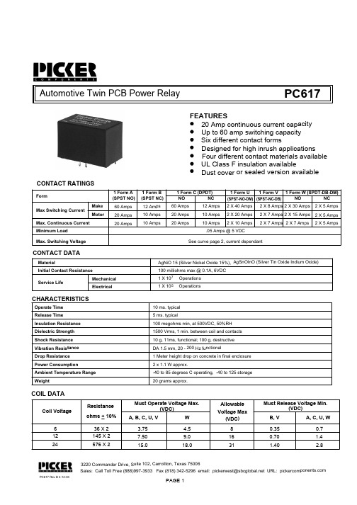
Automotive Twin PCB P ower RelayFEATURES20 Amp continuous current cap acity Up to 60 amp switching capaci ty Four different contact materials available Six different contact formsDesigned for high inrush applic ations UL Class F insulation availablePC617Dust cover or sealed version a vailableFormMax Switching Current Minimum Load1 Form A 60 Amps 20 Amps 1 Form B 12 Amps 10 Amps 10 Amps1 Form C (DPDT)NO NC CONTACT RATINGSCONTACT DATAMaterialInitial Contact Resistance Service LifeMechanical ElectricalAgNiO 15 (Silver Nickel Oxide 15%), AgSnOInO (Silver Tin Oxide Indium Oxide)100 milliohms max @ 0.1A, 6VDC 1 X 1071 X 10520 AmpsOperations OperationsSales: Call Toll Free (888)997-3933 Fax (818) 342-5296 email: pickerwest@ URL: 3220 Commander Drive, Suite 102, Carrollton, T exas 75006(SPST NC)PC617 Rev B 4-14-04PAGE 1(SPST NO)Make Motor60 Amps 20 Amps 20 Amps12 Amps 10 Amps 10 Amps.05 Amps @ 5 VDC1 Form U1 Form V 1 Form W (SPDT-DB-DM)2 X 40 Amps 2 X 20 Amps 2 X 10 Amps2 X 8 Amps 2 X 7 Amps 2 X 7 Amps NO NC 2 X 30 Amps 2 X 15 Amps 2 X 7 Amps2 X 5 Amps 2 X 5 Amps 2 X 5 Amps(SPST-NO-DM)(SPST-NC-DB)Max. Continuous Current See curve page 2, current dependantMax. Switching VoltageCHARACTERISTICSOperate Time 10 ms. typical Release Time Insulation Resistance 5 ms. typical100 megohms min, at 500VDC, 50%RH Dielectric Strength 1500 Vrms, 1 min. between coil and contacts Shock Resistance 10 g, 11ms, functional; 100 g, destructive Vibration Resistance DA 1.5 mm, 20 - 200 Hz functionalPower Consumption 2 x 1.1 W approx.Ambient Temperature Range -40 to 85 degrees C operating, -40 to 125 stora ge Weight20 grams approx.Drop Resistance 1 Meter height drop on concrete in final enclosu re COIL DATAPC617PC617Sales: Call Toll Free (888) 997-3933 F ax (818) 342-5296 email: pickerwest@sbc URL: 3220 Commander Drive, Suite 102, Car rollton, Texas 75006PAGE 2Tolerances +.010 unless otherwise notedNotes:Dimensions in Inches (millimet ers) drawings are 2 X scaleREFERENCE CURVES2 Form A2 Form B2 Form C2 Form U2 Form V2 Form W(29.6)1.165(18).709ORDERING INFORMATIONExample:PC617Model-2CContact FormContact Material-12Nil: AgSnO; C: AgCdO; T: AgSnOInOCoil VoltageSNil: Open Frame; S: Sealed; C: Dust Cover EnclosureT2A, 2B, 2C, 2U, 2V or 2W。
AHRS5600光纤航姿系统

AHRS5600产品简介AHRS5600由三轴一体设计的中等精度光纤陀螺和石英挠性加速度计构成,可作为独立工作的惯性导航系统或捷联罗经。
产品特点结构紧凑的中精度光纤陀螺航姿系统;多种工作模式适用不同应用环境;应用领域大地测绘;车辆定位定向;船用罗经;轨道检测;无人机导航、控制;主要技术指标总体指标:重量:≤2kg;外形:100mm*100mm*96.5mm;供电:9-36V DC;稳态功耗:≤15W;工作温度:-40—+70℃;数据更新频率:200Hz(可定制最高1000Hz);接口:RS422\CAN\网络;连续工作时间:≥12小时;光纤陀螺仪指标:量程:±500°/s;零偏稳定性:≤0.05—0.2°/h(可定制);零偏重复性:≤0.05—0.2°/h(可定制);随机游走系数:≤0.02°/h0.5;标度因数重复性:≤100ppm;标度因数非线性:≤100ppm;带宽:≥500Hz;石英挠性加速度计(含数字采样电路)指标:量程:±10g;零偏稳定性:≤300ug(1秒平均);标度因数稳定性:≤100ppm(-40—+70℃,补后);纯惯性航姿模式指标:初始对准时间:≤5min;初始对准航向精度:0.3°—1°;罗经模式航向精度:0.3°secφ—1°secφ;开环航向保持精度:≤0.1°/h—0.3°/h;水平姿态精度:≤0.05°(RMS)AHRS6500光纤航姿系统产品介绍AHRS6500光纤航姿系统是一款全固态的高精度光纤陀螺航姿参考系统,能够在晃动环境下自主快速初始对准,为运动载体实时提供连续的航向、水平姿态和升沉等信息。
AHRS6500光纤航姿系统可选配内置卫星导航板卡,构成组合航姿系统,也可用于地面车辆、低动态飞行器的定位定向与姿态控制。
产品特点对准时间短;姿态精度高;动态精度高;长期工作性能稳定;应用领域船舶和水下潜器导航;海洋工程测量测绘;船用设备姿态基准;低速飞行器测姿;车辆定位定向;主要技术指标重量:≤3.5kg;外形:140mm*140mm*133mm(不含卫星导航板卡);150mm*140mm*133mm(内置卫星导航板卡);供电:9-36V DC;输出接口:RS422/CAN/以太网;数据更新率:≥200Hz;稳态功耗:≤15W;工作温度:-45—+70℃;工作纬度:南纬70°—北纬70°;启动时间:≤1min;初始对准时间:≤5min;航向精度:≤0.1°(惯性\卫星组合);≤0.06°/h(纯惯性状态);俯仰、横滚精度:≤0.05°(惯性\卫星组合);≤0.03°/h(纯惯性状态);角速率量程:±300°/s;线加速度量程:±10g;MTBF:≥3000h;振动环境:20-2000Hz,6.06g;F1060型光纤陀螺仪F1060型光纤陀螺仪具有启动时间短、体积小、重量轻、高带宽、低功耗、低成本、磁屏蔽性好等优势,在国内同型光纤陀螺仪中综合性能最优。
- 1、下载文档前请自行甄别文档内容的完整性,平台不提供额外的编辑、内容补充、找答案等附加服务。
- 2、"仅部分预览"的文档,不可在线预览部分如存在完整性等问题,可反馈申请退款(可完整预览的文档不适用该条件!)。
- 3、如文档侵犯您的权益,请联系客服反馈,我们会尽快为您处理(人工客服工作时间:9:00-18:30)。
产品特点
+ 增强了BeiDou、GLONASS 和Galileo信号追踪的可用性
+ L1, L2, L2C, B1, B2, E1 和 E5b 信号追踪
+ GLIDE 平滑算法 + RT-2®, ALIGN 和 RAIM 固件
选项 + SPAN® INS 功能
如果你想了解更多关于接收机的信息,请登 录:/products/gnssreceivers/oem-receiver-boards/
• 支持Windows XP、Windows 7 平台
可选固件
• ALIGN • RAIM • SPAN
可选配件
GPS-700 系列天线 • ANT 系列天线 • RF 线缆—5 到 10 米长度 • OEM6 开发套件
浏览更多信息,请登录: /products/gnss -receivers/oem-receiverboards/oem6-receivers/
50 Hz 50 Hz
< 50 s < 35 s
信号重捕获
L1
< 0.5 s (典型值)
L2
< 1.0 s (典型值)
时间精度10
20 ns RMS
测速精度 速度限制11
0.03 m/s RMS 515 m/s
尺寸 重量
46 × 71 × 11 mm <24 g
功率
输入电压
+3.3 V +5%/-3%
自定义API
OEM617具备了应用程序接口(API)功能,基于推荐的API类库,使用标 准的C/C++环境可以开发应用程序并可以直接在接收机平台上运行,消除 了外部硬件系统,减少开发周期,更快地让产品投入市场。
OEM617TM
性能1
物理及电气性能
标准配置
通道配置 120 个通道2
信号跟踪
GPS GLONASS BeiDou Galileo3 SBAS QZSS
接收机
OEM617TM
结构紧凑的,卓越RTK功能的 双频GNSS接收机
产品优势
高精度GNSS,紧凑的尺寸
双频OEM617可以为空间紧凑的产品设计提供高精度的定位功能。形状尺寸与 最流行的OEM615™完全兼容,OEM617提供最有效的方式将强大的GNSS功能产品 快速地推向市场 。
+ 久经考验的NovAtel技术
sales@ 1-800-NOVATEL (U.S. and Canada) or 403-295-4900 中国 0086-21-54452990-8011 欧洲 44-1993-848-736 东南亚和澳大利亚 61-400-883-601
1. 典型值。性能规格受制于GPS系统的特征、美国国防部操作的退化、电离层和对流层的 情况、卫星几何分布、基线长度、多路径效应和存在的有意识或无意识的干扰源
L1,L2,L2C L1,L2 B1,B2 E1,E5b
水平定位精度 (RMS)
单点 L1
1.5 m
单点 L1/L2
1.2 m
SBAS4
0.6 m
DGPS
0.4 m
NovAtel CORRECT
» RT-2
1 cm + 1 ppm
初始化时间
< 10 s
初始化可靠性
>99.9%
测量精度 (RMS) 完全独立的码和载波相位测量 值:
功耗12
GPS L1/L2
<1.0 W
GPS/GLONASS L1/L2 all on
1.1 W 1.2 W
天线接口馈电输出
输入电压 输出电压 最大输出电流
6 VDC-12 VDC 5.0 VDC 200 mA
输入输出连接器
主接口
20-pin 双排公头
天线接口
MCX 母头
通讯接口
Hale Waihona Puke 3 LVTTL最大 921,600 bps
NOVATEL CONNECT™
NovAtel Connect是一个可直 观配置和可视化的工具包,便 于对OEM617进行综合控制
• 易于使用的向导配置指导你 进行定位模式的配置和收集 原始数据
• 详细的视图窗口显示综合的 位置信息
• 平面图和回放文件能够帮助 你查看定位信息和历史配置
• 可通过网络远程控制和监控 OEM617
+ 易于集成 + 低功耗 + 应用程序接口(API)降低了额
外的硬件需要和系统复杂性
超前的设计 OEM617能够接收所有当前的全球导航卫星系统包括GPS、GLONASS、Galileo、 BeiDou和QZSS。在任何条件下,通过优化配置通道提高卫星的可用性。OEM617 还可以通过升级软件来接收未来投入使用的卫星信号,最大程度的提高卫星可 用性和的优化卫星信号使用,并且在未来,确保稳定、高性能的GNSS定位。
2 CAN Bus13
1 Mbps
1 USB
12 Mbps
秒脉冲(PPS)输出
环境
温度 工作温度 存储温度
-40°C to +85°C -55°C to +95°C
湿度
95% 无冷凝
振动
随机振动
MIL-STD 810G
(Cat 24, 7.7g RMS)
正弦振动
IEC 60068-2-6
冲击 震动
ISO 9022-31-06 (25 g) MIL-STD-810G (40 g) Survival (75 g)
• 现场升级固件 • 多路径抑制技术 • 差分 GPS 定位 • 支持 RTCM 2.1, 2.3, 3.0,
3.1, CMR, CMR+ 和 RTCA 差分 • 输出数据类型 NMEA 0183 、NovAtel ASCII 二进制编码 • 辅助选通信号, 包括可配 置的时间同步输出和时间 标记输入 • 可输出驱动外部LED • GLIDE 平滑计算
灵活的设计
具有模块化特性的NovAtel OEM6®固件为用户的应用提供了灵活的配置。OEM617 提供了分米级到厘米级的定位精度,可选升级的OEM6系列软件,包括 NovAtel CORRECT™ 的RTK功能,能提供实时厘米级定位精度、ALIGN®提供精确的 测向和相对定位、GLIDE™可以为分米级pass to pass精度,SPAN可以提供连续的 三维位置、速度、和姿态,同时RAIM增强了GNSS伪距完好性。
2. 跟踪60颗L1/L2卫星 3. 为北斗2阶段设计,兼容B1和B2 4. 只支持GPS. 5. GLONASS L2 P码 6. GLONASS L2C/A码
7. 50 Hz 同时跟踪20颗卫星 8. 典型值.没有历书或星历,没有近似的方位或时间. 9. 典型值.历书和最近保存的星历,近似的方位和时间输入. 10.时间精度不包括偏斜的射频或天线的延时 11.出口限制的最大速度是515m/s 12.典型的功耗值. 13.用户应用
L1 C/A 码 L1 载波相位
L2 P(Y) 码5 L2 载波相位5 L2C 码5 L2C 载波相位6
GPS 4 cm
0.5 mm 8 cm 1 mm 8 cm
1 mm
GLO 8 cm
1 mm 8 cm 1 mm 8 cm
1 mm
最大数据更新率7 原始数据
定位数据 首次定位时间 冷启动8 热启动9
