搬运机器人外文翻译
AGV搬运机器人

Special Industry:Automatic driving in military field,used in battles and land indentification.
Catering Industry:Serve people with beverage,dish or tea.
Advantages
ApplicationБайду номын сангаасField
SHENZHEN MIRCOLOMAY TECHNOLOGY CO.,LTD
Basic Introduction on AGV
AGV: Automated Guided Vehicle .Currently the most common applications are: AGV carrying robots or AGV
manufacture,electronics,textile,papermaking.cigerattes,food,pringting and book publishing.
SHENZHEN MIRCOLOMAY TECHNOLOGY CO.,LTD
The Main Types of AGV
2、Connect to local Area Network and management system,best choice for unmanned factory,automated warehouse and logistics automation.
3、It is widely used in all types of factories,carrying goods and materials,assembly and leading,transfering function and taking place of human labor. it touches many fields as follow:automobile,mechanic
搬运机器人
搬运机器人的机械设计------臂部设计
手臂部件是机械手的重要握持部件。它的作用是支撑腕部和 手部(包括工作或 夹具),并带动他们做空间运动。
搬运机器人的机械设计------机械整体设计
对气动机械手的基本要求是能快速、准确地拾放和搬运物件,这就要 求它们具有高精度、快速反应、一定的承载能力、足够的工作空间和 灵活的自由度及在任意位置都能自动定位等特性
设计气动机械手的原则是:
I. 充分分析作业对象(工件)的作业技术要求,拟定最合理的作业工序和工 艺,满足系统功能要求和环境条件;
设计的搬运机器人的腕部的运 动为一个自由度的回转运动, 运动参数是实现手部回转的角 度控制是在0°~180°范围内。 如图
腕部回转基本结构示 意
搬运机器人的机械设计------腕部设计
腕部的驱动方式采用直接驱动 的方式,由于腕部装在手臂的 末端,所以必须设计的十分紧 凑可以把驱动源装在手腕上。
机器人手部的张合是由双作用单 柱塞液压缸驱动的;而手腕的回 转运动则由回转液压缸实现。将 夹紧活塞缸的外壳与摆动油缸的 动片连接在一起;当回转液压缸 中不同的油腔中进油时即可实现 手腕不同方向的回转。
搬运机器人简介 ------搬运机器人的机械设计
组员:陆真元(PPT演示) 芮荣震(PPT制作) 邵刚(答 辩) 孙明森(资料准备)
目录
搬运机器人的历史 搬运机器人的意义 搬运机器人的机械设计 机械整体设计 执行机构 驱动机构 控制机构
搬运机器人的历史
搬运机器人【transfer robot】 是可以进行自动化搬运作业的工 业机器人,也被称为无人搬运车 或者是AGV。最早的搬运机器 人出现在1960年的美国, Versatran和Unimate两种机器 人首次用于搬运作业。搬运作业 是指用一种设备握持工件,是指 从一个加工位置移到另一个加工 位置。
机器人外文文献翻译、中英文翻译
外文资料robotThe industrial robot is a tool that is used in the manufacturing environment to increase productivity. It can be used to do routine and tedious assembly line jobs,or it can perform jobs that might be hazardous to the human worker . For example ,one of the first industrial robot was used to replace the nuclear fuel rods in nuclear power plants. A human doing this job might be exposed to harmful amounts of radiation. The industrial robot can also operate on the assembly line,putting together small components,such as placing electronic components on a printed circuit board. Thus,the human worker can be relieved of the routine operation of this tedious task. Robots can also be programmed to defuse bombs,to serve the handicapped,and to perform functions in numerous applications in our society.The robot can be thought of as a machine that will move an end-of-tool ,sensor ,and/or gripper to a preprogrammed location. When the robot arrives at this location,it will perform some sort of task .This task could be welding,sealing,machine loading ,machine unloading,or a host of assembly jobs. Generally,this work can be accomplished without the involvement of a human being,except for programming and for turning the system on and off.The basic terminology of robotic systems is introduced in the following:1. A robot is a reprogrammable ,multifunctional manipulator designed to move parts,material,tool,or special devices through variable programmed motions for the performance of a variety of different task. This basic definition leads to other definitions,presented in the following paragraphs,that give acomplete picture of a robotic system.2. Preprogrammed locations are paths that the robot must follow to accomplish work,At some of these locations,the robot will stop and perform some operation ,such as assembly of parts,spray painting ,or welding .These preprogrammed locations are stored in the robot’s memory and are recalled later for continuousoperation.Furthermore,these preprogrammed locations,as well as other program data,can be changed later as the work requirements change.Thus,with regard to this programming feature,an industrial robot is very much like a computer ,where data can be stoned and later recalled and edited.3. The manipulator is the arm of the robot .It allows the robot to bend,reach,and twist.This movement is provided by the manipulator’s axes,also called the degrees of freedom of the robot .A robot can have from 3 to 16 axes.The term degrees of freedom will always relate to the number of axes found on a robot.4. The tooling and frippers are not part the robotic system itself;rather,they are attachments that fit on the end of the robot’s arm. These attachments connected to the end of the robot’s arm allow the robot to lift parts,spot-weld ,paint,arc-weld,drill,deburr,and do a variety of tasks,depending on what is required of the robot.5. The robotic system can control the work cell of the operating robot.The work cell of the robot is the total environment in which the robot must perform itstask.Included within this cell may be the controller ,the robot manipulator ,a work table ,safety features,or a conveyor.All the equipment that is required in order for the robot to do its job is included in the work cell .In addition,signals from outside devices can communicate with the robot to tell the robot when it should parts,pick up parts,or unload parts to a conveyor.The robotic system has three basic components: the manipulator,the controller,and the power source.A.ManipulatorThe manipulator ,which does the physical work of the robotic system,consists of two sections:the mechanical section and the attached appendage.The manipulator also has a base to which the appendages are attached.Fig.1 illustrates the connectionof the base and the appendage of a robot.图1.Basic components of a robot’s manipulatorThe base of the manipulator is usually fixed to the floor of the work area. Sometimes,though,the base may be movable. In this case,the base is attached to either a rail or a track,allowing the manipulator to be moved from one location to anther.As mentioned previously ,the appendage extends from the base of the robot. The appendage is the arm of the robot. It can be either a straight ,movable arm or a jointed arm. The jointed arm is also known as an articulated arm.The appendages of the robot manipulator give the manipulator its various axes of motion. These axes are attached to a fixed base ,which,in turn,is secured to a mounting. This mounting ensures that the manipulator will in one location.At the end of the arm ,a wrist(see Fig 2)is connected. The wrist is made up of additional axes and a wrist flange. The wrist flange allows the robot user to connect different tooling to the wrist for different jobs.图2.Elements of a work cell from the topThe manipulator’s axes allow it to perform work within a certain area. The area is called the work cell of the robot ,and its size corresponds to the size of the manipulator.(Fid2)illustrates the work cell of a typical assembly ro bot.As the robot’s physical size increases,the size of the work cell must also increase.The movement of the manipulator is controlled by actuator,or drive systems.The actuator,or drive systems,allows the various axes to move within the work cell. The drive system can use electric,hydraulic,or pneumatic power.The energy developed by the drive system is converted to mechanical power by various mechanical power systems.The drive systems are coupled through mechanical linkages.These linkages,in turn,drive the different axes of the robot.The mechanical linkages may be composed of chain,gear,and ball screws.B.ControllerThe controller in the robotic system is the heart of the operation .The controller stores preprogrammed information for later recall,controls peripheral devices,and communicates with computers within the plant for constant updates in production.The controller is used to control the robot manipulator’s movements as well as to control peripheral components within the work cell. The user can program the movements of the manipulator into the controller through the use of a hard-held teach pendant.This information is stored in the memory of the controller for later recall.The controller stores all program data for the robotic system.It can store several differentprograms,and any of these programs can be edited.The controller is also required to communicate with peripheral equipment within the work cell. For example,the controller has an input line that identifies when a machining operation is completed.When the machine cycle is completed,the input line turn on telling the controller to position the manipulator so that it can pick up the finished part.Then ,a new part is picked up by the manipulator and placed into the machine.Next,the controller signals the machine to start operation.The controller can be made from mechanically operated drums that step through a sequence of events.This type of controller operates with a very simple robotic system.The controllers found on the majority of robotic systems are more complex devices and represent state-of-the-art eletronoics.That is,they are microprocessor-operated.these microprocessors are either 8-bit,16-bit,or 32-bit processors.this power allows the controller to be very flexible in its operation.The controller can send electric signals over communication lines that allow it to talk with the various axes of the manipulator. This two-way communication between the robot manipulator and the controller maintains a constant update of the end the operation of the system.The controller also controls any tooling placed on the end of the robot’s wrist.The controller also has the job of communicating with the different plant computers. The communication link establishes the robot as part a computer-assisted manufacturing (CAM)system.As the basic definition stated,the robot is a reprogrammable,multifunctional manipulator.Therefore,the controller must contain some of memory stage. The microprocessor-based systems operates in conjunction with solid-state devices.These memory devices may be magnetic bubbles,random-access memory,floppy disks,or magnetic tape.Each memory storage device stores program information fir or for editing.C.power supplyThe power supply is the unit that supplies power to the controller and the manipulator. The type of power are delivered to the robotic system. One type of power is the AC power for operation of the controller. The other type of power isused for driving the various axes of the manipulator. For example,if the robot manipulator is controlled by hydraulic or pneumatic drives,control signals are sent to these devices causing motion of the robot.For each robotic system,power is required to operate the manipulator .This power can be developed from either a hydraulic power source,a pneumatic power source,or an electric power source.There power sources are part of the total components of the robotic work cell.中文翻译机器人工业机器人是在生产环境中用以提高生产效率的工具,它能做常规乏味的装配线工作,或能做那些对于工人来说是危险的工作,例如,第一代工业机器人是用来在核电站中更换核燃料棒,如果人去做这项工作,将会遭受有害放射线的辐射。
Robots机器人 中英文翻译
RobotsA robot is an automatically controlled, reprogrammable, multipurpose, mani pulating machine with several reprogrammable axes, which may be either fixed in place or mobile for use in industrial automation applications.The key words are reprogrammable and multipurpose because most single-purpose machines do not meet these two requirements.The term”reprogrammabl e” implies two things:The robot operates according to a written program can b e rewritten to accomdate a variety of manufacturing tasks. The term “multipurp ose” means that the robot can perform many different functions, depending on the program and tooling currently in use.Over the past two decades,the robot has been introduced into industry to perform many monotonous and often unsafe operations. Because robots can per form certain basic tasks more quickly and accurately than humans, they are bei ng increasingly used in various manufacturing industries.Structures of RobotsThe typical structure of industrial robots consists of 4 major components: the manipulator, the end effector, the power supply and control syterm.The manipulator is a mechanical unite that provides motions similar to those of a human arm. It often has a shoulder joint,an elbow and a wrist. It can rotate or slide, strech out and withdraw in every possible direction with certain flexibility.The basic mechanical configurations of the robot manipulator are categorized as Cartesian, cylindrical, spherical and articulated.A robot with a Cartesian geometry can move its gripper to any position within the cube or rectangle defined as its working volum.Cylindrical coordinate robots can move the gripper within a volum that is described by a cylinder. The cylindrical coordinate robot is positioned in the work area by two linear movements in the X and Y directions and one angular rotation about the Z axis.Spherical arm geometry robots have an irregular work envelop. This type of robot has two main variants,vertically articulated and horizontally articulated.The end effector attaches itself to the end of the robot wrist, also called end-of-arm tooling.It is the device intended for performing the designed operations as a human hand can.End effectors are generally custom-made to meet special handling requirements. Mechanical grippers are the most commonly used and are equipped with two or more fingers.The selection of an appropriate end effector for a special application depends on such factors as the payload, enviyonment,reliability,and cost.The power supply is the actuator for moving the robot arm, controlling the joints and operating the end effector. The basic type of power sources include electrical,pneumatic, and hydraulic. Each source of energy and each type of motor has its own characteristics, advantages and limitations. An ac-powered motor or dc-powered motor may be used depending on the system design and applications. These motors convert electrical energy into mechanical energy to power the robot.Most new robots use electrical power supply. Pneumatic actuators have been used for high speed. Nonservo robots and are often used for powering tooling such as grippers. Hydraulic actuators have been used for heavier lift systems, typically where accuracy was not also requied.The contro system is the communications and information-processing system that gives commands for the movements of the robot. It is the brain of the robot; it sends signals to the power source to move the robot arm to a specific position and to the end effector.It is also the nerves of the robot; it is reprogrammable to send out sequences of instructions for all movements and actions to be taken by the robot.A open-loop controller is the simplest for of the control system, which controls the robot only by foolowing the predetermined step-by-step instructions.This system dose not have a self-correcting capability.A close-loop control system use feedback sensors to produce signals that reflct the current states of the controed objects. By comparing those feedback signals with the values set by the programmer, the close-loop controller can conduct the robot to move to the precise position and assume the desired attitude, and the end effector can perform with very high accuracy as the close-loop control system can minimize the discrepancy between the controlled object and the predetermined references.Classification of RobotIndustrial robots vary widely in size,shape, number of axes,degrees of freedom, and design configuration. Each factor influence the dimensions of the robot’s working envelop or the volume of space within which it can move and perform its designated task. A broader classification of robots can been described as below.Fixed-and Variable-Sequence Robots. The fixed-sequence robot (also called a pick-and place robot) is programmed for a specific sequence of operations. Its movements are form point to point, and the cycle is repeated continuously.The variable-sequence robot can be programmed for a specific sequence of operations but can be programmed to perform another sequence of operation.Playback Robot. An operator leads or walks the playback robot and its end effector through the desired path. The robot memorizes and records the path and sequence of motions and can repeat them continually without any further action or guidance by the operator.Numerically Controlled Robot. The numerically controlled robot is programmed and operated much like a numerically controlled machine. The robot is servocontrolled by digital data, and its sequence of movements can be changed with relative ease.Intelligent Robot. The intelligent robot is capable of performing some of the functions and tasks carried out by huanbeings.It is equipped with a variety of sensors with visual and tactile capabilities.Robot ApplicationsThe robot is a very special type of productin tool; as a result, the applications in which robots are used are quite broad. These applications can be grouped into three categories: material processing, material handling and assembly.In material processing, robots use tools to process the raw material. For example, the robot tools could include a drill and the robot would be able to perfor drilling operaytions on raw material.Material handling consists of the loading, unloading, and transferring of workpieces in manufacturing facilities. These operations can be performed relatively and repeatedly with robots, thereby improving quality and scrap losses.Assembly is another large application area for using robotics. An automatic assembly system can incorporate automatic testing, robot automation and mechanical handling for reducing labor costs, increasing output and eliminating manual handling concers.机器人机器人是一种自动控制的、可重复编程的、多功能的、由几个可重复编程的坐标系来操纵机器的装置,它可以被固定在某地,还可以是移动的以在工业自动化工厂中使用。
搬运机器人介绍ppt课件
AGV
AGV与计算机控制的全自动化生产装配系统有机地连接,可降低 制造成本,提高作业安全性,提高劳动生产效率,并且节约能源保护环 境。促进了企业的技术进步同时也降低了物料运输成本,有效地解放 了劳动生产力,减轻了劳动强度,提高了企业的安全性,降低了企业 事故的发生率。AGV在现代制造车间中高效准确地进行物料搬运操作 具有较大的应用价值。
装置构造
驱动装置:由车轮,减速器,制动器,电动机及速度控制器等部分 组成,并由计算机或者人工进行控制,它是一个伺服驱动的变速控制 系统。 转向装置:双轮差速转向。 移载装置:装卸货物。 控制与通信系统:车上控制器和地面控制器 安全装载:包括多级硬件和软件。
按引导方式来分
坐标自动导引车 电磁自动导引车 磁带自动导引车 光学自动导引车 激光自动导引车 惯性自动导引车 视觉自动导引车
组成
一般组成:导向系统,车体,蓄电池,充电装置,驱动装置,转向 装置,移载装置,控制与通信系统,安全装置。 导向系统是核心部分,用来控制AGV小车的行驶方向,沿着规定的 路径行驶并完成一系列指定任务。 车体由车架,减速器,电动机,车轮等组成,车架常采用焊接刚结 构,有足够的韧性,车身由铝合金构造,耐腐蚀,而且重量轻,美观。 蓄电池由直流或交流工业蓄电池,米克力美的电池可达到48小时重 载不间断工作,完美实现24X7小时连续作业。
超声波检测技术
超声检测技术是利用墙面或类似物体对超声波的反射信号进行定 位导向,因而在特定的环境下可以提高路径的柔性。同时由于不需要 设置反射镜面,也降低了导向成本。但是,当运行环境的反射情况比 较复杂时,应用还十分困难。
图像识别技术
采用图像识别技术有2种方法,其一就是利用CCD系统动态摄取运 行路径周围环境图像信息,并与拟定的运行路径周围环境图像数据库 中的信息进行比较,从而确定当前位置及对继续运行路线做出决策。 这种方法不要求设置任何物理路径,因此,在理论上是最佳的柔性导 向。 但实际应用还存在问题,主要是实时性差和运行路径周围环境信 息库的建立困难。其二就是标识线图像识别方法,它是在AGV运行所 经过的地面上画1条标识明显的导向标线,利用CCD系统动态摄取标 线图像并识别出AGV相对于标线的方向和距离偏差,以控制车辆沿着 设定的标线运行。
搬运机器人毕业设计 (含外文翻译)
1 前言众所周知随着社会的不断发展,各行各业的分工越来越明细,尤其是在现代化的大产业中,有的人每天就只管拧一批产品的同一个部位上的一个螺母,有的人整天就是接一个线头,人们感到自己在不断异化,各种职业病逐渐产生,于是人们强烈希望用某种机器代替自己工作,因此人们研制出了机器人,用以代替人们去完成那些单调、枯燥或是危险的工作。
搬运机器人的显著特点是无人驾驶,它装备有自动导向系统,可以保障系统在不需要人工引航的情况下就能够沿预定的路线自动行驶,将货物或物料自动从起始点运送到目的地。
1搬运机器人的另一个特点是柔性好,自动化程度高和智能化水平高,它的行驶路径可以根据仓储货位要求、生产工艺流程等改变而灵活改变,并且运行路径改变的费用与传统的输送带和刚性的传送线相比非常低廉。
搬运机器人一般配备有装卸机构,可以与其他物流设备自动接口,实现货物和物料装卸与搬运全过程自动化。
此外,搬运机器人还具有清洁生产的特点,依靠自带的蓄电池提供动力,运行过程中无噪声、无污染,可以应用在许多要求工作环境清洁的场所。
搬运机器人作为一种成熟的产品和技术在发达国家已经广泛应用,对企业提高生产效率降低成本提高产品质量提高企业生产管理水平起到了显著的作用。
随着工业自动化的发展,国内外的应用和需求越来越强烈,已经约有千台AGV 在使用,而且市场在逐渐扩大。
根据初步市场调查分析,今后5 年内,国内各行业对AGV 需求量可达数千台,年产值接近2 亿元,经济效益十分可观。
1.1 国内外的发展现状总结一下,我们认为,机器人有三个发展阶段,那么也就是说,我们习惯于把机器人分成三类,一种是第一代机器人,那么也叫示教再现型机器人,它是通过一个计算机,来控制一个多自由度的一个机械,通过示教存储程序和信息,工作时把信息读取出来,然后发出指令,这样的话机器人可以重复的根据人当时示教的结果,再现出这种动作,比方说汽车的点焊机器人,它只要把这个点焊的过程示教完以后,它总是重复这样一种工作,它对于外界的环境没有感知,这个操作力的大小,这个工件存在不存在,焊的好与坏,它并不知道,那么实际上这种第一代机器人,也就存在它这种缺陷。
机器人外文翻译(中英文翻译)
机器人外文翻译(中英文翻译)机器人外文翻译(中英文翻译)With the rapid development of technology, the use of robots has become increasingly prevalent in various industries. Robots are now commonly employed to perform tasks that are dangerous, repetitive, or require a high level of precision. However, in order for robots to effectively communicate with humans and fulfill their intended functions, accurate translation between different languages is crucial. In this article, we will explore the importance of machine translation in enabling robots to perform translation tasks, as well as discuss current advancements and challenges in this field.1. IntroductionMachine translation refers to the use of computer algorithms to automatically translate text or speech from one language to another. The ultimate goal of machine translation is to produce translations that are as accurate and natural as those generated by human translators. In the context of robots, machine translation plays a vital role in allowing them to understand and respond to human commands, as well as facilitating communication between robots of different origins.2. Advancements in Machine TranslationThe field of machine translation has experienced significant advancements in recent years, thanks to breakthroughs in artificial intelligence and deep learning. These advancements have led to the development of neural machine translation (NMT) systems, which have greatly improved translation quality. NMT models operate by analyzinglarge amounts of bilingual data, allowing them to learn the syntactic and semantic structures of different languages. As a result, NMT systems are capable of providing more accurate translations compared to traditional rule-based or statistical machine translation approaches.3. Challenges in Machine Translation for RobotsAlthough the advancements in machine translation have greatly improved translation quality, there are still challenges that need to be addressed when applying machine translation to robots. One prominent challenge is the variability of language use, including slang, idioms, and cultural references. These nuances can pose difficulties for machine translation systems, as they often require a deep understanding of the context and cultural background. Researchers are currently working on developing techniques to enhance the ability of machine translation systems to handle such linguistic variations.Another challenge is the real-time requirement of translation in a robotic setting. Robots often need to process and translate information on the fly, and any delay in translation can affect the overall performance and efficiency of the robot. Optimizing translation speed without sacrificing translation quality is an ongoing challenge for researchers in the field.4. Applications of Robot TranslationThe ability for robots to translate languages opens up a wide range of applications in various industries. One application is in the field of customer service, where robots can assist customers in multiple languages, providing support and information. Another application is in healthcare settings, where robots can act as interpreters between healthcare professionals and patientswho may speak different languages. Moreover, in international business and diplomacy, robots equipped with translation capabilities can bridge language barriers and facilitate effective communication between parties.5. ConclusionIn conclusion, machine translation plays a crucial role in enabling robots to effectively communicate with humans and fulfill their intended functions. The advancements in neural machine translation have greatly improved translation quality, but challenges such as language variability and real-time translation requirements still exist. With continuous research and innovation, the future of machine translation for robots holds great potential in various industries, revolutionizing the way we communicate and interact with technology.。
搬运工机器人(AGV)简介
搬运工(AGV)简介搬运工(AGV)简介搬运工(Automated Guided Vehicle,简称AGV)是一种能够自主移动并执行物料运输任务的。
它们通常被用于工业环境中,用于搬运重物、运输物料和组织生产流程。
本文将详细介绍搬运工的定义、原理、种类、应用领域以及前景展望等内容。
一、定义搬运工是一种能够通过自主导航系统在预定路径上移动并执行搬运任务的。
它们通常具备传感器、导航系统和执行器等组件,能够感知周围环境、规划路径并执行搬运操作。
搬运工可以自主决策、避开障碍物,以提高物料搬运的效率和准确性。
二、原理搬运工的核心原理是通过激光、超声波、视觉等传感器感知环境,并利用导航算法规划最佳路径。
会根据实时的环境数据进行决策,避开障碍物、遵循交通规则,以确保搬运任务的顺利完成。
同时,搬运工还配备执行器,可以通过机械臂、升降平台等装置来搬运物料。
三、种类根据不同的搬运需求,搬运工有多种不同的类型。
常见的几种类型包括:1.叉车型AGV:类似传统叉车的,主要用于搬运货物。
它们通常具备叉手,能够承载和抬升重物,并在仓库等环境中自动完成物料的搬运任务。
2.输送带型AGV:这类通常安装有一个移动的输送带,用于搬运物料。
它们可在生产线上移动,从而将物料从一个工作站传输到另一个工作站。
3.拖车型AGV:这类通常是用来搬运物料车或货架。
它们一般配备牵引装置,可以将货物拖动到需要的位置。
4.自由导引型AGV:这类没有固定路径,可以通过自主导航系统在任何场所自由移动。
它们通常配备地图导航系统或者虚拟引导线等技术来实现自主导航。
四、应用领域搬运工广泛应用于各个行业,特别是需要大量物料运输的工业环境。
以下是几个主要的应用领域:1.仓储物流:搬运工可以在仓库中自动地搬运货物。
它们可以通过与仓库管理系统(WMS)或物料处理系统(MHS)的集成来实现自动化的搬运任务。
2.制造业:在制造业中,搬运工可以帮助完成装配、运输和包装等任务。
(完整word版)码垛机器人外文文献及翻译
外文文献:Technology status and Development trend of Stacking crane1 OverviewStacking crane is a special crane as of version of the warehouse and developed to appearSpecial crane, commonly referred to as the pile of chop machine, piling machine is three-dimensional storehouse of the most important lifting transportation equipment, represents the sign of three-dimensional warehouse characteristics. Its main use is:In the top shelf of the warehouse in orbit, will be located at the mouth of the goods in goods mesh; Or the opposite, take out loans in case the goods to the mouth of roadway, the loading and unloading finish homework. 20 the early 70 s, China began to research the type of machine of roadway when the three-dimensional warehouse, according to not complete count, up to now has been built more than three hundred seats.Stacking machine as a three-dimensional storehouse of the most important lifting transportation equipment, also obtained fast development.2 version of the present situation of stacking crane technology.According to the current machinery industry standard, the position of the stacking crane classification of ways. E.g. by supporting mode, use, the method of control, structure, operation such as classified track. But no matter what type of stacking machine, is general by the mobile mechanism, level of lifting mechanism, manifest Taiwan and goods fork institutions, frame and electrical equipment, and other basic parts.In the present application of three-dimensional warehouse, stacking machine is the most common in the form of the structure and operation track classification.2.1 version of the good way of spider crane structure From the structure form difference at present in the warehouse stacker has a double set on structure and single pillar structure.2.1.1 double pillar stacker.Double post the stacker frame structure by two root made on the beams, and to form a rectangle beam under the framework. Pillar form well pipe and pipe. Square tube and be lifting guide rail, pipe additional hoisting guide double pillar stacker the biggest advantage is the strength and the brush sex are quite good, and smooth operation. General for lifting height, weight and higher up large speed high level of three-dimensional storehouse stacker, many with double pillar structure, double pillar stackers lifting mechanism, widespread use of the chain transmission, by motor reducer drive sprockets rotation, through the chain traction machine parts made on or along the hoisting guide for lifting movement.Due to the chain transmission used more closed chain or balance by empty asked size limit device, transmission and decorate a complicated. But positioning precision.2.1.2 single pillar stacker.Single pillar of stacker frame structure by a root of the pillar and beam. Pillar used more larger h-beam or welding production, pillar additional guide. The weight of the lighter, consume little material, so manufacturing relatively low cost, but the rigid is a bit poor. Because parts of Taiwan and the goods on the eccentricity of the opposite effect, and walk, the braking force level from the effect, make single pillar stacker in used on have limitations. Not suitable for lifting weight and the running speed of the high level of stacking machine. Single pillar stackers hoisting structure, the widespread use of the wire rope transmission, by motor reducer drive drum rotating, through the wire rope traction machine parts made on or along the lifting rails for lifting movement. For wire rope transmission, transmission and decorate relatively easy, but positioning accuracy is a bit poor.Version 2.2 of stacking crane to track the performance Stacker level drive general installation in stacker next beam, through the electricityMachine speed reducer drive wheel rotation, make stacker level concerning the direction. This ground driving way most common use. General use two bearing wheel, and along the laying on the ground track (usually also called to rail) operation. Through the bottom two groups of level round orbit direction, the top two groupsin stacker guide wheel along in orbit (usually also called day rail) operation auxiliary oriented. According to the running track form difference, there is a straight line type stacker and curve operation type stacking machine.2.2. L straight lines type stacking machine.Straight line type stacker can only be in the roadway straight orbit, unable to convert roadways. Only through the other transportation equipment of transformation, such as stacker car transport. Straight line type stacker can realize the operation, and can satisfy the loading and unloading higher frequency three-dimensional storehouse homework, most widely used.2.2.2 curve operation type stacking machine.Curve operation type stacking locomotive wheels and the beam under the vertical axis of the hinged, can be in the ring or other curve orbit, can go curve, not through the other transportation equipment can then from a roadway to transfer to another roadways. Such stacker usually also called transition stacker. Curve operation type stacker in used on have limitations, only appliesto the loading and unloading frequency low three-dimensional storehouse. Because not only by the turning radius to the limit, and turning special slow speed, and can't meet the person library of frequency and high warehouse operation.3. The position of the roadway stacking crane development trend.Along with the development of modern industrial production, stacking crane technology of version continuously improved and perfected. The world's major industrial countries starting point on the development of new products and reliable performance and high on the operation on pay more attention to the practicality and safety.In stacker, we shall see and world advanced nation gap, summarizing the experience find out the deficiency, break traditional ideas, has introduced new appearance and higher performance stacker. In make stacking machine has higher precision at the same time, increase speed to get shorter operation cycle and more production ability.Believe that, through our continuous efforts more high speed, safe and reliable heapwhen the machine will continue to digest imported from abroad domestic, make the position of stacking crane development roadway to an update to the stage.中文翻译:有轨巷道堆垛机技术现状及发展趋势1 概述有轨巷道堆垛起重机是随着立体仓库的出现而发展起来的专用起重机,通常简称为堆剁机,堆垛机是立体仓库中最重要的起重运输设备,是代表立体仓库特征的标志。
机械手外文翻译

机械手外文翻译LG GROUP system office room 【LGA16H-LGYY-LGUA8Q8-LGA162】本科毕业设计(论文)外文翻译(附外文原文)学院:机械与控制工程学院课题名称:搬运机械手的结构和液压系统设计专业(方向):机械设计制造及其自动化(机械装备)班级:学生:指导教师:日期: 2015年3月10日Proceedings of the 33rd Chinese Control ConferenceJuly 28-30, 2014, Nanjing, ChinaThe Remote Control System of the ManipulatorSUN Hua, ZHANG Yan, XUE Jingjing , WU Zongkai College of Automation, Harbin Engineering University, Harbin 15000E-mail:Abstract: A remote control system of the 5 degree of freedom manipulator was designed. This manipulator was installed into ourmobile robot to constitute a remote rescue robot. The Denavit-Hartenberg method was used to establish the kinematic models and the path planning of the manipulator was researched. The operator could remote control the manipulator by the interactive interface of PCwhich could display moving picture and various data of the manipulator. The servos of the manipulator were controlled by the slave FPGA controller. In addition, the slave FPGA controller communicated withthe PC via the wireless communication module. Owing to the embedded Nios II program and IP (Intellectual Property) core generating PWM waves in FPGA, the system could control the multiple servos fast and flexible. In order to achieve real-time operation and simulation, the interactive interface was established by the mixed programming of VC and MATLAB.Key Words: The manipulator; Remote control; Denavit-Hartenberg; FPGA; Human-computer interaction1 IntroductionWith the development of the microelectronic technique and the computer technology, the manipulator has become essential equipment in the manufacturing industry. As we all known, the manipulator isusually applied to accomplish dull, onerous and repeated physical work, especially used to substitute the manual operation under the dangerous and the hazardous environment such as the corrosion and the high temperature.In this paper, the manipulator was installed our mobile robot. The tele-operation system of this manipulator was designed. The whole system is onstituted by PC and slave FPGA. The operator can remote control the manipulator by PC. The wireless communication was used for transmitting data between PC and FPGA. FPGA is controller of the the manipulator in the mobile robot. FPGA has the abundant internal resource and IP cores. And a central control option was built via an embedded Nios II program and an IP core in FPGA. Furthermore, Verilog language was adopted to design the IP core which generated digital PWM waves for controlling the manipulator. Therefore, this system could reach higher precision and easy to debug.MATLAB software was adopted to build the kinematic models of manipulator. And using D-H (the acronym of Denavit-Hartenberg) method to solve the forward and inverse kinematic equations of the manipulator, to analyze the motivation, to plan and track themotion’s path.In addition, a good interface of human-computer interaction was enhanced in the remote control system of the manipulator in PC. Moreover, the manipulator simulation technology was built by using the mixed programming of VC and MATLAB. Thus, the motion choreographs was got quickly and easily, also greatly saved time and cut the cost.2 Manipulator Model and Path PlanningAt first, the motion model of the manipulator was built. Then, the kinematic simulation and its path planning were researched. These works provided the foundation for the design of the remote control system of the manipulator.Motion Model of the ManipulatorThe manipulator was regarded as an open loop kinematic chain. It was constituted by five rotary joints. And its one end was fixed on a base while the other end was used to achieve the ability of grabbing. Therefore, it is better to establish a chain coordinate frame as shown in . The terminal position and attitude was determined via usingforward kinematic equation after knowing the rotating angle of every joint. The D-H parameter table shown as Table 1 was established by using the frames in .Coordinate frames of mechanical armTable 1 D-H Parameters of the Robot ArmDue to D-H method:T =T T +1T +1T =(TT T +1−TT T +1TT T +1TT T TT T +1TT T 0T T −TT T −TT T T T +1TT T +1TT T TT T +1TT T 00TT T TT T T T +101)Where C T T +1=cos T T +1 , S T T +1=sin T T +1 , C T T =cos T T , S T T =sin T T . The transformation matrix of every joint was given byequation (2).T 10=(cos T 1sin T 1sin T 1cos T 1000000001001) T 21=(cos T 2−sin T 200001T 1−sin T 2−cos T 2000001) T 32=(cos T 3−sin T 3sin T 3cos T 3000000001T 201) T 43=(cos T 4−sin T 40000−1−T 3sin T 4cos T 4000001) T 54=(cos T 5−sin T 5sin T 5cos T 5000000001T 401) T 50=(T T T T T T T T T T T T T T T T T T T T 00T T T T 01)=T 10T 2∗1T 3∗2T 4∗3T 5∗4 (2)Where unit vector T →,T →,T → in equation (2) was T→=TTTTTT , T →=TTTTTTTTTTT , T →=TTTTTTTT , T→=TTTTTTTT . Parameters of mechanical arm were given by T 1=85mm , T 2=116mm , T 3=85mm , T 4=95mm . Therefore the forward kinematicequation was determined by taking every parameter in equation (3).T 50=(180TT 1T (T 2+T 3)+116TT 1TT 2180TT 1T (T 2+T 3)+116TT 1TT 285+116TT 2+180T (T 2+T 3)) (3)In practical application, the manipulator was adopted to grabobjects. This required that the fixed position was given from terminalto target location. That was the inverse kinematic analysis ofmanipulator. Inverse transformation was used to determine angle of every rotary joint toward the established coordinates. And the used method of inverse transformation was the common method to solve such problem (this method also known as algebraic method).Using inversetransformation T T T −1−1separately to the left multiplication withT =50T 10T 2∗1T 3∗2T 4∗3T 5∗4 , the angle of every rotary joint (T 1 T 2 T 3 T 4 T 5)was determined. Owing to these results, the rotary angles (T 1T 2T 3)at terminal position of manipulator were totally decided by the target position [T T T T T T ]. Angle T 4 was used to change terminal attitude of the manipulator and it was changed by the known normal vector. However, angle T 5, was decided by the size of target object.Motion Simulation of the ManipulatorThe manipulator model was built and simulated via MATLAB toolbox. We could verify the rationality of the mathematical model. While the MATLAB model was established by table 1 and shown asMATLAB simulation of the manipulatorComparing to the and , the simulation model of the manipulator was coincided to the reference frame model. That was to say, the given coordinate frame was correct. These results also could be proved by the determined inverse kinematic equations via MATLAB shown in the table (2) and table (3).The target position was solved by forward kinematics. After that, the rotary angles were calculated by inverse kinematical equation. It turned out that these rotary angles coincided to the given angles. Therefore, these results verified the correctness of forward and inverse kinematical equation.Table (2) Forward Kinematics AnalyzeTable (3) Inverse Kinematics Analyze3 Path Planning of the ManipulatorThe total displacement of joint was calculated by inversekinematical equation when the manipulator moved to new position. Thus, the manipulator could move to new position. Although the manipulator finally moved to the expected position in such condition, the motion of the manipulator between these two points was unknown. Due to space limitations, motion and some certain position requirements, the manipulator was often unable to move as the above mentioned method. Therefore, the motion path was designed to coincide with the limited conditions.In this paper, we could use these certain limitations to decide some expected points. And these expected points were used to match the planning path of the manipulator’s movement. Owing to the planning path, coordinate in every part could be calculated. The rotary angleof every joint was calculated via inverse kinetical equation and these angles realized the movement of planning path. Movement of the manipulator was shown in (Where‘’ represented the points would be p assed by the manipulator;‘*’represented the expected points of every segment; ‘-’represented path planning of the manipulator). In , we could seethat the motion of the manipulator passed every planning point and the movement path coincided to the planning path.The path planning simulation of the manipulator4 Remote Control System of the Manipulato rThe remote control system of the manipulator contains the main PC and the slave FPGA controller using DE2 Board of ALTER Company. The motors of the manipulator were controlled by multipath PWM waves. And the PWM waves were generated by IP core. The FPGA controller Communicated with PC via wireless serial port. While in the PC interaction, the operator could observe the move of the manipulator in real-time and tele-control the motion of the manipulator. Also every movement of manipulator could be observed in advance via thesimulation technique. The general design of the manipulator remote control system was shown in .The block diagram of the remote control systemControl Mode of the ManipulatorThere were two control modes of the manipulator. One mode is thatthe inverse kinematical equations are calculated by FPGA straightly to determine angle of every rotary joint. Thus, the control of the manipulator was achieved. The advantage of this mode is more direct and independent to finish the control of the manipulator without the external devices. At the same time, this mode has large quantities of calculations, which occupy more internal storage and running time of FPGA. Resources of FPGA are wasted under this mode.The other mode accomplished the control of the manipulator by using VC and MATLAB in PC. Using VC and MATLAB finished a large number of complex calculations and determined angle of every rotary joint. And the angle results were transmitted to FPGA in order to accomplish the control of the manipulator. This manner saved lots of internal storage and running time. In addition, FPGA could finish other works underthis mode. But the manipulator was not under fast control in this mode.In this system, a new mode was adopted in the manipulator remote control system depending on the advantages of the two modes. Specifically, when the manipulator accomplished the specified and repeated movement the former mode was adopted under direct control by FPGA. When the manipulator wanted to achieve new motions the latter mode was used to be commanded by orders from PC. This new mode was made good use of advantages of the two modes in the above. And this new mode lightened computational burden and improved workingefficiency of the manipulator.SOPC Design for the Remote Control SystemMovement of the manipulator was controlled by servos. And the servos were controlled by PWM waves with the cycle of 20ms. Pulse width of these PWM waves was ~ corresponding to the rotary angle of servo with-90 degree to 90 degree. High precision of PWM waves were generated by IP core via Verilog in this system. The results were shown in . PWM waves controlled rotary angles of the servos via the servo drivers.The PWM IP coreMultiple of IP cores were able to be downloaded into FPGA. Andmultiple PWM waves with high precision were generated in the output. As shown in , the pulse width of these waves could be settled byprogram of Nios II. The movement of the manipulator was more flexible and in higher precision in this system.The IP cores generating PWM waveThe movement of the manipulator was accomplished by the duty ratio of PWM waves. Formula (4) inverted rotary angle T T to thecorresponding amount of the duty ratio of PWM waves. The duty ratio of PWM waves corresponded to the Nios II output.TTT T =1000000−(T T ∗50000+75000) (4) Wireless serial of 9600 baud rate was used to transmit thecoordinate and the angle information from host computer to FPGA. After that, the data and orders were analyzed by FPGA Then FPGA transmitted the movement results to interactive interface of host computer via wireless transition model. This communication was realized through adding UVRT communication protocol to FPGA.The Interactive Interface of the Remote Control SystemThe interactive interface of the remote control system was shown in . There were some functions in the interactive interface: videoobservation, the manipulator control and the simulation modeling. At first, the manipulator video could be seen from camera tointeractive interface. The operator could monitor the manipulator in real-time.Secondly, the angle and the coordinate could be set in control zone of the interactive interface. The angle of the manipulator could beset independently to each single joint. In addition, the angle settingcould be shown in real-time in the list of interactive interface (as shown in . In the set of coordinates, judging of coordinate setting assured that the total coordinates could achieve to the target points. Thus the manipulator could be controlled to move in the settled path depend on the angle information.Lastly, the MATLAB robot toolbox was embedded into this interactive interface. One interface was integrated both the control andsimulation of the manipulator. MATLAB robot toolbox was directly used by interactive interface in the manipulator modeling. Each group of information was simulated separately in order to detect whether each movement was correct. And the general simulation could test whether movement arrangement of the manipulator was reasonable. Combining with multiple simulation methods made the movement arrangement more flexible, the operation of the manipulator simpler and interface interaction more perfect.The interactive interface of the manipulator5 Experiment and SimulationIn order to verify properties of the remote control system of the manipulator, experiments of the system were under way and were comparing to the simulation system. To be specific, manipulator modeling was built by interactive interface and a group of coordinates could be designed. we could see that the manipulator modeling and control of the interactive interface design comforted to the design requirement. The comparing between experiment and simulation was shown in .The experiment and the simulation6 ConclusionIn the experiment, the 5-DOF manipulator modeling was simulated by MATLAB. In the slave FPGA board, control of the manipulator was accomplished via IP core based on the Verilog language. That greatly reduced design of the peripheral circuit, cut the cost, improved the precision and made the movement smoother without shaking. While in theinteractive interface, the mixed programming method of VC and MATLAB was embedded into the MATLAB simulation function. Thus the operability of this manipulator was enhanced. The system had a good ability of interactive interface. The whole system was verified and achieved to the expected effect. One new thing in this system was that embedded the MATLAB robot toolbox in the interactive interface. The D-H modeling, path planning and tele-operation and so on were accomplished by using this interactive interface directly. Compared to the other development tools, this interactive interface had portability, good compatibility, short development cycle and simple operation. References[1] Saeed B. Niku write, Sun Fuchun, Zhu Jihong, Liu Guodongetc translate: Robotics Introduction, Beijing, ElectronicIndustry Press, 2004(1):60-63,132-137.[2] Brady, , , , and, editors, Robot Motion; Planning and Control,MIT Press, Cambridge, Mass, 1982.[3] Paul Richard P., Robot Manipulators, Mathematics,Programming, and Control, The MIT Press 1981.[4] Li Jian, Design and Research of Multi-DOF Robot, Masterdegree theses of master of university of technology, Chineseacaedemy of sciences, 2009?20-31.[5] Cheng Liyan, Fei Ling, Su Zelang, The 5-DOF ManipulatorKinematics Simulation Analysis Based on MATLAB,Mechanical Research & Application, 2011(06).[6] Zhang Puxing Jia Qiuling, Mechanical Arm Multi-channelServo Control Design based on FPGA, Small and specialelectrical machine. 2011, 39(4)第33届中国控制会议论文集中国,南京,2014年28-30日机械手的远程控制系统孙华、张媛、薛晶晶、吴宗凯哈尔滨工程大学,哈尔滨15000学院,自动化专业电子油箱:摘要:一种5自由度机械手的远程控制系统的设计。
搬运工机器人(AGV)简介

JING XING EQUIPMENT CO., LTD.
联系我们
京兴仪器设备有限公司
JING XING EQUIPMENT CO., LTD. 联系人:陈生 Mobile:13602302213
地址:佛山市顺德勒流众涌工业区 电话:0757-25563076 传真:0757-25563075 东莞客服中心:东莞市麻涌镇东太东方红 1号 电话:0769-82676653 Q Q:2530367283 邮箱:13602302213@
JING XING EQUIPMENT CO., LTD.
AGV 基本参数: AGV基本参数:
AGV基本参数
�电池容量:50AH,电压有12VDC和24VDC两种; �运输能力:80Kg~500Kg,牵引重量500~1000Kg (视AGV具体款型而言);可非 标定做 �引导方式:磁带导航; �行走方式:前进、后退行走、左右转向; �驱动方式:两轮差速驱动; �最小拐弯半径:0.5米; �最高定位精度:10mm(低速挡); �爬坡能力:≤5° ; �充一次电续行时间:大于24小时; �运行速度:有四个速挡可选,10、15、20、25米/分钟;(最高时速60m/分钟)
JING XING EQUIPMENT CO., LTD.
AGV简介
�AGV可以理解为实用、成本低廉的专业员工。忠诚度高、搬运专业、劳 动强度大、不易疲劳,而且最重要的是不用付出高额的工资。你可以随 心所欲地支配它的运输作业。 �AGV投入少收益大,成本相当于一个普通员工一年的人工工资。 �AGV使用经济、环保。运行轨道铺设简单、灵活。只要你的工场地面平 整、无明显的凹坑即可使用。 �AGV使用成熟的磁感应技术,运行稳定、可靠。 �AGV使用蓄电池做能源,可循环充电使用。每充满一次电,续行时间高 达24小时以上。 �操作简单、一键到位(轻轻一按启动键,AGV就自动运行到所指定的工 位)。
搬运机器人.

搬运机器人的机械设计------臂部设计
手臂的各种运动通常用 驱动机构(如液压缸或 者气缸)和各种传动机 构来实现,从臂部的受 力情况分析,它在工作 中既受腕部、手部和工 件的静、动载荷,而且 自身运动较为多,受力 复杂。因此,它的结构、 工作范围、灵活性以及 抓重大小和定位精度直 接影响机械手的工作性 能。
搬运机器人的机械设计------腕部设计
目前 , 应 用最为广 泛 的手腕回 转运动机 构 为回转液压(气)缸, 它的结构 紧凑 , 灵 巧 但回转角 度小 ( 一 般 小于 270 °) , 并且要 求严格密 封 , 否则 就 难保证稳 定的输出 扭 矩。因此 在要求较 大 回转角的 情况下 , 采 用齿条传 动或链轮 以 及轮系结 构 。 举例 设 计的搬运 机器人的 腕 部是实现手部 180°的 旋转运动
手部多为两指(也有多指);根 据需要分为外抓式和内抓式两种; 也可以用负压式或真空式的空气 吸盘(主要用于可吸附的,光滑 表面的零件或薄板零件)和电磁 吸盘。
传力机构形式较多,常用的有: 滑槽杠杆式、连杆杠杆式、斜楔 杠杆式、齿轮齿条式、丝杠螺母 式、弹簧式和重力式。本次设计 的手部选择夹持类回转型结构手 部。
搬运机器人可安装不同的末端执行器 以完成各种不同形状和状态的工件搬 运工作,大大减轻了人类繁重的体力 劳动。目前世界上使用的搬运机器人 愈10万台,被广泛应用于机床上下料、 冲压机自动化生产线、自动装配流水 线、码垛搬运、集装箱等的自动搬运。 部分发达国家已制定出人工搬运的最 大限度,超过限度的必须由搬运机器 人来完成。
1.步进电机 2.标准气缸 3.标准气缸 4.平行气爪
四自由度搬运机器人结构简图
机械手结构示意图
物流必备:搬运机器人
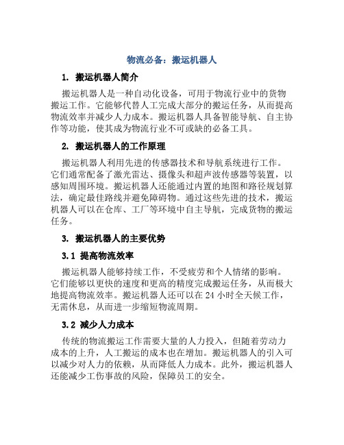
物流必备:搬运机器人1. 搬运机器人简介搬运机器人是一种自动化设备,可用于物流行业中的货物搬运工作。
它能够代替人工完成大部分的搬运任务,从而提高物流效率并减少人力成本。
搬运机器人具备智能导航、自主协作等功能,使其成为物流行业不可或缺的必备工具。
2. 搬运机器人的工作原理搬运机器人利用先进的传感器技术和导航系统进行工作。
它们通常配备了激光雷达、摄像头和超声波传感器等装置,以感知周围环境。
搬运机器人还能通过内置的地图和路径规划算法,确定最佳路线并避免障碍物。
通过这些先进的技术,搬运机器人可以在仓库、工厂等环境中自主导航,完成货物的搬运任务。
3. 搬运机器人的主要优势3.1 提高物流效率搬运机器人能够持续工作,不受疲劳和个人情绪的影响。
它们能够以更快的速度和更高的精度完成搬运任务,从而极大地提高物流效率。
搬运机器人还可以在24小时全天候工作,无需休息,从而进一步缩短物流周期。
3.2 减少人力成本传统的物流搬运工作需要大量的人力投入,但随着劳动力成本的上升,人工搬运的成本也在增加。
搬运机器人的引入可以减少对人力的依赖,从而降低人力成本。
此外,搬运机器人还能减少工伤事故的风险,保障员工的安全。
3.3 提升精度和准确性搬运机器人通过先进的传感器和导航系统,能够以更高的精度和准确性完成搬运任务。
它们能够准确识别货物并根据需要进行精确定位和操作,避免了人工搬运中可能出现的错误和损失,从而提高了物流的质量。
3.4 可自主协作搬运机器人可以通过网络进行通信和协作,实现多个机器人之间的合作工作。
它们能够互相协调行动,配合完成复杂的搬运任务。
这种自主协作的能力使得搬运机器人在处理大规模物流工作时更加高效,大大提升了物流行业的整体效益。
4. 使用搬运机器人的注意事项使用搬运机器人需要注意以下几点:4.1 安全隐患虽然搬运机器人能够降低工伤事故风险,但在使用过程中仍需注意安全。
确保机器人的传感器和导航系统正常工作,避免发生碰撞或者其他意外情况。
关于搬家机器人写作文资料
关于搬家机器人写作文资料
英文回答:
Moving robots are a great invention that has made the process of moving much easier. I remember when I had to move to a new apartment last year, and I had this amazing moving robot that helped me with all the heavy lifting. It was such a relief not to have to carry all those heavy
boxes up and down the stairs. The robot was able to
navigate through tight spaces and even carry multiple boxes at once. It saved me so much time and effort, and I was really grateful for it.
中文回答:
搬家机器人是一个伟大的发明,使搬家过程变得更加容易。
我
记得去年搬到新公寓的时候,我有一个了不起的搬家机器人,帮助
我搬运所有的重物。
不用自己抬着那些沉重的箱子上下楼真是太解
脱了。
这个机器人能够在狭窄空间中穿行,甚至一次搬运多个箱子。
它为我节省了大量的时间和精力,我真的为此感激不尽。
搬运机器人2021推选

够节省横向的工作空间
件〕和电磁吸盘。 1954年世界上首台AGV在美国的South Carolina州的Mercury Motor Freight公司的仓库内投入运营,用于实现出入库货物的自动搬运。
1、它能局部的代替人工操作;
传力机构形式较多,常 用的有:滑槽杠杆式、连 杆杠杆式、斜楔杠杆式、 齿轮齿条式、丝杠螺母式、 弹簧式和重力式。本次设
明确工件的结构形状和材料特性,定位精度要求,抓取、搬运时的受力特 性、尺寸和质量参数等,从而进一步确定对机械手结构及运行控制的 要求;
尽量选用定型的标准组件,简化设计制造过程,兼顾通用性和专用性,并 能实现柔性转换和编程控制。
搬运机器人的机械设计------各部件设计
搬运机器人由三局部组成 执行机构 驱动机构 控制机构
搬运机器人的意义
搬运机器人在实际的工作中就 是一个机械手,机械手的开展 是由于它的积极作用正日益为 人们所认识: 1、它能局部的代替人工操作; 2、它能按照生产工艺的要求,遵 循一定的程序、时间和位置来 完成工件的传送和装卸; 3、它能操作必要的机具进行焊接 和装配,从而大大的改善了工 人的劳动条件,显著的提高了 劳动生产率,加快实现工业生 产机械化和自动化的步伐。 因而,受到很多国家的重视, 投入大量的人力物力来研究和 应用。尤其是在高温、高压、 粉尘、噪音以及带有放射性器人的机械设计------手部设计
搬运拖车移动机器人中英文对照外文翻译文献

中英文资料外文翻译文献(文档含英文原文和中文翻译)一种实用的办法--带拖车移动机器人的反馈控制摘要本文提出了一种有效的方法来控制带拖车移动机器人。
轨迹跟踪和路径跟踪这两个问题已经得到解决。
接下来的问题是解决迭代轨迹跟踪。
并且把扰动考虑到路径跟踪内。
移动机器人Hilare的实验结果说明了我们方法的有效性。
1引言过去的8年,人们对非完整系统的运动控制做了大量的工作。
布洛基[2]提出了关于这种系统的一项具有挑战性的任务,配置的稳定性,证明它不能由一个简单的连续状态反馈。
作为替代办法随时间变化的反馈[10,4,11,13,14,15,18]或间断反馈[3]也随之被提出。
从[5]移动机器人的运动控制的一项调查可以看到。
另一方面,非完整系统的轨迹跟踪不符合布洛基的条件,从而使其这一个任务更为轻松。
许多著作也已经给出了移动机器人的特殊情况的这一问题[6,7,8,12,16]。
所有这些控制律都是工作在相同的假设下:系统的演变是完全已知和没有扰动使得系统偏离其轨迹。
很少有文章在处理移动机器人的控制时考虑到扰动的运动学方程。
但是[1]提出了一种有关稳定汽车的配置,有效的矢量控制扰动领域,并且建立在迭代轨迹跟踪的基础上。
存在的障碍使得达到规定路径的任务变得更加困难,因此在执行任务的任何动作之前都需要有一个路径规划。
在本文中,我们在迭代轨迹跟踪的基础上提出了一个健全的方案,使得带拖车的机器人按照规定路径行走。
该轨迹计算由规划的议案所描述[17],从而避免已经提交了输入的障碍物。
在下面,我们将不会给出任何有关规划的发展,我们提及这个参考的细节。
而且,我们认为,在某一特定轨迹的执行屈服于扰动。
我们选择的这些扰动模型是非常简单,非常一般。
它存在一些共同点[1]。
本文安排如下:第2节介绍我们的实验系统Hilare及其拖车:两个连接系统将被视为(图1)。
第3节处理控制方案及分析的稳定性和鲁棒性。
在第4节,我们介绍本实验结果。
图1带拖车的Hilare2 系统描述Hilare是一个有两个驱动轮的移动机器人。
工业搬运机器人的介绍,工业搬运机器人与生产转型间的关系
工业搬运机器人的介绍,工业搬运机器人与生产转型间的关系随着我国工业自动化逐渐发展成熟,工业搬运机器人得了很更进一步的应用,很多大企业工厂都开始使用工业机器人进行货物的搬运,它可以批量的完成工作,提高工作效率,下面就由易造机器人网的小编为大家详细的介绍一下工业搬运机器人。
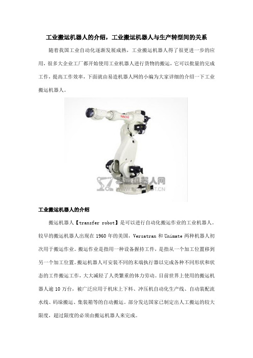
工业搬运机器人的介绍搬运机器人【transfer robot】是可以进行自动化搬运作业的工业机器人。
较早的搬运机器人出现在1960年的美国,Versatran和Unimate两种机器人初次用于搬运作业。
搬运作业是指用一种设备握持工件,是指从一个加工位置移到另一个加工位置。
搬运机器人可安装不同的末端执行器以完成各种不同形状和状态的工件搬运工作,大大减轻了人类繁重的体力劳动。
目前世界上使用的搬运机器人逾10万台,被广泛应用于机床上下料、冲压机自动化生产线、自动装配流水线、码垛搬运、集装箱等的自动搬运。
部分发达国家已制定出人工搬运的较大限度,超过限度的必须由搬运机器人来完成。
搬运机器人是近代自动控制领域出现的一项高新技术,涉及到了力学,机械学,电器液压气压技术,自动控制技术,传感器技术,单片机技术和计算机技术等学科领域,已成为现代机械制造生产体系中的一项重要组成部分。
它的优点是可以通过编程完成各种预期的任务,在自身结构和性能上有了人和机器的各自优势,尤其体现出了人工智能和适应性。
工业搬运机器人与生产转型间的关系众所周知,工业搬运机器人的自动化生产中占主要地位,国内市场需求也在行业转型的推动下迅速增长。
我国现在已是全球较大制造业国家,有世界工厂的称号,但是很大程度都是国内制造业当中大量的劳动密集型产业供献出来的。
对于我们而言,如今要想保持制造业主要国家地位,就需要开启产业升级模式,推动自动化发展。
这里就将进一步带动机器人行业市场发展。
中国正处于产业转型升级的关键时刻,越来越多的企业在生产制造过程中引入工业搬运机器人,它将深远影响中国制造的方方面面。
AGV搬运机器人

AGV搬运机器人简介AGV即:Automated Guided Vehicle 简称AGV,当前最常见的应用如:AGV搬运机器人或AGV 小车,主要功用集中在自动物流搬转运,AGV搬运机器人是通过特殊地标导航自动将物品运输至指定地点,最常见的引导方式为磁条引导,激光引导;目前最先进扩展性最强是由米克力美科技开发的超高频RFID引导。
磁条引导的方式是常用也是成本最低的方式,但是站点设置有一定的局限性以及对场地装修风格有一定影响;激光引导成本最高对场地要求也比较高所以一般不采用;RFID引导成本适中,其优点是引导精度高,站点设置更方便可满足最复杂的站点布局,对场所整体装修环境无影响,其次RFID高安全性稳定性也是磁条导航和激光导航方式不具备的。
引导方式:1.电磁感应式:也就是我们最常见的磁条导航,通过在地面黏贴磁性胶带,AGV自动搬运车经过时车底部装有电磁传感器会感应到地面磁条地标从而实现自动行驶运输货物,站点定义则依靠磁条极性的不同排列组合设置。
2.激光感应式:通过激光扫描器识别设置在其活动范围内的若干个定们标志来确定其坐标位置,从而引导AGV运行。
3.RFID感应式:通过RFID标签和读取装备自动检测坐标位置,实现AGV小车自动运行,站点定义通过芯片标签任意定义,即使最复杂的站点设置也能轻松完成。
优点:随着工厂自动化、计算机集成制造系统技术逐步发展、以及柔性制造系统、自动化立体仓库的广泛应用,AGV作为联系和调节离散型物流管理系统使其作业连续化的必要自动化搬运装卸手段,其应用范围和技术水平得到了迅猛的发展。
下面是AGV的优点介绍:1、自动化程度高——由计算机,电控设备,磁气感应SENSOR,激光反射板等控制。
当车间某一环节需要辅料时,由工作人员向计算机终端输入相关信息,计算机终端再将信息发送到中央控制室,由专业的技术人员向计算机发出指令,在电控设备的合作下,这一指令最终被AGV接受并执行——将辅料送至相应地点。
- 1、下载文档前请自行甄别文档内容的完整性,平台不提供额外的编辑、内容补充、找答案等附加服务。
- 2、"仅部分预览"的文档,不可在线预览部分如存在完整性等问题,可反馈申请退款(可完整预览的文档不适用该条件!)。
- 3、如文档侵犯您的权益,请联系客服反馈,我们会尽快为您处理(人工客服工作时间:9:00-18:30)。
外文翻译专业机械电子工程学生姓名张华班级 B机电092 学号 05指导教师袁健外文资料名称:Research,design andexperiment of end effectorfor wafer transfer robot外文资料出处:Industrail Robot:An International Journal 附件: 1.外文资料翻译译文2.外文原文晶片传送机器人末端效应器研究、设计和实验刘延杰、徐梦、曹玉梅张华译摘要:目的——晶片传送机器人扮演一个重要角色IC制造行业并且末端执行器是一个重要的组成部分的机器人。
本文的目的是使晶片传送机器人通过研究其末端执行器提高传输效率,同时减少晶片变形。
设计/方法/方法——有限元方法分析了晶片变形。
对于在真空晶片传送机器人工作,首先,作者运用来自壁虎的超细纤维阵列的设计灵感研究机器人的末端执行器,和现在之间方程机器人的交通加速度和参数的超细纤维数组。
基于这些研究,一种微阵列凹凸设计和应用到一个结构优化的末端执行器。
对于晶片传送机器人工作在大气环境中,作者分析了不同因素的影响晶片变形。
在吸收面积的压力分布的计算公式,提出了最大传输加速度。
最后, 根据这些研究得到了一个新的种末端执行器设计大气机器人。
结果——实验结果表明, 通过本文研究应用晶片传送机器人的转换效率已经得到显着提高。
并且晶片变形吸收力得到控制。
实际意义——通过实验可以看出,通过本文的研究,可以用来提高机器人传输能力, 在生产环境中减少晶片变形。
还为进一步改进和研究末端执行器打下坚实的基础,。
创意/价值——这是第一次应用研究由壁虎启发了的超细纤维阵列真空晶片传送机器人。
本文还通过有限元方法仔细分析不同因素在晶片变形的影响。
关键词:晶片传送机器人末端执行器、超细纤维数组、晶片1.介绍作为一个主要集成电路设备的制造行业,晶片机器人承担了精确定位,快速和稳定的传输晶片的任务。
随着集成电路产业的快速发展(比如晶圆的直径增加到300毫米), 机械制造技术的更高的要求是为了提高生产力,因此,更高的晶片传送效率是必要的。
同时,由于晶片变得越来越薄,因此晶片机器人的设计也要防止转移严重变形晶片。
末端执行器是晶圆转移机器人一个重要的组件,它有一个很大的影响传输效率机器人的硅片变形。
目前关于末端执行器的晶片传送机器人的研究很少。
因此,它是非常必要的相关研究。
发展至今有两种晶片传送机器人:真空晶片传送机器人和大气晶片传送机器人。
真空晶片传送机器人工作在真空环境而大气晶片传送机器人工作在大气环境。
对于真空晶片传送机器人,过境晶片依赖摩擦力晶片和晶圆自己的重量的末端执行器之间生成的。
虽然大气晶片传送机器人是使用真空泵在晶片和机器人的末端执行器之间产生真空。
在大气压力和真空中有一种压力区别,这造成了相当大的正常压力,然后生成足够的摩擦力来维持晶圆在机器人的位置。
2.研究对于大气晶片传送机器人对于晶片传送机器人工作在大气环境,晶片的两面的主要的压力差会使得摩擦力大到足以影响晶片。
晶片的自己的体重还有助于一代的摩擦力。
严重的晶片变形可能是由于大量吸收力,这是完全不可接受的。
因此,我们需要分析对晶片的变形产生影响各种因素。
考虑到高转换效率的要求,我们还应该建立最大转移加速和晶片传送机器人的末端执行器工作在大气环境的参数之间的关系。
(1)我们采用有限元分析方法分析吸收毛孔对晶片的变形数量的影响对于晶片的变形下产生不同数量的吸收毛孔。
这里我们假设吸收毛孔的半径3毫米均匀分布在一个圆半径为100毫米。
吸收毛孔的数量范围从三到无限的并且用于分析的晶片是直径300毫米厚度100微米。
分析结果显示在图1和表1。
结果表明,晶片的变形和应力减少增加吸收毛孔的数量,但在减少程度上变得越来越小。
考虑技术和经济可行性,我们最后选择四个吸收毛孔(图2)。
图1 包含4个或6个吸收毛孔约束的晶片的变形模拟图表1 仿真包含不同数量的吸收毛孔约束晶片的最大变形和应力图2 包含不同数量的吸收毛孔最大变形和应力曲线(2)吸收孔的位置也会影响的晶片变形。
通过同样的过程,我们分析晶片的变形和压力在行动与不同位置的吸收毛孔。
吸收孔隙分布圈的半径范围从30到150毫米。
分析结果显示在图3(a)。
根据这个结果,我们可以得到的R =110毫米是最佳吸收孔位置以防止晶片的变形(图4)。
图3 (a)包含不同位置的毛孔约束晶片的变形模拟图;(b)吸收面接触等效原理图图4 包含吸收毛孔的不同位置最大变形和应力曲线(3)半径影响吸收毛孔在晶片的变形作为吸收毛孔随其半径,吸收力它生成也会改变。
所以我们需要分析半径之间的关系的吸附孔,晶片变形。
结果显示在图5和表2。
图6显示晶片变形显着增加随着规模的毛孔吸收更大。
图5 不同的吸收孔隙半径的晶片变形的曲线表2 受到不同的半径吸收毛孔作用的最大的晶片变形接触宽度在晶片的变形接触宽度末端执行器之间的影响,晶片也会影响晶片应力和变形。
我们分析了晶片变形在不同接触宽度和结果如下所示(图6)。
结果表明,晶片变形和应力作为接触宽度的增加和减少的趋势线图7中所示。
当接触宽度是20毫米,晶片最大变形是约1微米,它是可接受的。
图6 不同接触宽度的晶片变形模拟图图7 不同接触宽度的最大变形和应力曲线(4)在吸收区域压力分布我们应该研究压力在吸收地区分布以防在晶圆上存在应力集中。
如图3所示(b),当晶片是作用下吸收力F,它相当于,晶片接触一个球是在推动,力F。
根据赫兹(1882)理论,当一个理想的球体接触一个平面,真正的接触面积可以拿到如下:F -吸收力;Rs -半径的球体,这里我们假定它等于半径的吸收毛孔;Rk . -半径的实际的接触面积,E,n -弹性模量和泊松晶圆片的比例;Es,vs -弹性模量和泊松比的球体,这里我们假设它们是材料相当的末端执行器。
如果某个地点之间的距离和中心的接触面积是r,然后上的压力这个特定的点是:总体压力接触面积是:对于典型的晶片和机器人工作在大气环境、材料参数是已知的。
Vs= ,Es = 68GPa,V=,E=的平均绩点。
我们把压力分布函数的接触面积显示在方程:图8显示,没有显着变化的压力值作为X1,X2的变化,这意味着压力是近均匀分布在整个吸收面积。
因此没有应力集中在吸收区域。
图8 吸收面积压力分布图3.设计对于真空晶片传送机器基于以上研究设计一种微阵列的肿块,我们尝试设计一种用于晶片传送微阵列凹凸。
为了降低晶片变形,我们选择四个肿块联系方式并且四个肿块是完全相同的。
从方便处理方面考虑,光刻胶苏8材料被用来制造了超细纤维数组并且采用光刻技术。
原理和实际图的微阵列肿块如图12所示。
超细纤维数组是均匀分布的面具,总面积5X5毫米。
这个面具是固定的上表面一个玻璃基片面积6X6毫米,厚度3毫米。
超细纤维数组、面具、玻璃衬底,三层组成的微阵列肿块。
材料参数和尺寸参数数组和薄片是超细纤维显示在表3。
表3 超细纤维数组和晶片材料参数和尺寸参数通过SEM照片我们可以看出,纤维的表面大约是一个圆形平面,所以真正的接触面积在防颤晶片和一个单纤维之间,面积接近πr2。
基于表V,这些已知值替换得到方程:当机器人采用这类超细纤维时最大传输加速度a= m /s2。
以直径300毫米并且厚度775毫米的晶圆的典型的转移为例。
晶圆片的重量公斤。
通过方程,当机器人采用这种超细纤维肿块时我们可以得到最大附着力是Fad= 。
它可以看到最大的附着力晶片和末端执行器之间太小,阻碍了释放晶片。
物理设计的末端执行器在集成电路产业晶片盒的半标准大小的规定为300毫米晶圆。
端效应的大小应该匹配晶圆框的大小,以正确工作。
因此,有一个请求端效应的大小是长度不超过450毫米,宽度不超过250毫米,厚度没有更多的超过5毫米。
基于请求,我们最后决定我们的结束效应是390毫米长,220毫米宽,4毫米厚度。
我们也优化了末端执行器的结构结合现有的样品,并想出了一个特殊的结构实现连接的凸起和微阵列末端执行器。
最后形成的末端执行器显示在图13。
末端执行器的振动将会导致严重的问题晶片传送。
这将导致末端执行器之间的摩擦和晶片盒、甚至碰撞,这将损害晶片。
也严重的振动将导致晶片脱离末端执行器并导致严重后果。
所以共振的结束效应器和机器人臂必须避免。
通过有限元素分析的末端执行器设计在本文,我们得到它的动态特性,如下所示表4。
表4 末端执行器设计的普通频率我们已经知道通过实验(不包括在这纸),机器人臂的振动频率是23赫兹,虽然第一阶固有频率的末端执行器是72赫兹,远远超过臂的振动频率。
输入的频率也低于1赫兹。
所以最后的效应器设计是本文能够避免共振与机器人的手臂,满足请求的动态特征。
对于大气晶片传送机器人在前面研究结果的基础上,我们设计四个吸收毛孔最后效应是一致的分布在一个圆半径为110毫米。
当前大气晶片传送机器人可以达到最大的传输加速度为1 g。
这里我们把目标的末端执行器的加速度设计在达到一个加速度的 g。
然后通过方程根据已知参数,半径吸收毛孔r可以计算为r=3毫米。
根据尺寸要求末端执行器和引用对现有产品,我们终于设计末端执行器的大气晶片传送机器人如图9所示。
它的接触宽度与晶片是20毫米。
图9 (a)大气晶片传送机器人末端执行器的前面原理图;(b)背面;(c)实物在案例的共振的末端执行器和机器人手臂,我们还必须分析末端执行器的动态特征。
他们见表5,从这可以看到,第一阶固有频率的结束效应是54302赫兹,比手臂的振动频率是23赫兹。
同样的频率输入低于1赫兹。
所以设计的末端执行器能够为了避免共振与机器人的手臂,来满足要求动态特性。
表5 大气机器人末端执行器的普通频率4.结论对于真空晶片传送机器人的末端执行器。
首先,本文应用研究壁虎启发超细纤维阵列的设计末端执行器的真空晶片传输机器人。
晶圆片的变形与不同的联系在真空条件转移比较它显示4个凹凸接触是最合适的方法。
超细纤维的研究数组用于晶片交通运输和关系在晶片传送加速度、附着力和材料、尺寸参数的超细纤维数组建立了。
然后一种微阵列凹凸与纤维直径5毫米和纤维长度15毫米的设计和固定到一个结构优化的末端执行器。
最后,实验结果表明,该机器人采用这种微阵列可以实现传输加速度撞s2,远远大于传统疙瘩由不锈钢吗钢或橡胶。
这意味着应用程序的超细纤维数组对真空转移机器人具有显着提高机器人的传输效率和这个有着重要的意义来集成电路制造行业。
还s2基本上是符合理论价值s2和它验证这项研究的正确性的超细纤维数组用于晶片过境。
对于末端执行器大气晶片传送机器人,我们已经分析了吸收毛孔的号码, 位置,半径和接触宽度在晶片变形影响。
据分析,四个吸收毛孔一致分布在一个圆半径为110 mm被选择作为我们的设计方案。
压力分布在吸收面积研究和结果显示没有压力集中在这个地区。
