赛弗粘滞阻尼器技术手册
Belimo FSNF24-S 失效保护阀说明书
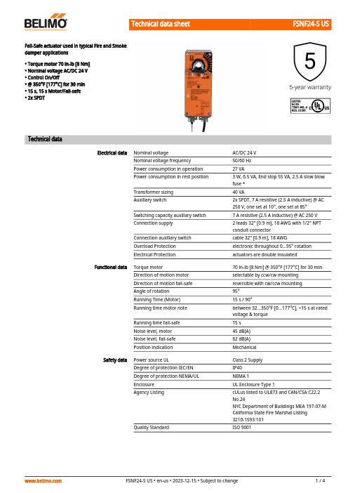
FSNF24-S USFail-Safe actuator used in typical Fire and Smokedamper applications• Torque motor 70 in-lb [8 Nm]• Nominal voltage AC/DC 24 V• Control On/Off• @ 350°F [177°C] for 30 min• 15 s, 15 s Motor/Fail-safe• 2x SPDTTechnical dataElectrical data Nominal voltage AC/DC 24 VNominal voltage frequency50/60 HzPower consumption in operation27 VAPower consumption in rest position 3 W, 6.5 VA, End stop 55 VA, 2.5 A slow blowfuse *Transformer sizing40 VAAuxiliary switch2x SPDT, 7 A resistive (2.5 A inductive) @ AC250 V, one set at 10°, one set at 85°Switching capacity auxiliary switch7 A resistive (2.5 A inductive) @ AC 250 VConnection supply 2 leads 32" [0.9 m], 18 AWG with 1/2" NPTconduit connectorConnection auxiliary switch cable 32" [0.9 m], 18 AWGOverload Protection electronic throughout 0...95° rotationElectrical Protection actuators are double insulatedFunctional data Torque motor70 in-lb [8 Nm] @ 350°F [177°C] for 30 minDirection of motion motor selectable by ccw/cw mountingDirection of motion fail-safe reversible with cw/ccw mountingAngle of rotation95°Running Time (Motor)15 s / 90°Running time motor note between 32...350°F [0...177°C], <15 s at ratedvoltage & torqueRunning time fail-safe15 sNoise level, motor45 dB(A)Noise level, fail-safe62 dB(A)Position indication MechanicalSafety data Power source UL Class 2 SupplyDegree of protection IEC/EN IP40Degree of protection NEMA/UL NEMA 1Enclosure UL Enclosure Type 1Agency Listing cULus listed to UL873 and CAN/CSA C22.2No.24NYC Department of Buildings MEA 197-07-MCalifornia State Fire Marshal Listing3210-1593:101Quality Standard ISO 9001Safety dataUL 2043 CompliantSuitable for use in air plenums per Section 300.22(C) of the NEC and Section 602 of the IMCAmbient humidity Max. 95% RH, non-condensing Ambient temperature 32...122°F [0...50°C ]Storage temperature -40...176°F [-40...80°C]Servicingmaintenance-free Weight Weight6.5 lb [3.0 kg]MaterialsHousing material galvanized steelGears steel, permanently lubricatedFootnotes† UL File XAPX.E108966•••Safety notes* Neither UL nor Belimo require local over-current protection. The FSNF actuators drawhigher peak current when driving against any type of stop. If used, this requires the value of a local fuse or breaker to be increased to avoid nuisance opening or tripping. A 2.5 A slow blow should be used for AC 24 V. A 0.5 A slow blow should be used for AC 120 V. A 0.25 A slow blow should be used for 230 V and a 0.3 A slow blow for AC 208 V. Transformers: Note that while a 24 V 100 VA transformer would handle 2 actuators, a 4 A breaker or plug fuse is insufficient. A 5 A slow blow would be required.Belimo Fire & Smoke actuators have passed the AMCA 520 and UL 555S Long Term Holding test. No special cycling is required during prolonged periods when actuator is driven open and held there. Periodic testing of dampers and actuators per local codes and NFPA 80 and NFPA 105 are required.The actuator contains no components which the user can replace or repair. A 1/2" threaded connector is standard. FSNFxx-FC models have a 3/8" Flex Connector. Other than the connector, these actuators are identical to the conduit connector version.Product featuresApplication The FS series of spring-return actuators are designed for the operation of UL555 and UL555S listed fire/smoke dampers in ventilation and air-conditioning systems.OperationThe actuator is mounted in its fail safe position with the damper blade(s) typically closed. Upon applying power, the actuator drives the damper to the open position. The internalspring is tensioned at the same time. If the power supply is interrupted, the spring moves the damper back to its fail-safe position.Typical specificationAll smoke and combination fire and smoke dampers shall be provided with Belimo FSTF, FSLF, FSNF, or FSAF series actuators. All substitutions must be approved before submission of bid. Damper and actuator shall have UL555S Listing for 250°F and/or 350°F. Actuator shall have been tested to UL2043 per requirements of IMC 602.2 and NEC 300.22 (c). Where position indication is required -S models with auxiliary switches shall be provided.AccessoriesElectrical accessoriesDescriptionType Thermoelectric tripping device, Duct inside temperature 165°F BAE165 US Auxiliary switch 2x SPDTS2A-F US Mechanical accessoriesDescriptionType Anti-rotation bracket, for AF / NF AF-P End stop indicator for AF / NFIND-AF2DescriptionType Shaft clamp for AF..K4-1 US Actuator arm, clamping range ø10...20 mmKH-AFKH-AF-1 US SH8Angle of rotation limiter for Classic AF/NF.ZDB-AF2 US Mounting bracket for AF..ZG-100Mounting bracket for AF / NFZG-101Crank arm adapter kit Incl. mounting hardwareZG-AF US ZG-AF108Damper clip for damper blade, 3.5” width.ZG-DC1ZG-DC2Weather shield 13x8x6" [330x203x152 mm] (LxWxH)ZS-100Weather shield 406x213x102 mm [16x8-3/8x4"] (LxWxH)ZS-150Explosion proof housing 16x10x6.435" [406x254x164 mm] (LxWxH), UL and CSA, Class I, Zone 1&2, Groups B, C, D, (NEMA 7), Class III, Hazardous (classified) LocationsZS-260Weather shield 17-1/4x8-3/4x5-1/2" [438x222x140 mm] (LxWxH), NEMA 4X, with mounting bracketsZS-300Electrical installationINSTALLATION NOTESProvide overload protection and disconnect as required.Actuators may be powered in parallel. Power consumption must be observed.S4 makes to S6 when actuator is powered open.Auxiliary switches are for end position indication or interlock control.Double insulated.Ground present on some models.Meets cULus requirements without the need of an electrical ground connection.Parallel Actuator Wiring Wiring diagramsAC/DC 24 VFSNF24-S US Wiring diagramsTypical containment damper control wiringParallel Actuator WiringAuxiliary SwitchElectrical installationDimensions。
shafer 操作维护手册

本流程图具有如下操作功能: a) 电子式爆管保护功能(关阀)
在电子控制单元(20)中,带有压力传感器,通过管路与天然气主管线连接以获 得压力信号。 当管线中的实际压力数据达到并超过电子控制单元中设定的三种压力参 数中的任何一种时(高压关阀,低压关阀,压降速率关阀),并且此事件持续时间达到 电子控制单元中设定的延时时间后,电子控制单元中的正常处于关闭状态的电磁阀通 电,并使气流流向正常处于关闭状态的先导阀(18)。 由于“梭阀”模块(11,14, 16)的信号与动力的比是 33 比 1, 这样先导阀(18)打开后,“梭阀”打开,容许动 力气体从动力接口到气缸中活塞接口(14),动力“梭子”(16)被打开,容许动力气 流进入原来被气缸封闭住的空间,从而进入执行器关闭阀门的气/液联动罐(3),气流 将进一步通过手动泵(4)和速度调节装置(5),从而进入旋转叶片执行器的本体,执 行器在这个动力驱使下,运动直至关闭阀门。当电子控制单元(20)中预先设定的电 磁阀“待命”时间(10-255 秒)完成时,此时电磁阀断电。 当先导阀关闭时,引导气 从“梭阀“模块(14)的孔板处排出,位于“梭阀”模块中负责关闭阀门功能的那一 侧梭子关闭,致使负责关闭阀门的气/液联动罐(3)压力降低减压。 当气/液联动罐 (3)压力降低全部完成,整个气/液联动系统重新回到初始的平衡状态。
c) 就地手动泵开/关阀门和执行器 无论想开或关阀,最简单的就是用一个手柄装在执行器控制箱内的手动泵(4)的
接口上,使用这个手柄上下压动,将力推向泵的中部。(注:泵的标记将指明开或关阀 的动作方向。)
使用供货时提供的手动泵手柄,向上抬举这个手柄时,手动泵的插销提起,使得 液压油进入手动泵,再向下推压手柄,给液压油加压,使得液压油进入执行器。重复 上抬、下压手柄的动作,直至开或关阀的过程全部完成。泵被泄压并回到初始状态, 此时任何自动控制这个执行器的功能可以被使用。 1.1.2.2 越站干线使用的气液联动执行机构
粘滞阻尼器产品手册
粘滞阻尼器产品手册一、产品概述粘滞阻尼器是一种高分子材料制成的阻尼器,具有优良的阻尼性能和稳定的力学性能。
它通过利用高分子材料的粘性和弹性,在振动过程中产生阻尼效应,有效地吸收和消耗振动能量,达到减振降噪的目的。
该产品广泛应用于桥梁、建筑、机械等领域,对于提高结构安全性、减缓振动和噪音具有重要作用。
二、设计与制造1. 设计:在设计粘滞阻尼器时,需要根据使用场合和要求,选择合适的高分子材料和制造工艺,确定阻尼器的形状和尺寸。
同时,需要进行严格的力学分析和计算,确保阻尼器在承受载荷和使用过程中具有稳定的性能。
2. 制造:粘滞阻尼器的制造过程包括配料、成型、硫化等环节。
制造过程中需要严格控制材料配方、工艺参数和加工精度,确保产品质量。
三、安装与调试1. 安装:根据使用要求,选择合适的安装位置和方式。
一般采用螺栓或焊接方式将阻尼器固定在结构上。
安装过程中需要注意保证阻尼器不受损坏,并确保连接牢固可靠。
2. 调试:在安装完成后,需要对粘滞阻尼器进行调试,以确保其正常工作。
调试过程中可以通过调整阻尼器的刚度和阻尼系数,以达到最佳的减振效果。
四、使用与维护1. 使用:在使用粘滞阻尼器时,需要注意避免超载和过载情况的发生,以保证阻尼器的正常使用。
同时,需要定期检查阻尼器的外观和连接部位,确保其完好无损。
2. 维护:为了保证粘滞阻尼器的长期稳定性和延长其使用寿命,需要定期进行维护保养。
具体包括清除表面污垢和杂质,保持阻尼器内部清洁等。
五、性能测试与评估1. 性能测试:为了评估粘滞阻尼器的性能,需要进行一系列的测试。
包括阻尼器的刚度测试、阻尼系数测试、耐久性测试等。
通过这些测试可以全面了解阻尼器的性能指标和技术参数。
2. 性能评估:根据测试结果,可以对粘滞阻尼器的性能进行评估。
评估内容包括比较不同产品之间的性能差异、分析使用过程中性能的变化情况等。
这有助于用户选择合适的产品,并采取相应的措施来提高结构的减振效果。
六、故障诊断与排除1. 故障诊断:在使用过程中,如果粘滞阻尼器出现故障或异常情况,需要进行及时的诊断。
R17K.2E中文使用说明书

R17K.2E调速型液力偶合器使用说明书安全手则注意当装置运行时,可能会在设备、组件,以及管线上产生造成危险的电压及/或高压和高温。
在本装置与设备以及管线的内部,除其他零部件外,含有作为运行介质的油。
因此,如果处理不当,可能会伤害人员或损坏财产。
如果对油及润滑剂不恰当处理会对环境造成污染。
必须由合格人员从事对油的灌注、更换、处理、以及废物处置的工作。
重要事项只有合格人员才允许对该装置、该设备及其介质进行操作。
按照指导说明妥善地运输、贮存、安装调试,妥善地搬运、合理地使用操作介质油,并且,小心地进行操作与维修。
如果需要更详细的资料,或者有任何问题未能按操作手册解决,请于VOITH公司的下属公司或工厂直接联系。
合格人员合格人员是指:对该产品的运输、贮存、装配、安装、调试、操作以及维修保养等熟悉的人员,例如:-能根据对于电路/接线、高压与高温以及对环境有害或不利的介质等方面建立的安全实践情况;接受培训、指导,并且被授权对装置、设备与系统进行操作与维修。
-能够适当处理与废弃一些介质及其组件,例如:过滤器、单向系统或工作油等。
-根据对于设备维修保养以及安全使用方面已建立的安全实践情况,接受培训或指导。
-接受急救培训。
安全手则附页在起动前,有关VOITH公司的一切指示(参阅操作手册)须完全遵守。
在起动前,所有转动部件必须有防护罩作保护。
无论在何种情况下,在移动外壳前,必须清楚所有电器设备如主马达、起动泵马达、执行器均不在操作状态中。
安装或解体应按VOITH公司的指示由合格的技术人员处理。
在操作过程中,VOITH公司的液力偶合器不应打开。
在操作时,外壳表面温度可能上升至摄氏80度。
如操作人员长时间站在运转中的偶合器侧而不佩带耳塞,噪声可能影响其听觉。
最高噪声水平:参见数据资料。
上述所列只包括厂方已知的典型及无法避免的意外风险,不能作索赔用。
装配与解体的安装运行 (1)1一般说明 (1)2油循环 (1)2.1工作油循环 (1)2.2润滑油循环 (2)2.3外部供油 (2)3勺管调节 (2)3.1勺管定位 (2)4交付状态条件 (3)5工作油 (4)5.1偶合器注油 (4)6调试 (4)6.1试运行准备 (5)6.2试车 (6)6.3停机和备用状态下所需措施 (6)7液力偶合器的操作运行 (7)7.1偶合器的起动、运行、停机及切断设备电源时采取的措施 (7)7.2润滑油压、润滑油压监测 (8)7.3工作油监测 (9)7.4轴承温度 (9)7.5润滑油滤网 (9)7.6油位指示 (9)8偶合器的维护 (10)8.1双筒滤网的维护 (10)8.2设备运行时的维护 (13)8.3设备停机时的维护 (13)9偶合器的大修 (14)9.1概述 (14)9.2必要条件 (14)9.3解体与再装配 (14)10偶合器的解体与重新组装 (16)10.1概述 (16)10.2清洗和检查偶合器部件 (19)10.3重新组装 (20)10.4其它工作 (23)技术参数 (24)故障排除表 (25)用于“R”型VOITH液力偶合器的运行液 (29)“R”,“S”,“T”,“TP”型液力偶合器,“VHBI”制动闸和“E”转矩转换器的保护和包装规范 (31)液力偶合器上的消声罩安装 (33)换油标准 (34)油的含水量 (35)附录1轴承间隙 (38)附录4轴的偏移 (39)附录5冷油器布置、冷却水温度调节装置控制和油温控制 (40)附录6压力开关的顺序转换和线路图 (48)附录7油循环及测点布置 (50)附录9测量仪表 (55)附录10勺管和控制轴安装说明 (58) (58) (58)附录12安装说明 (59)1概述 (59)2混凝土基础上的安装准备 (60)2.1基础检查 (60)2.2对准用调整垫片 (60)2.3安装联轴器 (60)2.4安装基础轨道和排油管 (61)3液力偶合器在混凝土基础上的定位 (62)4对中调整精度 (63)5对中心 (64)5.1基础地脚螺栓灌浆初步对中 (64)5.2无接长滑套的联轴器的初步对中 (65)5.3带有中间体或接长滑套联轴器的初步对中 (67)5.4地脚螺栓灌浆 (68)5.5地脚螺栓两侧垫片的定位 (69)5.6最终对中心 (70)5.7今后泵组对中心 (71)6现场管路、冷却器布置和冷却器通风 (73)7供给各机器的润滑油 (74)8防护罩 (74)9安装后的防护保存 (75)10电气安装 (75)装配与解体的安装运行1一般说明液力偶合器用来对高速的工业机器进行无级调速控制,偶合器的主体部分与增速齿轮合并在同一个箱体中,箱体的下部作为油箱。
粘滞阻尼器参数设置要点
粘滞阻尼器参数设置要点1. 引言1.1 什么是粘滞阻尼器粘滞阻尼器是一种通过粘滞材料制成的结构抑制振动和减小结构响应的装置。
其原理是利用粘滞材料的能量耗散和变形来吸收结构振动产生的能量,从而减小结构的振动幅值和响应。
粘滞阻尼器通常由粘滞材料、支撑结构和固定装置组成,通过将粘滞材料固定在结构中,使其在结构振动时发生相对位移和形变,从而实现能量的耗散和减振效果。
粘滞阻尼器具有体积小、重量轻、安装方便等优点,广泛应用于桥梁、建筑、风电、交通运输等工程领域。
在地震和风灾等自然灾害频发的地区,粘滞阻尼器更能有效提高结构的抗震和防风性能,减少灾害损失。
粘滞阻尼器是一种重要的结构减震控制装置,对结构安全性和稳定性具有重要作用,是当前结构工程领域值得研究和推广的一个方向。
1.2 粘滞阻尼器在工程中的作用粘滞阻尼器在工程中的作用非常重要,它可以有效地降低结构在地震或风灾等外部力作用下的振动响应,提高结构的稳定性和安全性。
粘滞阻尼器可以吸收和耗散结构振动的能量,减小结构的位移和加速度响应,从而降低结构受到的损害。
在工程实践中,粘滞阻尼器被广泛应用于桥梁、高层建筑、烟囱、风力发电塔等结构中,通过合理设置参数来实现结构的防震和减震效果。
粘滞阻尼器与传统的结构减震方法相比,具有结构简单、安装方便、成本低廉等优势,因此在工程中得到了广泛应用。
通过科学合理地设置粘滞阻尼器的参数,可以进一步提高结构的抗震性能,降低结构的振动响应,保障结构和人员的安全。
了解粘滞阻尼器在工程中的作用,掌握粘滞阻尼器参数设置的要点是非常重要的,可以帮助工程师更好地设计和应用粘滞阻尼器,提高结构的整体性能和安全性。
2. 正文2.1 粘滞阻尼器参数设置的重要性粘滞阻尼器参数设置的重要性在工程中起着至关重要的作用。
粘滞阻尼器是一种通过黏滞力和阻尼力来消耗结构振动能量并减小结构响应的装置,在地震、风荷载等外部作用下能有效减小结构变形和位移,提高结构的稳定性和抗震性能。
KVFC407EB说明书

KVFC407EB说明书1打开面板上的控制器按钮,控制器得电,控制器开始自检,等控制器自检完毕后,进入主菜单。
2按ENTER键进入Controller菜单中,选中Fdback按ENTER键为AC1 Cond,然后按HOME键返回主菜单。
表示为位移控制模式。
3进入Limit Setting,选DC2UP,设定限位保护的峰值,选DC2LO,设定限位保护的谷值。
表示为力保护。
4设定完毕后,在控制器的面板上打Hydraulic Pressure的“low”,然后在面板上按电机1,即为低压启动。
再打开主菜单中的Function Generator,把SPAN设置为0,设置setpiont的值,然后按ENTER键,活塞就会到达指定的位置。
5做实验前,先推一下负荷传感器,看DC2COND的变化,DC2COND假设为负向增加(从-2变为-3),则方向正确。
6在Controller菜单中,将PGain设为2.0000VV,再将Fdback改为DC2COND。
7设置完毕后,在Limit Setting菜单中设置DC2UP,DC2LOW力保护。
8在Function Generator中设置Setpiont起始点的力,Span设为0。
9然后在控制器的面板上打Hydraulic Pressure的“low”,然后在面板上按电机l,即为低压启动。
然后打Hydraulic Pressure的“HIGH”,即为高压运行,活塞就会移动去寻找设定的那个力。
当活塞压到试样时,按控制器面板上的按钮,显示反馈过来的力。
10最后在Function Generator菜单中设置起始点Setpoint的数值,然后算出振幅,在Span中设定振幅,在Freq设定频率,在Preset设置预定实验次数,设定完毕,在控制器面板上的Program Contro1位置按“Run”,就开始做实验。
粘滞阻尼器论文ppt
7
Harbin Institute of Technology
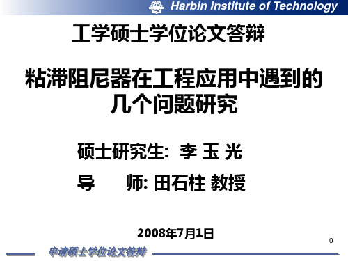
1.7 孔隙式粘滞阻尼器构造
泰勒公司生产单出杆
国产某型号双出杆
单出杆 1—油缸壁 2—油腔 3—阻尼孔 4—活塞
双出杆 5—活塞杆
8
申请硕士学位论文答辩
Harbin Institute of Technology
1.8 本文研究主要内容
表3-7 G试验工况 试验工况
工况 f(Hz) G1 0.1 G2 0.2 20 G3 0.2 30 G4 0.2 40 G5 0.2 60 G6 0.3 10 G7 0.4 10 G8 0.4 20 G9 0.4 30 G10 0.5 30 G11 0.6 20 G12 1 15 G13 1.5 10
18
申请硕士学位论文答辩
Harbin Institute of Technology
表3-5 E试验工况 试验工况
工况 f (Hz) A(mm) E1 0.1 10 E2 0.1 40. E3 0.1 50 E4 0.15 30 E5 0.2 10 E6 0.2 25 E7 0.3 10 E8 0.4 10 E9 0.5 8 E10 0.5 10
13
申请硕士学位论文答辩
Harbin Institute of Technology
3.2 阻尼器的连接
本次试验的阻尼器进行了改进: 本次试验的阻尼器进行了改进:以往做试验时阻 尼器端部用销轴与作动器连接, 尼器端部用销轴与作动器连接,销轴与耳环之间缝隙 影响位移的测定,本次试验阻尼器的端部为矩形, 影响位移的测定,本次试验阻尼器的端部为矩形,这 样作动器夹具可以直接夹住,不用销轴, 样作动器夹具可以直接夹住,不用销轴,这样可以减 小位移误差。 小位移误差。
AVENTICS CON-CB 联桥控制器说明书
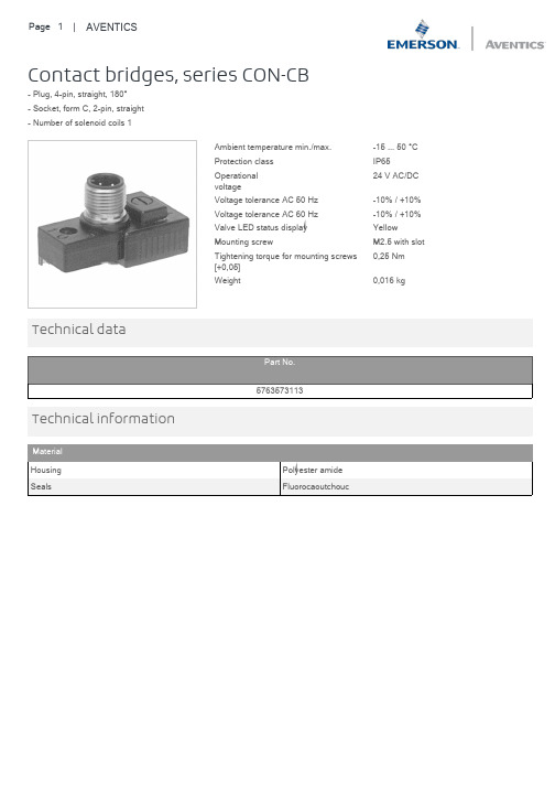
Contact bridges, series CON-CB- Plug, 4-pin, straight, 180°- Socket, form C, 2-pin, straight- Number of solenoid coils 1Ambient temperature min./max.-15 ... 50 °CProtection class IP6524 V AC/DCOperationalvoltageVoltage tolerance AC 50 Hz-10% / +10%Voltage tolerance AC 60 Hz-10% / +10%Valve LED status display YellowMounting screw M2.5 with slot0,25 NmTightening torque for mounting screws[+0,05]Weight0,016 kg Technical dataTechnical informationMaterial1) not assigned2) not assigned3) 0 V4) magnet 145) Sealing cap for manual override not removable6) Removable7) LED valve8) captive seal and screwPDF creation date:01.12.2020Your local contact:/contactus/EmersonAutomationSolutions/company/Emerson-Automation-SolutionsAn example configuration is depicted on the title page. The delivered product may thus vary from that in the illustration. Subject to change. This Document, as well as the data, specifications and other information set forth in it, are the exclusive property of AVENTICS GmbH. It may not be reproduced or given to third parties without its consent. Only use the AVENTICS products shown in industrial applications. Read the product documentation completely and carefully before using the product. Observe the applicable regulations and laws of the respective country. When integrating the product into applications, note the system manufacturer's specifications for safe use of the product. The data specified only serve to describe the product. No statements concerning a certain condition or suitability for a certain application can be derived from our information.The information given does not release the user from the obligation of own judgement and verification. It must be remembered that the products aresubject to a natural process of wear and aging.of the Emerson family of companies. All other marks are the property of their respective owners. © 2020 Emerson Electric Co.All rights reserved.2020-12。
KNF Woulfe 泵辅助器件说明书
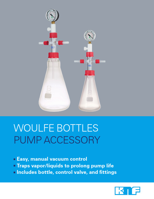
■■■PUMP ACCESSORYWOULFE BOTTLESRev: 04/2016KNF Neuberger Inc. ■ 2 Black Forest Rd, Trenton, NJ 08691 ■ 609-890-8600 ■ **************■ DESCRIPTIONThe KNF Woulfe bottle is a combination vacuum regulator and trap. Offered in two sizes — 500 and 1,000 mL — these safety-coated bottles include a ventilation (bleed) valve for vacuum control and fittings for 3/8" ID tubing connections.APPLICATIONS■ Vacuum control – Manually control vacuum performance to match specific applicationrequirements with a KNF Woulfe bottle. Vacuum regulation is particularly useful when a pump’s flow and/or end vacuum is too high for certain applications, or when control over vacuum level is important to the success or speed of an operation.Place a KNF Woulfe bottle between your laboratory device and KNF vacuum pump to control systempressure with the ventilation valve. Now your pump can be used in a wider variety of applications!The most typical application for a KNF Woulfe bottle is rotary evaporation, where regulation is necessary to optimize evaporation rates. Other applications include aspiration, degassing, and filtration.■Vacuum trap – Use a KNF Woulfe bottle in applications where wet vapors and/or small amounts of liquids are transferred in a vacuum system. Place the bottle inline between laboratory device and vacuum pump to capture potentially damaging liquid, thus extending the life of your pump.SPECIFICATIONS■ Thick-walled Erlenmeyer flask with plastic safety coating■ Vacuum gauge with two scales (1000 – 0 mbar, 760 – 0 mm Hg)■ PVC ventilation valve for vacuum regulation■ Glass port thread: GL-18 with plastic fittings for 3/8" ID tubing■ GL-45 threaded bottle neck■■ ■KNF Woulfe bottles are ideal for use with LABOPORT ®pumps.LABOPORT ® is a registered trademark of KNF Neuberger GmbH。
粘滞阻尼器技术
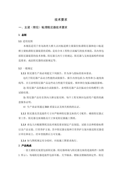
技术要求一、主梁(限位)粘滞阻尼器技术要求1. 总则1.1 适用范围本规范适用于青岛海湾大桥大沽河航道桥主梁限位粘滞阻尼器和沧口航道桥主梁粘滞阻尼器装置的采购,是结合本工程特点而编写的技术规范。
其内容包括阻尼器装置的技术参数,阻尼器几何尺寸的规定,阻尼器与支座连接构件的制造要求,成品阻尼器的试验规定等。
1.2 一般规定1.2.1 阻尼器生产商必须提交下列报告,作为参与投标的基本要求。
1)关于阻尼器产品动力性能的试验报告。
报告内容包括力-变形和力-速度曲线等,并且表明阻尼器产品这些动力性能不受温度、频率和往复振动幅值影响。
2) 阻尼器产品的振动台试验报告。
表明阻尼器产品在振动台结构模型上的试验结果。
3) 阻尼器产品有在国内大桥安装实例。
每个工程实例应包括用户提供的满意服务证明。
4)生产商必须通过ISO质量认证及相关机构的认证。
1.2.2 阻尼器及其连接件尺寸应严格和阻尼器支座的尺寸配作,确保阻尼器正常工作。
阻尼器支座规格及尺寸参见阻尼器施工图纸。
1.2.3承包人应根据图纸及技术规范要求制定产品制造、试验方法和检验标准以及产品安装、日常养护方案。
其中阻尼器安装和日常养护方案应报送阻尼器设计单位和业主,经审查批准后方可实施。
1.2.4如与图纸规定有分歧时,应按施工图要求执行。
2. 产品构成一套主梁阻尼装置包括阻尼器、阻尼器两端与阻尼器支座的连接构件(如图1所示),每端阻尼器连接件包括耳板、关节轴承、销轴及销轴的固定件。
阻尼器支座以及阻尼器支座与结构的连接构造由承包人预先制作安装。
图 1. 阻尼器产品构成2.1阻尼器连接件包括耳板和销轴,必须和阻尼器及支座配作,以满足其装配要求。
2.2阻尼器能够在横向进行不小于5度的偏移,以满足桥梁横向的偏移误差。
2.3阻尼器产品必须可以进行温度补偿,以保证阻尼器工作时内部工作压力保持恒定。
3. 阻尼器技术参数3.1.1粘滞阻尼器沧口航道桥采用的粘滞阻尼器是一种用于安装在发生相对位移的桥梁构件之间,在缓慢施加的静态荷载,如温度、汽车荷载等作用下可自由变形,在快速作用的动态荷载,如汽车振动、地震、脉动风等作用下,产生阻尼力并耗散能量的振动控制装置。
VWD-XF-SMY26EN 轻型迷你2口堵阀操作手册说明书
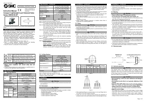
Warning
• To prevent uncontrolled tube movement, install protective covers or fasten tubes securely in place.
• If using tube piping, secure the product to a permanent fixture. Do not suspend it by the tubing.
is compatible with SMC fittings (KQ2 series).
Note 3) When using One-touch fittings with water, care must be taken
when handling tubing and piping conditions to prevent water
• Refer to product catalogue, Operation Manual and Handling Precautions for SMC Products for additional information.
• Keep this manual in a safe place for future reference.
VDW30 VDW40
100 g 230 g
Body material
PPS
Seal material
NBR, FKM, EPDM
Table 1.
Note 1) Products with power-saving circuit only.
Note 2) When using One-touch fittings, make sure to employ tubing that
2010.01.20 阻尼板使用说明
2 自粘型沥青阻尼板
1. 技术性能 1.1 密度: 2900±200g/m2。 1.2 灰分:(50±5)%。 1.3 拉断力:N ≥50。 1.4 弯曲刚度:400角弯曲不断裂. 1.5 气味:≤2.5 1.6总碳排放:µgc/g ≤50 1.7可凝结成份:mg≤3 1.8 雾度值:%≥60 1.9剥离强度:N≥25 1.10防腐蚀性:480h盐雾 不得迁移 1.11耐低温性:-40℃/24h 230mm落球冲 击不脱落 1.12耐热性能:110℃/24h 不得溶解、脱落 和起泡。 1.13阻尼系数(见左图)
损耗因子与频率关系消除噪声的手段利用先进的进口设备进行不同材料的阻尼分析不同产品阻尼系数对比图00200400600801012014016018020220240260280303203403603804042203040506070温度普通阻尼板一般阻尼板发泡型阻尼板树脂约束型阻尼板消除噪声的手段利用先进的仿真手段进行车体模态分析8通道数据采集前端消除噪声的手段利用先进的测试手段进行车体不同部位的噪声频谱分析8通道数据采集前端消除噪声的手段根据不同分析数据建立数据库根据不同的部位噪声的频率我们设计出不同类型的产品阻尼板类asphaltdampingpad热熔型沥青阻尼板自粘型沥青阻尼板磁性沥青阻尼板约束型沥青阻尼板发泡型沥青阻尼板毛毡型阻尼板结构密封胶类sealertape乳胶型发泡密封胶抗石击密封胶点焊胶膨胀型pvc涂料pvcrpp油箱用密封胶车身焊缝胶高发泡立柱填充环氧加强板特种油性胶丁基橡胶防振垫丁基胶带消除噪声的手段约束型沥青阻尼板在汽车上应用前地板位置温度高振动大车在行走过程地板会产生扭变采用树脂约束层阻尼板可以克服扭变产生起到减少振动及噪音的效果
阻尼板装车情况
• 此处添加图片 • 环氧加强板:此 类型产品通常在焊 装车间装配,主要 作用增加车身局部 钢板强度。
Parker Hannifin 三角式管缝纠缠装置说明书

Parker Hannifin CorporationTube Fittings Division 3885 Gateway Blvd.Columbus, OH 43228 USAPhone: (614) 279-7070 • Fax: (614) /tfdBulletin No. 4290-KF, 11/04The World StandardNew, from Parker’s Tube Fitting Division, the KarryFlare!The KarryFlare is a newly designed, portable flaring device for fabricating 37° tube flares. It’s lightweight,portable, and great for on-site flaring of large diameter steel and stainless steel tubing (¼ inch through 1½inches and 6mm to 38mm). The KarryFlare’s telescopic handle and wheeled carrying case makes it ideal for transporting from work site to work site.The KarryFlare flaring unit consists of a hydraulic flaring device and a hand-operated hydraulic, pump conveniently assembled on a portable steel carrying frame. Flare size and dimension are controlled manually by a pressure gauge and simple to use tube flaringreference chart. Reliable, simple to operate, and easy to transport!Technical Data•37° flaring for ISO 8434-2 / SAE J514 flared fittings •Flare capabilities of ¼" – 1½" and 6mm – 38mm•Maximum wall thickness of 1½" x 0.120" and 38mm x 4mm•Weight: approximately 62 lbs.•Dimensions: L 30" x W 14" x H 10"•For fitting assembly see Triple-Lok assembly instructions•Unit supplied with a 37° cone and uses the same dies as the discontinued 1015-1 flaring machine Advantages•Portable for on-site tube flaring •Easy to operate•Small tooling and setup time required •Localized, manual power supply•Robust, lightweight metal case with telescopic handle •Repeatable and consistent resultsApplications•Assembly of 37° flared fittings in low quantities•On site repair of mobile, agricultural, and construction equipment•R&D, repair, and plant maintenance workshops Part Number:KarryFlareKarryFlare - 37° Flaring Components and Capabilities。
Fredenstein F607监控控制器操作手册说明书
F607 Monitor ControllerOperating ManualThe F607 is a high performance professional monitor controller, offering an effective monitor volume control for project and home studios out of a Fredenstein Bento rack. The F607 features a second unbalanced stereo input as well as mute, dim, mono and balance control functions.If used in a Bento D rack with, all parameters can be monitored on the LCD display.As all Fredenstein products, the F607 is designed by a German-American team and manufactured in Taiwan.Overview:Rotary Controls:Volume:V olume controlSwitches:AUX :Selects unbalanced AUX InputMONO:Mono ModeMUTE: Speakers muting (speakers off)DIM:Sets reduced V olume (programmable)CAL Main:Calibration modes for MAIN (balanced) inputCAL AUX:Calibration modes for AUX (unbalanced) inputConnector:AUX INPUT:Unbalanced Stereo AUX input (TRS)Installation:Please power down your rack or box first before inserting the F607. The power requirements are +/-16V, +/-100mA. Please connect the left channel of your speaker amp or your left active monitor to the MAIN out XLR and the right channel to the AUX out XLR located on the backpanel of your Fredenstein Bento rack. Please be aware, the F607 will not work in any third party enclosures. In case you are using a Fredenstein Bento D rack, you can calibrate the system, please apply your reference level to the F607 and set the volume to 78 dBA on the Bento D display. Then adjust the sensitivity of your speaker amp(s) or active monitors to a sound pressure level of 78 dBA at your listening position with the help of a sound pressure meter.Volume:V olume control 20 dBA to 115 dbA (when calibrated)AUX:Selects the AUX TRS unbalanced Stereo input located on the front panel, if not activated the MAIN XLR balanced inputs of the Fredenstein Bento rack are selected, the left channels is the XLR Main input, the right channel the XLR AUX input on the rear panel of the Bento rack.Mono:Mono mode, the signals for left and right channels are added and fed two both speakers.Mute:Mute control, if activated, no signal is delivered to the speakers.DIM:The DIM control selects a lower volume, default is -20dB, but the user can set the DIM depth to any value between -40 dB and 0 dBCAL MAIN:Calibration on main input balance, if both CAL MAIN and DIM active, calibration of DIM DEPTH, in both cases the parameters are altered by using the volume control.If the CAL MAIN button is pressed for about 3 seconds the function turns off and all calibration parameters are set to the default values.CAL AUX:Calibration on AUX input balance, if both CAL AUX and DIM active, calibration of AUX volume to ensure the same volume of MAIN inputs and AUX inputs. The gain range is – 20dB to + 20 dB in both cases the parameters are altered by using the volume control.If the AUX MAIN button is pressed for about 3 seconds the function turns off and all AUX parameters, AUX BALANCE and AUX TRIM, are set to the default values.All parameters are internally stored in a non-volatile memory and are automatically recalled at power-up. The F607 is powered by a 32bit ARM CPU.Technical Data:Frequency Response: 10 Hz – 30,000 Hz, +/- 0.5dB Distortion:< 0.01%SNR:> 100 dBInput Impedance:> 40 KOhmMax. Input Level:+ 24dBuOutput Impedance:200 Ohms (recommended load > 1.2KOhm) Max. Output Level:+ 24 dBuContact Info:Fredenstein Professional Audio by Orion Communication7F-1, No. 582, Ruei Guang Rd.Neihu DistrictTaipei 114TaiwanPhone: + 886-2-2657-2618 Email:******************** Web: 。
Curt 18050 调节式接收者牵绊说明书
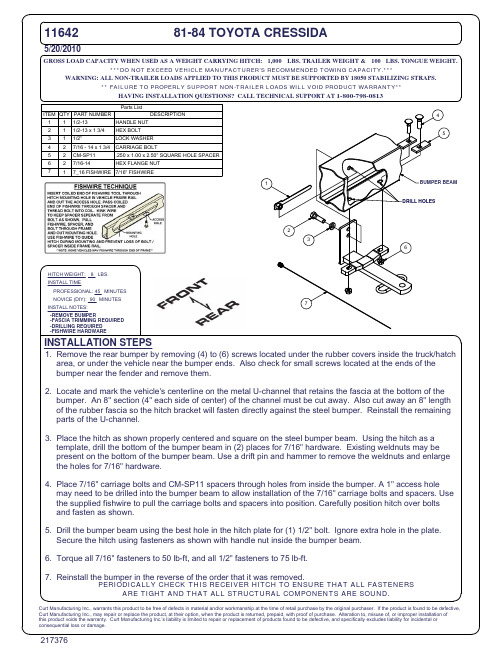
Curt Manufacturing Inc., warrants this product to be free of defects in material and/or workmanship at the time of retail purchase by the original purchaser. If the product is found to be defective, Curt Manufacturing Inc., may repair or replace the product, at their option, when the product is returned, prepaid, with proof of purchase. Alteration to, misuse of, or improper installation of this product voids the warranty. Curt Manufacturing Inc.'s liability is limited to repair or replacement of products found to be defective, and specifically excludes liability for incidental or consequential loss or damage.
HAVING INSTALLATION QUESTIONS? CALL TECHNICAL SUPPORT AT 1-800-798-0813
- 1、下载文档前请自行甄别文档内容的完整性,平台不提供额外的编辑、内容补充、找答案等附加服务。
- 2、"仅部分预览"的文档,不可在线预览部分如存在完整性等问题,可反馈申请退款(可完整预览的文档不适用该条件!)。
- 3、如文档侵犯您的权益,请联系客服反馈,我们会尽快为您处理(人工客服工作时间:9:00-18:30)。
赛弗
粘滞阻尼器
技术手册赛弗
CONTENT
P2 - P4
P5 - P6
P7
P8 - P9
P10 - P17 1. SF-VFD产品简介 ……………
产品构造及原理
技术参数
产品特点
SF-VFD
2. SF-VFD产品应用策略………
SF-VFD产品应用领域
国外案例
3. SF-VFD产品试验……………
4. 工程案例 ………………………
5. SF-VFD黏滞阻尼器参数表…
SF-VFD 支撑式黏滞阻尼器构造如右图所示,主要由高硬度缸筒、高精度活塞、活塞杆、特殊填充材料、关节耳环及大量高性能配件组成,当缸内的活塞进行往复运动时,填充材料从阻尼孔中高速流过从而产生剪切阻抗力。
SF-VFD 黏滞阻尼器阻尼力的大小与活塞运动速度非线性相关,可用下式表达:
1
SF-VFD 产品简介
1.1产品构造及原理
F=Csign(v)|v|
α
1.2 技术参数
式中:
C — 阻尼系数;
v — 活塞与缸筒的相对运动速度;
α — 速度指数,根据工程需求选取,选取范围为0.2~1.0。
(α为SF-VFD 的主要性能指标参数)
1)良好的耗能能力
试验表明,在简谐荷载作用下,黏滞阻尼器力-位移曲线如图1.2所示,阻尼器具有良好的耗能能力,且速度指数α越小,滞回曲线越饱满。
1.3 产品特点
图1.1 黏滞阻尼器构造
(a)斜撑型
(b)剪切连接型
(c)支撑型
图1.2 黏滞阻尼器滞回曲线图1.3 拟加速度反应谱图
1.4 拟速度反应谱
2)控制结构在地震中的振动响应
黏滞阻尼器应用于建筑中可改善结构阻尼特性,对结构在地震作用下的振动响应进行控制,有效降低结构层剪力及层间位移。
3)布置灵活安装方式多样性
根据结构特点及建筑需求可灵活布置黏滞阻尼器,同时提供多种阻尼器安装方式,如斜撑型、剪切连接型、墙
型、肘节型等,其中前三种安装方式较为常用。
4)小震作用下即可进入耗能
黏滞阻尼器滞回曲线由于不存在弹性段,因此在外部振动能量输入时能够即时的进入耗能状态。
黏滞阻尼器滞回曲线
SF-VFD
1.4 SF-VFD
1)优质的材料:
SF-VFD 黏滞阻尼器内部耗能材料,源于高端航空工业,历经多年的品质改良和性能提升,确保了产品精准可靠的耗能能力,而其所有机械组件均采用高端钢材,其超高的硬度和耐蚀性在大大延长产品使用寿命的同时,更充分保证阻尼器全寿命期间强度、稳定性能。
2)优良的密封性:
极其精密的加工精度、配以优质的高端密封组件、再辅以厚重的构件尺寸,充分保证了SF-VFD 黏滞阻尼器产品优质可靠的密封性能,使其在整个使用年限内多次往复荷载作用下能够始终保持良好高效的耗能能力。
3)防锈处理:
阻尼器各关键部件均采用超厚镀硬铬处理,缸筒另用优质不锈钢
封装,保证阻尼器全寿命精密可靠的机械性能和精致的外观。
SF 各系列产品特性有较大差别,SF-VFD 产品无静刚度,因此对结构周期的影响较小,且能够较早进入耗能状态;SF-MD 产品刚度较少,且能够较早进入耗能状态,最小屈服位移为0.5mm;SF-BRB 产品刚度较大,兼具调节体系刚度及耗能能力。
SF 系列产品特性对比
SF-VFD 产品应用领域:
1)建筑抗震设计:
高层建筑和高耸结构在持续的风荷载作用下易于产生较大的变形与振动,适用性急剧恶化。
通过在结构内部合理地配置黏滞阻尼器,可明显地增大结构在风振下的阻尼比,减小结构的变形及振动响应,保证结构的舒适度。
适用结构:
高层结构、高耸结构,大跨度空间结构、桥梁结构
2)建筑抗风设计:
在地震灾害频发的我国,无论是既有建筑还是新建建筑都现实地面临着地震荷载的考验,且伴随着结构形式的日益复杂化,
这个问题更加严重。
通过在结构内部合理地配置黏滞阻尼器,改善结构的阻尼特性,即可在地震中充分发挥阻尼器的耗能能力,从而减小主体结构的变形破坏,保证主体结构的安全。
适用结构:
高层结构、高耸结构,大跨度空间结构、桥梁结构
广岛工业大学图书馆
3)国外案例
Application
Strategy
洛杉矶市政厅西雅图棒球馆
千叶县科学馆
理想滞回曲线
浙江大学土木水利工程实验中心试验报告
浙江大学试验室SF-VFD 试验照片
试验滞回曲线
国外案例
Foreign Cases
SF-VFD 试验滞回曲线
4
工程案例
a)
案例一:多层结构
徐汇区公安分局
布置方式
计算分析
1)工程概况:
该工程为一政府机关办公楼,位于上海徐汇区天钥桥路,建于1993年,业主需要对该建筑进行节能改造和抗震加固,同时对原有的建筑使用功能进行调整。
该结构主楼为14层,裙楼为4层结构,结构建筑总面积14159m2,改造面积13461m2。
2)
阻尼器布置位置
结构的周期
TAFT 波下结构的位移和位移角
使用黏滞阻尼器后,使结构层间位移及层间位移角均有较大幅度
的减小,优化效果明显。
b)工程案例二:某高烈度区高层结构
1)工程概况:
◆ 结构所在区域地震烈度为8度(0.3g)
◆ 整个结构地上21层(地下1层),总面积约1.8万平米◆ 场地类型为III 类第一组
2)阻尼器布置位置:
结构在X、Y 方向均布置粘滞型阻尼器,具体布置位置见图1和图2。
其中X 方向每层6个,布置7F~19F,共78个,Y 方向每层4个,布置7F~19F,共52个,合计130个。
阻尼器平面布置图
3)结构优化
通过减少原结构中的剪力墙增大结构周期,并使用阻尼器增加结构阻尼比,降低结构基底剪力。
使用黏滞阻尼器方案后通过减少剪力墙,结构周期增大,层间位移角增加,整个结构的自重降低11%,混凝土用量降低9.3%,钢筋用量降低26.2%,基地剪力在X 和Y 方向分别减小28.8%和34%,对于结构的优化效果明显。
结构优化前后对比表
指数α=0.25指数α=0.3
指数α=0.35指数
α=0.40
指数α=0.45
指数
α=0.50
指数α=0.55指数
α=1.0
18地址:上海浦东新区郭守敬路498号1号楼1525室Add: Room1525, Building, No.498, Guoshoujing Rd Pudong New Area, Shanghai, 201203 P.R.China 电话(TEL): 86-21-6100 9190
传真(FAX):86-21-6100 9198
网址(WEB):
上海赛弗工程减震技术有限公司。
