漏氢检测仪说明书
NA1000MS发电机漏氢检测中文说明书
2
售后服务电话:800-8836699
400-6596699
河南省日立信股份有限公司
NA1000MS 多通道气体监测仪使用说明书
第一章 概 述
1.1 产品简介
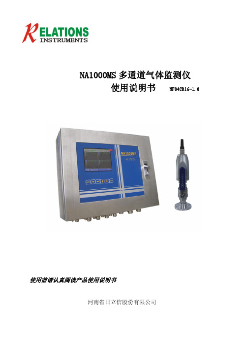
NA1000MS 多通道气体监测仪由 NA1000MR 型监控主机和 NA1000D 型变送器构成(见 图 1-1),用于监测发电机中氢气爆炸下限以内的含量,可带多个检测头,对多点同时 集中控制。本系统采用高性能传感器,由监控主机提供恒流电源,将氢气气体浓度信号 转化为电信号送入主机,大屏幕 LCD 直接显示多路氢气浓度和报警。当环境氢气的浓度 达到或超过预置报警值时,报警器立即发出报警信号,以提醒及早采取安全措施,防止 发生爆炸、火灾事故,从而保障安全生产。
第四章 变送器 ....................................................................................................................20 4.1 NA-1000D 变送器介绍...........................................................................................20 4.2 变送器标定................................................................................................................20
(1)警示说明
危险 在紧急的危险状态。 不回避就有可能造成人受重伤或死亡事故。
警告 告诉你潜在的危险。 如果没有做好预防措施有可能造成人受重伤或死亡事故。
JKL-8漏氢监测仪板式中文说明书
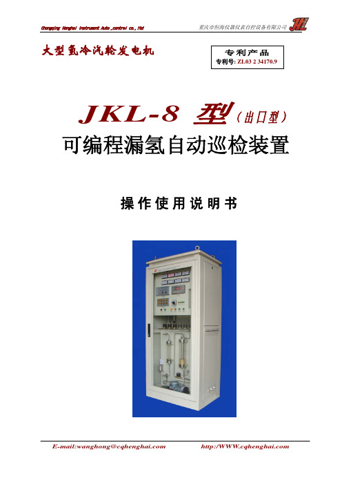
大型氢冷汽轮发电机
重庆市恒海仪器仪表自控设备有限公司
专利产品
专利号: ZL03 2 34170.9
JKL-8 型(出囗型)
可编程漏氢自动巡检装置
操作使用说明书
E-mail:wanghong@
重庆市恒海仪器仪表自控设备有限公司
9、严格执行质量保证及质量寿命工序:
装置的分析仪器在装机之前已经反复老化及校准,并与装置同时在出厂前做 168H 后
检验合格,无需在现场做仪表校准程序。
10、独特而先进的流程设计:
装置采取单台仪表集中分析,这样使分析的确认在一个较先进的设计完善的仪器中进
行,从而保证了数据的准确性。在正常使用下,本装置氢分析仪系统可连续运行 8-10 年无
而定点在需要连续监测的点连续监测。
4、对盘面的仪表及操作件采取了保护措施:
所有显示件、操作件及仪表都内置在可视的有机玻璃后面,避免了施工安装过程中的
损坏。
5、增加柜体防护等级:
柜体采用国家标准万能拼装柜型,其结构的防护等级符合国标“GB4208-93”外壳防
护等级(IP 代码)的“IP64D”级。
6、采用防爆设计:
2、本装置与被测取样点一一对应。因此排管时注意顺序,切勿颠倒(测点名牌在本
机入口处)。它的 8 个管道接口分别与发电机的汽端、励端(二个点),定子线圈冷却水箱
(一个点),封闭母线(三个点),CT 装置附近(二个点心)连接。
本装置取样点安装原则:即发电机氢冷系统的密封部位或旋转密封部位在漏 H2 时, 氢气人进入大气而且迅速上升。因此检测点应安装在泄漏部位的空气侧的上部。
NA1000MS发电机漏氢检测中文说明书
NA1000MS发电机漏氢检测中文说明书NA1000MS发电机漏氢检测中文说明书【章节一、引言】1.1 说明书目的本文档旨在详细介绍NA1000MS发电机漏氢检测的原理、操作流程及相关注意事项,以便用户能够正确、安全地操作该设备。
1.2 文档范围本文档适用于NA1000MS发电机漏氢检测设备的用户及相关人员。
【章节二、概述】2.1 设备简介NA1000MS发电机漏氢检测设备是一种先进、可靠的设备,用于检测发电机在运行过程中可能出现的氢气泄漏情况,并提供及时的预警。
2.2 检测原理该设备基于氢气的物理性质和传感技术,通过监测和分析发电机内外气体的组成和浓度变化,判断是否存在氢气泄漏。
2.3 主要特点NA1000MS发电机漏氢检测设备具有以下特点:- 高灵敏度:能够检测微量氢气泄漏;- 实时监测:能够实时监测气体浓度变化;- 精准预警:在氢气泄漏情况出现时,能够及时发出预警信号;- 易于操作:操作简单,用户友好。
【章节三、操作流程】3.1 准备工作3.1.1 检查设备是否完好,并进行必要的维护和校准。
3.1.2 确保设备接通电源,并处于正常工作状态。
3.2 检测操作3.2.1 进入检测模式:按下设备上的启动按钮,进入检测模式。
3.2.2 检测环境准备:将设备放置在待测发电机附近,确保周围环境清洁,无干扰。
3.3 结果分析3.3.1 监测数据显示:观察设备上的监测数据显示,了解气体浓度变化情况。
3.3.2 预警信号判断:根据设备发出的预警信号,判断是否存在氢气泄漏情况。
3.3.3 处理措施:根据检测结果,采取相应的处理措施,维护发电机设备的安全运行。
【章节四、注意事项】4.1 操作安全4.1.1 在操作设备时,遵循相关的安全操作规程,确保人身安全。
4.1.2 不得私自拆卸、改装设备,以免影响正常使用及安全性。
4.2 维护保养4.2.1 定期对设备进行维护保养,保持设备的良好状态。
4.2.2 保持设备周围环境整洁,并保持通风良好。
氢气检测仪使用说明书山盾科技

山盾科技Multi Pro 600氢气检测仪用户使用手册v1.0.22014-2015 山盾科技(深圳)有限公司版权所有.该文档所包含的信息为山盾科技(深圳)有限公司专有。
该文档的第一接收人可以复制该文档的全部或部分内容供内部商业活动参考使用,该完整的通知需要出现在所有的副本中。
在复制该文档的任何内容时,使用者应该同意尽一切合理的努力去防止该文档内容在未经授权的情况下使用和传播。
阅读说明用户须知非常感谢您选择使用本公司的Multi Pro 600氢气检测仪(以下简称Multi Pro 600)。
在使用本产品前,请仔细阅读本用户手册。
本手册涵盖产品使用的各项重要信息及数据,用户必须严格遵守其规定,方可保证Multi Pro 600的正常运行。
同时,相关信息可帮助用户正确使用该产品,并获得准确的分析结果,节省由于咨询等服务产生的额外成本。
注意事项本手册介绍了Multi Pro 600的具体应用,以及如何启动、操作和维护。
需特别指出的是,本手册中的警告和安全信息至关重要,能有效地避免不恰当的操作。
本手册所述产品的开发、制造、测试都把适当的安全标准放在首位。
因此,如果用户按照本手册指导进行安装、核准使用和维护,可避免因操作不当而造成的常规使用中的财产损失和人身危害。
本手册内容仅供参考,如有变更,恕不另行通知!安全事项在打开仪器外壳前,必须切断电源。
切勿擅自或任意拆卸传感器。
请在符合仪器正常运行的环境条件下使用仪器。
在仪器安装和操作的过程中请严格遵守国家相关标准要求。
公司联系方式目录阅读说明 (1)用户须知 (1)注意事项 (1)安全事项 (1)公司联系方式 (1)1 简介 (4)1.1 产品概述 (4)1.2 产品特点 (4)2 技术参数 (5)3 仪器安装 (6)3.1 安装场所 (6)3.2 仪器结构尺寸 (7)3.3 安装说明 (7)3.4 电缆选择 (7)3.5 接线方式 (8)3.5.1 接线端子图解 (8)3.5.2 3线制4-20mA接线图 (10)3.5.3 4线制4-20mA接线图 (10)3.5.4 4线制RS485信号传输接线图 (11)3.5.5 2路4-20mA信号输出接线图 (11)3.6 报警继电器接线方式 (12)4 开始监测 (12)4.1 线路检查 (12)4.2 仪器监测状态 (13)4.2.1 仪器开机自检和预热状态 (13)4.2.2 正常监测状态 (13)4.2.3 一级报警状态 (14)4.2.4 二级报警状态 (14)5 仪器操作 (15)5.1 调零 (15)5.2 标定 (16)5.3 参数设置 (17)6 仪器维护 (17)6.1 传感器使用寿命 (17)6.2 传感器更换 (17)1简介1.1产品概述Multi Pro 600系列氢气检测仪可以24小时实时采集现场所测气体的浓度,并判断是否超过报警阈值,根据判断结果执行对应报警动作,同时将采集的数据和报警信息传送至气体报警控制器,能在各个工业领域起到在线监测和记录的作用。
氢气露点仪HMT360中文说明书
第一章概述安全:使用仪表前,一定要阅读说明书中的注意事项!警告:表明您现在已经处于非常危险的区域。
如果您不仔细阅读每一个细节,将非常危险甚至危及您的生命。
小心:这一条告诉您现在处于潜在危险之中。
如果不仔细阅读这一点,仪表将被损坏甚至所有重要的数据都将丢失。
注意:这一条告诉您关于仪表的重要的使用信息。
ESD保护释放静电(ESD)将能抑制或延迟损坏仪表的电路。
Vaisala公司在这些产品中专门设计了防止ESD的保护装置。
然而如果触摸,移动或在设备中插入任何设备时释放静电也可能损坏仪表。
为了确保您自己没有静电,请您先通过一些措施使您所带的静电完全释放再接触此仪表。
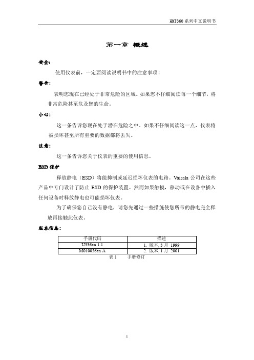
版本信息:第二章综述HMT360系列传感器内置微控制器,能同时在危险区域测量相对湿度(RH)和温度(T)的防爆(EX)级别的仪表。
符合欧洲标准·EU 管理的76/117/EEC标准:EN50014和EN50020标定:EE x ia ⅡC T5HMT360 配备有可选的Lon Works® 模拟接口,且其仅遵循76/117/EEC 标准。
1:输出参数传感器有一个现场显示和两路电流输出信号。
传感器的测量和计算参数如下:*仅对2:探头的选择HMT360传感器系列的传感单元、探头和电缆的长度有多种选择。
不同的探头类型如下:HMP361:探头为墙面安装;HMP363:探头为狭小空间设计的(Φ13.5mm);HMP364:探头为压力环境设计的,承受的压力可达100bars;HMP365:探头为高温环境设计的,温度可达180℃;HMP368:探头安装在压力管路中可承受40bars;压力紧固使用铆固螺母;传感器电缆的长度有2,5和10米供选择(除了HMP361)。
3:维护传感器的电路部分同探头一样可以在现场移动和更换;详见图3-1,图3-2和图9-1。
所有其他的维护出厂前已经完成。
如果传感器被损坏,请与Vaisala公司或其当地的代理商联系,并将仪器的错误和数据以及其尽可能详尽的情况写明。
泄漏测试仪操作说明

泄露测试仪说明书泄露测试仪在下列环境条件下可以绝对安全地使用:•室内使用•海拔3000公尺以下•周围操作温度从5°C到45°C•不会凝结的100%最大相对湿度•供应网络电压的波动不超过正常电压的15%•暂时过电压符合CEI664标准的安装类目II•CEI664标准的二级污染测试环境注意事项* 尽量保持测试环境清洁。
一般注意事项* 使用仪器前应阅读本使用手册。
* 所有与本仪器连接的电子装置必须依据其需要配备合乎标准的安全系统(保险丝﹑断路器…)。
* 为了避免电磁干扰,接到仪器的电线长度不应超过两公尺。
•电子主体必须接地线。
* 维修前请先拔掉与仪器相接的所有电子装置。
* 进行气动组件组合时应切断操作所需的空气供应* 当仪器通电后请勿打开它。
* 避免液体喷溅到仪器。
泄露测试仪简介泄露测试仪主要用来测试生产线上的气密零件,它们是特别为全自动和半自动工作台所设计。
其基本原理是测试两个充满相等压力的测试和标准零件之间差压的微小变化或下降。
原理图如下图1所示。
样品零件测试零件差压传感器压力传感器测试气体泄露仪用户?阀?阀图1它具有8开关量输入5继电器输出,配合系统的用户自定义编程,可以接受外部信号的控制,同时可以控制电磁阀、继电器等元件,从而轻松实现设备的全自动化。
测试特性:2.1差压测试测试范围精度最大分辨率0~1000Pa 满量程的3% 0.25pa0~10000Pa 满量程的3% 2.5pa2.2测试压力测试测试范围精度最大分辨率0~100KPa 满量程的1.5% 满量程的0.025%0~250KPa 满量程的1.5% 满量程的0.025%2.3机械调压阀0~400Kpa3.差压测试的主要类型有三种测试类型﹕直接测试﹑间接测试和密封零件测试。
这三种测试方法分别应用于压力下和真空条件下的测试。
其组态是依据应用而决定,且必须在仪器使用前设定。
3.1.直接/压降测试在测试和标准零件的压力被充到所要求的水平后,HRS泄露测试仪测试被平衡阀分开的两容积之间的差压。
testo 316-1-EX 气体泄漏检测仪使用说明书

testo 316-1-EX gas leak detector 0560 3163Instruction manualContents Contents1About this document (3)2Safety and disposal (3)2.1Security (3)2.2Disposal (4)3Product-specific information (5)4Intended use (5)4.1Special conditions for the usage (6)5Product description (7)5.1Instrument overview (7)6First steps (8)6.1Getting to know the product (8)6.1.1Switching the instrument on and off (8)6.2Establishing a Bluetooth® connection (9)6.2.1Establishing a Bluetooth® connection to the testo Smart App (9)7Using the product (10)7.1Controls (10)7.1.1Implementing settings (12)7.2Carrying out a function test (15)7.3Carrying out gas detection (15)8Maintaining the product (19)8.1Charging the rechargeable battery (19)8.2Cleaning the instrument (19)8.3Cleaning the sensor (19)9Technical data for testo 316-1-EX (21)10Tips and assistance (22)10.1Questions and answers (22)10.2Error codes (22)10.2.1Hard Reset (22)10.3Accessories and spare parts (22)11Support (22)1 About this document1 About this document•The instruction manual is an integral part of the instrument.•Please keep this documentation available for future reference.•Always use the complete original instruction manual.•Please read this instruction manual through carefully and familiarize yourself with the product before putting it to use.•Hand this instruction manual on to any subsequent users of the product. •Pay particular attention to the safety instructions and warning advice in order to prevent injury and damage to the product.2 Safety and disposal2.1 SecurityGeneral safety instructions•Only operate the product properly, for its intended purpose, and within the parameters specified in the technical data.•Do not apply any force.•Do not operate the instrument if there are signs of damage on the housing, mains unit or connected cables.•Dangers may also arise from objects to be measured or the measuring environment. Always comply with the locally valid safety regulations when carrying out measurements.•Do not store the product together with solvents.•Do not use any desiccants.•Only perform maintenance and repair work on this instrument that is described in this documentation. Follow the prescribed steps exactly when doing the work.•Use only original spare parts from Testo.•Only use the original mains unit from Testo.•The substantial safety and health requirements are fulfilled in accordance with the following norms:o EN IEC 60079-0:2018o EN 60079-11:2012•The gas leak detector must not be exposed to the processes that generate significant electrostatic charges.32 Safety and disposal4Batteries• Improper use of batteries may cause the batteries to be destroyed, or lead to injury due to current surges, fire or escaping chemicals.• Do not expose the batteries to heavy impacts, water, fire or temperatures in excess of 60 °C.• In the event of contact with battery acid: rinse affected areas thoroughly with water, and if necessary consult a doctor.• Only charge the battery using the original Testo mains unit supplied.• Immediately stop the charging process if this is not completed in the given time.WarningsAlways pay attention to any information denoted by the following warnings. Implement the precautionary measures specified!DANGER Risk of death!WARNINGIndicates possible serious injury.CAUTIONIndicates possible minor injury.Indicates possible damage to equipment.2.2 Disposal• Dispose of faulty rechargeable batteries and spent batteries in accordance with the valid legal specifications.• At the end of its useful life, deliver the product to the separate collection point for electric and electronic devices (observe local regulations) or return the product to Testo for disposal.•WEEE Reg. No. DE 753343523 Product-specific information 3 Product-specific information•Do not carry out measurements on live components.•Do not operate the instrument in environments above 80 %RH (condensing). •Observe the permissible storage and transport temperatures and the permissible operating temperature (e.g. protect the measuring instrument from direct sunlight)!•Always carry out a function test before searching for gas leaks.•If the instrument is misused or subjected to force, all warranty claims will be voided!•Do not allow the sensor to come into contact with moisture or acids, as it will react cross-sensitively.4 Intended useThe testo 316-1-EX is a gas leak detector for the short-term detection of leaks in gas systems in potentially explosive atmospheres of the classATEX II 2 G Ex ib IIC T1Gb according to Directive 2014/34/EU (ATEX).The following substances can be detected:•Methane CH4•Propane C3H8•Butane C4H10•Hydrogen H2The instrument is not suitable for precise measurement of the gas concentration.A flammable substance in the air has a lower explosive limit (LEL) and an upper explosive limit (UEL).The air/gas mixture is flammable anywhere between these two limits, potentially leading to an explosion (critical range).Below the LEL, the mixture is too lean for an explosion, and above the UEL it is too rich (non-critical range).The explosive limits depend on the substance:-Methane CH4: LEL 4.4 vol.% / UEL 16.5 vol.%-Propane C3H8: LEL 1.7 vol.% / UEL 10.9 vol.%-Butane C4H10: LEL 1.4 vol.% / UEL 9.4 vol.%-Hydrogen H2: LEL 4.0 vol.% / UEL 77.0 vol.%54 Intended use 6- Do not use the instrument as a monitoring instrument for personal safety! The instrument is not protective equipment!- Do not use the instrument as a gas analyzer! The sensor detects almost all combustible gases alike.4.1 Special conditions for the usage • The gas leak detector must only be used in potentially explosive atmospheres of the IIC T1 class.• The gas leak detector must only be used in the ambient temperature range from -5 °C to +50 °C.• The gas leak detector must not be exposed to the processes that generate significant electrostatic charges.• The gas leak detector must only be recharged using the corresponding charger outside of a potentially explosive atmosphere in the ambient temperature range from 0 °C…+45 °C.• The charging voltage must not be higher than U m = 8.5 V.This voltage can be provided using one of the following measures in accordance with IEC 60079-14:o making sure that U m in a SELV/PELV system can not be higher than50 V AC or 120 V DC;o using a safety transformer that fulfils all requirements according toIEC 61558-2-6 or an equivalent technical standard;o connecting it directly to an instrument that fulfils all requirementsaccording to IEC 60950 and its successors, IEC 61010-1 or anequivalent technical standard; ousing a direct power supply source, e.g cells or batteries.• The expected short-circuit current during the charging process must not exceed 50 A.Use only the supplied mains unit to fulfil all charging requirements.5 Product description5 Product description5.1 Instrument overviewSymbol explanation76 First steps86 First steps6.1 Getting to know the product6.1.1 Switching the instrument on and off Switching onOnly switch on the instrument in fresh air, since automatic zeroing is carried out when the instrument is switched on. The ambient temperature and ambient humidity during zeroing should correspond to the ambient conditions at themeasuring location. If necessary, zero again manually at the measuring location (switch off and on again).If the unit is not used for a prolonged period of time, the sensor willbecome contaminated. Particularly if the instrument has not been in operation for a prolonged period of time (> 2 weeks), it should be left switched on for a while before being used. The longer it has not been in operation, the longer this additional warming-up phase should be.Please note that the instrument switches itself off by default after 10 min of inactivity.1 Press and hold down (1 sec) the On/Off key.Warm-up phase (HEAT)↓ The instrument starts up. With regular use, the warm-up period takes approx. 30 sec and is symbolized by the text “HEAT” and acountdown.As long as the sensor LED is flashing orange, the instrument is not ready for use.↓ Following the warm-up period, the measurement view is displayed.Self-cleaning (CLN)↓ If the sensor is dirty, the warm-up phase is followed by the sensor cleaning phase. This usually happens when the instrument has notbeen used for several days. The self-cleaning is symbolized by the text “CLN” and a countdown.Switching offCAUTION Caution! Risk of burns due to hot sensor head after prolongedoperation.- Before touching the sensor head or packing the instrument: switchinstrument off and let the sensor head cool down.6 First steps91 Press and hold down (1 sec) the On/Off key.↓ The instrument is switched off.Auto OFFAfter 10 minutes of inactivity (no user input, no gas concentration above the warning threshold), the instrument switches itself off. The switch-off is signalled beforehand by an alarm sound, red flashing of the sensor LED and a 10 sec countdown.You can prevent the instrument from switching off by pressing any key within 10 seconds.Enabling/disabling the Auto-OFF function:1 Press the Sound and UNIT keys simultaneously for 1 sec.↓ Enabling/disabling is confirmed by "AOFF ON" or "AOFF OFF".6.2 Establishing a Bluetooth ® connectionThe instrument can be connected to the testo Smart App viaBluetooth ® connection.✓ The gas leak detector is switched on.6.2.1Establishing a Bluetooth ® connection to the testo Smart AppTo establish a connection via Bluetooth ®, you need atablet or smartphone with the Testo Smart App alreadyinstalled on it.You can get the App for iOS instruments in the App Storeor for Android instruments in the Play Store.Compatibility:Requires iOS 13.0 or later/Android 8.0 or later,requires Bluetooth ® 4.2.1 Open the testo Smart App.↓ The app automatically searches for Bluetooth ® devices in the vicinity.2 In the Bluetooth menu, check whether the required instrument is connected.7 Using the product10 ↓ If necessary, switch the instrument to be connected off and on again to restart the connection mode.7 Using the productFor technical reasons, the accuracy of the sensor improves with longer operating time of the sensor.For accurate measurements in ppm or calibrations, the device must be switched on for at least 10 minutes (after the warm-up phase).Please note that the instrument switches itself off by default after 10 min of inactivity. You can avoid this by disabling the Auto-off function (see chapter 6.2.1).Lighters are only suitable to a limited extent for a function test due to the different liquid gas mixtures used in commercial lighters and the selectivity of the sensor based on the gas set (GAS button).The gas leak detector can be used in conjunction with the testo Smart App .7.1 Controls✓ The instrument is switched on.✓ The app is installed on the smartphone and connected to theinstrument via Bluetooth ®.↓ Settings and controls are primarily carried out on the instrument and are transferred to the app. To a lesser extent, control via app is also possible (selection of gas type).7 Using the product1 Sound / Illumination key2 On/Off / GAS key3 Bar display4 Mode5 Measurement parameter6 Display for alarm signal, Bluetooth®, charge level7 Maximum measured value8 Current measured value7 Using the productThe Main menu can be accessed via the icon at top left. To exit the main menu, select a menu or right-click on the guided menus. The last screen displayed is shown.7.1.1 Implementing settingsSelecting, opening and setting functions1 Press the relevant key to select the functions.Secondary assignment (long press)All keys with a white corner have a secondary assignment, which can be selected by pressing and holding the key (1 sec).Adjustable functionsEnsure correct settings: all settings are transferred immediately. There is no Cancel function.7 Using the product Measurement parameterDisplay illumination / sensor LED(long press)Alarm soundUnit (long press)7Using the product Max. zeroing (long press) Zeroing7 Using the product7.2 Carrying out a function test1 Apply low-concentration gas to the sensor (max. 10 sec).↓If the sensor does not respond (no alarm), the instrument is defective and must no longer be used. The instrument must be taken to theservice centre for repair.Due to the selectivity of the sensor, gas equivalents are not suitable forchecking the function and especially not for calibrating the sensor.7.3 Carrying out gas detectionHave the instrument serviced annually by the manufacturer.Testing natural gas lines or hydrogen lines:Methane (main component of natural gas) or hydrogen are lighter thanair, detection should be carried out above the pipe / suspected leak.Testing propane and butane gas lines: Propane and butane are heavierthan air, detection should be carried out below the pipe / suspectedleak, starting from the bottom and working upwards.Selecting the gas to be detected1 Select the gas types via the GAS key or the testo Smart App using the3-point menu in the top right corner of the output field↓After switching on the instrument, the process of cycling through starts with methane (CH4).Automatic identification of common gas typesThe gas is automatically detected and indicated by a flashing gas icon on the display if a gas concentration currently applied to the sensor has characteristics of a different gas type than is currently selected.For technical reasons, this is subject to uncertainty and is intended as a support for users, and must therefore always be checked by the user.7Using the productSelecting the mode1 Press the MODE key to switch between modes.MODE 1 is suitable for measuring the general gas concentration in indoor areas.↓The gas concentration is indicated bythe increasing bar display.MODE 2 is suitable for locating a leak. In this mode, rising or falling concentration values are output.↓At the beginning, two bar segmentsare displayed in the middle.At the same time, the sensor LEDflashes in a colour corresponding tothe concentration value and an audiosignal is emitted at the samefrequency.↓As the concentration increases, adeflection to the right is displayed.The frequency of the flashing/audiosignal increases.As the concentration decreases, adeflection to the left is displayed. Thefrequency of the flashing/audio signaldecreases.7 Using the product↓If the concentration remains unchanged, the deflection moves back to the centre. The deflection is reset manually using the [--> 0 <--] key Carrying out the measurement1 Move the sensor head as close as possible and at low speed (approx.< 2 cm per second) over the components that are to be checked forleaks.The surface of the sensor must not be covered.↓•Concentration < 100 ppm: The sensor LED and the displayillumination light up green. In addition, the bar display increases.•Concentration > 100 and < 999 ppm: The sensor LED and the display illumination light up yellow. In addition, the bar displayincreases.•Concentration > 999 ppm: The unit changes to VOL% and the bar display increases.•Concentration > 9999 ppm / > 0.99 VOL%: The sensor LED and the display light up red (alarm threshold).↓When the lower explosive limit is reached, ">LEL" is displayed. Higher values are not displayed.To locate the leak, it is advisable, in the case of these larger leaks, toswitch to MODE 2 in order to receive feedback via audio and flashingsignals.↓If the warning threshold (100 ppm) is exceeded, the sensor LED and display illumination light up yellow. If the acoustic alarm is enabled, anadditional warning sound is emitted when the warning threshold isexceeded, the frequency of which increases as the concentrationincreases, and changes to a continuous tone when the second alarmthreshold (10,000 ppm) is exceeded.Changing unitsBy default, the display shows ppm (concentration in parts per million). From a concentration of >999 ppm, the display changes to vol% (1000 ppm=0.1 vol%). Higher concentrations in ppm are also displayed in the app.In addition, %LEL (the percentage of the lower explosive limit that has been reached) can be selected.1 Press the unit key to change the unit.Carrying out manual zeroingThe zero point can only be set manually if the currently detected gas concentration is below the max. 250 ppm (max. 250 ppm can be suppressed). For example:•150 ppm (≤ 250 ppm): are completely suppressed (display: 0 ppm)7Using the product•1000 ppm (> 250 ppm): 250 ppm are suppressed (display: 750 ppm)Gas concentrations present at the time of zeroing are suppressed byzeroing. As a result, the displayed reading no longer corresponds to thereal gas concentration.✓ The instrument is in measurement view.1 Briefly press [--> 0 <--].↓The zero point for the current reading is reset or the currentsuppression is cancelled.↓On instruments with a display, the suppression of the reading is symbolized by an arrow pointing downwards on the display.The maximum reading can be zeroed using [max --> 0 <--].After the measurement1 Ventilate the sensor thoroughly after each use. To do this, place theinstrument in fresh air for approx. 2 minutes before using it again.8 Maintaining the product8 Maintaining the product8.1 Charging the rechargeable batteryDANGER- Do not charge the rechargeable battery in potentially explosive atmospheres!Only charge the battery using the original Testo mains unit supplied. The instrument indicates that the battery needs to be charged via a flashing battery symbol.1 Connect the instrument to the mains via the mains unit. To do this,insert the plug of the mains unit into the charging socket on theunderside of the instrument.When the mains unit is plugged in during operation, the instrumentswitches off due to ATEX regulations.The instrument can become very warm during charging and should notbe held in your hand.8.2 Cleaning the instrument1 If the housing of the instrument is dirty, clean it with a damp cloth.Do not use any aggressive cleaning agents or solvents! Mild householdcleaning agents and soap suds may be used.Storage & transportationTo prevent contamination of the sensor, please do not store or transport the instrument in an environment where any tobacco smoke, foul air, oils, greases, silicones, evaporating liquids or gases are present. Any sensor that is contaminated as a result of storage or transportation must be cleaned before use, see Cleaning the sensor.Regular inspectionTesto recommends having the gas leak detector inspected by an authorized service centre every year.8.3 Cleaning the sensorTobacco smoke, dirty air, oils, greases, silicones and evaporating liquids or gases can leave deposits on the sensor surface. Possible consequences are8Maintaining the productreduced sensitivity, distorted displays of gas concentration or display of a background concentration. Clean the sensor if necessary1 Switch on the instrument, allow it to initialize and then switch it off.Repeat this procedure several times.2 If it is dirty, clean the sensor head with a soft, dry cloth.Switching on regularlyIf the instrument is used infrequently, deposits may build up on the sensor. Switching the instrument on prevents these deposits from building up on the sensor. Testo recommends switching the instrument on regularly to avoid deposits building up on the sensor.Changing the sensor headThe instrument has a permanently installed sensor head that can only be replaced by Testo Customer Service.9 Technical data for testo 316-1-EX 9 Technical data for testo 316-1-EX2110Tips and assistance10 Tips and assistance10.1 Questions and answers10.2 Error codesThe error code is shown on the display.10.2.1 Hard Reset1 If you encounter any problems with the firmware, press and hold theON/OFF key for a long time (4 sec.) to perform a reset.10.3 Accessories and spare parts11 SupportYou can find up-to-date information on products, downloads and links to contact addresses for support queries on the Testo website at: .If you have any questions please contact your local dealer or the Testo Customer Service. You can find contact details on the back of this document or online at /service-contact.22Testo SE & Co. KGaACelsiusstraße 279822 Titisee-NeustadtGermanyTelefon: +49 7653 681-0E-Mail:*************Internet: 0970 3263 en 05 - 04.2023。
SF6气体检漏仪说明书

SF6气体检漏仪说明书概述SFe气体检漏仪是测量气体泄漏的新一代产品,它具有灵敏度高、稳定性好、响应速度快、操作简便、移动范围大,可迅速、准确的定性和定量检测SF6断路器和GIS的泄漏点及年泄漏率。
本仪器十分适合于供电部门、安装检修单位和电力试验研究所使用,同时也十分适合SF6高压开关厂作为SF6电器设备及出口产品的配套仪器,从而提高了整体产品的档次。
二、主要技术指标1、最小检测值:1 (X 1 0 一6体积比)2、检测范围:1〜1 0 0 0 (XI 0 ~6体积比)3、响应时间:VI秒4、恢复时间:V 1 0秒5、示值误差:W± 3 %6、重复性:W1%7、传感器静止时最大灵敏度:3 g/年8、指示方式:数字显示和声光讯号9、探枪检测长度:手持式1 0、连续工作时间:5小时1 1、仪器电源:可充电镰氢电池,交直两用1 2、使用环境:温度:一5€〜+4 5 °C相对湿度:W 8 513、整机重量:2公斤1 4、体积:长X宽><高=230mmX 130mmX 45mm三、主要特点1、体积小,重量轻,便携式,手持蛇形探头,连线增加易弯性。
2、灵敏度高:超级感应,对细微的卤素气体有响应,可检每年3g以上气体泄漏量。
3、测量范围宽:仪器可在SF6开关装置的泄漏率范围内检测SFe的漏气量,可两档切换选择。
4、准确度高:仪器采用先进的校验方法校验,给出高准确度的校准线,提高了SF6检漏结果的可信度和定量检漏的精度。
5、显示直观,声光报警:采用数字液晶,带背光显示,具有简便直观的效果。
当有SF6存在时,仪器发出声光报警。
6、反应速度快,恢复时间短:采用新型电路结构,使仪器的反应速度加快,恢复时间缩短,这极大地方便了现场检测。
7、使用时间长:使用时间可达5小时,十分适合于现场,SFe 高压开关厂和研究所使用。
8、可充电电池,一次可连续使用5小时以上。
四、操作步骤1、先将手持式探头上的连接线插头接到仪器液晶显示屏下方的插座上扭紧,然后打开电源开关,“Full- charge ”灯亮,液晶屏显示“欢迎使用”,然后进入第二屏“ 1、运行2、设置”。
氢气检测仪使用说明书-山盾科技
山盾科技Multi Pro 600氢气检测仪用户使用手册v1.0.22014-2015 山盾科技(深圳)有限公司版权所有.该文档所包含的信息为山盾科技(深圳)有限公司专有。
该文档的第一接收人可以复制该文档的全部或部分内容供内部商业活动参考使用,该完整的通知需要出现在所有的副本中。
在复制该文档的任何内容时,使用者应该同意尽一切合理的努力去防止该文档内容在未经授权的情况下使用和传播。
阅读说明用户须知非常感谢您选择使用本公司的Multi Pro 600氢气检测仪(以下简称Multi Pro 600)。
在使用本产品前,请仔细阅读本用户手册。
本手册涵盖产品使用的各项重要信息及数据,用户必须严格遵守其规定,方可保证Multi Pro 600的正常运行。
同时,相关信息可帮助用户正确使用该产品,并获得准确的分析结果,节省由于咨询等服务产生的额外成本。
注意事项本手册介绍了Multi Pro 600的具体应用,以及如何启动、操作和维护。
需特别指出的是,本手册中的警告和安全信息至关重要,能有效地避免不恰当的操作。
本手册所述产品的开发、制造、测试都把适当的安全标准放在首位。
因此,如果用户按照本手册指导进行安装、核准使用和维护,可避免因操作不当而造成的常规使用中的财产损失和人身危害。
本手册内容仅供参考,如有变更,恕不另行通知!安全事项在打开仪器外壳前,必须切断电源。
切勿擅自或任意拆卸传感器。
请在符合仪器正常运行的环境条件下使用仪器。
在仪器安装和操作的过程中请严格遵守国家相关标准要求。
公司联系方式目录阅读说明 (1)用户须知 (1)注意事项 (1)安全事项 (1)公司联系方式 (1)1 简介 (4)1.1 产品概述 (4)1.2 产品特点 (4)2 技术参数 (5)3 仪器安装 (6)3.1 安装场所 (6)3.2 仪器结构尺寸 (7)3.3 安装说明 (7)3.4 电缆选择 (7)3.5 接线方式 (8)3.5.1 接线端子图解 (8)3.5.2 3线制4-20mA接线图 (10)3.5.3 4线制4-20mA接线图 (10)3.5.4 4线制RS485信号传输接线图 (11)3.5.5 2路4-20mA信号输出接线图 (11)3.6 报警继电器接线方式 (12)4 开始监测 (12)4.1 线路检查 (12)4.2 仪器监测状态 (13)4.2.1 仪器开机自检和预热状态 (13)4.2.2 正常监测状态 (13)4.2.3 一级报警状态 (14)4.2.4 二级报警状态 (14)5 仪器操作 (15)5.1 调零 (15)5.2 标定 (16)5.3 参数设置 (17)6 仪器维护 (17)6.1 传感器使用寿命 (17)6.2 传感器更换 (17)1简介1.1产品概述Multi Pro 600系列氢气检测仪可以24小时实时采集现场所测气体的浓度,并判断是否超过报警阈值,根据判断结果执行对应报警动作,同时将采集的数据和报警信息传送至气体报警控制器,能在各个工业领域起到在线监测和记录的作用。
HY-ALERTATM 500 手持式氢气泄漏检测器操作手册说明书
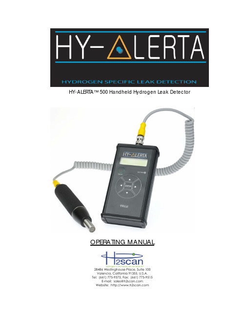
HY-ALERTA™ 500 Handheld Hydrogen Leak DetectorOPERATING MANUAL28486 Westinghouse Place, Suite 100Valencia, California 91355, U.S.A.Tel: (661) 775-9575, Fax: (661) 775-9515E-mail:****************Website: MISSION STATEMENTTo become the leading provider of hydrogen specific safety monitoring and in-line process measurement systems where hydrogen gas is produced, used, consumed, stored and transported.We are committed to providing cost-effective solutions as new installations and replacements for existing hydrogen gas analyzers to OEM customers and through our global distribution network.Our products will achieve worldwide recognition in industrial safety and process applications based on superior products, while maintaining excellent relationships with and ensuring unsurpassed value to our business partners around the globe.CONTENTS1. Description (5)2. Specifications (5)3. Operation (7)3.1 Startup (7)3.2 Shutdown (7)3.3 Battery Level (7)3.4 Normal Operation (7)3.5 Hydrogen-Free Areas (10)3.6 Reset Operation (10)3.7 Zero Operation (10)4. Keypad (11)4.1 Numerical Changes (11)4.2 Top Level Keypad Functions (11)4.3 General Keypad Functions (Also See Section 10) (11)4.4 Information Display (11)4.5 Firmware Rev: (11)4.6 Serial Number: (11)4.7 Calibration Date: (12)4.8 Reset Sensor (12)4.9 Zero Sensor (12)4.10 Verify (12)5. Hydrogen Sensing Considerations (13)6. Bump Test (14)7. Verification (14)7.1 Gases (14)7.2 Gas Connection (14)7.3 Verification Kits (14)8. Battery Charging (16)9. Cleaning (16)10. Troubleshooting (16)11. Menu Structure (17)12. Appendix (21)12.1 European Declaration of Conformity (21)IMPORTANT NOTICESRead and understand this operating manual before installing or using the unit.Only use cables, battery pack, battery charger, and AC/DC power supplyfrom H2scan with this unit.If this equipment is used in a manner not specified by H2scan, the protection provided by this equipment may be impaired.Hydrogen is flammable at 4% in air. Take indications seriously and be prepared to take action. In the event of detection of 4% or higher of a hydrogen gasconcentration there is a high probability of a hazard to safety. Inform localemergency response personnel immediately.LIMITATION OF LIABILITYIn the event of a defect in a product, h2scan shall not be responsible for any direct, indirect, incidental or consequential damages resulting therefrom, including, but not limited to, loss of revenue and/or profit.LIMITED WARRANTYH2scan Limited Warranty: Each hydrogen instrument (“Product”) will conform, as to all substantial operational features, to the Product specifications set forth this Manual and will be free of defects which substantially affect such Product’s performance for twelve (12) months from the ship date for such Product.Must Provide Notice of Defect: If you believe a Product that you believe is defective, you must notify H2scan in writing, within ten (10) days of receipt of such Product, of your claim regarding any such defect.Return Product to H2scan for Repair, Replacement or Credit. If the Product is found defective by H2scan, H2scan’s sole obligation under this warranty is to either (i) repair the Product, (ii) replace the Product, or (iii) issue a credit for the purchase price for such Product, the particular remedy to be determined [by H2scan] on a case-by-case basis.Voided Warranty. H2scan’s 12 Month Limited Warranty is void for any of the following:The unit is opened and the manufacturing seal is brokenUnauthorized repair work performed at the customer’s location or carried out by anyone other than H2scan’s factory trained technicians Equipment or parts that have been tampered with, misused, neglected, mishandled, improperly adjusted, or modified in any way without the written consent of H2scan.Equipment or parts that have been damaged due to shipping, misuse, accidents, mishandling, neglect, or problems with electrical power sources.Repair work performed during the warranty period does not prolong the warranty period past the original period.System operation in incorrect or inappropriate environments.Usage that is not in accordance with system guidelines or an operator’s failure to follow manual instructions.Limitation of Warranty: THE ABOVE IS A LIMITED WARRANTY AS IT IS THE ONLY WARRANTY MADE BY H2SCAN. H2SCAN MAKES NO OTHER WARRANTY EXPRESS OR IMPLIED AND EXPRESSLY EXCLUDES ALL WARRANTIES OF MERCHANTABILITY AND FITNESS FOR A PARTICULAR PURPOSE. YOUR SOLE REMEDY HEREUNDER IS REPAIR OR REPLACEMENT OF THE PRODUCT OR A CREDIT FOR THE PURCHASE PRICE FOR SUCH PRODUCT, THE PARTICULAR REMEDY TO BE DETERMINED BY H2SCAN ON A CASE-BY-CASE BASIS. H2SCAN SHALL HAVE NO LIABILITY WITH RESPECT TO ITS OBLIGATIONS UNDER THIS AGREEMENT FOR CONSEQUENTIAL, EXEMPLARY, OR INCIDENTAL DAMAGES EVEN IF IT HAS BEEN ADVISED OF THE POSSIBILITY OF SUCH DAMAGES. THE STATED EXPRESS WARRANTY IS IN LIEU OF ALL LIABILITIES OR OBLIGATIONS OFH2SCAN FOR DAMAGES ARISING OUT OF OR IN CONNECTION WITH THE DELIVERY, USE OR PERFORMANCE OF THE PRODUCTS.1.DescriptionH2scan believes that protecting lives means being able to locate and findhydrogen leak as quickly as possible. With two sensing elements on the same semiconductor die, the HY-ALERTA™ 500 can detect hydrogen leaks as low as15 ppm and will not saturate or be destroyed when detecting concentrationsof hydrogen up to 100%. The flexible cable allows the sensor probe access to virtually all potential leak sources.2.SpecificationsSensitivity Range: 0.0015% (15 ppm) to 100% hydrogen by volume in air.Response Time: Indication of hydrogen within seconds. Stabilization to final value depends on concentration.Ambient Temperatures: Operating: 0°C to +40 °C Storage: -20°C to +45 °CRelative Humidity: 0-95% non-condensingPower: Internal rechargeable Lithium Ion battery yields over 10 hours of operation and is recharged in 4 hours with included charger. Battery charger input: 100-240VAC, 50-60Hz, 0.6A.Environmental: Indoor/Outdoor UseAltitude up to 2000 meters Pollution degree 2 environmentIngress Protection: IP64 capableCalibration Period: Recommended user Verification/Calibration on a 12 month basis. Weight: 975 g (2.15 lb.) unit and carrying pouch2.2 kg (5 lb.) shipping weight (unit with accessories)Product LifeExpectancy: 10 yearsCertifications:Coiled Cord3.Operation3.1StartupTo power-up the HY-ALERTA™ 500, press and hold the ON/OFF button until the Controller LCD display indicates an operational message.Warning: Only power-up the instrument in a hydrogen-free environment.After power is on, the instrument takes about ten minutes to warm-up. During this time the LCD displays a countdown to completion and the Probe Tip LED is amber. The following operations occur:The Wide Range Sensor® reaches operating temperature.A system self-test is run.Upon successful completion of the above tasks the instrument zeroes itself and automatically switches to normal operation. If an error is detected theinstrument will display an error code (see Section 10).3.2ShutdownTo power-down the HY-ALERTA™ 500, press and hold the ON/OFF button forapproximately two seconds until the Controller LCD display turns off.3.3Battery LevelAfter power-on the BATTERY LED indicates the current battery level (times areapproximate and may vary as the battery ages):Color MeaningGreen more than 60 minutes of operation remainingAmber approximately 15 to 60 minutes of operation remainingRed less than approximately 15 minutes of operation remainingA fully charged battery should last 10 to15 hours, depending on use.There is a small load on the battery when the unit is powered off. This load will discharge the battery of the unit in it’s powered off state in about 6 months.Customers that do not use the device frequently should charge the batteryand perform a bump test with hydrogen gas every one to three months tokeep the battery charged and ready for use.3.4Normal OperationDuring normal operation the instrument is detecting and reporting thehydrogen concentration near the probe tip sensor. Hydrogen readings aredisplayed on the controller LCD and the probe tip LED bar graph array. Note that due to the extreme sensitivity of the sensor, it may take several minutes to return to a near zero (less than 0.001%) reading after exposure to hydrogen. If the instrument does not return to an indication of less than 0.001% after 5minutes in a hydrogen-free environment, then invoke the Reset operation (See Section 3.6).The upper line of the Controller LCD indicates a numerical value or range for the percent hydrogen concentration or peak hydrogen value. The lower line is used to display the hydrogen meter, a logarithmic bar graph ranging from0.001% (10 ppm) to 100% hydrogen by volume. An open box on the bar indicates the last peak value obtained and filled boxes indicate the current value. The following figure describes how to interpret the hydrogen meter:The Probe Tip LED Indicator shows an increase or decrease in hydrogenconcentration. Leak detection is accomplished by watching the Probe Tip LED and the bar graph array and moving the sensor around a potential hydrogen leak.The number of yellow LEDs lit in the Probe LED bar graph array indicates detected hydrogen concentrations in four ranges as noted below:3.5Hydrogen-Free AreasFor the purposes of this document a hydrogen-free area is one with less than5ppm of hydrogen in the air.It may be difficult to find a hydrogen-free area in a facility where hydrogen is used. Nearby rooms, or even the entire building, may not be hydrogen free.To check these areas reset or zero the sensor outside, away from any hydrogen tanks, pipes, or other potential sources. Walk through the facility, watching the sensor. It is surprising how far low levels of hydrogen can spread.If the sensor is zeroed or reset in hydrogen, there will be a negative offset in the readings that could compromise the sensor’s ability to find small leaks.3.6Reset OperationThe Reset Operation is used to speed recovery from hydrogen exposure.It can be invoked from the keypad while in the top menu level (measuring hydrogen) by pressing and holding ◄►(left and right arrow buttons simultaneously) or from the Reset Menu (see Section 4). Once invoked the user is asked to confirm the operation by pressing the ENTER key. Pressing any other key will abort the operation. During Reset the LCD indicates a count down to completion and the Probe tip LED is yellow.3.7Zero OperationThe Zero Operation is used to zero the hydrogen reading if the instrument is reporting low levels (0.001% to 0.01%) of hydrogen when no hydrogen is present. This operation can be invoked from the keypad while in the top menu level (measuring hydrogen) by pressing and holding ◄ (left arrow button) or from the Reset Menu (see Section 4). Once invoked the user is asked to confirm the operation by pressing the ENTER key, pressing any other key will abort the operation.4. Keypad4.1 Numerical ChangesIn the following sections when queried to change a numeric value the ▲ (up arrow) and ▼ (down arrow) keys are used to increment/decrement the value based on the selected digit. If the ones digit is selected the value willincrement/decrement by one (9 increments to 10, 10 decrements to 9). The ◄ (left arrow) and ► (right arrow) keys are used to select another digit. Tochange a value of 0 to 100 first select the hundreds digit then press the ▲ up arrow. Pressing ◄► (the left and right arrows simultaneously) will clear any changes made and restore the previous value. Once the correct value is displayed press the ENTER key to save it. 4.2 Top Level Keypad FunctionsWhile in the hydrogen measurement screen, the keypad has these functions:Key Function ENTER Go to the Information Display menu . ▲ Display the peak hydrogen reading. ▼ Display the current hydrogen concentration. ► Clear the peak hydrogen value. ◄ Zero the sensor (see Section 3.7). ◄► Reset the sensor (see Section 3.6).4.3 General Keypad Functions (Also See Section 11)4.4 Information DisplayThe Information Display menu allows the user to view useful information about the instrument including firmware revisions, serial number, and calibration date. Enter it by can be entered by pressing and holding the ENTER button. 4.5 Firmware Rev:This displays the sensor pod and controller firmware. The left most number preceded by an ‘S’ is the Probe firmware revision. The right most number preceded by a ‘C’ is the Controller firmware revision. For example: S1.23 C2.34 for Probe firmware version 1.23 and Controller firmware version 2.34 4.6 Serial Number:This displays the product serial number. For example: 50123Key Navigation Editing Values Query Answer ENTER Enter submenu Select Value Yes ▲ Previous Menu Increase Value No ▼ Next Menu Decrease Value No ► Enter Submenu Move Cursor Right No ◄ Exit Submenu (Back) Move Cursor Left No ◄► Exit Configuration Undo ChangesNo4.7Calibration Date:This displays the date of last factory calibration, MM/DD/YY. For example: 5/8/06 for 8 May 2006.4.8Reset SensorThe Reset Sensor menu is used to invoke the Reset Operation as described in Section 3.6.4.9Zero SensorThe Zero Sensor menu is used to invoke the Zero Operation as described in Section 3.7.4.10VerifyThe Verify menu shows the date of the last field verify and allows the user to invoke the Verify function in Section 6.5.Hydrogen Sensing ConsiderationsFrom any given source, hydrogen gas disperses rapidly and generally upward due to its very low density compared to air. Understanding this behavior allowsa more effective search for hydrogen leaks.The hydrogen plume from a leak generally spreads in a roughly conical shape that is easily disturbed by environmental conditions. Certain conditions such as pressure, temperature, and leak size may act together to change the shape of the hydrogen plume from a cone to a laser-like beam. This makes finding aleak more difficult.If the sensor element is near (and above) the leak, the concentration will likely be higher but the leak may be difficult to locate. As hydrogen dissipates theconcentration decreases. Generally, greater distances will increase thechance of intercepting the leak stream, but if the sensor is too far away, theresponse may be too weak to detect.When drafts or air currents are present, hydrogen will tend to be dispersed.Testing for hydrogen leaks downwind of the leak area may increase thechance of detecting the leak.If hydrogen is rising in an enclosed building the hot air near the ceiling mayslow the hydrogen’s rise. Thus, sensing hydrogen near ceiling areas with hightemperatures present may not be as effective as at a lower level.Low temperatures can also affect the behavior of hydrogen. Hydrogen stored in a liquid state is at an extremely low temperature. The low temperature ofany escaping hydrogen will be of a higher than normal density and mayinitially move downward. As the hydrogen warms, it will begin to rise upward.When checking for a leak in areas where liquid hydrogen is stored, check both above and below the area of concern.6.Bump TestA bump test is recommended every three months. The purpose of a bump testis to verify that the sensor is active, detecting hydrogen and verifying that the sensor is within the pre-set factory tolerance for accuracy. To performs a bump test perform the following:In a non-hydrogen environment, power on the instrument. Once theinstrument has gone through its standard 10 minute warm-up, use thecalibration cup that accompanies the HY-ALERTA™ Model 500, and apply 2% hydrogen to the probe sensor. Let the 2% hydrogen flow for a minimum of 3-5 minutes. After 3-5 minutes the concentration value registered on the LCDdisplay should read between 1.6% to 2.4%, which is within factory tolerance. If the 2% reading is below 1.6% or above 2.4% the instrument should go through a Verification test as outlined below.7.VerificationVerification is performed in a non-hydrogen environment to confirm that theHY-ALERTA™ Model 500 is operating properly and within the pre-set factorytolerance for calibration. The recommended verification interval is every 12months, or after a 2% bump test has been performed and the indicated values on the LCD display were outside the stated tolerance as outlined in Section 6.If the verification fails, then it should be repeated one more time.The HY-ALERTA Model 500 requires calibration only if it fails the secondverification. It cannot be field calibrated and must be returned to h2Scan for calibration service. An optional NIST traceable certificate is available uponrequest.7.1GasesVerification requires the availability of the following certified gases:2.00% hydrogen by volume in air (20,000 ppm)0.10% hydrogen by volume in air (1000 ppm)Zero grade, hydrogen-free air. Ambient air can be substituted if it ishydrogen-free.7.2Gas ConnectionGases are applied to the unit through the use of the Calibration Cup Assy. (P/N 50000009) available from H2Scan.7.3Verification KitsCustomer-specific Field Verification Kits for the HY-ALERTA™ 500 are available from H2scan.The field verification function allows the user to check the instrument’s calibration. Details on this function can be found in Table 1 on page 19. If the unit passes verification, calibration is not required at this time.If the unit fails verification, the unit should be returned to the factory for calibration.8.Battery ChargingEnsure the unit is powered OFF.Disconnect the coiled cord from the controller.Connect the battery charger to the controller.Using the appropriate A/C plug adapter for the region of use, plug the battery charger into the A/C supply.The battery charger indicator light will illuminate according to charge status as follows:Off No BatteryFlashing Green Fast chargingSteady Green Fully chargedSteady Amber StandbyFlashing Red ErrorNOTE: Complete charging may take up to 4 hours for a fully dischargedbattery.9.CleaningIf the unit becomes soiled, clean the unit with a lint-free cloth. Use special care when cleaning the handheld probe assembly. Small debris or other materialmay collect over the sensor tip. Clean the tip with a gentle wiping with a clean, damp, lint-free cloth or paper. Do not use chemicals or soap.10.TroubleshootingSymptom Possible Cause ActionSensor Error The probe isdisconnected from thecontroller.Turn off the instrument and verifythat the probe is properlyconnected to the controller.Error 88 Faulty capacitor Turn off the instrument.Error 40 The PCB temperature istoo high. Turn off the instrument. Let it cool.Error 20 The sensor temperatureis incorrect.Turn off the instrument.Battery LED is red The battery is very low. Charge the battery completely. See Section 8.Unit won’t turn on The battery is dead. Charge the battery completely. See Section 8.If the recommended action does not solve the problem, the HY-ALERTA 500 should be returned to the factory for repair.11.Menu StructureTable 1 - Verify ProcedureStep Display Userresponse1 Verify Sensor Press ENTER2 Verify SensorContinue?Press ENTER to Verify sensor, L to exit.3 Verify SensorIn ProgressVerify Test begins.4 Apply 0.000%H2Continue? With the Calibration Cup that accompanies the HY-ALERTA TM 500, apply hydrogen-free, zero air to the Probe sensor. The Probe Tip LED will remain Green. Press ENTER.5 Apply 0.000%H2In Progress0% Verify Test starts.6 Apply 0.000%H2SettleChecking sensor temperature.7 Apply 0.000%H2Wait xxxx Wait for sensor reading to stabilize until xxxx = 0.8 Apply 0.000%H2Finding AverageMeasuring sensor response to test gas.9 Apply 0.100%H2Continue? With the Calibration Cup, apply 0.1% hydrogen to the Probe sensor. The Probe Tip LED will change from Green to Red. One (or two) yellow LEDs in the LED BarGraph Array will turn on. Press ENTER.10 Apply 0.100%H2In Progress0.1% Verify Test starts.11 Apply 0.100%H2SettleChecking sensor temperature.12 Apply 0.100%H2Wait xxxx Wait for sensor reading to stabilize until xxxx = 0.13 Apply 0.100%H2Finding Average Measuring sensor response to test gas. Visually verify that 1-2 yellow LED’s are lit up in the probe tip. If not the unit needs factory calibration14 Apply 2.000%H2Continue? With the Calibration Cup, apply 2.0% hydrogen to the Probe sensor. The Probe Tip LED will remain Red. Three yellowLEDs in the LED Bar Graph Array will turn on. Press ENTER.15 Apply 2.000%H2In Progress2.0% Verify Test starts.16 Apply 2.000%H2SettleChecking sensor temperature.17 Apply 2.000%H2Wait xxxx Wait for sensor reading to stabilize until xxxx = 0.18 Apply 2.000%H2Finding AverageMeasuring sensor response to test gas.19 Enter Date:1.0000 M Enter the current month (1-12) using the ▲ (up arrow) and ▼ (down arrow) keys.20 Enter Date:1.0000 D Enter the current day (1-31) using the ▲(up arrow) and ▼ (down arrow) keys.21 Enter Date:6.0000 Y Enter the current year (7=2007, 12=2012, etc.) using the ▲ (up arrow) and ▼(down arrow) keys.22 Verify SensorPassedVerify is complete, press any key.HY-ALERTA TM 500 Handheld Hydrogen Leak Detector OPERATING MANUAL90000002 R10, ECO #11-035Page 21 of 2112. Appendix12.1European Declaration of Conformity。
KIMO DF 110 便携式冷媒和氢气测漏仪 操作手册说明书

操作手册DF 110便携式冷媒和氢气测漏仪1.注意事项请在使用本产品前, 详细阅读本操作手册, 且熟悉本产品的使用操作。
请将操作手册和本产品一同存放, 方便在您需要时可随时对照查阅。
1.1 避免产品损坏或使用人员受伤:►不可将测量仪或探头和溶剂储存。
►不可在有电设备附近或上面使用测量仪或探头。
1.2 产品保修有效/ 安全须知声明:►本产品仅可在技术规格中的量程内进行测量。
►不可使用外力破坏本产品, 并依照本操作手册中的方式使用本产品。
►依照本产品技术规格内的主机或探头的操作温度范围内使用。
►除了更换测量仪的电池或操作手册中允许的部分外, 不可自行打开测量仪或探头外壳。
►产品如有任何损坏, 请与本公司售后服务部联系安排产品检修, 不可自行进行维修。
1.3 产品回收和处理声明:►将使用完的电池送至专门提供的废电池收集点回收。
►如本产品使用寿命结束后, 请将产品寄回本公司。
我们将依照WEEE (2002/96/CE) 相关规定并保护环境的方式处理您所寄回的产品。
1.4 产品用途:►KIMO 研发设计和生产的高精度便携式冷媒和氢气测漏仪, 用于冷媒和氢气测漏。
1.5 产品禁止使用:►本产品禁止用于防爆区域。
►本产品禁止用于医疗诊断。
2.产品介绍2.1 测量仪介绍2.2 按键说明(a)LED 图示报警显示灯: 测量浓度变化则显示灯跳动变化(b)ON / OFF 电源开关: 开启电源或关闭电源(c)灵敏度 / 手动归零按键: 设置传感器灵敏度(B, Norm, H 三段) / 长按 3 秒测量进行归零(d)电池寿命显示灯: 开启或关闭显示屏背光(e)开启 / 关闭蜂鸣信号按键: 开启或关闭蜂鸣信号(a)LED 图示报警显示灯(b)ON / OFF 电源开关(c)灵敏度 / 手动归零按键(d)电池寿命显示灯(e)开启 / 关闭蜂鸣信号按键3.1 开启电源按下键开启测量仪, 开机后仪器需热机60秒。
热机期间 LED 显示灯将逐一闪烁, 直到灵敏度显示灯显示在”Norm”上方。
IQ-350漏氢检测仪使用说明书

IQ-350漏氢检测仪使用说明书1.使用1.1通电IQ-350漏氢检测仪使用的是4 C电池(碱性或者镍镉电池)。
也可以用交流充电器(注意当使用交流充电器时显示的可以是闪烁的和'active' LED灯也是闪烁的。
当出现这种情况时是正确的,安装电池时也是这种情况。
)滑动'POWER'开关到'ON'的位置,来打开电源。
IQ-350接近的操作时间如下所示:碱性20小时,镍镉电池12小时。
上面的接近操作时间是使用固态和接触传感器。
使用电气化学元件传感器操作时间将达到接近4-5倍。
在打开电源后'ACTIVE'绿灯将立刻照亮。
然而,有40秒延迟,报警器没有被激活,在这段时间内任何报警的LED灯照亮可以被忽视。
这种延迟提供机器一些预热时间,使传感器稳定在适当的操作温度。
在40秒后,机器被激活,报警将启动。
最好的结果在使用前预热大约15分钟,来使机器处于一个完整稳定的状态。
这尤其适合机器在长时间关机的情况下。
1.2前面板描述在前面板除了电源开关外还包括alarm LED(报警)灯、报警器、'ACK ALARM'(警报静音)按钮、'ACTIVE'LED'(激活灯)、'LOW BATT'LED(低电量灯)。
在IQ-350上,还有一个'PUMP'(采样气管)开关,来调节采样管开和关。
1.2.1 报警LED灯报警LED灯位于IQ-350数显屏的上方。
报警LED灯有'L',和'H'两灯,分别显示低位和高位报警。
报警灯设置点是用户可调节满量程的1%增长的。
1.2.2 报警器/'ACK ALARM'按钮在IQ-350上,报警器位于机器的左手边上。
报警器将被激活在IQ-350探测到存在气体达到警报位的任何时候,依据警报设置点的设置。
同时alarm LED也将照亮,按' ACK ALARM '按钮使报警声静音。
检漏机说明书
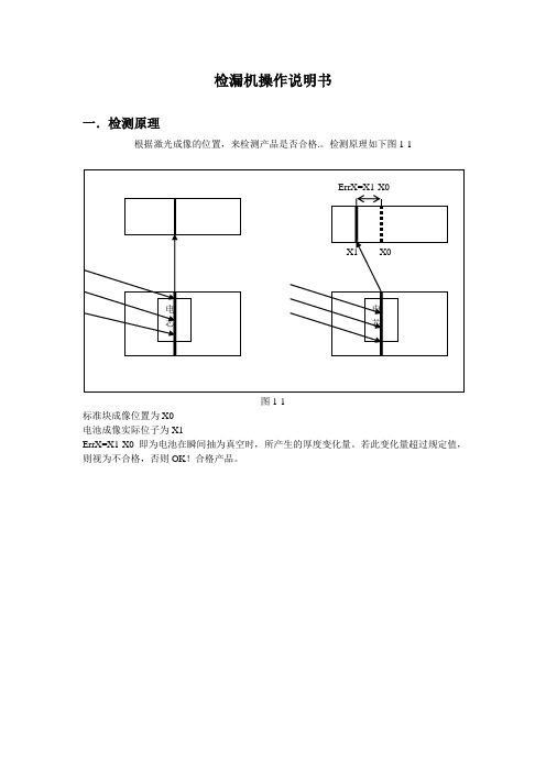
检漏机操作说明书一.检测原理根据激光成像的位置,来检测产品是否合格.。
检测原理如下图1-1图1-1标准块成像位置为X0电池成像实际位子为X1ErrX=X1-X0 即为电池在瞬间抽为真空时,所产生的厚度变化量。
若此变化量超过规定值,则视为不合格,否则OK!合格产品。
单击桌面图标,打开检漏机的测试主界面,如图2-1:图2-1由菜单栏、图像显示区、测试状态区和测试结果区四部分组成。
菜单:文件、设定、调试、标定。
文件:存储和打开图像的二进制文件。
设定:测量参数和系统参数(系统参数一般不更改)。
调试:开启相机,播放(查看分析结果)调试(相机调试)。
图像显示区:实时显示2个相机的图像,图像的放大缩小,可以通过:按下Ctrl键,同时滚动鼠标滚轮。
状态区:显示相机的状态、电磁阀的状态、真空度的状态以及设定的测试参数。
阀门2:打开和关闭缓存罐端的电磁阀。
阀门1:打开和关闭测试合端的电磁阀。
结果显示区:位置数据表示电池高度表化量,若超过规定的范围,则红色显示数据,同时红色显示NG; 否则,绿色显示,表示通过测试,是合格产品。
同时下面绿色显示OK。
曲线区为:真空度值以及电芯高度变化状况。
3.1打开数据若想查看或分析某次存储的结果,单击菜单“文件”->“打开两个相机测试二进制文件…”弹出对话框,弹出对话框,如图3-1图3-13.2保存数据在测试结束后,若想保存本次测试结果,单击菜单“文件”->“保存两个相机测试二进制文件…”,弹出对话框,如图3-2图3-23.3设定测量参数需要更改测试产品类型时,需要更改测量参数,单击菜单“设定”->“设定测量参数”,弹出登录密码框,如图3-3:图3-3-1用户名:User密码为:limuser输入正确密码,就可更改测量参数参数。
弹出如图对话框(图3-3-2):图3-3-2(注:调试测量框的时候需要单击此处的[保存测量参数] 按钮。
)直接更改参数,然后单击[保存测量参数] 按钮。
NA1000MS发电机漏氢检测中文说明书
第四章 变送器 ....................................................................................................................20 4.1 NA-1000D 变送器介绍...........................................................................................20 4.2 变送器标定................................................................................................................20
定冷水箱等处的采样系统。
传感器探头本安防爆产品,使用安全。
不转移易爆、易燃危险气体,以免制造出新的危险场合。
3
售后服务电话:800-8836699
漏氢检测仪说明书
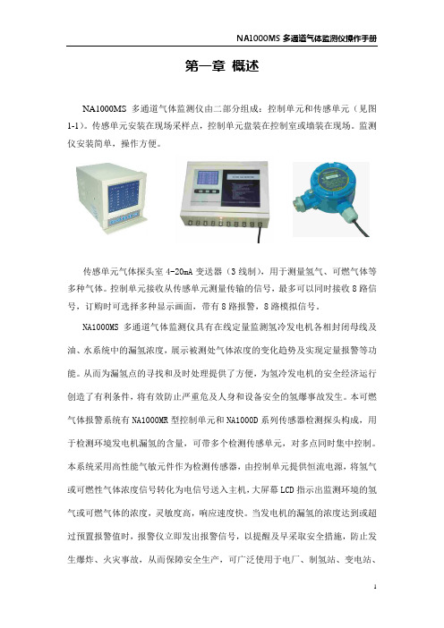
第一章概述NA1000MS 多通道气体监测仪由二部分组成:控制单元和传感单元(见图1-1)。
传感单元安装在现场采样点,控制单元盘装在控制室或墙装在现场。
监测仪安装简单,操作方便。
传感单元气体探头室4-20mA变送器(3线制),用于测量氢气、可燃气体等多种气体。
控制单元接收从传感单元测量传输的信号,最多可以同时接收8路信号,订购时可选择多种显示画面,带有8路报警,8路模拟信号。
NA1000MS多通道气体监测仪具有在线定量监测氢冷发电机各相封闭母线及油、水系统中的漏氢浓度,展示被测处气体浓度的变化趋势及实现定量报警等功能。
从而为漏氢点的寻找和及时处理提供了方便,为氢冷发电机的安全经济运行创造了有利条件,将有效防止严重危及人身和设备安全的氢爆事故发生。
本可燃气体报警系统有NA1000MR型控制单元和NA1000D系列传感器检测探头构成,用于检测环境发电机漏氢的含量,可带多个检测传感单元,对多点同时集中控制。
本系统采用高性能气敏元件作为检测传感器,由控制单元提供恒流电源,将氢气或可燃性气体浓度信号转化为电信号送入主机,大屏幕LCD指示出监测环境的氢气或可燃气体的浓度,灵敏度高,响应速度快。
当发电机的漏氢的浓度达到或超过预置报警值时,报警仪立即发出报警信号,以提醒及早采取安全措施,防止发生爆炸、火灾事故,从而保障安全生产,可广泛使用于电厂、制氢站、变电站、炼油厂、油库、液化气站、加油站、喷漆房等需防火防爆的场所进行安全检测报警。
特点1、仪表在线监测稳定,现场维护工作量小,定标周期可达半年以上。
2、仪表有LCD数值显示,有报警输出信号,以及模拟信号。
3、本监测仪的传感器仅与所测气体发生响应,不受其它种类气体的影响,选择性好,响应和恢复时间短。
4、本监测仪备有多种探头气室形式,如监测氢冷机组的,有适用于内冷水箱、冷却器回水、封闭母线和回油系统的专用采样系统。
5、探头气室的透氢膜可有效隔离油、水甚至氮气,并抗老化,在无机械应力的情况下可长期使用。
汽轮发电机漏氢检测仪LD6000
汽轮发电机漏氢检测仪LD6000德国TROTEC集团创建于1974年,是世界上最早从事气动装置密封和流量泄漏检测议的厂家之一。
便携式测漏仪LD6000便是TROTEC公司最新创作,拥有多项技术创新并申请专利。
新款便携式测漏仪LD6000是目前市场上以氢气作示踪气体及品质最优的检漏仪之一。
此款多功能检测仪广泛应用于工业过程及实验研发的测漏检测。
仪器设计符合人体工程学,便携易带,简单易学,使用方便,能能强大。
我们都只知道,氢冷发电机的氢气系统在运行中常常存在2中氢泄漏问题,一是氢气泄露至油水系统的暗漏;二是氢气泄漏至空气的明漏。
此仪器非常合适检测定位电厂发电机氢气泄漏的漏点位置。
检测仪器对暗漏一般没法很好判断,只能凭借经验丰富的人工排查处理;而明漏是发电机本体存在漏点,致使氢气向空气中泄漏,我们可以借助检测仪器精确判断泄漏点的位置并及时处理。
德国造LD6000就是一款先进的氢气泄漏定位仪器,灵敏度高,能精准定位氢气装置渗漏微漏点。
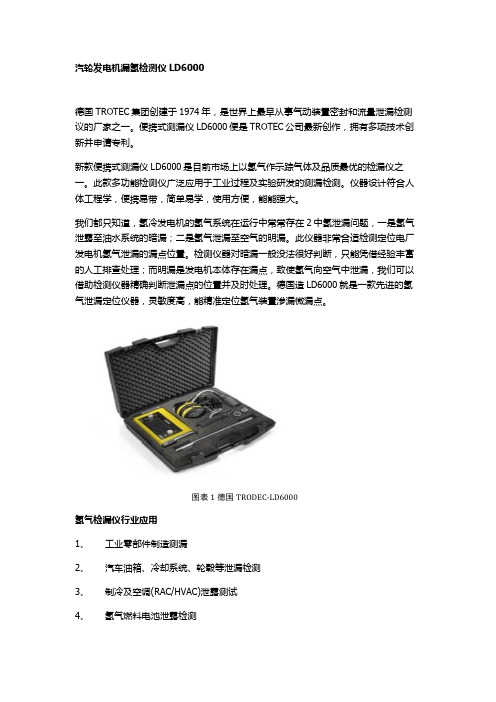
图表 1德国TRODEC-LD6000氢气检漏仪行业应用1、工业零部件制造测漏2、汽车油箱、冷却系统、轮毂等泄漏检测3、制冷及空调(RAC/HVAC)泄露测试4、氢气燃料电池泄露检测5、液体或气体输送管道泄露检测6、汽轮发电机漏氢检测7、石化泄露检测8、电子元件泄露检测9、半导体泄露检测10、平板显示及光伏测漏11、医疗及制药测漏12、产品研发及科研测漏13、航空泄露测试14、天然气工业测漏15、包装测漏16、空压机检漏17、运行中的工业氢气管网便携式测漏仪LD6000优势1、体积小,质量轻,便于携带,易于现场使用。
2、此款仪器集声学测漏和示踪气体检漏功能于一体,智能高效。
3、灵敏度高,很容易定位及定量渗漏微漏。
精确判断泄漏点位置。
·4、使用5%H2和95%N2的安全混合示踪气体,无毒且不易燃,不受其他气体或环境干扰,能确保在危险环境中的安全使用。
而且这种气体经济实惠,易于购买,相比于氦气。
泄漏检测仪操作说明书JT-1A

JT-1A地下管线泄漏探测仪用户操作手册扬州捷通供水技术设备有限公司目录1.前言 (1)1.1概述 (2)1.2注意事项 (2)1.2.1警告事项 (3)1.2.2注意事项 (3)1.3技术参数 (4)1.4技术术语 (5)1.4.1滤波器 (5)1.4.2陷波器 (5)1.4.3最小值 (5)1.4.4水平柱状条 (6)1.4.5模式旋钮 (6)2.仪器组成 (7)2.1仪器部件组成 (7)2.2硬件组成部件 (8)2.2.1主机 (8)2.2.2控制手柄 (11)2.2.3传感器 (12)2.2.4耳机 (13)2.2.5电池组与充电器 (14)3.使用检测仪 (15)3.1仪器安装 (15)3.2使用前检查 (16)3.3开机流程 (17)3.4开机页面 (18)3.5等待页面 (18)3.6检测页面 (19)4.泄漏探测方法 (20)4.1沿管线探测 (20)4.2定位泄漏点 (22)4.3频散对泄漏定位的影响 (23)5.疑难解答 (24)1.前言非常感谢您选择使用JT-1A地下管线泄漏探测仪。
本说明书详细阐述了如何操作和使用JT-1A地下管线泄漏探测仪。
本说明书详细描述了JT-1A地下管线泄漏探测仪的组成、功能、操作方式、注意事项以及使用探测仪进行埋地管道泄漏探测的方法。
请您在操作或使用本仪器之前务必仔细阅读并完全理解本操作说明书中的内容。
如果您对JT-1A地下管线泄漏探测仪在操作和使用上有任何疑问,可随时拨打我公司电话(0514)87236231,我们会向您提供及时而热诚的技术支持和服务。
谢谢合作!请您妥善保管本说明书以便需要时使用,如有说明书遗失或损坏,请您立即联系我公司。
1.1概述JT-1A地下管线泄漏探测仪通过传感器拾取地下压力管道破损泄漏所产生的振动信号来准确定位泄漏点的位置。
本泄漏检测仪配置了适应不同检测环境的传感器,从而能有效地实现泄漏点的检测与定位。
通过选择该检测仪器中配置的16组频段组合中的任何一组频段来检测泄漏信号,以满足不同材质/管径管道、不同工作地段(埋层介质)的泄漏检测需要。
漏氢检测FJR-IIA装置说明书1

FJR—IIA型发电机绝缘过热监测装置说明书华北电力科学研究院有限责任公司北京华科兴盛电力工程技术有限公司二○○六年再版华北电力科学研究院有限责任公司北京华科兴盛电力工程技术有限公司地址:北京市西城区复外大街地藏庵南巷1号邮编:100045电话:(010)68033998(010)88072032传真:(010)68033232FJ R-ⅡA型发电机绝缘过热监测装置说明书FJ R-ⅡA型发电机绝缘过热监测装置一、前言FJR―ⅡA型发电机绝缘过热监测装置,是应用九十年代高新技术对FJR-Ⅱ型装置进行技术改进研制的智能型装置。
它是国内领先水平的发电机在线监测装置,也是华北电力科学研究院有限责任公司的高新技术专利产品。
该装置适用于不同容量的空冷、氢冷和水冷发电机组,在线监测发电机内部绝缘过热事故隐患,它是早期诊断发电机绝缘过热故障的一种较灵敏装置。
通过故障采样,经过质谱分析,能够区分发电机定子线棒、铁芯和转子绕组等不同部位的绝缘过热故障。
FJR-ⅡA型装置是智能型仪器,灵敏度高,抗干扰能力强,能自动故障判别、自动报警、自动追踪、自动打印和智能储存。
在现场调试简单,维护方便,运行安全。
FJR-ⅡA型同FJR-Ⅱ型的区别在于FJR-ⅡA型装置为同功能一体化,不设小机箱,减少安装工作量。
二、主要技术性能1.工作条件环境温度: 0~50℃相对湿度:≤85%电源: AC 220V 50Hz容量: 100VA使用方式:连续运行安装位置:在6米平台发电机下部2.主要技术指标工作压力:满足5.3×10⁵ Pa为额定氢压及以下的汽轮发电机组检测流量:2~6L/min取样流量:5~10 L/min取样容积:100L以上零点漂移:正常运行24小时,零点漂移不大于表计全量程的±3%电流指示:正常运行时100~110%报警整定值:75%±1%检测灵敏度:机内绝缘局部过热面积(包括绝缘漆退色)为12㎝2 时,电流下降百分率不小于30%绝缘水平:电源输入回路对外壳的绝缘电阻>500MΩ交流耐压:1500V记录纸更换周期:每年1~2次3.性能及特点该装置具有适应性强,液晶显示,智能化程度高的特色。
- 1、下载文档前请自行甄别文档内容的完整性,平台不提供额外的编辑、内容补充、找答案等附加服务。
- 2、"仅部分预览"的文档,不可在线预览部分如存在完整性等问题,可反馈申请退款(可完整预览的文档不适用该条件!)。
- 3、如文档侵犯您的权益,请联系客服反馈,我们会尽快为您处理(人工客服工作时间:9:00-18:30)。
第一章概述NA1000MS 多通道气体监测仪由二部分组成:控制单元和传感单元(见图1-1)。
传感单元安装在现场采样点,控制单元盘装在控制室或墙装在现场。
监测仪安装简单,操作方便。
传感单元气体探头室4-20mA变送器(3线制),用于测量氢气、可燃气体等多种气体。
控制单元接收从传感单元测量传输的信号,最多可以同时接收8路信号,订购时可选择多种显示画面,带有8路报警,8路模拟信号。
NA1000MS多通道气体监测仪具有在线定量监测氢冷发电机各相封闭母线及油、水系统中的漏氢浓度,展示被测处气体浓度的变化趋势及实现定量报警等功能。
从而为漏氢点的寻找和及时处理提供了方便,为氢冷发电机的安全经济运行创造了有利条件,将有效防止严重危及人身和设备安全的氢爆事故发生。
本可燃气体报警系统有NA1000MR型控制单元和NA1000D系列传感器检测探头构成,用于检测环境发电机漏氢的含量,可带多个检测传感单元,对多点同时集中控制。
本系统采用高性能气敏元件作为检测传感器,由控制单元提供恒流电源,将氢气或可燃性气体浓度信号转化为电信号送入主机,大屏幕LCD指示出监测环境的氢气或可燃气体的浓度,灵敏度高,响应速度快。
当发电机的漏氢的浓度达到或超过预置报警值时,报警仪立即发出报警信号,以提醒及早采取安全措施,防止发生爆炸、火灾事故,从而保障安全生产,可广泛使用于电厂、制氢站、变电站、炼油厂、油库、液化气站、加油站、喷漆房等需防火防爆的场所进行安全检测报警。
特点1、仪表在线监测稳定,现场维护工作量小,定标周期可达半年以上。
2、仪表有LCD数值显示,有报警输出信号,以及模拟信号。
3、本监测仪的传感器仅与所测气体发生响应,不受其它种类气体的影响,选择性好,响应和恢复时间短。
4、本监测仪备有多种探头气室形式,如监测氢冷机组的,有适用于内冷水箱、冷却器回水、封闭母线和回油系统的专用采样系统。
5、探头气室的透氢膜可有效隔离油、水甚至氮气,并抗老化,在无机械应力的情况下可长期使用。
6、不转移易爆、易燃危险气体,以免制造出新的危险场合。
7、本监测装置结构紧凑、安装简便、仪表除直接指示测点氢气浓度。
第二章技术指标2.0 NA1000MR型控制单元测量范围:0~100%LEL精度:±5%(F.S)报警点:可编辑指示方式:点阵式LCD屏检测通道:1~8路(任选)工作方式:现场固定安装,连续工作工作环境温度:-20℃~50℃工作环境湿度:〈90%RH工作电源:AC220V±10% 50Hz传感器::MAX 1W/路接点输出:常开无源触点,AC220V 0.5A模拟输出:4~20mA外型尺寸:墙装:400mm×300mm×120mm(长×宽×高)安装方式:盘装仪表用两个仪表卡子固定在仪表柜上,安装开孔尺寸高137mm,宽137mm,仪表箱长(包括接线端子)236mm。
2.1 NA1000D系列传感器适用气体:氢气、天然气(甲烷)、液化气(异丁烷、丙烷)、煤气(氢气)、烷类、炔类、烯类、可燃性气体及酒精、丙酮、甲苯、甲醇、汽油、油漆稀料等液体蒸汽检测范围:0~100%LEL采样方式:自然扩散环境温度:-10~60℃环境湿度:〈98%RH防爆等级:ia ⅡCT 3电源:DC 24V 60mA输出:三线4-20mA安装方式:探头安装在测点处,安装部位:封闭母线、内冷水箱、冷却器回水管、回油管汽励侧、缸盖汽励侧等处。
第三章安装3.0安装注意事项1、内冷水箱及回油管的下法兰,冷却器回水管取样系统均要在现场配接。
2、传感单元探头气室外部贴有标签,指示这处气室的安装部位。
安装气室时,一定要按标签指示就位。
3、回油管气室、冷却器回水管气室、及内冷水箱与下法兰之间均要有耐油密封圈。
4、冷却器回水管漏氢测点处除探头气室外,厂家只提供针型阀和取样罐及罐卡子,余下现场制作。
冷却器回水管针型阀开始处于完全关闭状态,开机后等回水管中的水流正常后,慢慢开启针型阀门使出水管口有很少量水滴出即可。
5、下法兰和气室的安装位置应考虑今后维护时容易操作。
6、控制单元内与外部接线全部接完后,再把气室传感器插头连接上。
7、气室中的氢敏传感器必须拿出时,要注意防油和水的沾污。
8、控制单元本身及电缆屏蔽线均要良好接地。
良好的接地关系到整个装置的在线使用寿命。
9、内冷水箱应通过三通连到内冷水箱的排气管上,没有这个条件时,也可连到其它出口上,以不防碍内冷水箱正常工作为宜。
10、传感单元探头气室的上下进出气口,内部均装有氢油水高分子分离膜,外来的硬尖物碰撞会给它造成永久性的损害,进而造成氢敏传感器无法使用。
以上安装工作完成后,请用户通知厂家人员到现场与安装公司一起做通电前总检查和动态调试。
3.1 安装NA1000MR型控制单元(1)选择无可燃性气体、腐蚀性气体、油烟、尘埃并防雨的安全场所安装控制单元。
(2)控制单元可同时接入的传感单元数量为:1-8路,同时可提供8报警信号和8路模拟信号;每测点的传感单元需一根与控制单元连接的3芯屏蔽电缆。
3.2 安装NA1000D系列传感器3.2.1传感单元电气连接用附带的安装架将本机牢固安装于需检测场所,旋开传感单元上盖,按图4的说明接入电源及信号线,安装好上盖,打开远端控制单元,传感单元即可正常工作。
(1)将信号穿入传感单元接线孔,将传感单元牢固安装于布好专用电缆1/2寸无缝钢质护套管上,密封接口。
3.2.2 传感单元检测点的安装(1)封闭母线上的测点:建议气室和封母箱体监测点的安装位置安排在箱体外侧,便于探头调零定标时拿取方便安全,见图7或图11所示。
由于透氢膜的作用,探头接入后不会造成封母箱体的泄压。
(2)内冷水箱的测点:内冷水箱的监测点安装在内冷水箱顶部排气管处,连接示意见图9或图12所示。
将厂家提供的检测单元(包括传感单元和专用采样系统)以螺接或焊接的方式连接到内冷水箱排气口。
由于透氢膜的作用,探头接入后不会造成其他气体(如:CO2 、N2等)外泄。
(3)回油管道上的测点:建议安装在汽、励端回油管水平段上,焊上厂家提供的采样室,此采样室端面安装方向要垂直向上。
回油管安装位置见图8所示,安装点应考虑以后气室探头调零定标时拿取方便,及不易被其它工种操作碰损处。
(4)冷却器回水管测点:使用厂家提供的前端带有45℃斜面的取样管连同取样罐安装在6米层的回水管上(见图13和图14),在取样罐和这段水管之间焊上厂家提供的不锈钢针阀。
焊接和清洗后方能螺接探头气室。
3.3 测点的传感单元与控制单元接线:从控制单元到测点的连接电缆,用户需为每测点铺一根多股线结构的3芯屏蔽电缆,电缆单芯截面大于0.2平方毫米。
如果电缆超过3芯,多余的芯线要和屏蔽同时接仪柜地。
用户电缆和厂家电缆之间的连接可直接接入传感单元盒内的接线端子。
接线端子上要有标注。
第四章电气连接1、打开NA1000MS多通道气体监测仪控制单元的前盖,按照图4和图5的电气连接将各测点的传感单元信号线及输出控制线、电源线接入相应端子并标注标号,连接完毕,检查无误后合上控制单元前盖。
2、接通控制单元的交流220V电源,控制单元即进行自检,显示屏上应有相应的数值显示。
3、注:(1)如果是壁挂式控制单元,则供电方式是:一路AC220V,50Hz电源;(2)如果是盘装式控制单元,则供电方式是:一路AC220V,50Hz电源和一路DC24V,1.5A的开关电源第五章操作5.0 NA1000MR型控制单元(1)接通交流220V电源本机进行自检,约3秒后进入正常监控状态。
(2)本机连接的传感单元处于无可燃气体的洁净空气中,检查对应监控主机显示应为00±5%(F.S),否则应进行标定调整。
(3)使控制单元连接的传感器处于配置好的浓度为50%LEL的相应气体中,检查对应控制单元通道显示应为50%±5%(F.S),否则应进行标定调整。
(4)使控制单元连接的传感单元处于配置好的浓度为预设报警点的气体中,检查对应控制单元通道显示应为相应值±5%(F.S),并触发相应通道警报,否则应进行报警调整。
(5)完成以上步骤,即可投入正常使用。
5.0.1监测仪功能盘装面板显示为例:显示屏按键按键介绍如下图:键盘的各个按键在实时显示画面和组态画面具有不同的功能。
:左方向键;向左移动光标,选择参数;:右方向键;向右移动光标,选择参数;:上方向键;向上移动光标,选择参数;变更设定时,用于减少数值.:下方向键;向下移动光标,选择参数;变更设定时,用于增加数值:确认键;进入菜单键,参数更改确认键5.0.2 设置1:组态设置显示画面:操作:上下左右方向键分别为方向键,在相应选项按确认键可进入相应菜单,各菜单的功能说明在随后有详细说明。
2:系统组态显示画面:用来设置系统环境。
操作: 按左右方向键分别用来更换要设置的位数,按下方向键,数值减小,按上方向键数值增加,按确认键确认并保存;3:画面组态画面组态设置操作:通过按上下方向键将光标移动到所选择的显示画面,在按ENT键来选中,当所选的画面的背景变亮,且右侧有圆点出现,表明已经选中,例如:此时的画面,表明大数显示被选中;再通过下方向键移动光标到“确认”,按确认键返回到测量模式时,则此画面即为大数显示。
A:波形显示画面显示如图当前通道设定的报警值操作:按上下方向键来选择所要查看的通道及相应通道的数值和波形;在这个画面可连续且同时监测到报警的通道。
B:棒图显示显示画面如图所示:操作:按左右方向键移动,选择所要查看的通道及测量值,每一画面最多能同时显示8个通道,如果多出则使用上下方向键来选择所要的通道及数值。
报警状态可在每个画面中同时显示。
C:表格显示显示画面如图所示:操作:全屏显示所有通道的测量值和所有通道的报警状态,无需进行按键操作。
D操作:通过上下方向键选择所要查看的通道及数值, E :追忆显示 显示如图:操作:按上下方向键选择所要查询的历史记录,可以设定选择的所要查询的时间段。
4.变送组态画面显示如下:操作:设定通道对应的模拟输出(最多为8路模拟输出),出厂设定为一一对应,即CH1对应OUT1;如果需要更改,可以通过上下方向键选择所有输出的通道,按确认键确认后,再选择输出的编号,正确选择完毕,按下键将光标移动到退出位置,按ENT键退出变送设置。
5.通讯组态画面显示:操作:此功能仅为工厂校准使用;无任何按键操作,此组态出厂已经设定完毕,无需用户进入和设置。
6.报警组态画面显示:功能介绍:(1)可以进行报警查询(2)更改报警设置;(3)清除报警设置操作:使用上下方向键移动光标到选择所要设置的通道报警值,按ENT键确认,再使用上下方向键更改数值;通过上下方向键移动光标选择报警查询或报警清除,按ENT键查看报警值和全部清除报警存储值。