丹佛斯变频器modbus通讯
丹佛斯变频器PROFIBUS通讯配置
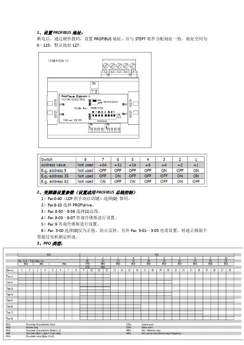
1、设置PROFIBUS地址:断电后,通过硬件拨码,设置PROFIBUS地址,应与STEP7软件分配地址一致,地址空间为0~125,默认地址127。
2、变频器设置参数(设置成用PROFIBUS总线控制)1)Par.0-40(LCP的手动启动键)选择[0] 禁用。
2)Par.8-10选择PROFIdrive。
3)Par. 8-50~8-56选择[1]总线。
4)Par. 8-03~8-07咨询丹佛斯进行设置。
5)Par. 9咨询丹佛斯进行设置。
6)Par. 3-00选择[0]仅为正值,防止反转。
另外Par. 3-01~3-03也需设置,转速正极限不要超过电机额定转速。
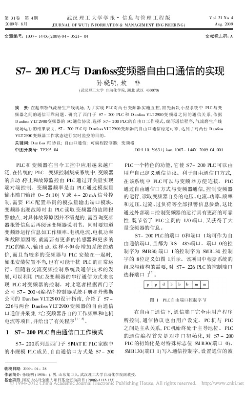
3、PPO类型:见上表,总共有PPO Type 1~8共8种模式。
PPO types 3、4、6、7和8用于非循环参数访问,只能访问PCD(过程控制数据),但是不能对PCV(变频器参数特征值)进行访问。
选择上述5种模式,PLC送出过程控制数据,变频器响应后返回过程状态数据。
对于过程控制数据,PCD头4个字节(图中1、2)由CTW (控制字)和MRV(主要参考值――速度)组成,用来控制电机起停以及速度给定。
下4个字节(图中3、4)写Par. 9-15[1]中设置的可以写的参数;对于状态数据,PCD头4个字节(图中1、2)由STW(状态字)和MAV(主要实际值――速度)组成,用来反应电机运行状态以及速度反馈值。
下4个字节(图中3、4)写Par. 9-16[1]中设置的可以读的参数。
后续字节为Par. 9-23中设置的参数。
PPO types 1、2、5可以对PCV(变频器参数特征值)和PCD(过程控制数据)进行读写。
所有PPO types都可以选择成Word consistent(只有PCV数据是连续的,不需要调用SFC14,15)和Module consistent(PCD,PCV数据是连续的,都有调用SFC14,15)。
4、CTW(控制字)/ STW(状态字):根据Par.8-10设置的不同可以选择PROFIdrive或者FC结构。
丹佛斯变频器的串行通讯

应用实例Note.31 2001.10 丹佛斯VLT变频器的串行通讯王孟贤丹佛斯有限公司北京代表处丹佛斯VLT系列变频调速器对串行通讯技术的成熟支持是用户所公认的供献丹佛斯VLT变频器所支持的串行通讯技术包括标准RS485, 及包括PROFIBUS DEVICENET LONWORKS 等在内的各种现场总线方式其中RS485通讯方式为用户提供了无需附加费用的最为廉价实用的串行通讯方式用户只需按照丹佛斯VLT变频器规定的通讯数据结构控制字和状态字格式发送数据即可实现与VLT的通讯VLT为用户提供了两种控制字和状态字格式标准即丹佛斯VLT标准FC Drvie 和Profibus 标准Profidrive前者为用户提供了更多的与VLT有关的控制信息和状态信息.后者为国际标准VLT变频器的串行通讯为异步半双工方式使用字节奇偶校验和块传送异或校验方法由于VLT变频器提供了开放的通讯协议所以PLC 与VLT 能否成功的实现通讯取决于用户使用的PLC是否具有标准的通讯能力丹佛斯VLT变频器与PLC的通讯应用有着众多的成功范例本例所介绍的内容是丹佛斯VLT变频与Misubish PLC 通过RS485接口实现的串行通讯过程其具体介绍如下:一系统接线VLT2800 VLT5000 VLT6000注: 端子68和69是VLT各系列变频器的标准RS485的专用接二VLT 参数设置 参数P500设定站址 参数P512FC 协议三PLC 程序举例例1PLC 向VLT 发布运行频率给定值25HZ 和0输出其通讯数据结构如下 stx lge adr pcdlpdc2bcc 020604 047C20005825HZ 运行的通讯数据stx lge adr pcdl pdc2bcc 02060404 7C000078VLT 零输出时的通讯数据在上述数据结构中stx=起始字节=02H lge=数据长度该字节以后所有字节数之和adr=被叫站站址pcd1,2=数据处理字节bcc=校验字节该字节之前的所有字节之异或值表中字节为十六进制数上述数据的PLC 发送程序梯形图见附表1stx lgeadrpkeindPwe,high Pwe,lowpcd1pcd2bcc 02 0E 01 B0 CA 00 00 00 00 03 E8 00 00 00 00 CPLC 的发送程序梯形图见附表2SET M8161MOV H0C87 MOV H0002 MOV H0006 MOV H0004 MOV H0004 MOV H007C MOV H0020 MOV H0000MOV H0058RS D200 K8 D500SET M81220 M8000X000X001349RST Y000( Y000 )M812361MOV H0C87 MOV H0002 MOV H0006 MOV H0004 MOV H0004 MOV H007C MOV H0000 MOV H0000MOV H007864X002RS D200 K8 D500SET M8122RST Y000( Y000 )110122X003M8123附表1.SET M8161MOV H0C87 MOV H0002 MOV H000E MOV H0001 MOV H00E0 MOV H00CA MOV H0000 MOV H0000 MOV H0000 0 附表2 M80023MOV H0000 MOV H0003 MOV H00E8 MOV H0000 MOV H0000 MOV H0000MOV H0000MOV H00CCRS D200 K16 D500SET M8122RST Y000( Y000 )X000 M812389101注: 本文梯形图程序由丹佛斯有限公司上海代表处 付锐 先生提供.。
S7_200PLC与Danfoss变频器自由口通信的实现_孙晓明
第31卷 第4期2009年8月武汉理工大学学报 信息与管理工程版J OURNAL OF WUT (I N FORM AT I ON &MANAGE M ENT E NG I NEER I NG )V o.l 31N o .4A ug.2009文章编号:1007-144X (2009)04-0521-04文献标志码:AS7-200PLC 与Danfoss 变频器自由口通信的实现孙晓明,敖 非(武汉理工大学自动化学院,湖北武汉430070)摘 要:在超细粉气流磨生产线现场,为了实现PLC 对两台变频器实施监控,需先解决小型系统中PLC 与变频器之间的通信可靠问题。
研究了西门子S7-200PLC 和D anfoss VLT 2900变频器之间的通信关系,依据D anfoss V LT 2900变频器的FC 通信协议,选择S7-200PLC 的自由口工作模式,编写通信程序,气流磨生产线现场运行的结果表明,S7-200PLC 与D anfoss VLT 2900变频器的自由口通信稳定可靠,达到了对两台D anfoss VLT 2900变频器工作状态进行实时监控的目的。
关键词:D an f o ss FC 协议;自由口通信;可编程控制器;变频器中图分类号:TP393.04DO I :10.3963/.j issn .1007-144X.2009.04.001收稿日期:2009-01-28.作者简介:孙晓明(1956-),男,山东龙口人,武汉理工大学自动化学院副教授.基金项目:国家863计划重大项目基金资助项目(2006AA11A133).PLC 和变频器在当今工控中应用越来越广泛,在传统的PLC -变频控制集成系统中,变频器的启动/停止和故障监控由PLC 通过开关量实现端对端控制。
变频器频率是由PLC 通过模拟量输出端口输出0~5(10)V 或4~20mA 信号控制,需要PLC 配置昂贵的模拟量输出端口模块。
S7-300与丹佛斯变频器Profibus-DP通信

15
3、西门子S7-300PLC与丹佛斯FC300通讯程序编写 我们接着来学习如何编写西门子PLC程序控 制丹佛斯变频器的
16
3、西门子S7-300PLC与丹佛斯FC300通讯程序编写
3.1、对PCD (过程数据)的读写 :a.在Step7 中对PCD (过程数据)读写参 数时调用SFC14和SFC15。b. SFC14(“DPRD_DAT”)用于读Profibus 从站 (FC300)的数据。c. SFC15(“DPWR_DAT”)用于将数据写入Profibus 从站
14
2、丹佛斯FC300的profibus通讯格式
2.14 、丹佛斯FC300参数设置:要使变频器能够用PLC通过Profibus来控制,变 频器也需要一定的参数设置才能实现,变频器初始化后需要注意以下参数设置:
P801 命令源: 数字或者控制字 (或者仅仅控制字) P810 控制字格式: FC或者Profidrive P918 站号: 3 (必需与硬件组态时保持一致 。
1
1、西门子S7-300PLC与丹佛斯FC300通讯组态过程
硬件要求:1.S7-300 CPU313-2DP、2.FC300、3.PROFIBUS-DP 接口模块,用于安装在FC300上,使之成为PROFIBUS-DP从站。 1.1、建立文件:打开SIMATIC MANAGER, 通过FILE菜单选择NEW新建一个项目, 在NAME栏中输入项目名称,将其命名为TEST,在下方的Storage Location中设 置其存储位置。
现采用4PCV,2PCD ;FC300地址为3。
8
1、西门子S7-300PLC与丹佛斯FC300通讯硬件组态 练习:尝试设置PLC与丹佛斯变频器硬件组态并下载。
丹佛斯变频器FC串口通讯协议介绍
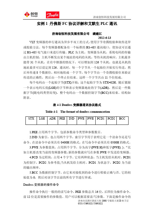
实例1 丹佛斯FC协议详解和艾默生PLC通讯济南创恒科技发展有限公司满建江2012-6-13 VLT变频器的串行通讯为异步半双工的方式,使用字节奇偶校验和块传送异或校验方法。
每个变频器都配备有一个标准的RS-485通讯端口,使协议可以通过RS-485电气接口来进行传输。
PLC为主机,变频器为从机,系统电码的传输由主机控制,主机不断发出某个地址的电码给从机,等待从机的响应。
主机最多能带31个从机,在有中继器的情况下,可以增加到126个从机,也就是从机的地址最多可以设定到126。
通讯时,每一个字节从一个起始位开始实行传送,然后再传递8个数据位,相应地组成一个字节,每个字节由一个奇偶校验位来验证传送的正确性,然后由一个终止位结束。
这样一个字节共由11个位组成。
每个电码由一个起始字节(STX)开始,这个起始字节为STX=02H。
随后紧跟一个表示电码长度(LGE)的字节和表示变频器地址的字节(ADR)。
然后是一些数据字节(随电码类型而变)。
整个电码由一个数据控制字节(BCC)来结束。
结构如附表。
表4-1 Danfoss变频器通讯协议格式Table 4-1 The format of danfoss communcation1.PKE占用两个字节,包括参数命令类型和参数数目。
2.IND为索引,也占用两个字节,索引字节用于表明它是一个读命令还是写命令。
在读命令中必须具有0400H的格式,在写命令中必须具有0500H的格式。
3.PWE为参数值块。
占用四个字节,分为高字(PWE H)和低字(PWE). )。
“比如主机要改变当前的变频器参数,新的参数就应写在参数PWE中发送给变频器。
4.PCD为过程块,占用4个字节。
它有两种状态,当主机发给从机时,PCD1为控制字,PCD2为参考值;当从机发给主机时,PCD1为状态字,PCD2为当前的输出频率。
5.BCC为数据控制字节。
由它来对接收到的命令进行检验正确与否。
它的初始值为0,然后对该字节以前的所有字节进行异或。
丹佛斯变频器modbus通讯
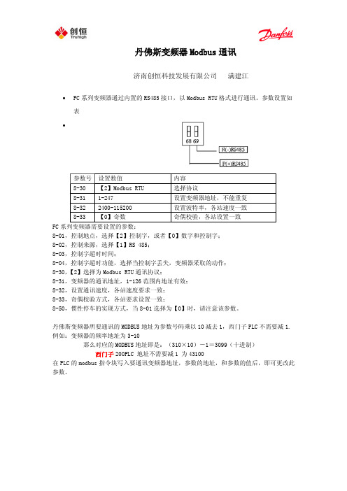
丹佛斯变频器Modbus通讯济南创恒科技发展有限公司满建江∙FC系列变频器通过内置的RS485接口,以Modbus RTU格式进行通讯。
参数设置如表∙FC系列变频器需要设置的参数:8-01,控制地点,选择【2】控制字,或者【0】数字和控制字;8-02,控制来源,选择【1】RS 485;8-03,控制字超时时间;8-04,控制字超时功能,选择当控制字丢失,变频器采取的动作;8-30,【2】选择为Modbus RTU通讯协议;8-31,变频器的通讯地址,1-126范围内地址有效;8-32,设置通讯速度,各站速度要求一致;8-33,奇偶校验方式,各站要求设置一致;8-50,惯性停车的实现方式,当8-01选择为【0】时,请注意该参数。
丹佛斯变频器所要通讯的MODBUS地址为参数号码乘以10减去1,西门子PLC不需要减1. 例如:变频器的频率地址为3-10那么对应的MODBUS地址即是:(310×10)-1=3099(十进制)西门子200PLC 地址不需要减1 为43100在PLC的modbus指令块写入要通讯变频器地址,参数的地址,和参数的值后,即可更改此参数。
∙电报结构(十六进制)∙地址字段包含8位数据,有效的地址范围为0-247(十进制),0为广播模式;1-247对相应地址的从站进行寻址。
功能字段包含8位数据,有效地代码范围为1-FF,功能字段用于在主站和从站之间发送消息。
当从主站向从站发送时,功能字段为主站的控制字;当从从站向主站传送时,功能字段为从站的状态字。
∙数据字段,是由几组字节两个十六进制数字(00至FF)构成,根据不同的功能代码,数据字段包含的位长、作用不一,针对常用的功能代码,举例如下:∙1、功能代码=1,读取线圈状态∙ 2、功能代码=5,写入单个线圈数值∙ 3、功能代码=F,写入多个线圈数值∙线圈及位的意义。
地址0-31为主站写入用控制位,32-63为从站返回的状态位,如下表所示:∙例如,使电机启动并运转在50%*最大参考值的报文如下∙其中位的个数为 20H=32个位,也就是从00地址起始到31为止的位;字节数,是指写入数值为4个字节;写入数值 047C 对应00-16位,在传送时低位在前,因此为7C 04;2000 对应16-31位,50%*最大参考值,在传送时低位在前,因此为00 20;对于停止,应发043C代码4、功能代码=3,读取保持寄存器状态,保存寄存器保持2字节(即16位)∙ 5、功能代码=6,写入单个寄存器∙ 6、功能代码=10,写入多个寄存器数值∙寄存器列表:∙例如,当要读取3-41,加速时间时,需要写的报文:∙计算参数3-41的地址 3-41 → 341*10-1=3409 → D51(十六进制);保持寄存器状态都为双字节,因此在字个数位置应该为 2 ;正常情况下,变频器返回的报文为,∙012C 为读出的加速度时间,转换成十进制并考虑到控制单位,得到加速时间为3秒。
丹佛斯变频器PROFIBUS通讯配置
1、设置PROFIBUS地址:断电后,通过硬件拨码,设置PROFIBUS地址,应与STEP7软件分配地址一致,地址空间为0~125,默认地址127。
2、变频器设置参数(设置成用PROFIBUS总线控制)1)Par.0-40(LCP的手动启动键)选择[0] 禁用。
2)Par.8-10选择PROFIdrive。
3)Par. 8-50~8-56选择[1]总线。
4)Par. 8-03~8-07咨询丹佛斯进行设置。
5)Par. 9咨询丹佛斯进行设置。
6)Par. 3-00选择[0]仅为正值,防止反转。
另外Par. 3-01~3-03也需设置,转速正极限不要超过电机额定转速。
3、PPO类型:见上表,总共有PPO Type 1~8共8种模式。
PPO types 3、4、6、7和8用于非循环参数访问,只能访问PCD(过程控制数据),但是不能对PCV(变频器参数特征值)进行访问。
选择上述5种模式,PLC送出过程控制数据,变频器响应后返回过程状态数据。
对于过程控制数据,PCD头4个字节(图中1、2)由CTW (控制字)和MRV(主要参考值――速度)组成,用来控制电机起停以及速度给定。
下4个字节(图中3、4)写Par. 9-15[1]中设置的可以写的参数;对于状态数据,PCD头4个字节(图中1、2)由STW(状态字)和MAV(主要实际值――速度)组成,用来反应电机运行状态以及速度反馈值。
下4个字节(图中3、4)写Par. 9-16[1]中设置的可以读的参数。
后续字节为Par. 9-23中设置的参数。
PPO types 1、2、5可以对PCV(变频器参数特征值)和PCD(过程控制数据)进行读写。
所有PPO types都可以选择成Word consistent(只有PCV数据是连续的,不需要调用SFC14,15)和Module consistent(PCD,PCV数据是连续的,都有调用SFC14,15)。
4、CTW(控制字)/ STW(状态字):根据Par.8-10设置的不同可以选择PROFIdrive或者FC结构。
西门子PLC与丹佛斯300型变频器通过PROFIBUS网络的组态通信

张春 杰 ( 河南中烟公 司新郑卷烟厂, 河南 新郑 4 15 ) 5 0 1
摘 要
通 过 例 证 , 细介 绍 了西 门 子 S 一 L 与 丹佛 斯 3 0型 变 频 器通 过 P OF B — P 网络 连接 的 配置 和 编 程 。 详 7P C 0 R I US D 关 键 词 : 门子 P C, 佛 斯 变 频 器 , R F S D 西 L 丹 P O 旧U — P网络 , 配置
3 2型 变 频 器 ( 卡 MC O ) 过 P OF B S— 1 网 A1 1 通 R IU DP 网络 连 接 的硬 件 组 态 、 编程 和 变 频 器 的设 置 。
1 西 门子 硬 件 组 态
1 打 开 SMA l 管 理 器 , ) I TC 点击 “ e rjc( N w Poe t新项 目) , ”输
输 入 、 出地 址 ( 节 数 ) 长度 不 一样 。 输 字 的
3 展 开 项 目名 称 , 择 “ ad r( 件 ) , 击 进 入 。 ) 选 H rwae 硬 ”双
4选择机架 、 ) 电源 和 CP , “ 3 。 U 如 图 ” 5 依 次展 开 “ R I U P / A dt n l il D v e ” ) P OFB S D … ‘ d i a Fed e i s / i o c “ r e ” “ a fs … F 0 2 0 3 0 , 选 中 “ C1 0 2 0 D i s / D no s /‘C1 / 0 / 0 ” v 0 F /0 / 0
2 右击项 目名称 , ) 插入新对象 “n etN w Obic”选择 I r e j t, s e
“ MATl 4 0 Stt n” 如 “ 2” SI C 0 a i , 图 o 。
丹佛斯变频器MODBUSRTU的通讯

关于丹佛斯变频器MODBUS RTU的通讯发布时间: 2008-11-18 12:03:40 被阅览数: 476 次一:MODBUS? RTU规约概术??? MODBUS规约是MODICOM公司开发的一个为很多厂商支持的开放规约MODBUS 协议是应用于电子控制器上的一种通用语言。
通过此协议,控制器相互之间、控制器经由网络(例如以太网)和其它设备之间可以通信。
它已经成为一通用工业标准。
有了它,不同厂商生产的控制设备可以连成工业网络,进行集中监控。
此协议定义了一个控制器能认识使用的消息结构,而不管它们是经过何种网络进行通信的。
它描述了控制器请求访问其它设备的过程,如果回应来自其它设备的请求,以及怎样侦测错误并记录。
它制定了消息域格局和内容的公共格式。
???? 二:丹佛斯MODBUS RTU概念????? DANFOSS 变频器在自动化领域中有着大量的应用,作为变频器专业供应商,DANFOSS 一直把提高产品的通信应用水平作为其重点工作之一。
基于MODBUS RTU协议,DANFOSS 开发了相应的控制集成卡,通过这种集成卡DANFOSS变频器可以以MODBUS RTU 协议方便与SCADA和HMI等设备集成在一起。
????????? DANFOSS? VLT2800或VLT5000(已停产)系列变频器MODBUS RTU通讯与FC300系列变频器的通讯类似?三:S7-200、台达PLC与丹佛斯变频器接线:?S7-200 DSUB9??????? DANFOSS???? 3----+------------------68???? 8------------------------69?台达PLC正信号+---------------------68负信号-----------------------69?四:丹佛斯变频器的参数设置?1.VLT5000(已停产)或VLT2800变频器相关通讯参数设置:561#---------2----RTU协议500#---------1----485地址为1???????????501#---------5----9600570#---------0----1停止位,EVEN校验其他参数使用初始化参数?2.FC300或FC51变频器相关通讯参数设置:8-30-----1----RTU协议8-3地址8-32----------波特率8-33----------1停止位,EVEN校验??五:PLC的程序例子如果该变频器加了MCO305同步卡或PROFIBUS卡,此通讯功能被占用。
丹佛斯变频器Profibus通讯

丹佛斯变频器profibus通讯济南创恒科技发展有限公司满建江第一步:导入FC300的GSD文件第二步:将FC300拉入总线上,并设置总线地址,参数等。
第三步:配置参数过程数据对象(PPO)的类型,可以选择PP0Type 4 word consistent PCD. 这是软件会自动分配我们所使用的寄存器的地址。
由Master站传输给变频器(VLT)的PPO 4CTW: 控制字占用第1、2字节;MRV: 速度设定值占用第3、4字节;PCD: 过程数据(4个) 占用第5~第12字节主要用来修改变频器参数(即参数9-15数组2-9所设定的参数);•由变频器(VLT)反馈给Master站的PPO 4STW: 状态字占用第1、2字节;MAV: 速度反馈值占用第3、4字节;PCD: 过程数据(4个) 占用第5~第12字节主要用来反馈变频器状态信息(即参数9-16数组2-9所设定的参数);软件配置的地址是从STW(CTW)开始的,例如软件配置从512-523地址。
则512-513是STW(CTW)的地址,514-515是MAV(MRV)的地址。
516-517是PCD1的地址-----等控制字采用danfoss的FC协议例:16#047C为启动变频,16#043C为停车。
变频器的频率设定值为0----16#4000 对应0-----参数303的最大参考值。
例如:303设为50HZ,16#2000就对应变频器的25HZ。
参数设置:、915 PCD写配置数组(2-9组),0默认为控制字,1默认为速度给定置916PCD读配置数组(2-9组),0为状态字,1为速度反馈值。
9-18节点地址,和硬件拨码开关,软件上设置的一样。
地址数值传送直接使用MOVE指令即可,不需要SFC指令。
丹佛斯变频器profibus总线控制方式

.面板操作
[]键用于停止电机运行或用于变频器跳闸后重新复位。 []键点动按钮。 []键改变电机旋转方向。 []键用于启动通过[] 键停止的变频器。
.参数概叙
• 组:操作和显示 • 语言 • 操作器外部控制
• 操作器控制 • 操作器停机 • 操作器点动 • 操作器反转 • 操作器复位
.参数概叙
• 组:负载和电机 • 控制方式选择 • • • ~电机参数 • 电机自动适配 • 非旋转式 • ~自动学习
位数值-对应-
4.通信连接
• 扩展功能 参数916 PCD config.write 参数917 PCD config.read
可设置 515给定频率 516给定信号单位Hz,Nm,rmp
….. 520电流 521转矩
……
启动延时 启动时的功能 停止时的功能
.参数概叙
组:参数给定值和极限值 输出频率范围转向 仅顺时针, 双向, 一定要选双向! 加速时间 减速时间
组:输入与输出 端子定义。 组:特殊功能 调整用
.参数概叙
组:串行通信 地址(不用设置) 波特率(不用设置) 惯性停机 快速停机 直流制动 启动 反转(需更改) 数值: 默认为 还有
只需要设置此参数。 • -:实际上只需要更改反转。 • :报文结构: •
.通信连接
• 通信卡 快闪,常亮表示通信 正常。
• ,不需要拨。 • 而且也不方便。
.通信连接
结构 为新扩展,最好不用。
.通信接
正转送位到控制字 反转送位到控制字 停止于就绪状态: 停止运行状态: 频率字在控制字后一位,
报文结构
.参数概叙
组:技术功能及诊断 运作模式 初始化用
报警:通信故障
.通信连接
fc51_modbus
Contents1. Safety5Safety Instructions5Approvals5General Warning5Avoid unintended Start6Before Commencing Repair Work62. Mechanical Installation7Before Starting7Mechanical Dimensions83. Electrical Installation9How to Connect9Electrical Installation in General9EMC-Correct Installation10Mains Connection11Motor Connection11Control Terminals12Connecting to Control Terminals13Switches13Power Circuit - Overview14Load sharing/Brake144. Programming15How to Programme15Programming with MCT-1015Programming with LCP 11 or LCP 1215Status Menu17Quick Menu17Quick Menu Parameters17Main Menu225. Modbus RTU23Modbus RTU Overview23Modbus RTU Message Framing Structure24Remote Terminal Unit24Modbus RTU Message Structure24Start/Stop Field24Address Field24Function Field25Data Field25CRC Check Field25 Coil/Register Addressing25 How to Control FC 5127 Function Codes Supported by Modbus RTU27 Exception and Error Codes27 How to Access Parameters28 Parameter Handling28 Storage of Data28 IND28 Text Blocks28 Conversion Factor28 Parameter Values28 Examples29 Read Coil Status (01HEX)29 Force/Write Single Coil (95HEX)29 Force/Write Multiple Coils (0F HEX)30 Read Holding Registers (03HEX)30 Preset Single Regiater (06HEX)31 Preset Multiple Registers (10HEX)32 Danfoss FC Control Profile32 Control Word According to FC Profile32 Explanation of the Control Bits33 Status Word According to FC Profile (STW)35 Explanation of the Status Bits35 Bus Speed Reference Value376. Parameter Overview390-** Operation/Display43 1-** Load/Motor44 2-** Brakes45 3-** Reference/Ramps46 4-** Limits/Warnings47 5-** Digital In/Out48 6-** Analog In/Out49 7-** Controllers50 8-** Comm. and Options51 13-** Smart Logic52 14-** Speical Functions53 15-** Drive Information54 16-** Data Readouts557. Troubleshooting578. Specifications59Mains Supply59 Other Specifications61 Special Conditions63 The Purpose of Derating63 Derating for Ambient Temperature63 Derating for Low Air Pressure63 Derating for Running at Low Speeds63 Options for VLT Micro Drive FC 5164Index6511.1.1.1.High Voltage WarningThe voltage of the frequency converter is dangerous whenever it is connected to mains. Incorrect installation of the motor or frequency converter may cause damage to the equipment, serious injury or death. Consequently, it is essential to comply with the instructions in this manual as well as local and national rules and safety regulations.1.1.2.Safety Instructions•Make sure the frequency converter is properly connected to earth.•Do not remove mains connections, motor connections or other power connections while the frequency converter is connected to power.•Protect users against supply voltage.•Protect the motor against overloading according to national and local regulations.•The earth leakage current exceeds 3.5 mA.•The [OFF] key is not a safety switch. It does not disconnect the frequency converter from mains.1.1.3.Approvals1.1.4.General WarningWarning:Touching the electrical parts may be fatal - even after the equipment has been disconnected from mains.Also make sure that other voltage inputs have been disconnected, (linkage of DC intermediate circuit).Be aware that there may be high voltage on the DC link even when the LEDs are turned off.Before touching any potentially live parts of the VLT Micro Drive, wait at least 4 minutes for all sizes.Shorter time is allowed only if indicated on the nameplate for the specific unit.Leakage CurrentThe earth leakage current from the VLT Micro Drive FC 51 exceeds 3.5 mA. According to IEC 61800-5-1 a reinforced Protective Earth connection must be ensured by means of a min. 10mm² Cu or an addtional PE wire - with the same cable cross section as the Mains wiring - must be terminated separately.Residual Current DeviceThis product can cause a D.C. current in the protective conductor. Where a residual current device (RCD) is used for extra protection,only an RCD of Type B (time delayed) shall be used on the supply side of this product. See also Danfoss Application Note on RCD, MN.90.GX.YY.Protective earthing of the VLT Micro Drive and the use of RCDs must always follow national and local regulations.Motor overload protection is possible by setting Parameter 1-90 Motor thermal protection to the value ETR trip. For the North American market: ETR functions provide class 20 motor overload protection, in accordance with NEC.VLT ® Micro Drive FC 51 Operating Instruc-tions1. Safety1Installation in high altitudes:By altitudes above 2km, please contact Danfoss Drives regarding PELV.1.1.5.IT MainsIT MainsInstallation on isolated mains source, i.e. IT mains.Max. supply voltage allowed when connected to mains: 440 V.As an option, Danfoss offers line filters for improved harmonics performance.1.1.6.Avoid unintended StartWhile the frequency converter is connected to mains, the motor can be started/stopped using digital commands, bus commands, references or via the Local Control Panel.•Disconnect the frequency converter from mains whenever personal safety considerations make it necessary to avoid unintended start of any motors.•To avoid unintended start, always activate the [OFF] key before changing parameters.1.1.7.Disposal InstructionEquipment containing electrical components must not be disposed of together with domestic waste.It must be separately collected with electrical and electronic waste according to local and currently valid leg-islation.1.1.8.Before Commencing Repair Work1.Disconnect FC 51 from mains (and external DC supply, if present.)2.Wait for 4 minutes for discharge of the DC-link.3.Disconnect DC bus terminals and brake terminals (if present)4.Remove motor cable1. SafetyVLT ® Micro Drive FC 51 Operating Instruc-tions12.2.1.Before Starting2.1.1.ChecklistWhen unpacking the frequency converter, make sure that the unit is un-damaged and complete. Check that the packaging contains the following:•VLT Micro Drive FC 51•Quick GuideOptional: LCP and/or de-coupling plate.Illustration 2.1: Content of box.2.2.Side-by-Side InstallationThe Danfoss VLT Micro Drive can be mounted side-by-side for IP 20 rating units and requires 100 mm clearance above and below for cooling. Regarding surroundings in general, please see chapter 7. Specifications.Illustration 2.2: Side-by-side installation.VLT ® Micro Drive FC 51 Operating Instruc-tions2. Mechanical Installation22.3.1.Mechanical DimensionsIllustration 2.3: Mechanical dimensions.NB!A template for drilling can be found on the flap of the packaging.1) For LCP with potentiometer, please add 7.6 mm.2 These dimensions will be announced at a later point.NB!DIN rail mounting kit is available for M1. Please use ordering number 132B01112. Mechanical InstallationVLT ® Micro Drive FC 51 Operating Instruc-tions23.3.1.How to Connect3.1.1.Electrical Installation in GeneralNB!All cabling must comply with national and local regulations on cable cross-sections and ambient temperature. Copper conductors required, (60-75° C) recommended.Table 3.1: Tightening of terminals.3.1.2.FusesBranch circuit protection:In order to protect the installation against electrical and fire hazard, all branch circuits in an installation, switch gear, machines etc., must be short-circuited and overcurrent protected according to national/international regulations.Short circuit protection:Danfoss recommends using the fuses mentioned in the following tables to protect service personnel or other equipment in case of an internal failure in the unit or short-circuit on DC-link. The frequency converter provides full short circuit protection in case of a short-circuit on the motor or brake output.Overcurrent protection:Provide overload protection to avoid overheating of the cables in the installation. Overcurrent protection must always be carried out according to national regulations. Fuses must be designed for protection in a circuit capable of supplying a maximum of 100,000 A rms (symmetrical), 480 V maximum.NonUL compliance:If UL/cUL is not to be complied with, Danfoss recommends using the fuses mentioned in table 1.3, which will ensure compliance with EN50178:In case of malfunction, not following the fuse recommendation may result in damage to the frequency converter.VLT ® Micro Drive FC 51 Operating Instruc-tions3. Electrical Installation3Table 3.2: Fuses3.1.3.EMC-Correct InstallationFollowing these guidelines is advised, where compliance with EN 61000-6-3/4, EN 55011 or EN 61800-3 First environment is required. If the installation is in EN 61800-3 Second environment , then it is acceptable to deviate from these guidelines. It is however not recommended.Good engineering practice to ensure EMC-correct electrical installation:•Use only braided screened/armoured motor cables and control cables.The screen should provide a minimum coverage of 80%.The screen material must be metal, not limited to but typically copper, aluminium, steel or lead. There are no special requirements for the mains cable.•Installations using rigid metal conduits are not required to use screened cable, but the motor cable must be installed in conduit separate from the control and mains cables. Full connection of the conduit from the drive to the motor is required. The EMC performance of flexible conduits varies a lot and information from the manufacturer must be obtained.•Connect the screen/armour/conduit to earth at both ends for motor cables and control cables.•Avoid terminating the screen/armour with twisted ends (pigtails). Such a termination increases the high frequency impedance of the screen,which reduces its effectiveness at high frequencies. Use low impedance cable clamps or glands instead.•Ensure good electrical contact between the de-coupling plate and the metal chassis of the frequency converter, see Instruction MI.02.BX.YY •Avoid using unscreened/unarmoured motor or control cables inside cabinets housing the drive(s), where possible.3. Electrical InstallationVLT ® Micro Drive FC 51 Operating Instruc-tions33.2.Mains Connection3.2.1.Connecting to MainsStep 1: First mount earth cable.Step 2: Mount wires in terminals L1/L, L2 and L3/N and tighten.Illustration 3.1: Mounting of earth cable and mains wires.For 3-phase connection, connect wires to all three terminals.For single-phase connection, connect wires to terminals L1/L and L3/N.Illustration 3.2: Three-phase and single-phase wire connec-tions.3.3.Motor Connection3.3.1.How to Connect the MotorSee the chapter Specifications for correct dimensioning of motor cable cross-section and length.•Use a shielded/armored motor cable to comply with EMC emission specifications, and connect this cable to both the decoupling plate and the motor metal.•Keep motor cable as short as possible to reduce the noise level and leakage currents.For further details on mounting of the decoupling plate, please see instruction MI.02.BX.YY.All types of three-phased asynchronous standard motors can be connec-ted to the frequency converter. Normally, small motors are star-connec-ted (230/400 V, Δ/Y). Large motors are delta-connected (400/690 V, Δ/Y). Refer to motor nameplate for correct connection and voltage.Illustration 3.3: Star and delta connections.VLT ® Micro Drive FC 51 Operating Instruc-tions3. Electrical Installation3Step 1: First, mount the earth cable.Step 2: Connect wires to terminals either in star or delta-connection. Seemotor nameplate for further information.Illustration 3.4: Mounting of earth cable and motor wires.For EMC correct installation, use optional de-coupling plate, see chapter Options for VLT Micro Drive FC 51.Illustration 3.5: VLT Micro Drive with de-coupling plate 3.4.Control Terminals3.4.1.Access to Control TerminalsAll control cable terminals are located underneath the terminal cover infront of the frequency converter. Remove the terminal cover using ascrewdriver.Illustration 3.6: Removing terminal cover.NB!See back of terminal cover for outlines of control terminals and switches.3. Electrical InstallationVLT® Micro Drive FC 51 Operating Instruc-tions 33.4.2.Connecting to Control TerminalsThis illustration shows all control terminals of the VLT Micro Drive. Applying Start (term. 18) and an analog reference (term. 53 or 60) make the frequencyconverter run.Illustration 3.7: Overview of control terminals in PNP-configuration and factory setting.3.5.SwitchesNB!Do not operate switches with power on the frequency converter.Bus termination:Switch BUS TER pos. ON terminates the RS485 port, terminals 68, 69.See power circuit drawing.Default setting = Off.Illustration 3.8: S640 Bus termination.S200 Switches 1-4:Table 3.3: Settings for S200 Switches 1-4Illustration 3.9: S200 Switches 1-4.NB!Parameter 6-19 must be set according to Switch 4 po-sition.VLT ® Micro Drive FC 51 Operating Instruc-tions3. Electrical Installation33.6.Power Circuit - Overview3.6.1.Power Circuit - OverviewIllustration 3.10: Diagram showing all electrical terminals.Brake not applicable for frame M1.Brake resistors are available from Danfoss.Improved power factor and EMC performance can be achieved by installing optional Danfoss line filters.Danfoss power filters can also be used for load sharing.3.6.2.Load sharing/BrakeUse 6.3 mm insulated Faston Plugs designed for high voltage for DC (Load Sharing and brake).Contact Danfoss or see instruction no. MI.50.Nx.02 for load sharing and instruction no. MI.90.Fx.02 for brake.Load sharing: Connect terminals UDC- and UDC/BR+.Brake: Connect terminals BR- and UDC/BR+.Note that voltage levels of up to 850 V DC may occur between terminalsUDC+/BR+ and UDC-. Not short circuit protected.3. Electrical InstallationVLT ® Micro Drive FC 51 Operating Instruc-tions34.4.1.How to Programme4.1.1.Programming with MCT-10The frequency converter can be programmed from a PC via RS485 com-port by installing the MCT-10 Set-up Software.This software can either be ordered using code number 130B1000 or downloaded from the Danfoss Web site: , Business Area: Motion Controls.Please refer to manual MG.10.RX.YY.4.1.2.Programming with LCP 11 or LCP 12The LCP is divided into four functional groups:1.Numeric display.2.Menu key.3.Navigation keys.4.Operation keys and indicator lights (LEDs).Illustration 4.1: LCP 12 with potentiometerIllustration 4.2: LCP 11 without potentiometerThe display:A number of information can be read from the display.Set-up number shows the active set-up and the edit set-up. If the same set-up acts as both active and edit set-up, only that set-up number is shown (factory setting).When active and edit set-up differ, both numbers are shown in the display(Setup 12). The number flashing, indicates the edit set-up.Illustration 4.3: Indicating Set-upVLT ® Micro Drive FC 51 Operating Instruc-tions4. Programming4The small digits to the left are the selected parameter number.Illustration 4.4: Indicating selected par. no.The large digits in the middle of the display show the value of theselected parameter.Illustration 4.5: Indicating value of selected par.The right side of the display shows the unit of the selected parameter.This can be either Hz, A, V, kW, HP, %, s or RPM.Illustration 4.6: Indicating unit of selected par.Motor direction is shown to the bottom left of the display - indicatedby a small arrow pointing either clockwise or counterclockwise.Illustration 4.7: Indicating motor directionUse the [MENU] key to select one of the following menus:Status Menu:The Status Menu is either in Readout Mode or Hand on Mode . In Readout Mode the value of the currently selected readout parameter is shown in the display.In Hand on Mode the local LCP reference is displayed.Quick Menu:Displays Quick Menu parameters and their settings. Parameters in the Quick Menu can be accessed and edited from here. Most applications can be run by setting the parameters in the Quick Menus.Main Menu:Displays Main Menu parameters and their settings. All parameters can be accessed and edited here. A parameter overview is found later in this chapter.Indicator lights:•Green LED: Power is on the frequency converter.•Yellow LED: Indicates a warning.•Flashing red LED: Indicates an alarm.4. ProgrammingVLT ® Micro Drive FC 51 Operating Instruc-tions4Navigation Keys:[Back]: For moving to the previous step or layer in the navigation structure.Arrows [▲] [▼]: For manoeuvring between parameter groups, parameters and within parameters.[OK]: For selecting a parameter and for accepting changes to parameter settings.Operation Keys:A yellow light above the operation keys indicates the active key.[Hand on]: Starts the motor and enables control of the frequency converter via the LCP.[Off/Reset]: The motor stops except in alarm mode. In that case the motor will be reset.[Auto on]: The frequency converter is controlled either via control terminals or serial communication.[Potentiometer] (LCP12): The potentiometer works in two ways depending on the mode in which the frequency converter is running.In Auto Mode the potentiometer acts as an extra programmable analog input.In Hand on Mode the potentiometer controls local reference.4.2.Status MenuAfter power up the Status Menu is active. Use the [MENU] key to toggle between Status, Quick Menu and Main Menu.Arrows [▲] and [▼] toggles between the choices in each menu.The display indicates the status mode with a small arrow above “Status”.Illustration 4.8: Indicating Status mode4.3.Quick MenuThe Quick Menu gives easy access to the most frequently used parameters.1.To enter the Quick Menu, press [MENU] key until indicator in display is placed above Quick Menu , then press [OK].e [▲] [▼] to browse through the parameters in the Quick Menu.3.Press [OK] to select a parameter.e [▲] [▼] to change the value of a parameter setting.5.Press [OK] to accept the change.6.To exit, press either [Back] twice to enter Status , or press [Menu] once to enter Main Menu.Illustration 4.9: Indicating Quick Menu mode4.4.Quick Menu Parameters4.4.1.Quick Menu Parameters - Basic Settings QM1Below are descriptions of all parameters found in the Quick Menu.* = Factory setting.Option:Function:Enter motor power from nameplate data.Two sizes down, one size up from nominal VLT rating.[1]0.09 kW/0.12 HPVLT ® Micro Drive FC 51 Operating Instruc-tions4. Programming4[2]0.12 kW/0.16 HP [3]0.18kW/0.25 HP [4]0.25 kW/0.33 HP [5]0.37kW/0.50 HP [6]0.55 kW/0.75 HP [7]0.75 kW/1.00 HP [8] 1.10 kW/1.50 HP [9] 1.50 kW/2.00 HP [10]2.20 kW/3.00 HP [11] 3.00 kW/4.00 HP [12] 3.70 kW/5.00 HP [13] 4.00 kW/5.40 HP [14] 5.50 kW/7.50 HP [15]7.50 HP/10.0 HP [16]11.00 kW/15.00 HpNB!Changing this parameter affects par. 1-22 to 1-25, 1-30, 1-33 and 1-35.m.n )Range:Function:230/400 V [50 - 999 V]Enter motor voltage from nameplate data.m.n )Range:Function:50 Hz * [20-400 Hz]Enter motor frequency from nameplate data.m.n )Range:Function:M-type dependent * [0.01 - 26.00A]Enter motor current from nameplate data.m.n )Range:Function:M-type Dependent * [100 - 9999RPM]Enter motor nominal speed from nameplate data.Option:Function:Use AMT to optimize motor performance.NB!This parameter cannot be changed while motor runs.1.Stop VLT – make sure motor is at standstill2.Choose [2] Enable AMT3.Apply start signal – Via LCP: Press Hand On- Or in Remote On mode: Apply start signal on terminal 184. ProgrammingVLT ® Micro Drive FC 51 Operating Instruc-tions4[0] *Off AMT function is disabled.[2]Enable AMTAMT function starts running.NB!To gain optimum tuning of frequency converter, run AMT on a cold motor.Range:Function:0.00* [-4999 - 4999]Enter value for minimum reference.The sum of all internal and external references are clamped (limited) to the minimum reference value, par. 3-02.Range:Function:Maximum Reference is adjustable in the range Minimum Reference - 4999.50.00* [-4999 - 4999]Enter value for Maximum Reference.The sum of all internal and external references are clamped (limited) to the maximum reference value, par.3-03.Range:Function:3.00 s * [0.05 - 3600 s ]Enter ramp-up time from 0 Hz to rated motor frequency (f M,N ) set in par. 1-23.Choose a ramp-up time ensuring that torque limit is not exceeded, see par. 4-16.Range:Function:3.00* [0.05 - 3600 s]Enter ramp down time from rated motor frequency (f M,N ) in par. 1-23 to 0 Hz.Choose a ramp down time that does not cause over-voltage in inverter due to regenerative operation of motor.Furthermore, regenerative torque must not exceed limit set in par. 4-17.4.4.2.Quick Menu Parameters - PI Basic Settings QM2The following is a brief description of the parameters for the PI Basic Settings. For a more detailed description, please see VLT Micro Drive ProgrammingGuide , MG.02.CX.YY.Range:Function:[]Choose [3] Process Closed LoopRange:Function:[-4999 - 4999]Sets limits for set-point and feedback.Range:Function:[-4999 - 4999]Sets limits for set-point and feedback.Range:Function:[-100.00 - 100.00]Preset [0] works as set-point.Range:Function:[0.0 - 400 Hz]Lowest possible output frequency.VLT ® Micro Drive FC 51 Operating Instruc-tions4. Programming4Range:Function:[0.0 - 400.00 Hz]Highest possible output frequency.NB!Default 65 Hz should normally be reduced to 50 - 55 Hz.Range:Function:[0.00 - 19.99 mA]Normally set to 0 or 4 mA.Range:Function:[0.01 - 20.00 mA]Normally (default) set to 20 mA.Range:Function:[-4999 - 4999]Value corresponding to P. 6-22 setting.Range:Function:[-4999 - 4999]Value corresponding to P. 6-23 setting.Range:Function:[0.01 - 10.00 s]Noise suppressing filter.Range:Function:[]Choose [2] analog input 60.Range:Function:[]Most PI controllers are “Normal”.Range:Function:[]Leave Enabled normally.Range:Function:[0.0 - 200.0 Hz]Choose expected normal running speed.Range:Function:[0.00 - 10.00]Enter the P-factor.Range:Function:[0.10 - 9999.00 s]Enter the I-factor.4. ProgrammingVLT ® Micro Drive FC 51 Operating Instruc-tions4Range:Function:[0 - 400%]Only applicable with changing set-points.44.5.Main MenuThe Main Menu gives access to all parameters.1.To enter the Main Menu, press [MENU] key until indicator indisplay is placed above Main Menu.e [▲] [▼] to browse through the parameter groups.3.Press [OK] to select a parameter group.e [▲] [▼] to browse through the parameters in the specificgroup.5.Press [OK] to select the parameter.e [▲] [▼] to set/change the parameter value.7.Press [OK] to accept the value.8.To exit, press either [Back] twice to enter Quick Menu, or press[Menu] once to enter Status.Illustration 4.10: Indicating Main Menu mode45.5.1.Modbus RTU Overview5.1.1.AssumptionsThese operating instructions assume that the installed controller supports the interfaces in this document and that all the requirements stipulated in the controller, as well as the frequency converter, are strictly observed, along with all limitations therein.5.1.2.What the User Should Already KnowThe Modbus RTU (Remote Terminal Unit) is designed to communicate with any controller that supports the interfaces defined in this document. It is assumed that the user has full knowledge of the capabilities and limitations of the controller.5.1.3.Modbus RTU OverviewRegardless of the type of physical communication networks, the Modbus RTU Overview describes the process a controller uses to request access to another device. This includes i.a. how it will respond to requests from another device, and how errors will be detected and reported. It also establishes a common format for the layout and contents of message fields.During communications over a Modbus RTU network, the protocol determines how each controller will learn its device address, recognise a message addressed to it, determine the kind of action to be taken, and extract any data or other information contained in the message. If a reply is required, the controller will construct the reply message and send it.Controllers communicate using a master-slave technique in which only one device (the master) can initiate transactions (called queries). The other devices (slaves) respond by supplying the requested data to the master, or by taking the action requested in the query.The master can address individual slaves, or can initiate a broadcast message to all slaves. Slaves return a message (called a response) to queries that are addressed to them individually. No responses are returned to broadcast queries from the master. The Modbus RTU protocol establishes the format for the master’s query by placing into it the device (or broadcast) address, a function code defining the requested action, any data to be sent, and an error-checking field. The slave’s response message is also constructed using Modbus protocol. It contains fields confirming the action taken, any data to be returned, and an error-checking field. If an error occurs in receipt of the message, or if the slave is unable to perform the requested action, the slave will construct an error message and send it in response, or a time-out will occur.5.1.4.Frequency Converter with Modbus RTUThe frequency converter communicates in Modbus RTU format over the built-in RS-485 interface. Modbus RTU provides access to the Control Word and Bus Reference of the frequency converter.The Control Word allows the Modbus master to control several important functions of the frequency converter:•Start•Stop of the frequency converter in various ways:Coast stop Quick stop DC Brake stop Normal (ramp) stop •Reset after a fault trip•Run at a variety of preset speeds •Run in reverse•Change the active set-up•Control the frequency converter’s two built-in relaysThe Bus Reference is commonly used for speed control. It is also possible to access the parameters, read their values, and where possible, write values to them. This permits a range of control options, including controlling the setpoint of the frequency converter when its internal PID controller is used.55.2.Modbus RTU Message Framing Structure5.2.1.Remote Terminal UnitThe controllers are set up to communicate on the Modbus network using RTU (Remote Terminal Unit) mode, with each 8-bit byte in a message containing two 4-bit hexadecimal characters.The format for each byte is shown below.Start bit Data bit Stop/pari-ty Stop5.2.2.Modbus RTU Message StructureThe transmitting device places a Modbus RTU message into a frame with a known beginning and ending point. This allows receiving devices to begin at the start of the message, read the address portion, determine which device is addressed (or all devices, if the message is broadcast), and to recognise when the message is completed. Partial messages are detected and errors set as a result - or timeouts occur. Characters for transmission must be in hexadecimal 00 to FF format in each field.The frequency converter continuously monitors the network bus, also during “silent” intervals. When the first field (the address field) is received, each frequency converter or device decodes it to determine which device is being addressed. Modbus RTU messages addressed to zero are broadcast messages.No response is permitted for boradcast messages. A typical message frame is shown below.StartAddress Function Data CRC check End T1-T2-T3-T41 byte1 byteN x 1 byte2 bytesT1-T2-T3-T4Table 5.1: Typical Modbus RTU Message Structure5.2.3.Start/Stop FieldMessages start with a silent period of at least 3.5 character intervals. This is implemented as a multiple of character intervals at the selected network baud rate (shown as Start T1-T2-T3-T4). The first field to be transmitted is the device address. Following the last transmitted character, a similar period of at least 3.5 character intervals marks the end of the message. A new message can begin after this period.The entire message frame must be transmitted as a continuous stream. If a silent period of more than 1.5 character intervals occurs before completion of the frame, the receiving device flushes the incomplete message and assumes that the next byte will be the address field of a new message. Similarly,if a new message begins prior to 3.5 character intervals after a previous message, the receiving device will ignore both messages. This will cause a time-out (no response from the slave).5.2.4.Address FieldThe address field of a message frame contains 1 byte. Valid slave device addresses are in the range of 0 - 247 decimal. The individual slave devices are assigned addresses in the range of 1 - 247 (0 is reserved for broadcast mode, which all slaves recognise). A master addresses a slave by placing the slave address in the address field of the message.5。
丹佛斯FC51与PLC及HMI通讯介绍

关于丹佛斯FC51通讯的部分介绍前言丹佛斯FC51系列变频器通讯:硬件集成485通讯口(两线制);软件上集成两种通讯协议FC协议(丹佛斯自行研制)和MODBUS RTU协议(国际标准通讯协议),本文主要对于FC51变频器MODBUS RTU通讯协议上面做相关介绍。
关键词丹佛斯FC51 通讯MODBUS协议关于MODBUS通讯协议丹佛斯FC51通讯设定参数8-30 设为2 通讯协议为MODBUS协议8-31 设为1 通讯子机地址, 设置为28-32 设为2 通讯波特率为9600,设置为3,192008-33 设为0 通讯数据格式8,E,1,设置为2,8N1此通讯主要介绍写频率读电压读电流读输出频率丹佛斯FC51通讯设定参数8-30 设为2 通讯协议为MODBUS协议8-31 设为1 通讯子机地址8-32 设为2 通讯波特率为96008-33 设为0 通讯数据格式8,E,13-02 频率参考值(MIN)* 设置为03-03 频率参考值(MAX)* 设置为100hz注*:变频器频率通过通讯设定的是百分比(P),实际设定的频率就是(MAX-MIN)×P÷10000(P的设定有两个小数位)此通讯主要介绍写频率读输出电压读输出电流读输出频率1,变频器MODBUS地址的定义丹佛斯变频器所要通讯的MODBUS地址为参数号码乘以10减去1例如:变频器的频率地址为3-10那么对应的MODBUS地址即是:(310×10)-1=3099(十进制)16进制为0C1B2,读写变频器的操作(1)写频率命令代码:01 06 0C 1B ** ** CRC则变频器返回代码为:01 06 0C 1B ** ** CRC其中:01 代表变频器地址一个字节06 代表MODBUS写功能码一个字节0C 1B 代表变频器内部MODBUS地址两个字节,要写入的频率地址** ** 代表所要写的频率的百分比两个字节CRC 代表冗余校验码两个字节其中低位在前高位在后(2)读电机参数参数为:16-12 电机运行电压对应MODUBS地址为(1612×10)-1=3EF716-13 读电机运行频率对应MODUBS地址为(1613×10)-1=3F0116-14 电机运行电流对应MODUBS地址为(1614×10)-1=3F0B命令代码:01 03 3E F7 00 01 CRC则变频器返回:01 03 3E F7 00 02 ** ** CRC其中:01 代表变频器地址一个字节03 代表MODBUS读功能码一个字节3E F7 代表变频器内部MODBUS地址两个字节(电压地址)00 01 代表读一个字两个字节CRC 代表冗余校验码两个字节其中低位在前高位在后00 02 代表返回2个字节两个字节** ** 代表返回的电压值两个字节3,启动/停止变频器写047C (10进制是1148)到地址50000-1=49999(HC34F)启动变频器地址不减1时为047C写043C (10进制是1184) 到地址50000-1=49999(HC34F)停止变频器地址不减1时为043C3-10的八段速每段速的设定,需要在K8里面写相应的地址号0-7八段速设定里面当K8厘米的值等于0时为0段速,当K8里的值等于1时为第一段速,依此类推,当K8的值等于7时为第7段速读变频器状态(根据地址算法:参数号乘以10,前面加4 )读取参数16-90和16-92 (在编程指南44页)。
维控和丹佛斯变频器通讯

维控和丹佛斯变频器Modbus 的设置关于丹佛斯FC51通讯的部分介绍前言丹佛斯FC51系列变频器通讯:硬件集成485通讯口(两线制);软件上集成两种通讯协议FC协议(丹佛斯自行研制)和MODBUS RTU协议(国际标准通讯协议),本文主要对于FC51变频器MODBUS RTU通讯协议上面做相关介绍。
关于MODBUS通讯协议丹佛斯FC51通讯设定参数8-30 设为2 通讯协议为MODBUS协议8-31 设为1 通讯子机地址8-32 设为2 通讯波特率为96008-33 设为0 通讯数据格式8,E,1此通讯主要介绍写频率读电压读电流读输出频率丹佛斯FC51通讯设定参数8-30 设为2 通讯协议为MODBUS协议8-31 设为1 通讯子机地址8-32 设为2 通讯波特率为96008-33 设为0 通讯数据格式8,E,13-02 频率参考值(MIN)*3-03 频率参考值(MAX)*注*:变频器频率通过通讯设定的是百分比(P),实际设定的频率就是(MAX-MIN)×P÷10000(P的设定有两个小数位)此通讯主要介绍写频率读输出电压读输出电流读输出频率1,变频器MODBUS地址的定义丹佛斯变频器所要通讯的MODBUS地址为参数号码乘以10减去1例如:变频器的频率地址为3-10那么对应的MODBUS地址即是:(310×10)-1=3099(十进制)16进制为0C1B2,读写变频器的操作(1)写频率命令代码:01 06 0C 1B ** ** CRC则变频器返回代码为:01 06 0C 1B ** ** CRC其中:01 代表变频器地址一个字节06 代表MODBUS写功能码一个字节0C 1B 代表变频器内部MODBUS地址两个字节** ** 代表所要写的频率的百分比两个字节CRC 代表冗余校验码两个字节其中低位在前高位在后(2)读电机参数参数为:16-12 电机运行电压对应MODUBS地址为(1612×10)-1=3EF7 16-13 电机运行频率对应MODUBS地址为(1613×10)-1=3F0116-14 电机运行电流对应MODUBS地址为(1614×10)-1=3F0B命令代码:01 03 3E F7 00 01 CRC则变频器返回:01 03 3E F7 00 02 ** ** CRC其中:01 代表变频器地址一个字节03 代表MODBUS读功能码一个字节3E F7 代表变频器内部MODBUS地址两个字节00 01 代表读一个字两个字节CRC 代表冗余校验码两个字节其中低位在前高位在后00 02 代表返回2个字节两个字节** ** 代表返回的电压值两个字节3,启动/停止变频器写047C 到地址50000-1=49999(HC34F)启动变频器写043C 到地址50000-1=49999(HC34F)停止变频器3-10的八段速每段速的设定,需要在K8里面写相应的地址号0-7八段速设定里面当K8厘米的值等于0时为0段速,当K8里的值等于1时为第一段速,依此类推,当K8的值等于7时为第7段速选择modbus slave 协议通讯设置和变频器调的一样就可以了。
Modbus转Profinet网关连接丹佛斯变频器配置案例

Modbus转Profinet网关连接丹佛斯变频器配置案例本案例是Modbus转Profinet网关连接丹佛斯变频器的配置案例,应用到的设备为西门子1200PLC一台,稳联技术Modbus转Profinet网关WL-ABC3010一台,丹佛斯变频器一台。
配置方法:1、打开博图,新建项目并添加gsd文件;2、建立profinet连接,设定网关的IP地址和设备名称,IP要和网关保持在同一网段;3、进入设备视图选择输入输出的总数据长度;4、从右侧硬件目录中添加所选长度;5、下载配置到PLC;6、打开网关配置软件进行modbus参数配置,点击红圈中的新建,选择PN2MM;7、设置网关的IP地址和设备名称,要和PLC组态保持一致;8、设置网关的485参数波特率,数据位,奇偶校验要和从站要保持一致;9、响应等待和轮询延时需要根据从站设备调整时间间隔,如果从站回复速度慢则将响应等待时间调大,如果从站回复后要求等待一段时间再接收下条命令,那么需将轮询延时调大;10、在ModbusRTU上右键选择插入,在下级菜单中点击Node填写从站站号;11、继续右键点击插入;12、根据不同需求选择所需功能;13、打开丹佛斯变频器手册,设置变频器485参数;14、注意变频器的寄存器地址是从1开始,所以填写地址时候要进行偏移;15、按图中显示3-41地址计算为3410;16、从上述报文可知,站地址为1使用功能码为03起始地址为0D51换算为10进制为3409数据长度为两个字节(一个寄存器);17、按图中显示3-41地址计算为3410地址减1后与报文相符;18、那么网关配置如下:设置485参数19、本例为波特率9600,8数据位,1停止位,无校验。
20、站地址设为1;21、用03功能码读取地址3409(注意要填写十进制数)寄存器数量1个字(2字节);22、内存映射地址设置为0表示数据会显示到I68,所以监控IW68会看到该寄存器数据,以此类推。
- 1、下载文档前请自行甄别文档内容的完整性,平台不提供额外的编辑、内容补充、找答案等附加服务。
- 2、"仅部分预览"的文档,不可在线预览部分如存在完整性等问题,可反馈申请退款(可完整预览的文档不适用该条件!)。
- 3、如文档侵犯您的权益,请联系客服反馈,我们会尽快为您处理(人工客服工作时间:9:00-18:30)。
丹佛斯变频器Modbus通讯
济南创恒科技发展有限公司满建江
∙FC系列变频器通过内置的RS485接口,以Modbus RTU格式进行通讯。
参数设置如表
∙
FC系列变频器需要设置的参数:
8-01,控制地点,选择【2】控制字,或者【0】数字和控制字;
8-02,控制来源,选择【1】RS 485;
8-03,控制字超时时间;
8-04,控制字超时功能,选择当控制字丢失,变频器采取的动作;
8-30,【2】选择为Modbus RTU通讯协议;
8-31,变频器的通讯地址,1-126范围内地址有效;
8-32,设置通讯速度,各站速度要求一致;
8-33,奇偶校验方式,各站要求设置一致;
8-50,惯性停车的实现方式,当8-01选择为【0】时,请注意该参数。
丹佛斯变频器所要通讯的MODBUS地址为参数号码乘以10减去1,西门子PLC不需要减1. 例如:变频器的频率地址为3-10
那么对应的MODBUS地址即是:(310×10)-1=3099(十进制)
西门子200PLC 地址不需要减1 为43100
在PLC的modbus指令块写入要通讯变频器地址,参数的地址,和参数的值后,即可更改此参数。
∙电报结构(十六进制)
∙
地址字段包含8位数据,有效的地址范围为0-247(十进制),0为广播模式;1-247对相应地址的从站进行寻址。
功能字段包含8位数据,有效地代码范围为1-FF,功能字段用于在主站和从站之间发送消息。
当从主站向从站发送时,功能字段为主站的控制字;当从从站向主站传送时,功能字段为从站的状态字。
∙数据字段,是由几组字节两个十六进制数字(00至FF)构成,根据不同的功能代码,数据字段包含的位长、作用不一,针对常用的功能代码,举例如下:
∙1、功能代码=1,读取线圈状态
∙ 2、功能代码=5,写入单个线圈数值
∙ 3、功能代码=F,写入多个线圈数值
∙
线圈及位的意义。
地址0-31为主站写入用控制位,32-63为从站返回的状态位,如下表所示:
∙
例如,使电机启动并运转在50%*最大参考值的报文如下
∙其中位的个数为 20H=32个位,也就是从00地址起始到31为止的位;
字节数,是指写入数值为4个字节;
写入数值 047C 对应00-16位,在传送时低位在前,因此为7C 04;
2000 对应16-31位,50%*最大参考值,在传送时低位在前,因此为00 20;
对于停止,应发043C代码
4、功能代码=3,读取保持寄存器状态,保存寄存器保持2字节(即16位)
∙ 5、功能代码=6,写入单个寄存器
∙ 6、功能代码=10,写入多个寄存器数值
∙寄存器列表:
∙例如,当要读取3-41,加速时间时,需要写的报文:
∙计算参数3-41的地址 3-41 → 341*10-1=3409 → D51(十六进制);
保持寄存器状态都为双字节,因此在字个数位置应该为 2 ;正常情况下,变频器返回的报文为,
∙012C 为读出的加速度时间,转换成十进制并考虑到控制单位,得到加速时间为3秒。
∙寄存器50000、50010和线圈00-31的作用相同,使电机启动并运转在50%*最大参考值的报文,使用寄存器写入的报文为:
∙地址转换(50010-1)→ C3 59(十六进制);
写入信息 20 00 对应50%*最大参考值;
∙地址转换(50000-1)→ C3 4F(十六进制);写入信息 04 7C 变频器运转的控制字;
注:同传送线圈数据不同,这里写入的信息不需要高、低字节互换,这是由modbus RTU 协议规定的。
50000和50010因为不是连续的地址,不能使用写入多寄存器的功能码,只能使用单寄存器写入的功能码。
FC302 MODBUS RTU各参数地址如下
即:参数号×10-1
例如001号参数的modbus地址9
310.1号参数先写8号参数1
然后写3099即可。
西门子PLC不需要减1
50000是控制字地址
关于丹佛斯FC51通讯的部分介绍
前言
丹佛斯FC51系列变频器通讯:硬件集成485通讯口(两线制);软件上集成两种通讯协议FC 协议(丹佛斯自行研制)和MODBUS RTU协议(国际标准通讯协议),本文主要对于FC51变频器MODBUS RTU通讯协议上面做相关介绍。
丹佛斯FC51通讯设定
参数 8-30 设为2 通讯协议为MODBUS协议
8-31 设为1 通讯子机地址
8-32 设为2 通讯波特率为9600
8-33 设为0 通讯数据格式 8,E,1
此通讯主要介绍写频率读电压读电流读输出频率
丹佛斯FC51通讯设定
参数 8-30 设为2 通讯协议为MODBUS协议
8-31 设为1 通讯子机地址
8-32 设为2 通讯波特率为9600
8-33 设为0 通讯数据格式 8,E,1
3-02 频率参考值(MIN)*
3-03 频率参考值(MAX)*
注*:变频器频率通过通讯设定的是百分比(P),实际设定的频率就是
(MAX-MIN)×P÷10000(P的设定有两个小数位)
此通讯主要介绍写频率读输出电压读输出电流读输出频率
1,变频器MODBUS地址的定义
丹佛斯变频器所要通讯的MODBUS地址为参数号码乘以10减去1
例如:变频器的频率地址为3-10
那么对应的MODBUS地址即是:(310×10)-1=3099(十进制)
16进制为0C1B
2,读写变频器的操作
(1)写频率
命令代码: 01 06 0C 1B ** ** CRC
则变频器返回代码为:01 06 0C 1B ** ** CRC
其中:01 代表变频器地址一个字节
06 代表MODBUS写功能码一个字节
0C 1B 代表变频器内部MODBUS地址两个字节
** ** 代表所要写的频率的百分比两个字节
CRC 代表冗余校验码两个字节其中低位在前高位在后
(2)读电机参数
参数为:16-12 电机运行电压对应MODUBS地址为(1612×10)-1=3EF7
16-13 电机运行频率对应MODUBS地址为(1613×10)-1=3F01
16-14 电机运行电流对应MODUBS地址为(1614×10)-1=3F0B
命令代码: 01 03 3E F7 00 01 CRC
则变频器返回:01 03 3E F7 00 02 ** ** CRC
其中:01 代表变频器地址一个字节
03 代表MODBUS读功能码一个字节
3E F7 代表变频器内部MODBUS地址两个字节
00 01 代表读一个字两个字节
CRC 代表冗余校验码两个字节其中低位在前高位在后
00 02 代表返回2个字节两个字节
** ** 代表返回的电压值两个字节
3,启动/停止变频器
写047C 到地址50000(HC350)启动变频器
写043C到地址50000(HC350)停止变频器
3-10的八段速每段速的设定,需要在K8里面写相应的地址号0-7八段速设定里面当K8厘米的值等于0时为0段速,当K8里的值等于1时为第一段速,依此类推,当K8的值等于7时为第7段速
S7-200---------DANFOSS FC51 MODBUS RTU通讯说明:
MODBUS RTU通讯需要主站发送一定格式一定内容的十六进制代码,从站对此做出回应,从而建立两者之间的通讯,本例通过简单的一个
PLC主站带一个变频器从站(485地址为1),来说明 DANFOSS变频器的MODBUS RTU通讯的过程,不同的通讯情况编程者可以灵活发挥。
一:01 0f 00 00 00 20 04 7c 04 33 13 C9 E4 -----启动变频器 (正转),频率15赫兹,控制字和频率给定都要高低8位互换二:
01 0f 00 00 00 20 04 7c 84 33 13 C8 0C -----启动变频器(反
转), 频率15赫兹,控制字和频率给定都要高低8位互换
给定值==(H1333/H4000)*50HZ=15HZ
三:01 01 00 20 00 20 3c 18---读频率指令
返回码:09 01 01 04 07 0F D9 19 50 FC
状态字:0F07,频率值:19D9 CRC:(01 01 04 07 0F D9 19)=50 FC
读到的频率值(16位)也是高低8位互换后才是真实值。
四:通过通讯给定频率值的转化计算办法:H4000----16384--100%---50HZ五:变频器的频率给定值是参数3-15,3-16,3-17的和,如果这三个都选择总线,则实际给定是3倍。
manjianjiang@ 2012-7-17。