AGM绝对式磁尺
M-GAGE 磁性传感器 说明书
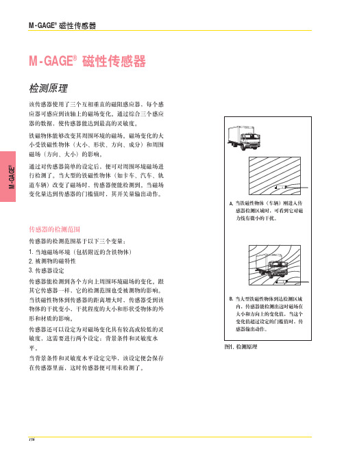
156M -G A G E ®M-GAGE ®磁性传感器检测原理该传感器使用了三个互相垂直的磁阻感应器,每个感应器可感应到该轴上的磁场变化。
通过综合三个感应器的数据,使传感器能达到最高的灵敏度。
铁磁物体能够改变其周围环境的磁场。
磁场变化的大小受铁磁性物体(大小、形状、方向、成分)和周围磁场(方向、大小)的影响。
通过对传感器简单的设定后,便可对周围环境磁场进行检测了。
当大型的铁磁性物体(如卡车、汽车、轨道车辆)改变了磁场时,传感器便能检测到。
当磁场变化量达到传感器的门槛值时,其开关量输出动作。
传感器的检测范围传感器的检测范围基于以下三个变量:1. 当地磁场环境(包括附近的含铁物体)2. 被测物的磁特性3. 传感器设定传感器能检测到各个方向上周围环境磁场的变化。
跟其它传感器一样,它的检测范围也受被测物的影响。
当铁磁性物体到传感器的距离增大时,传感器受到该物体的干扰变小,干扰程度的大小和形状受物体的外形和材质的影响。
传感器还可以设定为对磁场变化具有较高或较低的灵敏度,这需要进行两个设定:背景条件和灵敏度水平。
当背景条件和灵敏度水平设定完毕,该设定便会保存在传感器里面,这时传感器便可用来检测了。
图1. 检测原理 • Email: sensors@ 157M-GAGE ®典型目标过量增益曲线当传感器被牢固安装并完成设定后,就可以投入运行了。
以下两个例子就是M-GAGE 传感器的典型应用:实例1描述的是把M-GAGE 传感器安装在地面上1米来检测车辆的,如图所示。
图2标示的就是传感器在这个应用中的过量增益曲线图,图中的过量增益值是一个反映被测物被传感器可靠检测到所需要的数值,它比传感器的门槛值要大,该应用实例是将传感器设定在第5级灵敏度。
右表记录了传感器灵敏度设定变化后,过量增益值的改变。
如果灵敏度为第6级,那么对于相同的检测距离,其过量增益值是第5级灵敏度时的1.3倍。
同样地,当灵敏度设定在第1级,其过量增益值只有第5级时的1/3。
德国SIKO 量测模组,磁栅尺,磁性尺技术参数

● 磁性尺测量系统专为线性位移测量而设计.
● 经济,效率特别适用于长距离的测量.
● 特别适用于如油污,切削屑,震动等恶劣环境
* 依应用性质不同可定义出两个不同的系统
磁性尺测量系统:使用于线性位移测量并于显示器显示测量值
磁性编码器:使用于线性位移பைடு நூலகம்量并将位移量转换为对应的脉波数输出给PLC或控制器
测量范围50mm-3000mm
测量准确度±6um/m~±10/m
测量基准:光栅周期20um的光学玻璃尺
光学测量系统:透射式红外线光测量系统,红外线波长880nm
反应速度:60m/min(0.005mm),25m/min(0.001mm)
读数头滑动系统:垂直式五轴承
输出讯号:TTL/EIA-422-A,讯号传达周期:20um,供电电压:DC5±5%
尺带长度:Max 32M
磁 间 距:2+2mm、1+1mm
产品优点
●非接触式测量,无背隙问题
●高抗污染能力
●安装简易,安装允许误差大
●价格便宜
主要市场
金属加工设备 建材机械 木工机械 测量机 精密平台
【 磁性尺量测模组 】
——德国SIKO 量测模组,磁栅尺,磁性尺,磁尺,磁条,磁头,磁环,磁性显示器,电子显示器,位置指示器,计数器,手轮,重垂表,拉绳编码器,磁性编码器,电位编码器
电话0631-5997499 传真 0631-3631966 QQ815488790 邮箱whsfrf@
德国SIKO磁栅尺读头
分辨率:0.025、0.01、0.005、0.001、0.0005mm
输出 :正交差动方波
线长 :8米
Magtrol HD系列磁滞动力计说明书
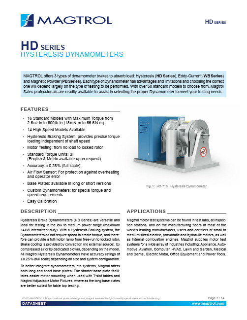
HD SERIES HD SERIESHYSTERESIS DYNAMOMETERSMAGTROL offers 3 types of dynamometer brakes to absorb load: Hysteresis (HD Series), Eddy-Current (WB Series) and Magnetic Powder (PB Series). Each type of Dynamometer has advantages and limitations and choosing the correct one will depend largely on the type of testing to be performed. With over 50 standard models to choose from, Magtrol Sales professionals are readily available to assist in selecting the proper Dynamometer to meet your testing needs.FEATURES▪16 Standard Models with Maximum Torque from2.5 oz·in to 500 lb·in (18 mN·m to 56.5 N·m)▪14 High Speed Models Available▪Hysteresis Braking System: provides precise torqueloading independent of shaft speed▪Motor Testing: from no load to locked rotor▪Standard Torque Units: SI(English & Metric available upon request)▪Accuracy: ± 0.25 % (full scale)▪Air Flow Sensor: For protection against overheatingand operator error▪Base Plates: available in long or short versions▪Custom Dynamometers: for special torque andspeed requirements▪Easy CalibrationDESCRIPTIONHysteresis Brake Dynamometers (HD Series) are versatile and ideal for testing in the low to medium power range (maximum 14 kW intermittent duty). With a Hysteresis Braking system, the Dynamometers do not require speed to create torque, and there-fore can provide a full motor ramp from free-run to locked rotor. Brake cooling is provided by convection (no external source), by compressed air or by dedicated blower, depending on the model. All Magtrol Hysteresis Dynamometers have accuracy ratings of ± 0.25 % (full scale) depending on size and system configuration. To better integrate dynamometers into systems, Magtrol offers both long and short base plates. The shorter base plate facili-tates easier motor mounting when used with T-slot tables and Magtrol Adjustable Motor Fixtures, where as the long base plates are better suited for table top testing.APPLICATIONSMagtrol motor test systems can be found in test labs, at inspec-tion stations, and on the manufacturing floors of most of the world’s leading manufacturers, users and certifiers of small to medium sized electric, pneumatic and hydraulic motors, as well as internal combustion engines. Magtrol supplies motor test systems for a wide array of industries including: Appliance, Auto-motive, Aviation, Computer, HVAC, Lawn and Garden, Medical and Dental, Electric Motor, Office Equipment and Power Tools.Fig. 1: HD-715 | Hysteresis DynamometerMagtrol’s Hysteresis Dynamometers cover a wide range of Torque, Speed and Mechanical Power ratings. To select the appropriate size Dynamometer for your motor testing needs, you will need to determine the Maximum Torque, Speed and Power applied to the Dynamometer.MAXIMUM TORQUEThe Magtrol Hysteresis Absorption Dynamometer will develop braking torque at any speed point, including low speed and stall conditions ("0" rpm). It is important to consider all torque points that are to be tested, not only rated torque, but also locked rotor and breakdown torque. Dynamometer selection should initially be based on the maximum torque requirement, subject to determining the maximum power requirements. MAXIMUM SPEEDThis rating is to be considered independent of torque and power requirements, and is the maximum speed at which the Dynamometer can be safely run under free-run or lightly loaded conditions. It is not to be considered as the maximum speed at which full braking torque can be applied.MAXIMUM POWER RATINGSThese ratings represent the maximum capability of the Dyna-mometer Braking System to absorb and dissipate heat gener-ated when applying a braking load to the motor under test. The power absorbed and the heat generated by the Dynamometer is a function of the Torque (T) applied to the motor under test, and the resulting Speed (n) of the motor. This is expressed in these Power (P) formulas:The Dynamometer’s ability to dissipate heat is a function of how long a load will be applied. For this reason, the maximum power ratings given are based on continuous operation under load, as well as a maximum of 5 minutes under load.To safely dissipate heat and avoid Dynamometer failure, the maximum power rating is the most important consideration in selecting a Dynamometer.Magtrol Hysteresis Dynamometers absorb power with a unique Hysteresis Braking Systemwhich provides frictionless torque loading independent of shaft speed. The HysteresisBrake provides torque by the use of two basic components - a reticulated pole structureand a specialty steel rotor/shaft assembly - fitted together but not in physical contact.Until the pole structure is energized, the drag cup can spin freely on its shaft bear-ings. When a magnetizing force from the field coil is applied to the pole structure,the air gap becomes a flux field and the rotor is magnetically restrained, providinga braking action between the pole structure and rotor.Magtrol’s M-TEST Software isa state-of-the-art motor testingprogram for Windows®-baseddata acquisition. Used with aMagtrol DSP 7010 Dynamom-eter Controller, Magtrol M-TESTSoftware provides the control ofany Magtrol Dynamometer and runs test sequences in a manner best suited to the overall accuracy and efficiency of the Magtrol Motor T est System. The data that is generated by Magtrol’s Motor T esting Software can be stored, dis-played and printed in tabular or graphic formats, and can be easily imported into a spreadsheet.Written in LabVIEW™, M-TEST has the flexibility to test a majority of motor types in a variety of ways. Because of LabVIEW’s versatility, obtaining data from other sources (e.g. thermocouples), controlling motor power and providing audio/visual indicators is relatively easy. Magtrol’s M-TEST Software is ideal for simulating loads, cycling the unit under test and motor ramping. Because it is easy to gather data and duplicate tests, the software is ideal for use in engineering labs. T ests can be programmed to run on their own and saved for future use allowing for valuable time savings in production testing and incoming/outgoing inspection.SI: P[W] = T[N·m] × n[min-1]× (1.047 x 10-1) English: P[W] = T[lb·in] × n[rpm]× (1.183 x 10⁻²) Metric: P[W] = T[kg·cm] × n[rpm]× (1.027 x 10⁻²) All of Magtrol’s controllers, readouts and software calculate horsepower as defined by 1 [hp] = 550 [lb·ft /s].Using this definition:P[hp] = P[W] / 745.7Pole StructureBearingAir GapOPEN LOOP SYSTEMSMagtrol offers both open loop manual test systems and PC-based closed loop test systems. A typical open loop system will consist of a Dynamometer and a Magtrol DSP 7010 Dynamom-eter Controller in Open-Loop configuration. A Magtrol Single or Three-Phase Power Analyzer, which allows for the capturing of volts, amps, watts and power factor, can be included as an option. An open loop system is often used for quick pass / fail testing on the production line or at incoming inspection. Magtrol’s DSP 7010 Dynamometer Controller provides pass / fail testing as a standard feature.CLOSED LOOP SYSTEMSIn a closed loop motor test system, data is collected on a PC using Magtrol’s M-TEST Software, DSP 7010 Dynamometer Controller, and requisite interface cards and cables. Magtrol’s DSP 7010 Dynamometer Controllers compute and display mechanical power (in horsepower or watts) in addition to torque and speed. A Single or Three Phase Power Analyzer, a required component in a test system measuring motor efficiency, can be integrated into this system as well as Magtrol’s Temperature Testing Hardware.MODEL 7500Computer witha) All -5C dynamometers are 5 Volt Output.Please, contact our sales representative for 6C (English units), 7C (Metric units) or 8C (SI units) specifications.b) Operating at the continuous power rating for periods of up to 4 hours isacceptable. However, operating for extended periods at high temperatures will result in premature component and bearing failure. Limiting the length of the cycle and the component temperatures will guard against premature failure. Where continuous duty is desired for longer time intervals, compo-nent temperatures should be maintained less than 100°C; monitoring the outside brake surface temperature is a sufficient reference.c) Requires air cooling provided by user. Regulator and filter package isprovided as standard d) Blower is includede) The maximum speed will depend on what type of keyway (if any) is usedon the shaft. Unless specified, the dynamometer shaft will be made withouta keyway.ELECTRICAL POWERHD-100 / 400 / 500 SERIES WITH LONG BASE PLATEb) Shaft Flats are not available on high speed models.a) These dimensions represent the distance between mounting holes. Thereare four (4) mounting holes on each base plate.HD-100 / 400 / 500 SERIES WITH SHORT BASE PLATEb) Shaft Flats are not available on high speed models.a) These dimensions represent the distance between mounting holes. Thereare four (4) mounting holes on each base plate.a) These dimensions represent the distance between mounting holes. Thereare four (4) mounting holes on each base plate.b) Shaft Flats are not available on high speed models.are four (4) mounting holes on each base plate.a) These dimensions represent the distance between mounting holes. There are four (4) mounting holes on each base plate.BLOWER POWER▪Models HD-710, HD-715 & HD-810 include the BL-001 blower.▪Models HD-815 include the BL-002 blower. ▪Model HD-825 uses two BL-002 blowers for cooling its two brake sets.On / Off Switch120/240 V AC / 50/60 HzAllow approximately 6 in to 8 in (152 mm to 203 mm) between rear of dynamom-eter base plate and blower for connection hardware. Required hardware is sup-plied with the dynamometer.BL-002 Blower has two filter elements.HD 106 & HD 106 HSHD-100 & HD 100 HSHD 400 & HD 400 HSHD 500 & HD 500 HS30 00040 00050 00060 000Maximum Rated Speed for standard versionMaximum Rated Speed for High Speed version m )0.0000.0020.0040.0060.0100.0120.0140.0160.018010 00020 00030 00040 00050 00060 000S P E E D (r p m )TORQUE (N·m )0.000.010.020.030.040.050.060.070.085 00010 00020 00025 00030 00035 00040 00045 00015 000S P E E D (r p m )TORQUE (N·m )HD 510 & HD 510 HSHD 505 & HD 505 HSHD 515 & HD 515 HSHD 700 & HD 700 HSHD 710 & HD 710 HSHD 705 & HD 705 HS5 00010 00020 00025 00030 00015 00035 00040 00045 0000.10.00.20.30.40.50.60.70.8S P E E D (r p m )TORQUE (N·m )0.000.250.500.751.001.251.505 00010 00020 00025 00030 00015 00035 00040 00045 000S P E E D (r p m )TORQUE (N·m )0.000.250.500.751.001.251.505 00010 00020 00025 00030 00015 00035 00040 00045 000S P E E D (r p m )TORQUE (N·m )0.00.5 1.0 1.5 2.0 2.5 3.05 00010 00020 00025 00030 00015 00035 00040 000S P E E D (r p m )TORQUE (N·m )0.00.51.01.52.02.53.0 05 00010 00020 00025 00030 00035 00040 00015 000S P E E D (r p m )0.01.02.03.04.05.06.05 00010 00020 00025 00030 00015 00035 00040 000S P E E D (r p m )HD 715 & HD 715 HSHD 800HD 805HD 810 & HD 810 HSHD 815 & HD 815 HSHD 825 & HD 825 HS0.01.02.03.04.05.06.0 05 00010 00020 00025 00030 00040 00035 00015 000S P E E D (r p m )TORQUE (N·m)0.02.0 4.0 6.08.012.010.014.04 000 2 0006 00010 00012 00014 0008 000S P E E D (r p m )TORQUE (N·m)0.05.010.015.020.025.02 0004 0006 0008 00010 00012 00014 000S P E E D (r p m )TORQUE (N·m )0.02.0 4.08.06.010.012.014.04 000 2 0006 00010 00012 00014 00016 0008 000S P E E D (r p m )TORQUE (N·m )0.05.010.015.020.025.04 000 2 0006 00010 00012 00014 00016 0008 000S P E E D (r p m )TORQUE (N·m )0.010.020.030.040.050.02 0004 0006 0008 00012 00010 000S P E E D (r p m )TORQUE (N·m )The power absorption curves represent the maximum power (heat) that the dynamometer can dissipate over time.HD SERIESHD Series Hysteresis Dynamometers can be incorporated into a Customized Motor Test System (CMTS )These PC based, turn-key systems arecustom designed and built to meet specific user requirements.Various devices such as dynamometer con-trollers, power analyzers or other customized devices can be easily integrated into a 19" rack system (in an external cabinet or directly in the table).These systems integrate specific software (such as M-TEST) to facilitate the measure-ment process.ENCODER OPTIONS FOR LOW SPEED TESTINGFor low speed motors, such as gear motors with maximum speeds of less than 200 rpm, Magtrol offers additional encoder options that allow for increased resolution of the speed signal.T-SLOT BASE PLATETo accommodate Magtrol AMF-3 Adjustable Motor Fixtures, a grooved base plate with three M12 T-slots, one centered and two 250 mm apart, is available on all HD-8XX series dynamometers.MECHANICAL CUSTOMISATIONSMagtrol is highly experienced and qualified in the customization of its products. We can provide custom-ized base plates, riser blocks and shaft modifications.Our specialized salesmen and technicians are at your service to help you find the best configuration for your project.a) In case of special design the 4 last digits will be specific; please contactour sales representative b) Please contact our sales representative regarding long base plate c) PPR means Pulse Per RevolutionExample: HD Series Dynamometer, model 106, supply in 240 V A C, shortbase plate, 60-PPR encoder and standard version would be ordered as follows: HD-106-5C2-0100HD Series Dynamometer, model 805, supply in 120 V A C, long base plate with T-slot, 6000-PPR encoder and high speed version would be ordered as follows: HD-805-5C1-024HCABLE ASSEMBLYa) Other lenght available on requestDynamometer TableBlowerAdjustable Motor FixtureMotor Under TestHeavy-duty Equipment RackFully customizable (19" rack standards)Control screen(optional touchscreen)Command Panel(allows easy access to the main functions)Connection Panel To connect external devices or options spe-cific to the test bench (temperature probe,...)DSP 7010 Series Dynamometer Controller MODEL 7500 SeriesPower AnalyzerFull Computer (inlcuding rack mounted keyboard,...)Free rack mounted spacefor third-party equipment (e.g. power supply, measuringinstrument, etc...)© 2023 MAGTROL | Due to continual product development, Magtrol reserves the right to modify specifications without forewarning.Page 14 / 14DATASHEETI E S - U S 06 / 2023HD SERIESSYSTEM OPTIONS AND ACCESSORIESDSP 7010 - DYNAMOMETER CONTROLLERSMagtrol’s MODEL DSP 7010 Series Dynamometer Controller employs state-of-the-art Digital Signal Processing Technol-ogy to provide superior motor testing capabilities. Designed for use with any Magtrol Hysteresis, Eddy-Current or Powder Dynamometer, Magtrol In-Line Torque Transducer or auxiliary instrumentation, the DSP 7010 can provide complete PC control via the USB or IEEE-488 interface. With up to 500 readings per second, the DSP 7010 is ideally suited for both the test lab and the production line.WB & PB SERIES - DYNAMOMETERThe WB Series (eddy current) and PB Series (magnetic powder) dyna-mometers are particularly suitable for demanding applications requiring low (PB) to high (WB up to 65 000 rpm) speeds. The PB brakes will develop their nominal torque atstandstill, while the WBbrakes develop a braking torque proportional to the speed and their maximum torque is reached at nominal speed. The brake is cooled by water circulating in the stator. As a result, these dynamometers are able to dissipate high continuous loads (up to 140 kW). The WB and PB dynamometers incorporate a torque measuring system which has an accuracy of ± 0.3 % to ± 0.5 % at full scale.MODEL 7500 - POWER ANALYZERSThe Magtrol MODEL 7500 Power Analyzer is an easy-to-use instrument ideal for numerous power measurement applications. From DC to 80 kHz, the MODEL 7500 measures volts, amps, watts, volt-amps, frequency, crest factor, Vpeak, Apeak and power factor in one convenient display. They may be used either as stand-alone instruments or in conjunction with any Magtrol Hysteresis, Eddy-Current or Powder Brake Dynamometer; any Magtrol Dynamometer Controller and M-TEST Software for more demanding motor test applications.AMF SERIES - MOTOR FIXTURESPositioning and alignment have a great influence on the measured parameters (friction torque). MAG-TROL strongly recommends a sup-port specifically dedicated to the products to be tested to ensure the best positioning tolerances in X-Y , and its repeatability.Alternatively, Magtrol AMF Series (Adjustable Motor Fixtures) can be used. These extremely versatile fixtures can accommodate motors up to 101 m m (4") in diameter. It enables easy motor centering during testing, but does not have centering references.TAB SERIES - DYNAMOMETER TABLESTest from a stationary position or move a dynamometer to alternate testing stations with ease with Magtrol’s Dynamometer Table. The stand is designed from lightweight aluminum with casters for smooth mobility, and is sturdy enough to support even the heaviest of Magtrol dynamometers. The design can be retrofitted to any Magtrol dynamometer and is easily reconfigured for added versatility.Fig. 7: DSP 7011 | Programmable Dynamometer ControllersFig. 8: 1 PB 115 | Powder DynamometerFig. 9: MODEL 7510 | Power AnalyzersFig. 10: T AB Series | Dynamometer Tables。
电子尺、光栅尺、编码器和磁致伸缩位移传感器的对比

50mm~3000mm
80~12000mm
接口
TTL/EIA-422-A
RS232、RS485、RS422
寿命
一亿次
安装方式
参考价格(1米)
1500元
2500元
缺点
1、精度、可靠性、行程、寿命上稍差
2、接触式测量,磨损严重
3、不耐恶劣环境
1、承受不了环境的震荡和冲击ቤተ መጻሕፍቲ ባይዱ
2、安装空间、机械间隙和长期维护很麻烦。
电子尺(参考米诺和GEFRAN)
光学编码器
光栅尺
磁尺
工作原理
利用改变阻值的线性变化量达到量测目的。
由一个中心有轴的光电码盘,其上有环形通、暗的刻线,有光电发射和接收器件读取,获得四组正弦波信号组合成A、B、C、D,每个正弦波相差90度相位差(相对于一个周波为360度),将C、D信号反向,叠加在A、B两相上,可增强稳定信号;另每转输出一个Z相脉冲以代表零位参考位。由于A、B两相相差90度,可通过比较A相在前还是B相在前,以判别编码器的正转与反转,通过零位脉冲,可获得编码器的零位参考位。
光栅位移传感器的工作原理,是由一对光栅副中的主光栅(即标尺光栅)和副光栅(即指示光栅)进行相对位移时,在光的干涉与衍射共同作用下产生黑白相间(或明暗相间)的规则条纹图形,称之为莫尔条纹。经过光电器件转换使黑白(或明暗)相同的条纹转换成正弦波变化的电信号,再经过放大器放大,整形电路整形后,得到两路相差为90o的正弦波或方波,送入光栅数显表计数显示。
浅谈磁性液位计的原理和应用

浅谈磁性液位计的原理和应用1. 磁性液位计的原理磁性液位计是一种测量液体高度的仪器仪表,它主要依靠液位计的磁性特性进行测量。
其原理可以分为以下几个方面:1.1 磁性标尺磁性标尺是磁性液位计的主要组成部分之一。
磁性标尺由一系列的磁性导线组成,其中的每个磁性导线都与液体的液位高度相对应。
当液体的液位发生变化时,磁性标尺也会随之产生相应的变化。
1.2 磁性浮子磁性浮子是磁性液位计的另一个重要组成部分。
磁性浮子通常由磁性材料制成,它可以根据液位的高低在液体中自由浮动。
磁性浮子的位置变化会对应产生磁场的变化,从而通过传感器来测量液位的变化。
1.3 传感器传感器是磁性液位计中起到接收并处理磁场信号的装置。
它主要通过感应测量磁性浮子所产生的磁场变化,并将测量结果转化成液位的高度。
传感器可以根据测量原理的不同分为多种类型,比如磁阻式传感器、磁感应式传感器等。
1.4 显示仪表显示仪表是磁性液位计的最后一个组成部分。
它通常用于实时显示液体的液位高度,方便操作人员进行观察和监控。
显示仪表可以采用数字显示、模拟仪表等形式,根据具体的应用需求来选择合适的类型。
2. 磁性液位计的应用磁性液位计具有以下几个方面的应用:2.1 石油化工行业磁性液位计在石油化工行业中广泛应用于储罐液位的测量。
它可以准确地测量储罐中各种液体的液位变化,帮助操作人员掌握储罐中液体的存量情况,从而更好地进行生产计划和物料管理。
2.2 食品加工行业磁性液位计在食品加工行业中主要用于液体的储存和搅拌等过程中的液位检测。
通过磁性液位计可以实时监测液体的液位变化,提前预警液位过高或过低的情况,确保生产过程的安全和稳定。
2.3 污水处理行业磁性液位计在污水处理行业中用于测量污水处理池中液位的变化。
通过监测液位的变化,可以掌握处理池中污水的流量和液位的变化情况,及时采取相应的处理措施,确保污水处理的效果和质量。
2.4 自动化生产线磁性液位计还被广泛应用于各类自动化生产线上,用于检测流程管道中的液位变化。
永磁体基本性能参数

永磁体基本性能参数永磁材料:永磁材料被外加磁场磁化后磁性不消失,可对外部空间提供稳定磁场。
钕铁硼永磁体常用的衡量指标有以下四种:剩磁(Br)单位为特斯拉(T)和高斯(G)1G=0.0001T将一个磁体在闭路环境下被外磁场充磁到技术饱和后撤消外磁场,此时磁体表现的磁感应强度我们称之为剩磁。
它表示磁体所能提供的最大的磁通值。
从退磁曲线上可见,它对应于气隙为零时的情况,故在实际磁路中磁体的磁感应强度都小于剩磁。
钕铁硼是现今发现的Br最高的实用永磁材料。
磁感矫顽力(Hcb)单位是安/米(A/m)和奥斯特(Oe)或1Oe≈79.6A/m处于技术饱和磁化后的磁体在被反向充磁时,使磁感应强度降为零所需反向磁场强度的值称之为磁感矫顽力(Hcb)。
但此时磁体的磁化强度并不为零,只是所加的反向磁场与磁体的磁化强度作用相互抵消。
(对外磁感应强度表现为零)此时若撤消外磁场,磁体仍具有一定的磁性能。
钕铁硼的矫顽力一般是11000Oe以上。
内禀矫顽力(Hcj)单位是安/米(A/m)和奥斯特(Oe)1Oe≈79.6A/m使磁体的磁化强度降为零所需施加的反向磁场强度,我们称之为内禀矫顽力。
内禀矫顽力是衡量磁体抗退磁能力的一个物理量,如果外加的磁场等于磁体的内禀矫顽力,磁体的磁性将会基本消除。
钕铁硼的Hcj会随着温度的升高而降低所以需要工作在高温环境下时应该选择高Hcj的牌号。
磁能积(BH)单位为焦/米3(J/m3)或高奥(GOe)1MGOe≈7.96kJ/m3退磁曲线上任何一点的B和H的乘积既BH我们称为磁能积,而B某H的最大值称之为最大磁能积(BH)ma某。
磁能积是恒量磁体所储存能量大小的重要参数之一,(BH)ma某越大说明磁体蕴含的磁能量越大。
设计磁路时要尽可能使磁体的工作点处在最大磁能积所对应的B和H附近。
各向同性磁体:任何方向磁性能都相同的磁体。
各向异性磁体:不同方向上磁性能会有不同;且存在一个方向,在该方向取向时所得磁性能最高的磁体。
高精度磁尺基本原理简介
联系人:王葛,男,电气助理技师,鞍钢热轧带钢厂 (114()21)。
与r一的相位差角可作为r一过零点(基准点)的偏
^ ’~‘’~4^’’’、’。‘、’+’’^’~4’’4^’、’’,。、7、’‘’、,。’4^1’、‘,’、’’’,。、7’’r’^
新口铁成功开发超高加工性铁素体不锈钢板
3 MⅡ)一SCALE系统的基本原理 3.1 MP--SCAIE的传感器原理
(1)h口一SCAI正的原理基础 根据电磁感应定律,如果有一个矩形线圈A 靠近通电矩形线圈B,并有相对运动产生时,在A 线圈中将产生感应电势,令激磁线圈R中通以电 流为:j—lsin r=ot。 接有电压表的A线圈为感应线圈,图2所示 方向与B线圈靠近,当A线圈相对于B线圈产生 相对运动时,则随两个线圈的相对位置不同。其感 应电势r也不同。图2示出了两个线圈运动中的 几种典型位移。
移动到r/2时,定尺绕组中将感应出与图3(1)位 置极性相反的最大感应电势(3点)。动尺再移动 到图3(d)位置(3r/4),定尺中感应电势又为零(4 点)。当动尺相对于定尺向右移动到一个节距(r) 时,如图3(5)位置,此时定尺绕组中的感应电势eS 又回到与1点相同的最大值,
通过上述分析可知,动尺相对于定尺在空问 中移动一个节距(r),定尺绕组中感应电势es的变
新日铁公司通过采用高功率真空精炼、连铸技术,以及在热轧至冷轧各个生产工序中使用金相组织 控制技术.成功开发出加工性能、深冲性能极高的铁索体不锈钢板(Y【点PDx)。该钢板尽管属于铁素体 不锈钢,但萁具备了奥氏体不锈钢的代表SUS304所具有的加工性能和冲压成形性能。
以前的铁素体不锈钢的代表S1...N430与含有镍的奥氏体不锈钢相比,断裂前的延伸率低且成形性 差。新丌发的YI.JSPDX钢板,通过采用高功率真空精炼技术,使造成延伸率降低的夹杂物大幅减少,而 且所添加的合金元素钛降到了最低限度,致使其与以前的铁素体不锈钢SUS430相比,延伸率的绝对值 可增加1 0p,,而日在延伸率达到40%的情况下,R直也可增加到2.0,加工时的深冲性也极大提高。
雷尼绍磁栅尺说明书

雷尼绍磁栅尺说明书一、介绍1.1 什么是雷尼绍磁栅尺?雷尼绍磁栅尺是一种用于测量物体长度或位移的精密测量仪器。
它采用了磁栅栅标的原理,结合高精度传感器和计数器,能够快速、准确地测量目标长度或位移。
1.2 雷尼绍磁栅尺的主要特点•高精度:雷尼绍磁栅尺具有很高的分辨率和重复性,并且能够进行微调以提高精度。
•稳定性好:磁栅标的固定在测量物体上,不易受外部环境的干扰,保证测量结果的稳定性。
•耐用性强:雷尼绍磁栅尺采用高品质材料和工艺制造,具有较强的抗震、抗压和耐磨性能,使用寿命长。
•易于安装和操作:雷尼绍磁栅尺设计简洁,安装方便,操作简单,适用于各种工作环境。
二、原理2.1 磁栅栅标原理雷尼绍磁栅尺的核心部件是磁栅栅标。
磁栅栅标是由一系列磁极和非磁性隔离层组成的。
当磁栅栅标在磁场中运动时,磁极与传感器之间会产生磁场的改变,通过检测这种磁场的变化可以确定目标的长度或位移。
2.2 传感器和计数器雷尼绍磁栅尺使用了高精度的传感器来检测磁场的变化,并将信号转换成数字信号。
通过计数器可以实时记录磁栅栅标的位置,从而得到测量结果。
2.3 工作原理雷尼绍磁栅尺在测量前首先通过校准程序对传感器进行校准,以提高测量的准确性。
然后将磁栅栅标固定在待测物体上,启动测量程序。
当待测物体移动时,磁栅栅标产生磁场的变化,传感器会感知到这种变化并发送信号给计数器进行处理。
计数器会记录磁栅栅标相对参考位置的偏移量,并将其转换成实际的长度或位移值。
三、使用方法3.1 安装•将雷尼绍磁栅尺固定在需要测量的物体上,确保其与待测物体保持紧密接触。
•连接电源,确保供电正常。
3.2 校准•打开校准程序,按照提示进行校准。
校准过程通常包括调整传感器位置、检查磁栅栅标的位置等步骤。
•校准完成后,关闭校准程序。
3.3 测量•打开测量程序,选择需要测量的模式和单位。
•将待测物体移动到所需位置,测量程序会实时显示测量结果。
•如果需要进行多次测量,可以记录测量结果并进行平均以提高精度。
绝对值直线电机模组 磁栅尺-概述说明以及解释

绝对值直线电机模组磁栅尺-概述说明以及解释1.引言1.1 概述绝对值直线电机模组和磁栅尺是现代工业自动化领域中常见的关键元件,它们在精密定位和控制方面发挥着重要作用。
本文将深入探讨这两种技术,并分析它们的应用和优势。
绝对值直线电机模组是一种具有高精度和高速度的直线电机系统,通过内置的编码器可以实现绝对位置的测量,无需进行复位操作即可准确获取位置信息。
磁栅尺则是一种利用磁场测量技术实现位置检测的装置,可以提供高精度的位置反馈信号,广泛应用于数控机床、印刷设备、机器人和其他自动化设备中。
通过对绝对值直线电机模组和磁栅尺的深入研究,可以更好地了解它们的原理和特点,为工业自动化领域的发展提供有益参考。
"1.2 文章结构"部分内容:本文主要分为引言、正文和结论三个部分。
在引言部分,将介绍绝对值直线电机模组和磁栅尺的概念,并阐明本文的目的。
在正文部分,将详细介绍绝对值直线电机模组和磁栅尺的原理、结构和工作原理,以及它们在工业领域中的应用和优势。
在结论部分,将对本文进行总结,展望未来可能的发展方向,提出一些结论和建议。
通过这种结构安排,读者可以清晰地了解本文的内容,并全面了解绝对值直线电机模组和磁栅尺在工业生产中的重要作用。
1.3 目的本文的主要目的是介绍绝对值直线电机模组和磁栅尺在工业自动化领域的应用。
通过对这两种技术的详细介绍和分析,可以帮助读者更好地理解它们的原理和特点,以及它们在工业生产中的优势和应用场景。
同时,本文也旨在促进这些先进技术的推广和应用,推动工业自动化领域的发展,并为相关领域的研究者和从业人员提供更多的参考和借鉴。
通过深入了解和掌握这些技术,我们可以更好地提高生产效率、降低成本,实现智能化制造,推动工业产业的升级和发展。
2.正文2.1 绝对值直线电机模组:绝对值直线电机模组是一种先进的电动执行器,具有高精度、高速度和高可靠性的特点。
它采用直线电机作为动力源,通过电磁感应原理实现直线运动。
德国SIKO量测模组磁栅尺磁性尺技术参数

德国SIKO量测模组磁栅尺磁性尺技术参数SIKO是德国的一家专业生产测量模块、磁栅尺和磁性尺的公司。
以下是SIKO产品的一些技术参数的详细介绍。
1.SIKO测量模块技术参数:-运动方式:根据应用需求可以选择不同的传感器类型,包括:非接触式霍尔传感器、光电传感器、螺旋线编码器等。
- 精度:可根据测量模块的类型达到不同的精度要求,一般在±0.01mm或更高精度。
- 分辨率:可根据传感器类型达到不同的分辨率要求,一般在0.01mm或更高精度。
-供电电压:一般为DC5V或24V,也可根据需要定制其他电压。
-输出信号:一般为数字信号,可根据需求定制模拟信号输出。
2.SIKO磁栅尺技术参数:-量程:磁栅尺可根据应用需求选择不同的量程,一般可达到几米到十几米的范围。
-分辨率:一般为0.1μm或更高的分辨率,根据需求可定制更高的分辨率。
-精度:一般为±5μm或更高的精度要求。
-工作温度:一般为-10℃至+80℃,也可根据需要定制更高或更低的工作温度范围。
-供电电压:一般为DC5V或DC9V-30V,也可根据需要定制其他电压。
3.SIKO磁性尺技术参数:-量程:磁性尺可根据应用需求选择不同的量程,一般可达到几厘米到几米的范围。
- 分辨率:一般为0.01mm或更高的分辨率,根据需求可定制更高的分辨率。
- 精度:一般为±0.05mm或更高的精度要求。
-工作温度:一般为-10℃至+80℃,也可根据需要定制更高或更低的工作温度范围。
-供电电压:一般为DC5V或DC10V-30V,也可根据需要定制其他电压。
以上是关于德国SIKO量测模组、磁栅尺和磁性尺的一些技术参数的详细介绍。
这些技术参数可以根据具体的应用需求进行选择和定制,以满足不同的测量要求。
磁栅无线卡尺操作方法

磁栅无线卡尺操作方法磁栅无线卡尺是一种精密测量工具,通常用于测量物品的长度、深度和宽度等尺寸参数。
与传统的卡尺不同,磁栅无线卡尺使用数字显示屏幕,使操作更加简便,并提高了测量精度。
在本文中,我们将详细介绍磁栅无线卡尺的操作方法。
第一步:准备工作在使用磁栅无线卡尺之前,需要进行一些准备工作。
首先,要确保卡尺处于正常工作状态。
启动磁栅无线卡尺,确认数字显示屏幕上的数字为零。
同时,需要确定是否有足够的电量。
因为如果卡尺电量不足,测量结果可能会出现偏差。
第二步:测量操作1. 单位选择磁栅无线卡尺支持多种尺寸单位,如毫米、英寸、分米等。
可以通过“单位选择”按钮选择需要的单位。
在数字显示屏幕上,会显示选定单位的缩写。
2. 零点设置为了保证测量的准确性,需要在测量前对卡尺的零点进行清零操作。
在使用时,将卡尺底部对准测量物品的一端,并按下“清零”按钮,数字显示屏幕会显示为零。
3. 测量对象将卡尺端面平放在测量目标上,并移动卡尺的其他端口,直到它在测量对象的另一端。
卡尺顶部的数字显示屏幕上会显示卡尺的长度值。
为了提高磁栅无线卡尺的测量精度,需要重复测量目标的多个部位,并将所得数值求平均值。
在连续测量时,可以使用“保持”按钮,将当前值保留在数字显示屏幕上,以便于稍后的数据处理。
4. 数据输出除了数字显示屏幕上的数值之外,磁栅无线卡尺还可以将数据输出到计算机或其他存储设备中。
使用卡尺附带的USB线将卡尺连接到计算机上。
在卡尺主机上按下“数据输出”按钮,数值数据将同时保存在卡尺主机和计算机中。
注意事项在使用磁栅无线卡尺时,应注意以下事项:1. 磁栅无线卡尺是一种精密测量工具,在使用过程中应当小心谨慎。
避免硬物撞击、重压、摔落以及其他不当操作。
2. 在使用磁栅无线卡尺时,需要避免受到外界干扰,例如电磁干扰、震动、温度变化等干扰,以保证测量精度。
3. 如果卡尺不再使用,应及时关闭电源,并妥善保管,以避免损坏或丢失。
总结磁栅无线卡尺是一种精密测量工具,可用于测量物品的长度、深度和宽度等尺寸参数。
可移动铂酸磁米仪G-856AX产品说明书

Portable Proton MagnetometerM o d e l G-856AX∙0.1 nT resolution and sensitivity Designed for ease of use by non-skilled personnel∙Digital memory - 12,500 readings ∙Manual data recall, or down load to a PC∙Versatile, total field, gradiometer or base station use ∙Rugged weatherproof construction.unit provides a repeatable absolute total field magnetic reading, traceable to the National Bureau of Standards, unlike other magnetic field measurement processes which measure only a single component of the field.Applications:The G-865AX is ideal for mapping geological structures, for mineral exploration, magnetic search for industrial, environmental or archaeological targets. The optionalgradiometer attachment gives greater resolution and noise immunity for conducting searches in industrial or high cultural noise environments. Simple operation, large digital data storage capability, and the inclusion of MagMap2000 data transfer and editing software provides a system well suited for both teaching and survey applications.The automated cycling option with long sensor cable and external power connection allows use of the G-856AX as a base station unit for the measurement of diurnal changes in the earth’s magnetic field. Diurnal correction data is then downloaded by MagMap2000 and can be applied to other856, 858 or 822/823 airborne data.The G-856 provides a reliable, low cost solution for a variety of magnetic search and mapping applications. Single key strokeoperation means the G-856AX can be operated by non-technical field personnel or used in teaching environments. The G-856AX uses the established proton precession method,allowing accurate measurements to be made with virtually no dependence upon variables such as sensor orientation, temperature, orlocation. TheG-856 Console and Sensor1981Superior Data Editing Software:MagMap2000 allows rapid download of the data from the G-856AX to a PC. Data can be diurnally corrected, profile lines and positions displayed and edited, noisy readings filtered and QC plots of profiles, 2D contour and 3D surface plots made. Data can be exported to Surfer, Geosoft or MagPick (free fromGeometrics) for more sophisticated final maps and analysis. The software requires Windows98, NT or XP operating system.MagMap2000 Display ScreenA thoroughly well proven design (over 2,600 units sold), excellent performance and the lowest price professional system are key features of the G-856AX. Combined with the ease of use, user friendly download/editing software, and readily available commercial contouring programs, the G-856AX represents a complete magnetic surveying package generating high quality data for budgetconscious users.G-856AX Desert Survey in TibetSpecifications:Resolution: 0.1 nT Accuracy: 0.5 nT Clock: Julian date, accuracy 5 sec permonth.Tuning: Auto or manual, range 20,000 to90,000 nTGradient Tolerance: 1000 nT/meterCycle time: 3 sec to 999 sec standard , can bemanually selected as fast as 1.5 sec cycle time.Read: Manual, or auto cycle for basestation use.Memory: 5700 field or 12500 base stationreadingsDisplay: Six digit display of field/time,three digit auxiliary display of line number, dayDigital Output: RS-232, 9600 baud.Input: Will accept external cyclecommand.Physical: Console: 7 x 10.5 x 3.5 inches,(18 x 27 x 9 cm) 6 lbs (2.7 kg) Sensor: 3.5 x 5 inches ( 9 x 13 cm) 4 lbs (1.8 kg Environmenta l: Meets specifications within 0° to 40°C (32° to 105°F)Will operate satisfactorily from -20° to 50°C (-40 to 122°F)Power: 9 each 1.5 “D” Cells or Gel Cell Standard Accessories:Sensor, Staff, Chest Harness, Two sets of batteries, RS-232 cable, Operations manual, Applications manual, MagMap96 softwareOptions: Gradiometer attachment. ExternalPower/sensor cable, External power/RS-232/sensor cable, rechargeable battery and charger set.For More information contact:GEOMETRICS INC.2190 Fortune Drive, San Jose, California 95131, USATel: 408-954-0522 Fax: 408-954-0902Email :********************。
使用磁感应强度计的技巧

使用磁感应强度计的技巧磁感应强度计是一种用于测量磁场强度的仪器,广泛应用于科研实验、工业生产和教学实验等领域。
掌握正确的使用技巧对于获得准确的测量结果至关重要。
本文将介绍几项使用磁感应强度计的技巧,帮助读者更好地使用这一仪器。
首先,正确的安装和校准是使用磁感应强度计的基础。
在安装时,应确保仪器与外界的磁场干扰最小。
避免将仪器靠近电源、电磁设备或其他可能产生磁场的物体。
同时,应保持仪器的水平,以确保测量结果的准确性。
在校准时,需要使用已知磁场强度的标准磁铁或其他校准装置。
将标准磁铁放置在磁感应强度计的测量区域内,根据标准磁场强度的数值进行调整,使仪器的指示与标准数值相符。
校准后,可以进行实际的磁场测量。
其次,正确的测量方法是确保准确结果的关键。
在测量前,应将磁感应强度计放置在待测磁场的位置,并保持一定的稳定时间,使仪器与磁场达到稳定状态。
随后,可以记录测量结果。
在记录结果时,应注意仪器的单位和精度。
磁感应强度通常以特斯拉(T)为单位,但也可以使用高斯(G)进行表示。
在选择单位时,应根据实际需要进行转换。
此外,仪器的精度也需要考虑。
如果需要高精度的测量结果,应选择精度更高的磁感应强度计。
另外,使用磁感应强度计时,还需要注意磁场的方向。
磁场具有方向性,因此在测量时需要确定磁场的方向,并将磁感应强度计的传感器与磁场方向垂直放置。
这样可以获得更准确的测量结果。
此外,还有一些使用技巧可以提高测量的准确性。
例如,在测量较小磁场强度时,可以将磁感应强度计的测量范围调整到较小的量程,以提高仪器的灵敏度。
同时,可以通过移动磁感应强度计的位置,寻找到磁场强度最大的位置,从而获得更高的测量值。
最后,使用磁感应强度计时需要注意仪器的保养和维护。
定期清洁仪器的传感器和外壳,避免灰尘和污垢的积累。
同时,应定期检查仪器的电池电量,确保其正常工作。
如果发现仪器故障或不准确,应及时进行维修或更换。
总之,磁感应强度计是一种重要的测量仪器,正确的使用技巧对于获得准确的测量结果至关重要。
磁致伸缩线性位移传感器

磁致伸缩线性位移传感器一、概述磁致伸缩线性位移(液位)变送器(简称磁尺),是采用磁致伸缩原理制造的高精度、长行程绝对位置测量的位移变送器。
不但可以测量运动物体的直线位移,同时给出运动物体的位置和速度模拟信号或液位信号,根据输出信号的不同,分为模拟式和数字式两种。
灵活的供电方式和极为方便的多种接线方法和多种输出形式可满足各种测量、控制、检测的要求;由于采用非接触测量方式,避免了部件互相接触而造成磨擦或磨损,因此很适合应用于环境恶劣、不需定期维护的系统工程或场合。
不仅仅是传感器的性能优良,更重要的是工作寿命长、良好的环境适应性、可靠性、能有效和稳定的工作,与导电橡胶位移传感器、磁栅位移传感器、电阻式位移传感器等产品相比有明显的优势。
而且安装、调试方便,再加上有极高的性能价格比;及时周到的售后服务,足可让用户更加放心地使用。
二、工作原理磁致伸缩线性位移(液位)变送器主要由测杆、电子仓和套在测杆上的非接触的磁环(浮球)组成。
测杆内装有磁致伸缩线(波导丝)。
工作时,由电子仓内的电子电路产生一起始脉冲,此起始脉冲在波导丝中传输时,同时产生了一沿波导丝方向前进的旋转磁场。
当这个磁场与磁环(浮球)中的永久磁场相遇时,产生磁致伸缩效应,使波导丝发生扭动,产生扭动脉冲(或称“返回”脉冲)。
这一扭动脉冲被安装在电子仓内的拾能机构所感知并转换成相应的电流脉冲,通过电子电路计算出两脉冲起始和返回之间的时间差,即可精确测出被测的位置和位移。
三、安装安装前注意事项认真阅读全部安装说明,防止安装的环境温度、冲击、振动及压力超出传感器的允许范围;不可使测杆弯曲;切勿使变送器的电子部件端或最末端承受大的冲击;传感器不可用于有化学反应或其它对传感器有损害的易燃、易爆、腐蚀、蒸气和液体等场合;传感器的电子部件防溅但不可浸没,切不可让液体浸至六方形基座上方。
安装完毕,应对测杆进行保护处理。
安装方法(1)有附件时的安装方法对测量范围小于是1000mm的传感器,建议选用MK-1安装附件;大于1000mm的,选用MK—2安装附件。
磁强计量程

磁强计量程1. 什么是磁强计量程?磁强计量程是指磁强计能够测量的磁场强度的范围。
磁场强度是指在某一点上磁场的大小,通常用特斯拉(Tesla)或高斯(Gauss)来表示。
不同的磁强计有不同的量程,即能够测量不同范围内的磁场强度。
2. 磁场强度的单位在国际单位制中,磁场强度的单位是特斯拉(T),而在传统单位制中,常用高斯(G)来表示。
1特斯拉等于10,000高斯。
3. 磁强计的工作原理磁强计通过感应原理来测量磁场强度。
当一个导体(例如线圈)置于变化的磁场中时,它会产生感应电动势。
根据法拉第电磁感应定律,感应电动势与导体所受到的磁场变化率成正比。
根据这个原理,可以设计出各种类型的磁强计。
最常见的类型是霍尔效应传感器和法拉第效应传感器。
霍尔效应传感器利用霍尔效应来测量磁场强度。
霍尔效应是指当一个电流通过一块导体时,置于该导体旁的磁场会引起导体两侧的电势差。
通过测量这个电势差,可以确定磁场的强度。
法拉第效应传感器则利用法拉第电磁感应定律来测量磁场强度。
通过将一个线圈放置在待测磁场中,测量线圈上的感应电动势,就可以确定磁场的强度。
4. 磁强计的量程选择在选择磁强计时,我们需要考虑待测磁场的范围。
如果待测磁场超出了磁强计的量程,就无法准确测量。
一般来说,我们希望选择一个尽可能接近待测磁场范围的磁强计。
过大或过小的量程都会导致精度降低。
对于较小范围内的磁场测量,常用高灵敏度、低量程的磁强计;而对于较大范围内的磁场测量,则需要选择高量程、适当灵敏度的磁强计。
5. 磁强计的量程切换有些磁强计具有可调节的量程,可以根据需要进行切换。
这种磁强计通常具有多个量程档位,可以适应不同范围的磁场测量。
量程切换通常通过旋转或按键操作来完成。
在切换量程时,需要注意避免在高于当前量程范围内进行测量,以防止损坏磁强计。
6. 磁强计的精度和分辨率除了量程之外,磁强计的精度和分辨率也是选择时需要考虑的因素。
精度是指测量结果与真实值之间的偏差。
磁电式、电磁式、电动式仪表的定义、原理之欧阳理创编

磁电式、电磁式、电动式仪表的定义、原理1 什么是磁电式仪表?磁电式仪表广泛地应用于直流电压和电流的测量,如与各种变换器配合,在交流及高频测量中也得到较广泛的应用,因此在电气测量指示仪表中占有极为重要的地位。
2 磁电式仪表是由哪几部分构成的?磁电式仪表是由固定的磁路系统和可动部分组成的。
仪表的磁路系统是在永久磁铁1的两极,固定着极掌2。
两极掌之间是圆柱形铁心3。
圆柱形铁心固定在仪表的支架上,用来减小磁阻,并在极掌和铁心之间的气隙中形成沿圆柱形表面均匀辐射的磁场,其磁感应强度处处相等,方向与圆柱形表面垂直。
处在这个磁场中的可动线圈4是用很细的漆包线绕制在铝框架上的。
框架的两端分别固定着半轴,半轴上的另一端通过轴尖支承于轴承中。
指针6安装在前半轴上。
当可动线圈4通入电流时,在磁场的作用下便产生转动力矩,使指针随着线圈一起转动。
线圈中通过的电流越大,产生的转动力矩也越大,因此指针转动的角度也大。
反作用力矩可以由游丝、张丝或悬丝产生。
当采用游丝时,还同时用它来导人和导出电流,如图4-1(b)所示。
因此装设了两个游丝,它们的螺旋方向相反。
仪表的阻尼力矩则由铝框产生。
高灵敏度仪表为减轻可动部分的重量,通常采用无框架动圈,并在动线圈中加短路线圈,以产生阻尼作用。
磁电式仪表按磁路形式又分为内磁式、外磁式和内外磁式三种,如图4-2所示。
内磁式的结构是永久磁铁在可动线圈的内部。
外磁式的结构是永久磁铁在可动线圈的外部。
内外磁式的结构是在可动线圈的内外都有永久磁铁,磁场较强,可使仪表的结构尺寸更为紧凑。
3 磁电式仪表是如何工作的?磁电式仪表是根据载流导体在磁场中受力的原理,即电动机原理而制成的。
磁电式仪表测量机构产生力矩的原理如图4-3所示。
4.什么是电磁式仪表?电磁式仪表是测量交流电流与电压最常见的一种仪表。
它具有结构简单、过载能力强、造价低廉以及可交直流两用等一系列优点,因此电磁式仪表在电力工程,尤其是固定安装的测量中得到了广泛的应用。
- 1、下载文档前请自行甄别文档内容的完整性,平台不提供额外的编辑、内容补充、找答案等附加服务。
- 2、"仅部分预览"的文档,不可在线预览部分如存在完整性等问题,可反馈申请退款(可完整预览的文档不适用该条件!)。
- 3、如文档侵犯您的权益,请联系客服反馈,我们会尽快为您处理(人工客服工作时间:9:00-18:30)。
M e a s u r i n g a n d c o n t ro l s y s t e m s
新品
1979
品质和创新源自订立新标准
• 1 µm
• ± 1• 30 000 mm
• 10 mm
• 1 mm • • • IP67 • • PUR • M e a s u r i n g a n d c o n t ro l s y s t e m
s
光栅尺磁系统旋转编码器数显表位置控制器分辨率可达增量重复性
高性能, 测量长度可达磁带宽SSI – BiSS 1 Vpp ) 带或不带 模拟的 串行接口,
• (绝对式磁系统--AGM新标准高速( 防护等级)
小尺寸电缆,即使在高的速度和加速度
串行数据传输
防尘和液体 ,适用于安装空间有限的应用。
• 输出端的极性反转和短路保护
,适用于连续动作
高 信号的稳定性校准误差和传感 / 磁带间隙可达的绝对测量值
宽直接读取技术资料表可供索阅。