Z713.82{05}10汽封加热器说明书
小汽机使用说明书

N9.996-1.204型9.996MW凝汽式(给水泵)汽轮机安装使用说明书(第一分册)0--1004--2700--0050--17青岛捷能汽轮机集团股份有限公司2009年1月青岛捷能汽轮机集团股份有限公司中国名牌✧由原青岛汽轮机厂改制而成,2004年国有资本退出,改制为产权多元化的公司。
✧以150MW以下“捷能”牌电站汽轮机和工业拖动汽轮机为主导产品,以单机生产和电站总成套为主营业务。
✧拥有冷凝式、背压式、抽汽式等十大系列400多个品种,年生产能力5000MW/500台,国内中小型汽轮机最大的设计、造供应商。
✧在保持自主研发的基础上,和国内外知名公司和院校保持经常性的技术合作,如日本三菱公司、西安交通大学、哈尔滨工业大学等,在三维扭叶片、机组自动控制技术、空冷机组设计、水泥、钢铁余热机组开发等高新技术研发和应用方面始终保持领先水平。
✧公司近几年先后投入近4亿元,对公司生产布局、硬件设备等进行了改造升级,大大提高了机组质量的稳定性和生产的高效性,使公司机组的质量和产能跃升到了一个新的高度。
✧在行业内率先通过了ISO9001质量体系认证和ISO14001环境体系认证。
✧已生产各类汽轮机4000多台,产品遍布全国并远销东南亚等国家。
✧产品广泛应用于企业自备电站/供热、钢铁余热发电、水泥余热发电、生物质能发电、垃圾发电、燃气-蒸汽联合循环、城市集中供热、工业拖动等行业。
✧组建有专业的配件安装分公司,让客户在设备安装、调试、运行监护、大修、故障处理、人员培训到备品备件供应等方面,享受到长期性的“诚信、快捷、优质”的服务。
✧奉行“和谐、执行、创新、超越”的企业精神,努力为市场提供更加高效、更加安全和稳定的汽轮发电机组。
✧荣誉中国名牌产品省优和部优产品全国用户满意产品省现场管理样板企业全国AAA级信用企业全国名优产品售后服务十佳单位中国汽轮机发展史上唯一一块国家质量奖牌警示△!禁止焊机接地线直接与汽缸连接;焊机接地线应连接在焊接构件上,尽量靠近施焊部位,间距小于400mm焊机接地线必须采用专用钳固定。
钢筋气压对焊机加热器使用说明

钢筋气压对焊机加热器使用说明钢筋气压焊接工作中加热器的操作最为关键重要,整套焊接设备当中加热器也是相对的易损件,所以焊接操作人员要正确掌握使用方法及维护基础知识,做到会使用会维护,保证焊接工作顺利进行。
1.钢筋对接机加热器是环状多个焊嘴的焊枪,主要担任钢筋气压对焊的加热焊接,分为乙炔焊枪和液化气焊枪。
按照形状分为直头和弯头两种;按照适合焊接钢筋直径不同焊枪又分为6嘴,8嘴,10嘴和12嘴几种型号。
气压焊加热器随着焊接钢筋直径越大需焊接时间加长。
例如焊接25直径钢筋约需30--40 秒钟。
乙炔加热器参数12咀----适合焊接直径25—39mm;8咀----适合焊接直径12—29mm;液化气加热器10咀----适合焊接直径25—39mm;8咀----适合焊接直径18—30mm;6咀----适合焊接直径10—25mm;2.如果采用石油液化气,需使用带流量调节的减压阀(有调节螺栓),以保证焊接所需要的液化气流量。
通常焊接时将液化气流量阀开到最大,氧气表调节大于0.5Mpa,使用乙炔气则调整到大于0.05Mpa。
3.加热器点火时首先打开燃气阀门(乙炔气或液化气),然后再调节氧气到中性火焰(焰芯长度约10—12mm)。
工作结束关闭加热器时先迅速关闭燃气,再关闭氧气。
注意焊接过程中不要让熔滴落在焊嘴上,也不能使焊嘴触碰钢筋,以防止回火发生。
4.加热器在使用前要进行全面检查,各连接处要上紧不得有泄漏,正确连接燃气和氧气胶管,氧气连接是正旋螺扣,燃气连接采用反旋螺扣。
使用前用通针或合适的铁丝捅通各个焊嘴的通道。
点火后各焊嘴火焰必须均匀交叉在中心的一个平面上。
5.修理加热器注意:焊嘴是用银焊钎焊接的。
焊接修理可以委托冰箱修理或汽车水箱焊接部门,也可以自己用小号焊枪修理。
注意一定用银焊条,硼砂作钎焊剂焊接。
请勿使用铜焊,以免给今后的修理造成不便。
6.安全注意事项:气压焊接操作请按照气焊作业安全操作规程执行。
钢筋气压焊对接机卡具使用维护说明蓝光牌气压焊卡具采用优质钢材经过特殊热处理工艺加工,具有耐磨,耐高温,强度高等特点,减少了故障率,保障了产品的经久耐用性。
电磁蒸汽加热器说明书

感谢您选购三友电磁蒸汽加热器!为了您更好的使用本产品,在您开始安装使用前,敬请您务必仔细阅读本使用说明书,并妥善保存。
谢谢!特别忠告* 检查新机是否运输损坏;* 安装前应请专业人员详细检查供电线路及电表容量是否符合本机要求;* 必须安装可靠的接地线;* 必须安装合适的空气开关,不使用时请关闭空气开关;* 电磁蒸汽加热器必须竖直安装,接通储热油罐后再通电试机,不得将本产品安装在距易燃物和强磁场太近的地方;* 油道系统必须安装杂物过滤器,并且定期清洗;* 如果产品损坏,必须请当地销售商专业人员维修或更换,擅自打开机箱造成的损坏不在保修围。
文档大全一、产品介绍“三友”牌电磁蒸汽加热器:是一种利用电磁感应原理,将电能转换为磁热能的加热器,在控制器由整流电路将50/60HZ的交流电压变成直流电压,再经过控制电路将直流电压转换成频率为20—25KHZ的高频电压,高速度变化的电流通过线圈会产生高速度的磁场,当磁场部的磁力线通过金属导铁体时产生无数的小涡流,使导铁体自行高速发热,然后再将导铁体的热量给水汽化达到快速制热的目的。
基本工作原理是:通过一套自动控制装置,确保运行过程中液体控制器或高、中、低电极探棒反馈控制水泵的开启、闭合、供水量长短、炉胆加热时间;由压力继电器调定的最高蒸汽压力随着蒸汽的不断输出,炉胆水位不断下降,当处于低水位(机械式)、中水位(电子式)时,水泵自动补水,到高水位时,水泵停止补水;与此同时,电磁加热器继续加热,源源不断产生蒸汽,面板上或顶端上部的指针式压力表即刻显示蒸汽压力数值,整个过程自动工作。
本产品具有升温速度快、热效率高、使用围广、智能控温、随意调节功率、样式美观、节省空间等特点,电磁蒸汽加热器是一款新研制开发的现代工业热源升级换代的首选产品,广泛适用于洗涤熨烫行业:干洗机、烘干机、水洗机、脱水机、熨平机、熨斗、等设备配套使用;包装机械行业:贴标机、套标机配套使用;生物化工行业:发酵罐、反应釜、夹层锅、搅拌机、乳化机等设备的配套使用;食品机械行业:豆腐机、蒸箱、灭菌罐、包装机、涂料设备、封口机、等设备的配套使用;其它适用行业:文档大全(油田、汽车)蒸汽清洗行业、(宾馆、宿舍、学校、搅拌站)热水供应、(桥梁、铁路)混凝土养护、(休闲会所)桑拿洗浴、热交换设备等。
空压机用户手册

燃机空压机用户手册珠海深能洪湾电力有限公司2010年9月前言我厂燃机配套了法国ERVOR公司的RAFALE 30kW型空压机,ERVOR公司早在上世纪70代就被英国康普斯(CompAir)收购,因此我厂的这套空压机已经是很老的机型,只有极少数随机过来的系统中才可以见到,有些专用部件连备件都存在问题,如滑油温控阀的温包、主机机头相关备件等,在控制参数设定上也有不合理的地方,如,启动后电机星-三角转换和加载延时太短,停机后空载时间过长等问题。
在运行方面,我们一直存在着一项错误的操作:停机时直接按“紧急停机”按钮,这对空压机的伤害是非常大的,轻则滑油通过进气滤外喷,重则损坏机头驱动侧油封和轴承,事实上我厂空压机柜底内的滑油主要就是这一项习惯性错误操作所造成。
在检查中还发现两台空压机的冷凝式干燥器501ZR已故障停运多时,水汽进入反吹压缩空气系统,目前已发现GT4反吹罐底部有堵(罐壁被湿空气腐蚀生锈),如果是502ZR故障停运,将对仪用压缩空气系统的部件产生很大威胁。
本手册是根据GE维护手册中提供的资料以及与康普斯(CompAir)工程师交流后总结编写的,并纠正了原图纸中的一些错误。
旨在使大家对该套系统的工作原理和维护要求有一定的了解,规范运行操作、监视以及检修维护,保证燃机压缩空气系统正常稳定运行。
介于编制水平有限,本手册难免会有些不足或瑕疵,望请各位指正。
编者:目录一、技术规格和系统功能 (1)1.1 设备技术规格 (1)1.1.1 空压机102CO (1)1.1.2 燃机抽气冷却器201RF (1)1.1.3 冷凝式干燥器501ZR(反吹用) (2)1.1.4 冷凝式干燥器502ZR(仪用) (2)1.1.5 气-水分离器101ZZ、201ZZ (3)1.1.6 预过滤器102FI (3)1.1.7 后置过滤器501FI(反吹用) (3)1.1.8 后置过滤器521FI(仪用) (3)1.1.9 反吹罐301AQ、仪用罐321AQ (4)1.2 系统功能 (4)1.2.1 空压机压缩空气生产流程 (4)1.2.2 燃机抽气供气 (5)1.2.3 滑油系统 (6)1.2.4 冷凝式干燥器介绍 (7)二、运行操作及注意事项 (12)2.1 启动 (12)2.2 运行 (12)2.3 停运 (13)三、维护与备件 (14)3.1 维护周期与项目 (14)3.2 故障诊断 (15)3.2.1 空压机102CO (15)3.2.2 冷凝式干燥器501ZR、502ZR (17)3.2.3 燃机抽气冷却器201RF (18)3.3 备件清单 (19)后附新系统图及电气接线图一、技术规格和系统功能1.1 设备技术规格1.1.1 空压机102CO厂家:ERVOR型号:RAFALE 30kW铭牌TYPE Serial N. Art N.GT4 RAF40 20355 8124030GT6 RAF50/3SP 20349 8124030 工作压力:8/10bar最高工作压力:12bar标称流量:200Nm³/h转速:2200rpm传动方式:5根皮带XPA1090额定功率:30kW电机转速2955rpm防护等级IP55绝缘等级:F耐热等级:B供电电源:400V/50HZ工作温度0℃~55℃冷却风量:~6800m³/h供气接口:1"1/21.1.2 燃机抽气冷却器201RF设计流量:203Nm³/h进口温度:390℃出口温度:大气温度以上5℃最高工作压力:16bar接口:1"1/2GM风扇功率:0.55kw电源:400V/50HZ 三相1.1.3 冷凝式干燥器501ZR(反吹用)流量:180Nm³/h工作压力8bar——进口气温45℃型号:SFRMP390最高工作压力:50bar露点:+3℃正常压损:0.2bar工作电源:230V-50HZ功率:0.93kW制冷剂:R407c重量:81kg1.1.4 冷凝式干燥器502ZR(仪用)流量:24Nm³/h工作压力7bar——进口气温25℃型号:SFR54最高工作压力:16bar露点:+3℃正常压损:0.2bar工作电源:230V-50HZ功率:0.22kW制冷剂:R134a重量:33kg1.1.5 气-水分离器101ZZ、201ZZ型式:离心分离流量:330Nm³/h最高工作压力:16bar正常压损:0.07bar1.1.6 预过滤器102FI流量:270Nm³/h型号:PF3270最高工作压力16bar最高压降:0.35bar工作温度:1.5℃~55℃接口:1"G过滤精度:3μm1.1.7 后置过滤器501FI(反吹用)流量:270Nm³/h型号:FD270最高工作压力16bar最高压降:0.35bar工作温度1.5℃~55℃接口:1"G过滤精度:0.01μm1.1.8 后置过滤器521FI(仪用)流量:60Nm³/h型号:FD060最高工作压力16bar最高压降:0.35bar工作温度1.5℃~55℃接口:3/8"G过滤精度:0.01μm1.1.9 反吹罐301AQ、仪用罐321AQ容量:500L设计压力:16bar最高允许温度:100℃最低允许温度:-20℃(16bar压力下)静压试验:21bar毛重:320kg1.2 系统功能1.2.1 空压机压缩空气生产流程为降低电机启动电流,空压机电机采用星-三角方式启动,启动电流可降低1//3,即2~2.5I额,启动后3秒(该时间过短,厂家要求30s以上),电磁阀FY101、FY102带电,进口气动阀PCV101打开,空载放气阀PCV100关闭。
电磁蒸汽加热器说明书

感谢您选购三友电磁蒸汽加热器!为了您更好的使用本产品,在您开始安装使用前,敬请您务必仔细阅读本使用说明书,并妥善保存。
谢谢!特别忠告* 检查新机是否运输损坏;* 安装前应请专业人员详细检查供电线路及电表容量是否符合本机要求;* 必须安装可靠的接地线;* 必须安装合适的空气开关,不使用时请关闭空气开关;* 电磁蒸汽加热器必须竖直安装,接通储热油罐后再通电试机,不得将本产品安装在距易燃物和强磁场太近的地方;* 油道系统必须安装杂物过滤器,并且定期清洗;* 如果产品损坏,必须请当地销售商专业人员维修或更换,擅自打开机箱造成的损坏不在保修范围。
一、产品介绍“三友”牌电磁蒸汽加热器:是一种利用电磁感应原理,将电能转换为磁热能的加热器,在控制器内由整流电路将50/60HZ 的交流电压变成直流电压,再经过控制电路将直流电压转换成频率为20—25KHZ的高频电压,高速度变化的电流通过线圈会产生高速度的磁场,当磁场内部的磁力线通过金属导铁体时产生无数的小涡流,使导铁体自行高速发热,然后再将导铁体内的热量给水汽化达到快速制热的目的。
基本工作原理是:通过一套自动控制装置,确保运行过程中液体控制器或高、中、低电极探棒反馈控制水泵的开启、闭合、供水量长短、炉胆加热时间;由压力继电器调定的最高蒸汽压力随着蒸汽的不断输出,炉胆水位不断下降,当处于低水位(机械式)、中水位(电子式)时,水泵自动补水,到高水位时,水泵停止补水;与此同时,电磁加热器继续加热,源源不断产生蒸汽,面板上或顶端上部的指针式压力表即刻显示蒸汽压力数值,整个过程自动工作。
本产品具有升温速度快、热效率高、使用范围广、智能控温、随意调节功率、样式美观、节省空间等特点,电磁蒸汽加热器是一款新研制开发的现代工业热源升级换代的首选产品,广泛适用于洗涤熨烫行业:干洗机、烘干机、水洗机、脱水机、熨平机、熨斗、等设备配套使用;包装机械行业:贴标机、套标机配套使用;生物化工行业:发酵罐、反应釜、夹层锅、搅拌机、乳化机等设备的配套使用;食品机械行业:豆腐机、蒸箱、灭菌罐、包装机、涂料设备、封口机、等设备的配套使用;其它适用行业:(油田、汽车)蒸汽清洗行业、(宾馆、宿舍、学校、搅拌站)热水供应、(桥梁、铁路)混凝土养护、(休闲会所)桑拿洗浴、热交换设备等。
Sage Products 蒸汽保温器说明书
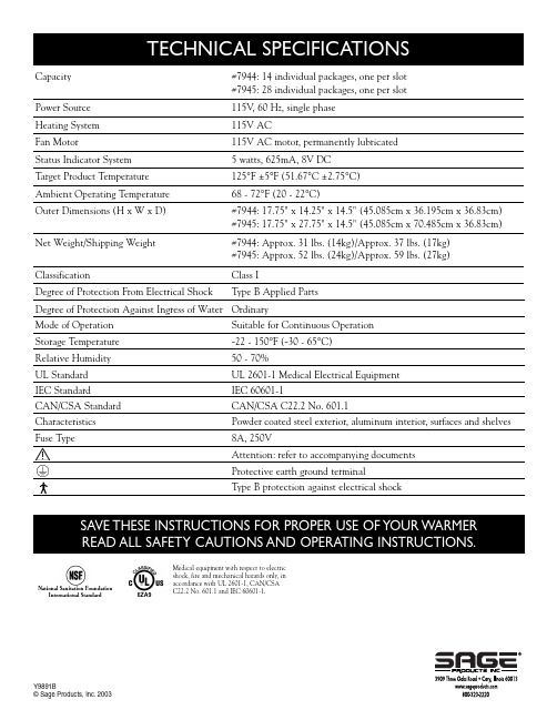
National Sanitation FoundationInternational StandardSAVE THESE INSTRUCTIONS FOR PROPER USE OF YOUR WARMERREAD ALL SAFETY CAUTIONS AND OPERATING INSTRUCTIONS.#7945: 28 individual packages, one per slot Capacity#7944: 14 individual packages, one per slot Power Source115V , 60 Hz, single phase Heating System115V AC Fan Motor115V AC motor, permanently lubricated Status Indicator System5 watts, 625mA, 8V DC Target Product Temperature125°F ±5°F (51.67°C ±2.75°C)Ambient Operating Temperature68 - 72°F (20 - 22°C)Outer Dimensions (H x W x D)#7944: 17.75" x 14.25" x 14.5" (45.085cm x 36.195cm x 36.83cm) #7945: 17.75" x 27.75" x 14.5" (45.085cm x 70.485cm x 36.83cm) Degree of Protection From Electrical ShockType B Applied Parts ClassificationClass I Y9891B©Sage Products, Inc.2003Degree of Protection Against Ingress of Water OrdinaryMode of OperationSuitable for Continuous Operation Storage Temperature-22 - 150°F (-30 - 65°C)Relative Humidity50 - 70%UL StandardUL 2601-1 Medical Electrical Equipment Type B protection against electrical shock 6ZA9Medical equipment with respect to electricshock, fire and mechanical hazards only, inaccordance with UL 2601-1, CAN/CSAC22.2 No. 601.1 and IEC Weight/Shipping Weight#7944: Approx. 31 lbs. (14kg)/Approx. 37 lbs. (17kg)#7945: Approx. 52 lbs. (24kg)/Approx. 59 lbs. (27kg)®Warmer Operating Instructions Model #7944 (14 count) • Model #7945 (28 count)For use with Comfort Personal Cleansing®brand bathing, incontinence and hair care products only.Please read and understand these instructions completely prior to operatingthe Comfort Personal Cleansing®Warmer.This warmer is to be used SOLELY for Sage Comfort Personal Cleansing®products. The warmer has beendesigned and safety tested to be used exclusively with Comfort Personal Cleansing products. ANY other use of the warmer by the facility, including but not limited to use with other bathing products, can result in overheating, fire or other hazardous conditions and is expressly forbidden.WARNING:To reduce the risk of fire, burns, electrical shock, or injury:1. Read all instructions before using this warmer.2. Grounding reliability can only be achieved when the equipment is connected to an equivalent receptacle marked“hospital only” or “hospital grade.”3.Install this warmer only in accordance with the installation instructions found in this manual.4. DO NOT cover or block any openings on this appliance.5. DO NOT tamper with or make any adjustments to the control panel, housings, safety switches, or any other partof the Comfort Personal Cleansing Warmer.6. DO NOT remove any panel or cover.7. DO NOT store or use this appliance outdoors. DO NOT use this product near water—for example, near a kitchensink, in a wet basement, or near a swimming pool.8. DO NOT use this warmer for any material other than Comfort Personal Cleansing products in accordancewith instructions on the label.9. DO NOT let the cord hang over edge of table or counter.10. This warmer is to be used by adults familiar with its operation and these safety instructions.11. DO NOT operate this appliance if it has a damaged cord or plug, if it is not working properly, or if it has beendamaged or dropped.12. DO NOT immerse cord or plug in water.13. Keep cord away from heated surfaces.14. The warmer is to be serviced only by qualified service personnel. If there are no external or user-serviceablefuses, contact Sage Products for repair or adjustment. If there are external or user-serviceable fuses, check them and replace if necessary. If new fuses do not correct the condition, or if fuses continue to blow, contact Sage Products for repair or adjustment.e this appliance only for its intended purpose as described in this manual. DO NOT use corrosive chemicalsor vapors in this appliance. This type of warmer is specifically designed to warm Comfort PersonalCleansing products. It is NOT designed for industrial or laboratory use. The use of corrosive chemicals in heating or cleaning will damage the appliance and may result in product failure.Your new Comfort Personal Cleansing®warmer is equipped with status indicators which are designed to provide information on the heating status of the packages in the unit. The status indicators allow you to know the difference between packages that have not been in the warmer long enough to reach the target temperature of 125°F (51.67°C) and those that have. It will also tell you which packages have been in the warmer for an extended period of time, so you can use those packages before others which have just been stocked that day—it is a prompt that helps you keep your Comfort Personal Cleansing products fresh. To activate the status indicators, place a package in a slot and the warmer does the rest. Here is a description of each of the three status indicator prompts:Immediately next to each slot is a set of three arrows with the messages “NOT READY,” “READY,” and “TAKE FIRST,” respectively.1.NOT READYThe red arrow and message that reads “NOT READY” indicates the package in this slot has not been in the warmer long enough to reach the target temperature. The red “NOT READY” arrow will remain lit for thetime it takes to heat the Comfort Personal Cleansing product (approximately 2 hours).2. READYThe green arrow and message that reads “READY” indicates the package in this slot has been in the warmer long enough to reach the target temperature and is ready for use.3. TAKE FIRSTThe blinking green arrow and message that reads “TAKE FIRST” indicates the package in this slot has been in the warmer for an extended period of time and should be used before other packages. This feature helps you use the cleansing products in your warmer in the order in which they were stocked. If more than a few packages ofa certain product type have the blinking “TAKE FIRST” arrow lit for an extended period of time, it may beappropriate to cut down on the number of slots of that product code and restock them with one of your higher usage products. If patient census is low and more than a few slots frequently indicate “TAKE FIRST,” it may be appropriate to leave a few slots empty until product usage increases.Testing has shown that an empty unit’s accessible interior metal surfaces—after a one hour stabilization period—will measure 125°±10°F (51.67°C ±5.5°C). This higher operating temperature is necessary to achieve desired Comfort Personal Cleansing product temperature (as measured inside the product) of 125°±5°F (51.67°C ±2.75°C) within two hours of product insertion.Additionally, the warmer is equipped with a protective device designed to turn the unit off in the event of overheating. The warmer will remain inoperable until it has cooled.Please refer to Comfort Personal Cleansing product packages for instructions, ingredients, warnings andother information.Examine Your WarmerUnpack warmer, remove all packing material and examine the unit for any damage such as dents, broken door latches, etc. Notify Sage Products immediately if warmer is damaged. DO NOT install or operate if warmer is damaged. Remove Protective Plastic FilmIf a plastic film has been wrapped around the warmer to protect the painted finish from scratching during shipping, please remove this plastic film prior to using the warmer (however, not all warmers have plastic film wrapping). Placement of Warmer1.Warmer must be placed on a flat, stable surface. For proper operation, the warmer must have sufficient airflow. Allow 3 inches (7.62cm) of space on both sides and back of the warmer and 1 inch (2.54cm) of space on top of the warmer. (Placing 2 of the 14 ct. warmers side by side is acceptable)a) DO NOT block air vent. If it is blocked during operation, the warmer may overheat.If the warmer overheats, a thermal safety device will turn the unit off. The warmer willremain inoperable until it has cooled.b) DO NOT place warmer near a hot, damp surface such as a gas or electric range.c) Be certain that power cord on the warmer can reach the electrical outlet.d) Be certain electrical outlet is not blocked by the warmer. Power cord must be able to be unpluggedwithout moving the warmer.Grounding InstructionsThis appliance must be grounded. In the event of an electrical short circuit, grounding reduces the risk of an electric shock by providing an escape wire for the electric current. This appliance is equipped with a cord having a grounded wire with a grounded plug. The plug must be plugged into an outlet that is properly installed and grounded.WARNING: Improper use of the grounding plug can result in a risk of electric shock.Consult a qualified electrician or service person if the grounding instructions are not completely understood, or if doubt exists as to whether the appliance is properly grounded.If it is necessary to use an extension cord, use only a three-slot receptacle that will accept the plug on the appliance. The marked rating of the extension cord should be equal to or greater than the electrical rating of the appliance. Wiring Requirements1.The warmer must be plugged into at least a 15-AMP, 115-VOLT,60-Hz GROUNDED OUTLET.Figure 1Where a standard two-prong outlet is encountered, it is the personalresponsibility and obligation of the user to have it replaced with aproperly grounded three-prong outlet (Figure 1).2. The warmer must be on a SEPARATE CIRCUIT. No other appliance should share the circuit with thewarmer. If it does, the branch circuit fuse may blow, or the circuit breaker may trip, or Comfort PersonalCleansing®products may warm slower than the times recommended.3. The VOLTAGE used must be the same as specified on the warmer (115V). Using a higher voltage may result in afire or other accident causing warmer damage. Using a lower voltage will cause slow heating. Sage Products is NOT responsible for damage resulting from the use of the warmer with other than specified voltage.This warmer is to be used SOLELY in connection with the use of Comfort Personal Cleansing products.The warmer has been designed and safety-tested to be used exclusively with Comfort Personal Cleansing products. ANY other use of the warmer by the facility, including but not limited to use with other bathing products, can resultin overheating, fire or other hazardous conditions and is expressly forbidden. Refer to individual packages of Comfort Personal Cleansing products for recommended heating times.General Use1. DO NOT tamper with or make any adjustments to the control panel, housings, safety switches, or any other partof the Comfort Personal Cleansing Warmer. Repairs should only be done by a qualified service person. Contact Sage Products for authorized service.2. If a fire occurs in the warmer, LEA VE DOOR(S)CLOSED. Disconnect the power cord, or shut off power at thefuse or circuit breaker panel.3. DO NOT store flammable materials next to, on top of, in or near the warmer. They could be a fire hazard.4. Your warmer is equipped with a protective device designed to turn the unit off in the event of overheating. Thewarmer will remain inoperable until it has cooled.CAUTION:If there is any indication cap or washcloths are excessively hot, do not use. Remember, gloves diminish your sensitivity to heat. Closely monitor heat level with infants, unresponsive or skin sensitive individuals. Caps/Baths are for individual use only.Examine the Comfort Personal Cleansing®Warmer before plugging in power cord. If any part appears damaged, do not use the warmer. Contact your Sage Products Representative.1. To install warmer,position unit on a sturdy, flat surface, such as a counter top or Comfort Personal Cleansing®cart. For proper grounding, plug cord into AC receptacle marked “hospital only” or “hospital grade.” Turn power switch on front panel to “on” position. The red light in the power switch should illuminate when switched to the “on” position.When power is turned on, the warmer goes through the following self-diagnostic tests:•All red “NOT READY” indicators flash three times.•All green “READY” indicators flash three times.•All green “TAKE FIRST” indicators flash three times.•Temperature indicator counts down.If no faults are found,LED’s will turn off if no products are present in warmer slots. If products are present, the LED’s for the filled slots will indicate “NOT READY.”If a fault condition exists, LED’s will not light up if product is present in warmer slots. Unused slots will indicate a “NOT READY” status. Discontinue use of the warmer unit and contact Sage Products.2. To stock warmer,open door(s) and fill slots with any combination of Comfort Personal Cleansing products—onepackage per slot. Place packages on shelves so they do not interfere with closing of door(s). Packages should be placed far enough back that they contact rear of shelves, but not beyond. Close warmer door(s). DO NOT place previously opened packages into warmer.3. Packages require approximately 2 hours to warm.Products are ready for use when the “READY” indicator isilluminated. To remove product for use, open door(s). Remove package(s). Close warmer door(s), making certain door(s) close completely.4. Replacement parts and service: Before performing any repairs or service on this warmer, contact Sage Products.5. Fuses: This warmer is equipped with two externally accessible fuses. Turn off and unplug the warmer beforeattempting to remove fuses. If the warmer stops running, check the fuses on the back side of the cabinet’s exterior. If a fuse is blown, replace it with another fuse of identical rating. If the new replacement fuse blows, contact Sage Products for further instructions.To replace fuse: Turn off and unplug unit. Find the round knob on the rear panel of the warmer cabinetlabeled “FUSE” and unscrew the fuse cover counterclockwise as indicated by the arrow on the fuse cover.Remove the fuse and replace it with an 8-Amp, 250-Volt (8A, 250V) fuse and replace the fuse holdercover. Plug the warmer into the 115V power outlet and turn power switch to the “on” position. If warmerwill not run, or does not run properly after replacing the fuse, call Sage Products for further direction.6. Memory Backup: This warmer is equipped with a 5-minute memory backup . It provides backup power to thestatus indicator system for a short period of time in the event that the power switch is shut off, or power cord is removed from the wall outlet. If power is interrupted, the status indicators will remember the status of all the packages in the warmer at that time and reinstate those settings when power is restored within 5 minutes.fort Personal Cleansing products: Refer to individual product package for instructions, ingredients,warnings and other information.Front View #7944 (14 count)#7945 (28 count)Side View Front View Side View16.TO REDUCE THE RISK OF FIRE:•Warm only Comfort Personal Cleansing®products.•Do not use to heat or store any other material or products.•If materials inside the warmer should ignite, keep the door(s) closed, turn the warmer off, and disconnect the power cord, or shut off power at the fuse or circuit breaker panel.•Do not operate the Comfort Personal Cleansing Warmer empty—always have some Comfort PersonalCleansing products in warmer when it is in use (it is not necessary to fill every slot).17.Do not store flammable materials in the proximity of the Comfort Personal Cleansing Warmer. It could be afire hazard.18.Equipment not suitable for use in the presence of a flammable anesthetic mixture with air, or with oxygen ornitrous oxide.19. The Comfort Personal Cleansing Warmer uses circulated warm air.20. The warmer should NOT be adjusted by anyone except properly qualified personnel. Contact Sage Products forauthorized service.1. Unplug the warmer before cleaning.2. Keep the inside of the warmer clean. If spatters or fluid adhere to walls, wipe with a damp cloth. Mild detergentmay be used if the warmer gets very dirty. The use of harsh detergent or abrasives is not recommended. NEVER clean the Comfort Personal Cleansing warmer with alcohol or solvent-based cleansers. Alcohol or solvents on acrylic door(s) or status indicator display columns can weaken and, in time, cause cracking of theseplastic components.3. The status indicator columns and center column must be removed to allow cleaning of the shelves and cabinetinterior. Remove the Phillips head screw located at the base of each column. Gently lower the column to disengage from the ceiling support. The columns may now be pulled forward, then lifted out to remove them from the warmer. Unplug the connectors at the base of the indicator columns. Gently place the removed column assemblies on a stable surface. The shelving may now be accessed. To remove the shelves, disengage the stand-offs and pull shelf forward. Wipe out cabinet interior and clean the shelves. Return all components to their original positions in the reverse order of disassembly. Be sure to replace the screws at the base of the columns.4. The outside warmer surfaces should be cleaned with a large, damp cloth. To prevent damage to the operating partsinside the warmer, water should not be allowed to seep into the ventilation openings or any other openings on the cabinet exterior. Use cloths that have been dampened with mild detergent solution only, but not so wet as to drip liquid or cause liquid to pool in warmer.5. If external electrical components become wet, including the display columns, power cord, power switch on front ofcabinet and external fuse access (if so equipped), clean with a soft, dry cloth and allow to air dry. DO NOT use harsh detergents or abrasives on any external components.6. Cleaning inside the warmer outer panels and inside the warmer base should be performed only by qualifiedservice personnel after taking precautions to drain all stored voltage potential. Contact Sage Products forauthorized service.。
驻车加热器使用说明书
库克斯曼驻车加热器CS5-H/Q1、C1使用说明书目录1.遥控器功能及按键使用说明··········2.显示屏显示说明···············2.设定加热器工作时间方法···········3.启动加热器·················4.中止加热器工作···············安装库克斯曼驻车加热器的理由:●寒冷的冬季,让您在上车前就能迅速预热发动机乘务仓,驱走严寒、自动除霜,改善驾乘环境,从此不需再用暖库;●预热发动机,大大减少低温启动带来的冷磨损。
发动机磨损很大一部分是由于冷启动造成的,研究表明每次冷启动对发动机造成的磨损相当于车辆正常行驶200公里。
所以安装驻车加热器能全面保护发动机,延长发动机的使用寿命;●节省燃油,与冷启动发动机预热相比,采用驻车加热器预热的耗油量更低;●启动、设定操作简便,三种启动方式供您选择:A遥控器启动:启动控制范围800米(无障碍状态),从5到50分钟设定加热时间;B定时器启动:24小时范围内,任意预设启动时间C移动电话启动:有移动电话信号覆盖的地方,可自由启动●世界先进技术,主要零部件均由德国供应商提供。
汽封加热器 说明书

汽封加热器说明书汽封加热器说明书1.产品概述1.1 产品名称:汽封加热器1.2 产品型号:-1.3 产品用途:用于加热汽封系统,提供稳定的工作温度,保证汽封的正常运行和寿命。
2.产品结构及组成2.1 主体结构:汽封加热器由外壳、加热元件、温控系统和安全保护装置组成。
2.2 外壳材质:不锈钢2.3 加热元件:采用优质镍铬合金电热棒2.4 温控系统:采用微电脑温控器,可精确控制加热器的工作温度。
2.5 安全保护装置:包括过热保护装置和漏电保护装置,确保使用安全。
3.使用方法3.1 将汽封加热器放置在所需加热的汽封系统上,确保加热器与汽封系统完全接触。
3.2 连接电源,并将温控器设定为所需的工作温度。
3.3 加热器将自动开始加热,当温度达到设定温度后会停止加热,保持恒温状态。
3.4 停止使用时,关闭电源并清理加热器表面的灰尘和污垢。
4.注意事项4.1 请勿长时间让加热器处于空载状态,以免损坏加热元件。
4.2 禁止将加热器浸入水中或任何液体中,以免发生漏电危险。
4.3 请勿在加热器周围摆放易燃物品,以免引起火灾。
4.4 使用过程中,如发现异常情况或故障,请立即停止使用并联系售后服务。
5.维护与保养5.1 定期检查加热器的外壳和连接线,松动部分及时拧紧。
5.2 清理加热器表面的灰尘和污垢,保持清洁。
5.3 维修和保养需由专业人员进行,切勿私自拆卸或修理。
附件:1.产品规格说明书2.温控器使用说明3.售后服务联系方式法律名词及注释:1.漏电保护装置:根据《电器安全法》的规定,漏电保护装置是一种用于保护人身安全和设备的装置,当电流泄漏到达特定值时,能够迅速切断电源,以防止触电事故的发生。
2.过热保护装置:过热保护装置是一种用于保护电器设备免受过热损坏的装置,当设备温度超过设定值时会自动切断电源,以保护设备的正常使用。
CHS高效火管蒸发燃气加热器用户说明书

MODELS CHS-85 through CHS-399User’s Information ManualCHS HIGH EFFICIENCY FIRE TUBE CONDENSING GAS BOILERThis appliance must be installed and serviced by a qualified in-staller or service technician. This appliance must be serviced and inspected annually when operating in normal residential ap-plications. Other applications (mercial or other more strenuous conditions) may require more frequent service and inspection. As the User of this equipment, you are responsible for ensuring maintenance is performed at the required intervals.It is also the User’s responsibility to ensure Vent and Combus-tion Air-inlet terminations are kept clear of obstructions.User Responsibilities:SAVE THESE INSTRUCTIONS:Installing Contractors, leave these instructions with the customer as it contains important information regarding annual inspection requirements, mainte-nance check lists, and shut down procedures. Affix instructions close or adjacent to the appliance.As the installing technician, it is your responsibility to ensure the installation is performed in accordance with the Installation and Operation Instructions as well as any applicable local or National installation codes. It is also your responsibility to inform the User/Owner of their obligation with respect to the above descrip-tion under “User Responsibilities”. Failure to follow this warning could result in fire, serious injury, or death.Installer Responsibilities:©Slant/Fin Corp. 2012 • 712 • PUBLICATION CHS-UIMCONTACT FOR SERVICE AND ASSISTANCEHeating Contractor:_______________________________________Phone__________________________________________Boiler Model #_______________________ Boiler Serial_________________________ Installation Date________________CHS User Information ManualCHS-85-3992Lighting / Shutting Down the ApplianceRead Before Proceeding - If you do not follow these instructions exactly, a fire or explosion may result causing property damage, serious injury or death.FOR YOUR SAFETY, READ BEFORE OPERATING _A) This appliance does not have a pilot. It is equipped with an ignition device which automatically lights the burner. Do not try to light the burner by hand.B) BEFORE OPERATING smell all around the appliance area for gas. Be sure to smell next to the floor because some gas is heavier than air and will settle on the floor. WHAT TO DO IF YOU SMELL GAS: • Do not try to light any appliance. • Do not touch any electric switch.• Do not use any phone in your building.• Immediately call your gas supplier from a neighbor's phone. Follow the gas supplier's instructions. • If you cannot reach your gas supplier, call the fire department.C) Use only your hand to turn the gas “shutoff” valve. Never use tools. If the handle will not turn by hand, don'ttry to repair it, call a qualified service technician. Force or attempted repair may result in a fire or explosion.D) Do not use this appliance if any part has been under water. Immediately call a qualified service technicianto inspect the appliance and to replace any part of the control system and any gas control which has been under water.OPERATING INSTRUCTIONS _1. STOP! Read the safety information above very carefully.2. Set the thermostat to lowest setting. Turn off all electric power to the appliance.3. This appliance does not have a pilot. It is equipped with an ignition device which automatically lights the burner. Do not try to light the burner by hand.4. Turn the manual gas valve to the OFF position. Remove front access panel.5. Wait five (5) minutes to clear out any gas. Then smell for gas, including near the floor. If you smell gas, STOP! Follow “B” in the safety information above. If you don't smell gas, go to the next step.6. Turn the manual gas valve ON. Wait an additional five (5) minutes smelling for gas.7. Replace the front access panel.8. Set thermostat to highest setting. Turn on all electric power to the appliance. 9. Ignition sequence is automatic. Combustion will occur after a brief fan purge.10. If ignition does not occur, follow the instructions “To Turn Off Gas To Appliance” and call your service technician or gas supplier.TO TURN OFF GAS TO THE APPLIANCE _1. STOP! Read the safety information above very carefully.2. Turn off all electric power to the appliance.3. Turn the manual gas valve to the OFF position.User InspectionUser inspections do not eliminate the need for an annual inspection by a qualified service technician. Routine visual inspections allow the user to spot potential problems that may affect unit operation or occupant safety.Periodic Inspection Checklist (recommended monthly)☐ 1. Remove the front access cover. Check inside the unit for leakage from plumbing, venting or condensate. ☐ 2. Plumbing - Check outside the unit for leaky joints, water stains, or pooling fluid on the floor.☐ 3. Venting - Inspect all indoor exhaust vent and combustion air-inlet pipes and examine them for cracks ormisaligned joints. Water dripping from unsealed vent pipe connections is an indication that flue gases are escaping. Check vent terminations and make sure they are free of debris and obstructions.☐ 4. Condensate - The condensate trap and drain should have clear fluid in it. Check that the condensate is notbacking up onto the floor or spilling into the bottom of the appliance cabinet.☐ 5. Contact a service technician immediately if there is any sign of leakage, either inside or outside the unit.CHS-85-399User Information Manual CHS3Should overheating occur or the gas supply fail to shut off, close the Manual Gas Shutoff valve to the appliance. Failure to follow instructions could result in explosion causingproperty damage, serious injury or death.Do not use this appliance if any part has been underwater. Immediately contact a qualified service technician to inspect the unit and replace any damaged components. Failure to followinstructions could result in explosion causing property damage, serious injury or death.Service Technician InspectionThis unit must be inspected at the beginning of every heating season by a qualified service technician.Annual Inspection Checklist☐ 1. Lighting is smooth and consistent, and the combustion fan is noise & vibration free. ☐ 2. The condensate drain freely flows, and is cleaned of sediment. ☐ 3. Relief Valve and air vents are not weeping.☐ 4. Low water cut off is tested and flushed (if applicable).☐ 5. Examine all venting for evidence of leaks. Ensure vent screens are cleaned and clear of debris. ☐ 6. Check the burner plate for signs of leaking.☐ 7. The combustion chamber must be inspected and if necessary cleaned (Refer to Annual Maintenance andInspection section in the appliance Installation and Operating Instructions).☐ 8. Listen for water flow noises indicating a drop in appliance water flow rate. The hydronic system may requireflushing to eliminate hard water scale.Crystalline Silica – Carefully read the warnings and handling instructions in the Installation and Operating Instruction for Refractory Ceramic Fibres before commencing any servicework in the combustion chamber.Replace any gaskets or insulation discs that show any signs of damage. Do not re-use. Failure to follow these instructions may result in fire, property damage or death.Allowing the appliance to operate with a dirty combustion chamber will adversely affect its operation and void the warranty. Failure to clean the heat exchanger on a frequency thatmatches the need of the application may result in fire, property damage, or death.SLANT/FIN CORPORATION, Greenvale, N.Y. 11548 • Phone: (516) 484-2600FAX: (516) 484-5921•Canada: Slant/Fin LTD/LTEE, Mississauga, Ontario。
NHZK713说明书2.0

1.概述1.1 简介:NHZK713型仪表采用先进的SMT技术,体积小巧,功能齐全。
标准的RS485(NHZK713)/RS232(NHZK713A)点对点通讯功能,可进行数据设定、仪表校准、配料控制等全部功能的操作;可校准的模拟量输出功能(4-20mA电流输出),可实现实时重量输出。
注:此说明书包括NHZK713系列仪表以下两种类型:●NHZK713:仪表通讯采用RS485通讯方式。
●NHZK713A:仪表通讯采用RS232通讯方式。
1.2 有关术语:●自重:能使称重传感器产生电压的承载器本身的重量。
●分度间距:指显示间距与信号倍数的比例,分度间距数值只能选择数值1、2、5中的某一个。
●激励电压:指由显示器提供用以驱动称重传感器的电压。
●过冲量:当快速和慢速继电器断电后,有些物料由于已离开供料槽,尚在半空中,这些物料会继续自由下落至秤的承载器上,这些自由下落的物料导致称重显示器的读数的平均增量,就是过冲量。
●过冲控制:当NHZK713系列仪表的读数大于或等于目标配料份量减去过冲量时,慢速配料继电器则自动断电。
●粗计量:大给料停止时,称量仓内物料重量(尚在空中的不算在内)与设定值之间的差值。
●测力与称重传感器:测力与称重传感器是一种将所受力或重量转换成电压的部件。
●传感器输出灵敏度:指从传感器输出的电压与激励电压的比例。
●最大量程:指为称重显示器设计(略去小数点后)的最大配料重量。
●倍数:倍数是用来确定小数点位置或加在读数后零的个数。
例如:如果读数为234 则:倍数显示器显示1023401234.1 23.4.01 2.34.001 .234.0001 .0234●分辨率:指最大量程与显示间距之比例。
●称量间距:指重量显示器对秤的承载器上单位标准重量变化所显示的数值。
●过冲量自动修正:过冲量自动修正公式为:过冲量(新值)=过冲量(旧值)-(目标配料份量-最终物料净重)/2。
此值的最大值为粗计量设定值,最小值为零。
汽气暖气机产品说明书

Form 50FT -1SB Replaces: New 50FT-1SBPrinted in U.S.A.3-00Catalog No. 515-169© Copyright 2000 Carrier Corporation • Syracuse, New York 1322150FT078,088,104HORIZONTAL SUPPLY AND RETURN SINGLE-PACKAGE COOLING UNITS CONSTANT/VARIABLE AIR VOLUME PRODUCT INTEGRATED CONTROLS CARRIER COMFORT NETWORK COMPATIBLE WITH INTEGRAL ECONOMIZER AND HIGH-CAPACITY MODULATING POWER EXHAUST—PERFORMANCE DATA —TYPICAL FIELD WIRING —CERTIFIED DIMENSION PRINTS —CERTIFIED ROOF CURB DIMENSION PRINTSDate:Supersedes:50FT078,088,104SINGLE-PACKAGE COOLING UNITS, WITH PRODUCT INTEGRATEDCONTROLS 50FTRev:JOB NAME:LOCATION:BUYER:BUYER P.O. #CARRIER #UNIT NUMBER:MODEL NUMBER:PERFORMANCE DATA CERTIFIED BY:DATE:DESCRIPTION50FT units are completely packaged, prewired and precharged cooling only units with PROD-UCT INTEGRATED CONTROLS. Units include integral economizer and high-capacity modu-lating power exhaust.The standard unit is factory-assembled, rated in accordance with ARI Standard 340/360, tested inaccordance with UL Standard 1995, and listed by ETL and ETL, Canada.50FT units are built for horizontal supply and return applications. Their waterproof constructionmakes them ideally suited for installation on the accessory roof curb or slab mounting.Units are either CONSTANT VOLUME or V ARIABLE AIR VOLUME depending on thefactory installed options selected.PRODUCT INTEGRATED CONTROL FEATURESSTANDARD CONTROL FUNCTIONSUnit compatible with CARRIER COMFORT NETWORK or stand-alone operation.Constant V olume or Variable Air V olume control.Six to 11 steps of capacity staging possible.Supply fan control based on occupancy schedule using 365-day electronic timeclock with holiday scheduling.Time schedule override through the space temperature sensor pro-vided with the unit.Compatible with 37H and 45 Series PIC terminals to form a Digital Air V olume system (DA V).Building pressurization control in conjunction with modulating power exhaust.Supply duct static pressure controlled through inlet guide vanes or field or factory supplied inverter.Head pressure control to –20° F. Head pressure controlled by satu-rated condensing temperature. Low ambient control utilizes Motormaster® II fan cycling.Lead-lag refrigeration system control to even out circuit run time. Self-diagnostic run test confirms control and component operation at unit commissioning. Self-diagnostic troubleshooting codes indi-cate the reason unit tripped to expedite unit repair. Codes expand to English Text.Building Purge Mode flushes building interior with outdoor air to remove contaminants before occupancy.Adaptive Optimal Start minimizes the amount of time and energy required before entering the Occupied mode.Unoccupied Mode Free Cooling — units will utilize free cooling whenever possible to maintain the unoccupied set point.Input/Output of data and monitoring of alarms can be done remotely using Building Supervisor, or at the unit using the acces-sory HSIO module.Delayed Mechanical Cooling — units will utilize cooling to cool the space 3 degrees below the occupied set point to delay the need for mechanical cooling.ADDITIONAL CONTROL FUNCTIONSProvides a discrete output with occupancy control for use as speci-fied by the customer.Controls a field installed humidifier using a 4 to 20 mA or 2 stage output. Requires accessory humidity sensor.Smoke Control functions (Pressurization, Evacuation, Smoke Purge, and Fire Shutdown) are provided through software. Termi-nals are provided to interface with field supplied smoke/fire panel. Provides a 4 to 20 mA output to proportional hot water control valve for field supplied hydronic heating coil (located external from the unit). Requires a field supplied freezestat to protect coil. Differential enthalpy control can be provided using field installed accessory return air enthalpy sensors.Economizer control field configurable to:—Maintain a minimum economizer set point position,OR—Maintain the minimum economizer position based on input from an IAQ sensor (field supplied 0 to 10 volt),OR—Maintain a constant CFM of outdoor air intake (Requires acces-sory Outdoor Air CFM package),OR—Look at all three above and maintain minimum economizer position based on the dominant parameter.2UNIT FEATURESStandard one-year warranty.Standard unit as factory-assembled is listed by ETL and ETL, Canada.Units are rated in accordance with ARI Standard 340/360. Integrated economizer system including solid-state enthalpy controls, spring return actuator, low-leak damper section, and bottom-entry out-door air hoods with serviceable permanent washable aluminum mesh filters.High-capacity modulating power exhaust system controlling to space pressure, with V ariable Frequency Drive and factory-installed outlet hoods with backdraft dampers.Semi-hermetic Carrier Carlyle compressors.Dual refrigeration circuits, pre-charged with R-22.Intertwined evaporator coils with TXVs.Crankcase heaters.Compressor protection includes high and low pressure cutouts. Cabinet made of pre-painted galvanized steel, weathertight construc-tion with 500-hr salt spray finish.Tuf-Skin Rx ™ anti-microbial insulation.Large hinged access doors.Duct flanges for connection of Supply and Return ductwork to unit side openings.Lifting lugs for overhead rigging.Sloped condensate pan.Two-inch pleated return air filters (30%).Single low-RPM supply fan with 2-in. deflection isolation springs under fan sled and fixed-speed fan drives matched to motor horsepower.High efficiency supply and exhaust fan motors (meet EPACT requirements).Circuit breaker protection for all power components, including com-pressors, supply fan motor, exhaust fan motors and control circuits. Condenser-fan motors are totally enclosed and internally protected 3-phase motors.115-volt and 24-volt control circuit.Single-point electric service entry.PERFORMANCE DATAUnit Weight_______________________________________Lbs COOLINGGross Total Capacity_______________________________Btuh Gross Sensible Capacity____________________________Btuh Compressor Power Input_____________________________kW Entering Dry Bulb________F Entering Wet Bulb _______F Outdoor Temp___________F Altitude_______________Ft HEATINGNO UNIT MOUNTED HEA T A V AILABLE Curb Weight ______________________________________Lbs FAN PERFORMANCESupply Fan Airflow________________________________CFM External Static Pressure____________________________in. wg Fan Speed________RPM Fan Power______________Bhp Supply Fan Motor___________________________________HP Exhaust Fan Airflow_______________________________CFM External Static Pressure____________________________in. wg Fan Speed________RPM Fan Power______________Bhp Exhaust Fan Motor_____________________________HP TotalELECTRICAL DATAPower Supply to Unit V olts Phase 60 Hertz Minimum Circuit Amps Maximum Overcurrent Protection AmpsOPTIONS AND ACCESSORIESFACTORY-INSTALLED OPTIONSInlet Guide VanesVariable Frequency DriveHigh Efficiency Motor with Matching DrivePremium Efficiency Motor with Matching DrivePremium Efficiency Exhaust Fan Motors with Matching Drives 65% Pleated Return Air FiltersCopper Condenser CoilPre-Coated Aluminum Fin Condenser CoilsE-Coated Aluminum Fin Condenser CoilE-Coated Copper Fin Condenser CoilHot Gas BypassNon-Fused Unit-Mounted DisconnectSpecial Factory Modifications:__________________________________________________________________________________________________FIELD-INSTALLED ACCESSORIESOptional 4-Year Extended Compressor WarrantyHSIO Keypad and Display Module (Required forInitial Start-Up)Roof Curb with Condenser End Support(Per NCRA Guidelines)Roof Curb to Enclose the Condenser SectionCondenser Coil GuardVFD Remote Display Module KitDifferential Enthalpy Control SensorSpace Sensor with Set Point Adjustment (CV Applications)Pressure Transducers and Suction Gas ThermostatsIAQ SensorOutdoor Air CFM PackageRelative Humidity Sensorx34TYPICAL FIELD WIRING DISCONNECT PER NEC212223111213EQUIP GNDFIELD POWER WIRING CONNECTIONSLEGEND FIELD CONTROL WIRINGTYPICAL SP ACE TEMPERA TURE SENSOR WIRINGEQUIP GND —Equipment Ground NEC —National Electrical CodeLEGEND *Constant Volume Applications Only.CCN COMMUNICA TIONS BUS WIRING TO OPTIONAL SP ACE SENSOR RJ11 CONNECTORCCN —Carrier Comfort Network COM —Communications GND —Ground SW —Switch T —T erminal TB —T erminal Block TH —Thermostat, HeatingField Wiring5C U T A L O N G D O T T E D L I N E C U T A L O N G D O T T E D L I N ECE R T IF I E D D I M E N S I O N P R I N T6C E R T I F I E D A C C E S S O R Y R O O F C U R B D I M E N S I O N P R I N T7C U T A L O N G D O T T E D L I N E C U T A L O N G D O T T E D L I N E C E R T I F I E D R O O F C U R B D I M E N S I O N P R I N T D I M E N S I O N S *(d e g r e e s a n d i n c h e s )U N I T L E V E L I N G T O L E R A N C E S *F r o m e d g e o f u n i t t o h o r i z o n t a l.A B D e g i n .D e g i n .1.02.0.50.75N O T E S :1.R o o f c u r b i s s h i p p e d d i s a s s e m b l e d .2.D i m e n s i o n s i n [] a r e m i l l i m e t e r s .3.R o o f c u r b : 14 g a . [V A 03-56] s te e l.R o of c u r b p a n s : 16g a . [V A 03-56] s t e e l.ACCESSORY ROOF CURB — 50FT078,088,104。
汽气暖气机说明书
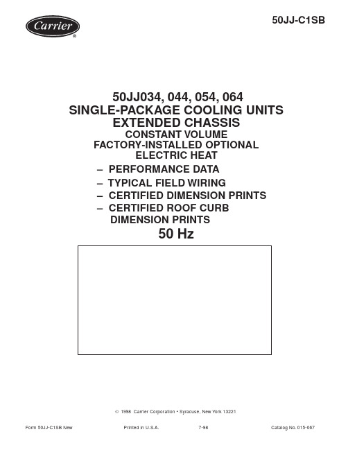
50JJ-C1SB© 1998 Carrier Corporation • Syracuse, New York 13221Form 50JJ-C1SB NewPrinted in U.S.A.7-98Catalog No. 015-06750JJ034, 044, 054, 064SINGLE-PACKAGE COOLING UNITSEXTENDED CHASSISCONSTANT VOLUMEFACTORY-INSTALLED OPTIONALELECTRIC HEAT– PERFORMANCE DATA – TYPICAL FIELD WIRING– CERTIFIED DIMENSION PRINTS – CERTIFIED ROOF CURB DIMENSION PRINTS50 Hz250JJ034, 044, 054, 064SINGLE-PACKAGE COOLING UNITS,EXTENDED CHASSIS CONSTANT VOLUMEFACTORY-INSTALLED OPTIONAL ELECTRIC HEAT50JJDESCRIPTION50JJ units are completely packaged, prewired and precharged cooling only units with electric heat available.50JJ units are built for BOTTOM supply and return applications. Their waterproof construction makes 50JJ units ideally suited for installation on the accessory roof curb.• 50JJ units have CONSTANT VOLUME controls. 28, 56 or 84 kW electric heat available.• Unit includes space and coil tracks downstream of the evaporator for field- or factory-installation of auxiliary devices.ELECTRICAL DATAPower Supply to Unit _________ Volts ________ Phase ________Hz Minimum Circuit Amps __________ Maximum Fuse Amps __________Unit Operating W eight ___________________COOLINGGross Total Cap. ___________ @ Condenser Air Temp ______________Gross Sensible Cap.__________ Compressor Power Input _____________Indoor Entering Air db _________________ wb _____________________Airflow ________________ Ext. Static Pressure ____________________Indoor Fan Motor Size _________________________________________Exhaust Fan Motor Size ________________________________________PERFORMANCE DATACurb Weight _________________________________________________HEATINGHeating Capacity:Stage 1____________________________________________________Stage 2____________________________________________________Heating Capacity Total ________________________________________FEATURESLarge hinged access doors.High efficiency indoor motors (supply and exhaust).Units are rated in accordance with ARI Standard 360Tuf-Skin Rx anti-microbial insulation (U.S.A. Standard).Sloped condensate pan.115-volt and 24-volt control circuit.Single-point electric service entry.51 mm (2-in.) disposable-type return air filters.Manual adjustable outside air intake for up to 25% outside air.Evaporator fan motors are protected by circuit breakers.Cabinet made of prepainted galvanized steel.Semi-heretic Carrier pressor protection includes high- and low-pressure cutouts.Lifting lugs.Evaporator-fan motors are protected by circuit breakers.Dual refrigeration circuits.Condenser-fan motors are internally protected.Crankcase heaters.Low outdoor temperature cooling operation to 7.2˚C (45˚F) as standard.Circuit breaker protection for all power components.Two-stage cooling.Single low rpm supply fan with 51 mm (2 in.) deflection springs Two-stage heating (option).under fan sled.OPTIONS AND ACCESSORIESFACTORY-INSTALLED OPTIONS (FIOP)u Integrated economizer with low leak dampers and spring return motor u Pleated filters (30%) 51 mm. (2 in.)u Bag filters with prefilters (90%)u Barometric reliefu Constant volume power exhaust u 100% modulating power exhaust u Electric heatu Copper condenser coilu Pre-coated Al-fin condenser coil u Non-fused unit mounted disconnect u Hot gas bypassFIELD-INSTALLED ACCESSORIESu Roof curb with condenser end support (50, 60 ton)u Roof curb to enclose the condenser section (50, 60 ton)u Roof curb with full perimeter support (30, 40 ton)u Barometric reliefu 100% modulating power exhaust u Electric heatu Condenser hail guard u Compressor unloadersu Motormaster ® head pressure control u Thermostat and subbase:e t a D :s e d e s r e p u S :v e R :E M A N B O J :N O I T A C O L :R E Y U B #.O .P R E Y U B #R E I R R A C :R E B M U N T I N U :R E B M U N L E D O M :Y B D E I F I T R E C A T A D E C N A M R O F R E P :E T A D3- - - - - - - - - - - - - - - - - - - - - - - - - - - - - - - - - - - - - - - - - - - - - - - - - - - - - - - - - - - - - - - - - - - - - - - - - - - - - - - - - - - - - - - - - - - - - - - - - - - - - - - - - - -C U T A L O N GD O T TE D L I N EC U T A L O N GD O T TE D L I N ETYPICAL FIELD WIRINGFIELD POWER WIRING CONNECTIONSFIELD CONTROL THERMOSTA T WIRINGLEGENDEQUIP GND –Equipment GroundLOW-VOLTAGE TERMINAL BLOCKIN UNIT CONTROL BLOCK (P1)EX W2W1Y2Y1G C RTHERMOSTAT/ SUBBASEXW2W1Y2Y1GCRHRCDISCONNECT PER LOCAL CODES212223111213EQUIP GND4。
艾莫斯煤气加热器说明书

EN G L I S HE S P A —O LF R A N ÇA I SPrinted in ChinaSIZE AND CAPACITY OF PROPANENOTE: Chart above shows number of 100 pound tanks needed to operate this heater at a given temperature.Less gas is vaporized at lowertemperatures. You may need two or more 100 pound tanks, or one larger tank in colder weather. Your localpropane gas dealer will help you select the proper supply system.General Safety InformationMake sure you read and thoroughly understand these safety and operating instructions. Keep these instructions for future reference. They are your guides to safe and proper operation of this heater.Indicates an imminentlyhazardous situation which, if not avoided, WILL result in death or serious injury.Indicates a potentiallyhazardous situation which, if notavoided, COULD result in death or seriousinjury.Indicates a potentiallyhazardous situation which, if not avoided, MAY result in minor or moderate injury.Always turn off heater at controlknob and then close LP cylinder when not Consumer: Retain this manual for future reference.Dyna-Glo ®Delux Propane Gas-Fired Radiant HeaterPlease read and save these instructions. Read carefully before attempting to assemble, install, operate or maintain the product described. Protect yourself andothers by observing all safety information. Failure to comply with instructions could result in personal injury and/or property damage! Retain instructions for future reference.DescriptionDyna-Glo Delux Model RA125LPDGD heater is a 125,000 BTU/Hr construction heater.This heater uses propane gas for combustion. It is primarily intended fortemporary heating of well-ventilated buildings under construction, alteration or repair. This heater should be utilized in sheltered, well-ventilated areas, but never in occupied dwellings.Dimensions L x W x H (in.)RA125LPDGD 50,000 to 5.77 lbs/hr 11” W.C.Min. 5 psi0.19“20.3 (heater) 16.3 x16.3 x 29.8 125,000Max. Bottle PressureFuel Type – Propane OnlyIgnition Type – P iezoMinimum Operating Temp. – -20°F (-29°C)SpecificationsFigure 1 – ModelUnpacking1. Remove heater, accessories and all hardware from the shipping carton. NOTE: Save the box and packaging materials for future use. Afterunpacking unit, inspect carefully for anydamage that may have occurred during transit. Check for loose, missing ordamaged parts. Shipping damage claim must be filed with carrier.GHP Group, Inc.8280 Austin AvenueMorton Grove, IL 60053CSA 2.14b-2009, ANS Z83.7b-2009 Construction HeaterC USRev 2011-01-282General Safety Information1. This heater has been designed as a construction heater in accordance with CSA2.14b-2009, ANS Z83.7b-2009. Other standards govern the use of fuel, gases and heating products for specific uses. Your local authority can inform you of these. The primary purpose of these construction heaters are to provide temporary heating of buildings under construction, alteration, orrepair. When properly used, the heater provides safe economical heating.Products of combustion are vented into the heated area. 2. Keep solid combustibles, such asbuilding materials, paper or cardboard a safe distance away from the heateras recommended by the instructions in this manual (at least 6 feet away from sides and 5 feet from top of heater).Never use the heater in spaces which do ormay contain volatile or airborne combustibles or products such asgasoline, solvents, paint thinner, dust particles, or unknown chemicals.3. This heater is hot when in use. To avoid burns, do not let bare skin touch hot surfaces. Do not move heater when in use OR for at least 35 minutes after using.4. Keep combustible materials, such as furniture, pillow, bedding, papers, clothes and curtains at least 6 feet away from sides and 5 feet from top of this heater.Carbon Monoxide poisoning may leadto death! Some people are more affected by carbon monoxide than others. Early signs of carbon monoxide poisoning resemble the flu, with headaches, dizziness, and/or nausea. If you have these signs, the heater may not beoperating properly or the area may not be sufficiently ventilated. Get fresh air at once! Have heater serviced.5. Do not operate any heater with a damaged regulator or after the heater malfunctions, or has been dropped or damaged in any manner. Return heater to an authorized service facility for examination, or mechanical adjustment, or repair.6. This heater should be utilized in sheltered, well-ventilated areas, but never in occupied dwellings, in living areas or sleeping areas.7. Do not use this heater in a residential or household area. If stored indoors, detach and leave the LP cylinder outdoors.8. Never replace the regulator with any regulator other than the factory suggested replacement.9. Do not insert or allow any foreign objects to enter any ventilation or exhaust opening as this may cause a fire, or damage to the heater.Carefully install and always use great carewhen operating this heater. Be sure to research and follow all local ordinances and codes. In the absence of local codes, with the Standard for the Storage and Handling of Liquefied Petroleum Gases, ANSI/NFPA 58 and the Natural Gas and Propane Installation Code, CSA B149.1. The heater is designed and approved for use as a construction heater inaccordance with Standard CSA 2.14b-2009, ANS Z83.7b-2009.CHECK WITH YOUR LOCAL FIRE SAFETY AUTHORITY IF YOU HAVE QUESTIONS ABOUT APPLICATIONS. Other standards govern the use of fuel gases and heat producing products in specific applications. Your local authority can advise you about these.California Proposition 65 Warning: Fuels used in gas or oil fired appliances and the products of combustion of such fuels, contain chemicals known to the State of California to cause cancer, birth defects or other reproductive harm. This product contains chemicals, including lead and lead compounds, known to the state of California to cause cancer, birth defects or other reproductive harm. Wash hands after handling.Never let children operate or allowednear any heater. Never leave heater operating and unattended.Dyna-Glo ®Delux Propane Gas-Fired Radiant HeaterFor Technical Support or Troubleshooting, Call: 1-877-447-4768, 8:30 am - 4:30 pm CST 3G L I S HGeneral Safety Information (Continued)10. Use this heater only as described in this manual. Any other use not recommended by the manufacturer may cause a fire or injury to persons. 11. Provide adequate ventilation. Beforeusing heater, provide at least a 3.0 square foot opening of fresh, outside air for every 100,000 BTU/Hr rating. 12. Do not modify or alter this heater inany way or operate any heater that has been modified from its original state.13. It is hard to anticipate every use which may be made of the heater. Check with your local fire safety authority if you have any questions about heater application.14. Be sure heater is on a solid and level surface.Propane Gas: Propane gas is odorless. An odor-making agent is added topropane gas. The odor helps you detect a propane gas leak. However, this odor may fade in time. Propane gas may be present in the area even though no odor is detected.15. Use only propane gas. Do not attempt to use natural gas.16. Keep appliance clear and free from combustible materials, gasoline, paint thinner, and other flammable vapors and liquids. Dust is com-bustible. Do not use heaters in areas with high dust content. 17. Check heater for damage before eachuse. Do not use damaged heater.Minimum heater clearance from combustibles:Sides: 6 feet Top: 5 feet Floor: Combustible - Not for use on finished floors18. The heater, other than a heaterwith an integral propane gas cylinder, must be located atleast (i) 6 ft. (1.83 m) in the U.S.; or (ii) 10 ft. (3 m) in Canada, from any propane gas cylinder.19. The propane cylinder supply systemmust be arranged to provide for vapor withdrawal from the operating cylinder.20. Blower or radiant type heaters shallnot be directed toward any propane gas cylinder within 20 feet (6 m).21. Check hose before each use of heater. Do not use if hose is cut or damaged. Replace with hose specified by manufacturer.22. The heater is not intended for use on finished floors. Warping or other damage may occur.23. Place heater away from any breezes or drafts. Keep away from dripping water or rain.24. Keep small children and animals away from the heater.25. Always wear gloves when handling the heater to prevent injury.26. Never attach ductwork to heater. 27. Use only original replacement parts.This heater must use design specific parts. Do not substitute or use generic parts. Improper replacement parts could cause serious or fatal injury.Assembly1. Provide propane gas supply only.2. Connect heater to a proper gas supplyusing the supplied regulator, and turn knob on LP cylinder on.3. Wait 5 minutes for any gas to clear.Smell for gas; if you do not smell gas,heater is ready to operate.Never use an open flame to check for aleak. Apply 50/50 mixture of liquid soap and water to all joints. Bubbles forming show a leak. Correct all leaks at once.OperationThis heater should only be used with a tank that has a vapor withdrawal system. Refer to the Standard of Storage and Handling of Liquefied Petroleum Gas, ANSI/NFPA 58, Chapter 5. Your local fire department or library will have this information.TO START HEATER1. Follow all of the safety, ventilation and installation instructions previously noted in this manual.2. Always be sure to place the heater on a stable and level surface while the heater is in operation. Be sure that no strong winds blow into the ends of theheater.3. Turn control knob clockwise to OFF position.4. Turn LP gas supply valve on.5. Depress heater control knob and turn counterclockwise to (IGN) LOW position to light burner.Model RA125LPDGDDyna-Glo Delux Operating Instructions and Parts Manual Figure 2 – Control KnobOperation (Continued)6. If burner does not light, turn heater control knob to OFF position and repeat step 5. Keep control knob depressed for approximately 10 to 15 seconds, then release control knob.7. If burner flame goes out, wait 5 minutes then repeat steps 5 and 6. 8. With burner operating, the control knob may be turned counterclockwise to desired heating level between LOW, MED, and HIGH.TO CONNECT OR DISCONNECT PROPANE TANKTurn heater gas valve knob and gas tank valve to OFF position.To connect gas line fitting to propane tank valve, turn fitting COUNTER-CLOCKWISE.To disconnect, turn fitting CLOCKWISE. Protect this fitting when disconnected from tank.LEAK CHECKING1. With heater gas valve knob still inOFF position, turn ON tank valve andcheck for leaks with soap solution.Check all connections with a 50/50soap and water solution to be surethey are tight and leak proof. Neveruse a flame to check for gas leaks.2. The installation of your heater mustmeet all local codes and/or gas utilityrequirements, or in the absence oflocal codes, with the National FuelCode ANSI Z223.1.TO SHUT DOWN HEATER1. Firmly close the propane gas supplyvalve.2. Shut off the main burner valve, beingsure to wear a glove for protection.Turn the main burner handle all theway to the OFF position.TO RESTART HEATER1. Wait five minutes for heater to cool.2. Follow steps in TO START HEATERsection.Running heaterbelow specified gaspressure may cause flashback. Duringflashback, the burner flame is mostlyyellow. The flame will burn inside theburner tube causing a roaring noise. Ifflashback occurs, turn heater off. Afterburner tube cools off, restart heater.VENTILATIONA three square footopening of freshoutside air for each 100,000 BTU / Hr ofheater output must be provided to operateeach heater safely. If the proper ventilationair is not provided, carbon monoxidepoisoning can occur. Always be sure thatthe proper ventilation is being providedbefore starting this heater.FRESH OUTSIDE AIR OPENINGREQUIREMENTSHeater size Square foot opening125,000 BTU3.5Read and understandall of the warnings inthe General Safety Information pages ofthis manual. They are essential to thesafe operation of this heater. Be sure tofollow all local codes when operating thisheater.Be sure to leak testall fittings and pipeconnections after installation or repairs.Use a 50/50 mixture of liquid dish soapand water. Bubbles forming reveal a leak.You must repair all leaks at once!Never attempt toservice heater while itis connected to propane supply, operating orhot. Severe burns can occur.1. Always keep heater clea n. The flowof combustion and ventilation aircannot be obstructed.Dyna-Glo® Delux Propane Gas-Fired Radiant HeaterFigure 3 – RA125LPDGD Part IdentificationFor Technical Support or Troubleshooting, Call: 1-877-447-4768, 8:30 am - 4:30 pm CST 45E N G L I S HModel RA125LPDGDSymptomPossible Cause(s)Corrective ActionBurner fails to lightBurner lights but goes out when automatic control valve button is releasedBurn rate is low, emitter does not glow Flames are extremely low and coming from emitter 1. More warm-up time needed 2. Gas pressure is low3. Thermocouple loose or in need of replacement4. Automatic control valve in need of replacement1. Main burner valve not completely open2. Clogged gas orifice3. Low gas pressure4. Low gas supply1. Main burner valve not fully open2. Plugged gas orifices3. Low gas pressure4. Low fuel supplyUnit has been connected to a natural gas supply instead of propane gas1. Relight, holding control valve button in for 45 seconds2. Inspect propane gas supply3. Tighten, reconnect or replace thermocouple4. Replace automatic control valve 1. Completely open main burner valve by turning control knob to HIGH position 2. Replace gas orifice3. Check gas supply, regulator function4. Consult gas supplier or replace tank 1. Fully open main burner valve by turning control knob towards HIGH position until it stops 2. Replace gas orifice3. Check gas supply, regulator output4. Consult gas supplier or replace tank Check gas source and replace with propane gas supplyTroubleshooting ChartDyna-Glo Delux Operating Instructions and Parts Manual6For Repair Parts, call 1-877-447-4768Please provide following information:-Model number-Serial number (if any)-Part description and number as shown in parts listFigure 4 – Repair Parts Illustration for Propane Gas-Fired Radiant HeaterFor Technical Support or Troubleshooting, Call: 1-877-447-4768, 8:30 am - 4:30 pm CST 7Model RA125LPDGDDyna-Glo Delux Operating Instructions and Parts Manual Repair Parts List for Propane Gas-Fired Radiant Heater1Top Cover 5002854 1 2 Guard 2315528 1 3 Emitter 2315519 1 4 N ozzle 2315522 1 5 N ozzle Connector 2315545 1 6 N ozzle N ut2315546 1 7 Main Gas Tubing Assy (LPG) 2315640 1 8 N ozzle Bracket 2315517 1 9 Flame Shield 2315642 2 10 Thermocouple 2201584 1 11 Spark Plug2201583 1 12 Thermocouple Holder 2315520 1 13 Base5002851 1 14 Control Knob 2101451 1 15 Control Valve 5050685 1 16 Fitting2304948 2 17 Tubing Inlet Assy (LPG) 2315525 1 18 Connector Bracket 2315526 1 19 LPG Inlet Connector 2315527 1 20 Hose5002721 1 21 Regulator 5002758 1。
汽轮机自密封汽封系统说明书

汽轮机自密封汽封系统说明书1概述汽轮机汽封系统的主要作用是为了防止蒸汽沿高压缸轴端向外泄漏,甚至窜入轴承箱致使润滑油中进水:同时防止空气通过低压轴端漏入低压缸而破坏机组的真空。
本机组汽封系统采用自密封汽封系统,即在机组正常运行时,由高压缸轴端汽封的漏汽经喷水减温后作为低压轴端汽封供汽的汽轮机汽封系统。
多余漏汽经溢流站溢流至排汽装置。
在机组启动,停机或低负荷运行阶段,汽封供汽由外来蒸汽提供。
该汽封系统从机组启动到满负荷运行,全过程均能按机组汽封供汽要求自动进行切换。
自密封汽封系统具有简单、安全、可靠、工况适应性好等特点。
2系统组成及主要设备该系统由轴端汽封的供汽、漏汽管路,高压主汽阀和主汽调节阀的阀杆漏汽管路,中压联合汽阀的阀杆漏汽管路以及相关设备组成。
本轴封供汽采用二阀系统,即在汽轮机所有运行工况下,供汽压力通过二个调节阀即高压供汽调节阀和溢流调节阀来控制,使汽轮机在任何运行工况下均自动保持供汽母管中设定的蒸汽压力。
机组启动或低负荷运行时由高压蒸汽经高压气源供汽站调节阀,进入自密封系统。
上述二个调节阀及其前后截止阀(或闸阀)和必需的旁路阀组成二个压力控制站。
此外,为满足低压缸轴封供汽温度要求,在低压轴封供汽母管上设置了一台喷水减温器,通过温度控制站控制其喷水量,从而实现减温后的蒸汽满足低压轴封供汽要求。
该系统所有调节阀执行机构均为气动型式,由DCS控制。
调节阀及执行机构均采用进口件,性能稳定,运行可靠。
为保证高压气源供汽站在机组正常运行中始终处于热备用状态,特在调节阀前设有带节流孔板的旁路。
机组正常运行时,汽封供汽母管中蒸汽经带节流孔板的旁路进入压力控制站,使之保持热备用状态。
本系统还设置一台JQ-80-3型汽封加热器及两台轴封风机(其中一台备用),用于抽出最后一段轴封腔室漏汽(或气),并维持该腔室微负压运行。
为了防止杂质进入轴封,各供汽支管上设有Y型蒸汽过滤器。
系统供汽母管还设有一只安全阀,安全阀整定压力为0.3MPa(a),可防止供汽压力过高而危及机组安全。
汽封加热器说明书

汽封加热器-说明书————————————————————————————————作者: ————————————————————————————————日期:JQ-46-4汽封加热器说明书南京汽轮电机(集团)有限责任公司编制谌开荣2012-4-23校核王强2012-4-24审核查小军2012-4-26会签刘小平2012-4-27标准审查郝思军2012.4.27审定批准ﻬ目次1.汽封加热器的作用32.技术规范33.汽封加热器的结构34.汽封加热器的监视仪表45.汽封加热器的连接方式 56.汽封加热器的运行及维护57.附图61.1汽封加热器排气口与轴封抽风机相连建立0.95ata的微弱真空,使汽轮机轴封及阀杆漏入的蒸汽和空气流入汽封加热器,而不致渗入轴承污染润滑油或在厂房空间扩散,保证了机组的安全运行。
1.2回收汽轮机轴封及阀杆漏入的蒸汽加热凝结水或补给水,提高了电厂的热循环效率。
2技术规范型号ﻩJQ-46-4流程 4换热面积(m2)46ﻩ冷却水量(t/h)ﻩ60最小水量(t/h)50管程设计压力(MPa)ﻩ2.5试验压力(MPa) 3.75(管程)0.2(壳程)冷却水速(m/s)ﻩ1.1冷却管材料TP304冷却管规格φ14×0.7×2242冷却管数量(根) 488汽封加热器净重(t) 1.1水阻(kPa)20汽封加热器为表面式换热器,卧式结构,由前、后水室及壳体组成,其结构形式见附图。
3.1壳体壳体由外壳、前后管板、支承板、管系、支撑板等组成。
外壳由钢板卷制焊接而成,呈圆筒形,两端与管板相焊。
管板由Q235-A厚钢板制成,前、后管板上各钻管孔488个。
冷却管采用不锈钢管,与管板的连接形式为强度焊加贴胀。
外壳内焊有五块支承板,缺口朝上的支承板底部开有一个通液口,便于凝结水流出。
汽封加热器由壳体下部的两个支撑板固定在基础上,靠近进出水端的支撑板为死点,另一个支撑板能保证汽封加热器自由膨胀。
QJR气体加热装置使用说明书

QJR-F气体加热装置使用说明书QJR-F GAS HEATER INSTRUCTION BOOK扬州伊华科技有限公司YANG ZHOU YIHUA SCIENCE TECHNIC CO.,LTD目 录CONTENTS1 概述 GENERAL ..............................................................................................................................2 2 QJR 装置组成与特点 COMPONENTS AND FEATURES ...........................................................3 3 技术参数 TECHNICAL DATE .....................................................................................................4 4 安装 INSTALLATION ..................................................................................................................5 5 使用与维护 OPERATION AND MAINTENANCE ....................................................................... 5 6产品保修期 GUARANTEE ............................................................................................................ 7 7 2CO 气体用量2CO QUANTITY REQUIRMENT .......................................................................... 7 8 主要配件明细表MIAN COMPONENTS .................................................................................... 10 9 外型尺寸安装图 HEATER OUTLINE ..................................................................................... 11 10 电气原理图 ELECTRIC SCHEMATIC ..................................................................................... 12 11 气体加热器管道连接图 GAS HEATER PIPING .. (13)1 概述GENERALQJR系列隔爆型气体加热装置是通过红外加热器给流动气体加热的一种装置。
昆腾直喷式燃气热水暖气机用户指南说明书
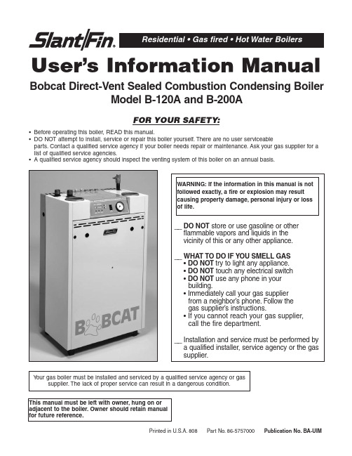
User’s Information ManualBobcat Direct-Vent Sealed Combustion Condensing BoilerModel B-120A and B-200A•Before operating this boiler, READ this manual.•DO NOT attempt to install, service or repair this boiler yourself.There are no user serviceableparts.Contact a qualified service agency if your boiler needs repair or maintenance.Ask your gas supplier for a list of qualified service agencies.•A qualified service agency should inspect the venting system of this boiler on an annual basis.Printed in U.S.A.808 Part No.86-5757000Publication No.BA-UIMFigure 1.Location and identification of parts.(model 120A shown)INSPECTIONY our boiler and heating system will last an indefinitely long time at full efficiency, if it is inspected regularly and is kept in good repair and adjustment.Y ou, the user, should make regular inspections, and report any problems to your service agency.At regular intervals, you should have that agency inspect the system and make repair adjustments as necessary.What you and the service agency should do is listed below.Contact your gas supplier for a list of qualified service and repair agencies.USER INSPECTIONThe user should make the following inspections at least once each month during the heating season and once just before cold weather starts.Bobcat B-120 and B-200 boil-ers may be installed and vented either as direct-vent boil-er, which all air for combustion is obtained directly from outside through the air intake piping or as non-direct-vent boiler, which all air for combustion is taken from inside the boiler room.T ypical direct-vent installations are shown on Figures 2 and 3.Non-direct-vent installation is shown on Figures 4, 5 and 6.1.VENTING AND AIR INTAKE SYSTEM REGULAR INSPECTIONInspect the system regularly for condensation, corrosion, sagging and/or physical damage.A qualified professional should service the boiler annually and include such an inspection at that time.The homeowner should look over the system monthly for damage, water stains, any signs of rust, other corrosions or separation of the vent and air intake piping (if direct-vent).Should an inspection turn up signs of condensation, corrosion, sagging or damage, the boiler should be shut down immediately and the condition should be corrected by a qualified professional.If the boiler is vented horizontally through the wall, the outside termination, louvers and screen should be checked for any debris blocking the opening and cleaned as required.A I RI NT AK EL O U VE RS3”DIA.AIR INT AKE PIPE3”DIA.VENT PIPEOUTSIDEWALLVENTTERMINA TIONOUTSIDETERMINATIONPANELFigure 2.Direct vent,sidewall venting illustration.VENTTERMINATIONAIR INTAKE 3” DIA.VENT PIPE3”DIA.AIR INTAKEPIPEFigure 3.Direct vent,venting and air intakethrough a roof.Figure 4.Non-direct vent,sidewall venting.Figure 5.Non-direct vent,venting through the roof.Figure 6.Non-direct vent,utilizing an existing chimney as a chase.2.CONDENSATE REMOVAL SYSTEMThe Bobcat B-120 and B-200 boilers are equipped with a built-in condensation drain and trap.The trap must be filled with water.DO NOT operate the boiler without fill-ing the trap with water to prevent flue gas discharge into space.Periodic inspection should be made of this assembly for deterioration of the tubing and to insure that the trap is not plugged.If it is plugged or appears to have excessive sediment in it, it should be removed from the drain assembly,straightened out to clear the obstruction, reformed, filled with water and reinstalled as before.(See Figure 7).Leave the top of the condensate drain tee open, to act as a vacuum breaker.Do not allow any part of the condensate removal system to be exposed to freezing temperatures, or any other conditions that could cause blockage.If a neutralizing system is installed, the filter medium will require periodic changing, to ensure it’s effectiveness.Refer to the neutralizing unit’s manufacturers instruc-tions,if available, or change the medium on an annual basis.3.PIPING INSPECTIONLook at all water piping.There should be no leaks or signs of leaks at any pipe joints or around the boiler.4.SYSTEM WATER PRESSURE INSPECTION The boiler water pressure is indicated on the pressure gage (See Figure 1 for location).The boiler water outlet temperature is normally indicated on the temperature display (See Figure 1 for location and Figure 9 for digits illustration).For most installations, it should indicateabout 12 to 15 psi pressure when temperature is about 70 to 100F and from 15 psi to 25 psi when temperature is up to 195˚F .FOR YOUR SYSTEM, there is one correct pressure for each temperature.ASK YOURINST ALLER OR SERVICEPERSON TO EXPLAIN AND SHOW YOU.Learn what normal pressure to look for.If pressure increases from normal, the relief valve will open to relieve the pressure.Call your service organiza-tion if pressures are higher or lower than normal, and if the relief valve spills water.Repair or adjustment is needed.5.UNUSUAL NOISEStand near the boiler and look and listen.As the burner start and shut off, there should be no unusual noise.6.BOILER ROOM AIR SUPPLYAmple boiler room fresh air is required for combustion (non-direct vent installation) and ventilation (direct-vent installation).Check air vents for continues positive supply of air as required.Air needs are greatest in cold weather if boiler installation is non-direct vent method.Air vents must be open and free of obstruction.Warning:The flow of combustion and ventilating air to theboiler should not be obstructed.Warning:If you find any problem during your inspection, callfor service immediately.Figure 7.Condensate disposal systemCONDENSATE TRAP ,FILLED WITH WATERDRAIN VACUUM BREAKER, LEAVE OPENNEUTRALIZING UNIT(IF REQUIRED)PLASTIC TUBINGCONDENSATE PUMP(IF REQUIRED)DRAIN INSIDE BUILDINGRemoving Jacket Front Panel1.T urn black screws 1⁄4turn to open position.2.Remove front panel.T o replace the panel, reverse procedure.INTEGRATED BOILER CONTROLThe integrated boiler control monitors the status of the room thermostat, high limit switch, low water cutoff (if installed), water inlet and outlet sensors, flue gas sensor and flame sensor.It controls the operation of the circula-tor, combustion blower, gas valve and spark ignitor.The boiler control also determines the sequence of operation and timing for pre and post purge periods, trial for ignition and lock out.The control display board provides information on boiler operation on a mode and temperature display and can be viewed, programmed and reset with specific push buttons. Diagnostic information is also provided on the display, to help determine the cause of boiler failure.(See Figure 9). BOILER CONTROL AND DISPLAY FEATURES(See Figure 9)A.BOILER OPERATION STATUS:“Mode Display”shows status of boiler operation.(See T able 1).B.VIEW AND CHANGING TEMPERATURES:Settingboiler supply water temperature and water tanktemperatures (See T able 2).Press “Select”button for viewing following differentmodes on “Mode Display”1.While “c”is blinking, boiler supply watertemperature for space heating may be set todesired temperature.The setting range is between90˚ to 185˚F.2.While “d”is blinking, boiler supply water tempera-ture for DHW may be set to desired temperature.The setting range is between 104˚ to 185˚F.3.While “t”is blinking, DHW tank temperature may beset to desired temperature (if tank is equipped withsensor).The setting range is between 104˚ to 185˚F.4.View actual following temperatures on“T emperature Display”, Press “Select”buttonfor selection:a.Supply water temperature – Select #1 on“Mode Display”.b.Return water temperature – Select #2 on“Mode Display”.c.Domestic hot water tank temperature (if tankequipped with sensor) – Select #3 on“Mode Display”.d.Flue gas temperature – Select #4 on“Mode Display”.e.Outside temperature (if outside sensor is used)–Select #5 on “Mode Display”.C.Display Board Pushbuttons:1.Reset-Used to clear a Lockout Error(indicated with an “A”in the “Mode Display”)2.Select-Used to scroll through the modes in the“View and Changing T emperatures”and“Viewing and Changing System Setting”menus.3.Enter-Used to store values that are changed inthe “View and Changing T emperatures”and“Viewing and Changing System Setting”menus.4.Up-Used to increase values in the “View andChanging T emperatures”and “Viewing andChanging System Setting”menus.5.Down-Used to decrease values in the “View andChanging T emperatures”and “Viewing andChanging System Setting”menus.Figure 9.Display BoardTable 1Note:Blinking dot on “Mode Display”indicates active heating control, burner off.Steady dot indicates burner is on.*:Error must be corrected to resume boiler operation.Pressing the “Reset”button is not required.**:The boiler circulator is energized, when boiler water temperature drops below 50˚F.***:Error must be corrected to resume DHW operation.Space heating not affected.Pressing the “Reset”button is not required.Table 2:Viewing and Changing Temperatures Press “Select”button for viewing different modes on “Mode Display”SLANT/FIN CORPORATION,Greenvale,N.Y.11548 • Phone:(516) 484-2600FAX:(516) 484-5921•Canada:Slant/Fin LTD/LTEE,Mississauga, Ontario。
加热器安装使用说明书

液体加热器使用说明书河北南风汽车设备集团有限公司前言感谢您使用南风公司生产的、系列液体加热器产品。
在使用前,请您务必认真阅读使用说明书,它会使您在产品结构、性能、使用和保养等方面得到必要的知识。
正确的使用,适时的保养,将保证加热器使用的可靠性和经济性,延长加热器产品的使用寿命。
液体加热器是与发动机相对独立的采暖设备,即在发动机不启动的情况下,也可以独立达到车厢采暖、除霜的效果。
本系统为全自动控制,具有低温启动,高温停止,重复点火,故障报警停机等功能,具备安全保护装置。
作为客车采暖、除霜设备,它具有热效率高,升温快,污染小,乘坐舒适,无异味,噪音低,不干燥,节约燃油等优点。
液体加热器除具有给车厢采暖、除霜的功能外,还具有给发动机作低温预热启动的功能。
它能自动将发动机内防冻液温度恒定在65℃-80℃之间。
冬季使用本机预热发动机,可显著降低发动机磨损、油耗和大气污染,延长发动机寿命。
对于长途运输单位,它具有良好的使用经济性。
再次感谢您对我们的信任和支持,您对我们产品有什么意见或建议,欢迎来电告之,我们将不胜感激!书中叙述未尽之处以及其他事宜,请您拨打电话:销售部技术部售后服务部传真:更多信息请登录南风公司网站,目录一、产品使用特别注意事项………………………………………………二、控制开关操作方法……………………………………………………三、主要技术参数及工作原理……………………………………………四、使用前的检查事项……………………………………………………五、保养与维护……………………………………………………………六、故障分析与解决方法…………………………………………………七、加热器安装及注意事项………………………………………………附录1、加热器电路接线图附录2、加热器外型安装尺寸图附录3、加热器安装示意图一、产品使用特别注意事项1.在选用循环加热介质时,我公司建议您根据车辆所行驶的最低环境温度选用相应牌号的防冻液。
使用说明书二乙热86471

CWZ75水冷螺杆中温冷水机组使用说明书南京久鼎制冷空调设备有限公司目录1 主要用途与适用范围 (1)2 主要性能 (1)3 主要结构 (2)4 工作原理 (3)5 安装与调试 (3)6 使用与操作 (7)7 维护与保养 (10)8 附表及附图 (11)附表一乙二醇配比指南 (12)附图一制冷系统流程图 (13)附图二安装基础图 (14)1 主要用途与适用范围1.1 特点CWZ75水冷螺杆中温冷水机组其主机采用半封闭螺杆压缩机;系统关键零部件及电气控制元件均采用著名品牌,性能可靠;换热器采用高效换热管及先进的加工手段制作,换热效率高;经济器采用板式换热器提高机组的能效比;控制系统采用PLC(可编程控制器)控制。
因此,机组具有高可靠性、高效率、高度自动化、操作简便等特点。
1.2 型号表示方法制冷量代号中温水冷螺杆冷水机组1.3 主要用途与适用范围该机组以一定浓度的乙二醇溶液为载冷剂,可提供-35℃~5℃的冷冻水,作为各种工艺用冷源的主机。
2 主要性能本产品的设计、制造、检验执行以下标准:GB/T 18430.1-2007 《蒸气压缩循环冷水(热泵)机组工业或商业用及类似用途的冷水(热泵)机组》主要技术参数和性能指标:说明:1名义工况-冷冻水进水温度-5℃冷冻水出水温度-10℃冷却水进水温度30℃冷却水出水温度35℃2制冷量、冷却水和冷冻水流量皆为名义工况下的参数。
3 主要结构该冷水机组主要由半封闭螺杆压缩机、外置油分离器、水冷冷凝器、球阀、过滤器、电磁阀、热力膨胀阀、蒸发器、经济器、喷液装置、电气控制系统等组成。
3.1 压缩机采用半封闭螺杆压缩机,具有运转平稳、效率高、振动小、噪音低等显著优点,是目前世界上最先进的机种之一。
3.2外置油分离器采用高效旋转式油分离器,可有效地将制冷剂排气中的冷冻油分离出,内设回油装置可使油定量返回压缩机,保证压缩机正常工作,同时避免大量冷冻油进入冷凝器和蒸发器,提高换热效果。