ATPGpaper D算法和PODEM算法的具体实现过程
atpg原理 -回复

atpg原理-回复ATPG原理及其应用1. 引言在集成电路设计和制造过程中,自动测试模式生成(Automatic Test Pattern Generation,简称ATPG)是一个重要的环节。
ATPG可以根据设计规则检查的设计文件自动生成模拟制造过程中不可达故障(faults)对应的测试模式,并验证设计的正确性。
2. ATPG原理ATPG原理是基于故障模型的。
故障模型是对集成电路故障的数学描述,在故障模型中,一个故障是由一个或多个信号断开或短接导致的。
常用的故障模型有单激励故障模型(Stuck-at Fault Model)和传播路径故障模型(Path Delay Fault Model)等。
2.1 单激励故障模型(SAF)在单激励故障模型中,故障是指一个节点被“固定”在高电平或低电平状态,不受外界输入电平变化的影响。
所以,对于每个节点,都可以定义一个故障模式,即如果节点被固定为高电平,则故障模式为SA1;如果节点被固定为低电平,则故障模式为SA0。
2.2 传播路径故障模型(PDCF)在传播路径故障模型中,故障是指一个路径中的延迟过高(高延迟故障)或延迟过低(低延迟故障)。
该模型通常用来检测时序电路的失效。
3. ATPG流程ATPG流程是一个基于模式生成器的迭代过程。
其大致步骤如下:3.1 初始化首先,需要对电路结构进行初始化,将所有故障置为未检测状态。
3.2 模式生成然后,根据故障模型,生成针对每个故障的测试模式。
模式生成的方法有很多种,如随机模式生成、启发式模式生成和形式化验证模式生成等。
3.3 模式应用将生成的测试模式应用于电路中,通过观察输出信号,确定是否检测到故障。
若检测到故障,则将对应的故障置为已检测状态。
3.4 判断是否完成判断是否已经检测到所有故障。
如果是,则结束流程;如果不是,则返回第3.2步继续生成模式。
4. ATPG应用ATPG在集成电路设计和制造过程中起着非常重要的作用。
p算法,k算法,破圈法,穷举法,ew算法,d算法,bf算法,fw算法的基本原理和应用场合 -回复
p算法,k算法,破圈法,穷举法,ew算法,d算法,bf算法,fw算法的基本原理和应用场合-回复这是一篇关于几种常见算法的基本原理和应用场合的文章,我们将一一回答你提出的问题。
首先,让我们来了解一下最常见的算法之一——穷举法。
穷举法的基本原理是通过遍历所有可能的解空间,从中找到满足条件的解。
它的应用场合包括但不限于密码破解、密码学中的攻击问题、组合问题、排列问题等。
接下来,我们来介绍下破圈法。
破圈法是一种用于解决循环链表中环的问题的算法。
它的基本原理是使用快慢指针来检测链表中是否存在环,如果存在环,则通过慢指针每次向前移动一步,快指针每次向前移动两步的方式,最终两个指针会相遇于环的起点。
因此,破圈法的应用场合主要是解决链表中环的问题,例如判断链表是否有环、找到环的起点等。
下一种算法是ew算法。
ew算法的全称是Exponent Weighted algorithm,是一种加权指数算法。
这个算法的基本原理是通过对历史数据进行加权取值,使得最新数据的权重更高,从而反映最新数据的变化情况。
它的应用场合主要是用于计算带有时间概念的数据的指数平滑移动平均值,例如股票价格的预测、网络流量的预测等。
接下来,让我们来介绍一下d算法。
d算法是一种图搜索算法,用于解决有向图的单源最短路径问题。
它的基本原理是通过迭代更新节点的距离值,直到找到从源节点到目标节点的最短路径为止。
d算法的应用场合包括路由选择、网络优化、数据挖掘等。
接下来,我们来介绍bf算法。
bf算法的全称是Bellman-Ford算法,它是一种用于解决带有负权边的图的单源最短路径问题的算法。
bf算法的基本原理是通过反复松弛边的操作来逐步更新节点的距离值,直到找到从源节点到目标节点的最短路径为止。
bf算法的应用场合主要是解决带有负权边的网络中的路由选择问题,例如计算机网络中的数据包路由等。
最后,让我们来介绍一下fw算法。
fw算法的全称是Floyd-Warshall算法,它是一种用于解决带有负权边的有向图的多源最短路径问题的算法。
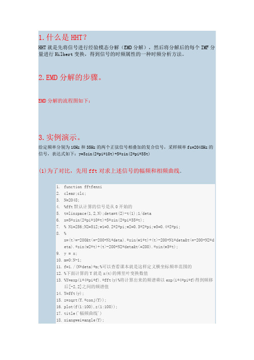
EMD分解的流程图如下
1.什么是HHT?HHT就是先将信号进行经验模态分解(EMD分解),然后将分解后的每个IMF分量进行Hilbert变换,得到信号的时频属性的一种时频分析方法。
2.EMD分解的步骤。
EMD分解的流程图如下:3.实例演示。
给定频率分别为10Hz和35Hz的两个正弦信号相叠加的复合信号,采样频率fs=2048Hz的信号,表达式如下:y=5sin(2*pi*10t)+5*sin(2*pi*35t)(1)为了对比,先用fft对求上述信号的幅频和相频曲线。
1.function fftfenxi2.clear;clc;3.N=2048;4.%fft默认计算的信号是从0开始的5.t=linspace(1,2,N);deta=t(2)-t(1);1/deta6.x=5*sin(2*pi*10*t)+5*sin(2*pi*35*t);7.% N1=256;N2=512;w1=0.2*2*pi;w2=0.3*2*pi;w3=0.4*2*pi;8.%x=(t>=-200&t<=-200+N1*deta).*sin(w1*t)+(t>-200+N1*deta&t<=-200+N2*deta).*sin(w2*t)+(t>-200+N2*deta&t<=200).*sin(w3*t);9.y = x;10.m=0:N-1;11.f=1./(N*deta)*m;%可以查看课本就是这样定义横坐标频率范围的12.%下面计算的Y就是x(t)的傅里叶变换数值13.%Y=exp(i*4*pi*f).*fft(y)%将计算出来的频谱乘以exp(i*4*pi*f)得到频移后[-2,2]之间的频谱值14.Y=fft(y);15.z=sqrt(Y.*conj(Y));16.plot(f(1:100),z(1:100));17.title('幅频曲线')18.xiangwei=angle(Y);19.figure(2)20.plot(f,xiangwei)21.title('相频曲线')22.figure(3)23.plot(t,y,'r')24.%axis([-2,2,0,1.2])25.title('原始信号')复制代码(2)用Hilbert变换直接求该信号的瞬时频率1.clear;clc;clf;2.%假设待分析的函数是z=t^33.N=2048;4.%fft默认计算的信号是从0开始的5.t=linspace(1,2,N);deta=t(2)-t(1);fs=1/deta;6.x=5*sin(2*pi*10*t)+5*sin(2*pi*35*t);7.z=x;8.hx=hilbert(z);9.xr=real(hx);xi=imag(hx);10.%计算瞬时振幅11.sz=sqrt(xr.^2+xi.^2);12.%计算瞬时相位13.sx=angle(hx);14.%计算瞬时频率15.dt=diff(t);16.dx=diff(sx);17.sp=dx./dt;18.plot(t(1:N-1),sp)19.title('瞬时频率')20.复制代码小结:傅里叶变换不能得到瞬时频率,即不能得到某个时刻的频率值。
dpo算法训练流程

DPO(Differentiable Policy Optimization)算法是一种深度强化学习训练方法,通过直接优化策略来提升智能体的表现。
以下是DPO算法的训练流程:
1. 定义环境:定义智能体所在的强化学习环境,包括状态、动作和奖励等要素。
2. 定义策略模型和参考模型,其中策略模型是需要训练的模型,参考模型是给定的预训练模型或人工构建的模型。
3. 对于给定的prompt,计算两个模型对正样本和负样本的概率。
正样本是人类选择的回复,负样本是被拒绝的回复。
4. 通过两个模型概率的差值构建DPO损失函数,惩罚策略模型对正样本概率的下降和负样本概率的上升。
5. 通过最小化DPO损失进行模型训练,不断迭代更新策略,使智能体在环境中获得更高的累积奖励。
6. 在训练过程中,使用DPO损失函数实现安全性约束的模型训练,不需要额外训练一个奖励模型。
7. 整个训练过程只需要策略模型和参考模型两个LLM模型,不需要额外的显存去加载奖励模型。
8. 训练完成后,保存微调后的模型。
以上是DPO算法的训练流程,具体实现细节可能会根据不同的应用场景和需求有所不同。
32主要的组合ATPG算法
2
2 故障D立方 • 在元件E的输出可产生故障信号D(D)的最小输入条
件称为故障D立方. • 其中D表示正常电路输出为1, 故障时输出为0, 记为 D=1/0; D则反之, 记为D=0/1;.
• 如果用表示正常电路的奇异立方, 用表示故障电路 的奇异立方, 则有
D = 1 n 0
D = 0 n 1
D-驱动(); 4. 相容性检查(); 5. 返回 ();
2004-5-25
北京大学微电子学研究院SOC研究所
9
D-驱赶( drive )
while (未试验D-边界上的故障响应) 选择下一个未试验的D-边 界门进行传播; while (未试验的故障响应扇出存在)
选择下一个未试验的故障响应扇出; 生成下一个未试验的传播D-立方; D-交叉选择的立方与测试立方; if (交叉失败或未定义) 继续; if (试验&失败所有传播D-立方) break; if (交叉成功) 增加传播 D-立方到测试立方-- recreate D-边界; 求所有分配的正向&反向蕴涵;
存储 D-边界, 算法规定, 测试立方, 扇出, 故障; break;
else if (交集失败 & 测试立方中的D and D) Backt rack (); else if (交集失败) break;
if (所有故障响应不能传播) Backt rack ();
2004-5-25
北京大学微电子学研究院SOC研究所
30
N
结束
失败
小结
• D-算法 – 第一个完备的ATPG算法
·它采用故障D-立方的概念来激活故障, 利用D驱赶的思
想逐级敏化从故障点到可几端的通路.
2004-5-25
moead算法流程步骤
moead算法流程步骤MOEA/D算法(多目标进化算法基于分解)可是个超有趣的算法呢!一、初始化种群。
这个算法一开始呀,要先创建一个初始种群哦。
就像是召集一群小伙伴来参加一场特别的游戏。
这个种群里的每个个体都像是一个独特的小选手,有着自己的特点。
这些个体的生成通常是随机的,就像在一个大盒子里随机抓取一些小物件一样,每个小物件都代表着一种可能的解。
二、分解多目标问题。
然后呢,它要把多目标问题分解成好多单目标子问题。
这就好比把一个超级复杂的大拼图,拆分成好多小块的拼图。
这样做的好处是,处理起来就没那么头疼啦。
每个子问题都可以单独去研究和解决,就像每个小拼图可以单独去找它该在的位置一样。
三、权重向量生成。
接下来要生成权重向量哦。
这个权重向量就像是每个小选手(个体)的比赛规则一样。
不同的权重向量会引导算法朝着不同的方向去寻找最优解。
它可以帮助算法在多个目标之间找到一个平衡,就像在游戏里,要平衡速度、力量和技巧这些不同的属性一样。
四、邻域关系确定。
再就是确定邻域关系啦。
这就像是在小伙伴们中间建立小团体一样。
每个个体都有自己的邻居,它们之间相互影响、相互交流。
在这个小团体里,大家可以分享信息,互相学习,这样就能让整个种群朝着更好的方向进化。
五、繁殖操作。
然后就到了繁殖操作啦。
这就像是小伙伴们之间互相合作,产生新的小伙伴。
通过交叉和变异这些操作,产生新的个体。
交叉就像是两个小伙伴交换一些特点,变异呢就像是某个小伙伴突然有了一个新的小创意。
六、更新种群。
最后就是更新种群啦。
根据前面那些操作得到的新个体,要看看哪些是比较优秀的,然后把它们留下来,替换掉原来种群里那些不那么好的个体。
就像在比赛中,表现好的选手留下来继续比赛,表现不好的就被淘汰啦。
这样不断地循环,种群就会越来越接近最优解,就像小伙伴们不断成长,变得越来越厉害一样。
P r e d i c t i o n 算 法 使 用

链路预测(Link prediction)中常用的评价指标(evaluation metrics)前提:链路预测只能预测边,不能预测节点。
只预测边!!!论文中提出两种链路预测的评价指标:AUC和精确度(Precision)1、 AUC:AUC指标的具体计算方法:首先我们知道衡量一个算法的好坏,需要把数据集划分为训练集和测试集,如何划分?比如可以删除10%的边(只删除边),那么这10%就是测试集,其余的90%的边和网络的全部节点就为训练集。
那么还有其它的边吗?我想绝大数现实的网络都不是完全图吧,所以肯定有两个节点之间没有连边的情况,那这部分边,我们称之为不存在的边。
一个算法(如CN)经过训练集训练得到网络中每一对节点之间的一个相似值(包括训练集中的边也会得到,测试集的边以及不存在的边显然也会得到)。
AUC指标就是比较测试集中的边的相似值? 与? 不存在的边的相似性的大小。
如果测试集中边的相似值大于不存在边的相似值,就说明效果好啊,+ 1呗;如果测试集中边的相似值等于不存在边的相似值,就说明跟随机选择差不多啊,那就+ 0.5呗,没啥意义,还不如不用算法;如果测试集中边的相似值小于不存在边的相似值,就说明你这算法也太差了吧,随机的都比不过,反其道行之啊兄弟,+ 0吧;那么分母就是测试集中的边与不存在中的边的比较次数,比如测试集中2条边,不存在中3条边,那么比较次数就是6次啦。
2、精确度(Precision)注意:这里提到的精确度和你之前听到的二分类问题的precision、accuracy、recall、F1都毫无关系!!!那么这种精确度怎样计算呢?算法(如CN)不是得到每一个节点对之间的相似值了嘛,这时候去掉训练集中的边,还剩什么了?就剩测试集中的边和不存在的边以及边对应的相似值,按相似值的大小倒序排列这些边。
排序后取前L个(比如给它赋值50,即L=50),看一看这里有几个是测试集中的啊,比如有20个,那么精确度就等于20-50。
dmd方法与pod方法

dmd方法与pod方法DMD方法与POD方法,解析两种数据分析技术。
数据分析在当今社会中扮演着越来越重要的角色,而DMD (Dynamic Mode Decomposition,动态模态分解)和POD(Proper Orthogonal Decomposition,正交分解)方法是两种常用的数据分析技术。
它们可以帮助我们理解复杂的系统行为,从而为决策制定和问题解决提供支持。
本文将介绍这两种方法的基本原理和应用领域。
首先,让我们来了解一下DMD方法。
DMD是一种用于分析动态系统的技术,它可以从时间序列数据中提取动态模态,并用这些模态来描述系统的演化过程。
DMD方法可以应用于多个领域,如流体力学、气象学、生物医学工程等。
通过对系统的动态行为进行分解和分析,DMD方法可以帮助我们理解系统的振荡模式、频率和增长率,从而为系统的预测和控制提供支持。
另一方面,POD方法是一种用于分析空间系统的技术,它可以从空间分布的数据中提取出最重要的模态,并用这些模态来描述系统的变化。
POD方法在流体力学、结构动力学、地质勘探等领域有着广泛的应用。
通过对系统的空间分布进行分解和分析,POD方法可以帮助我们理解系统的主要特征、模态的空间分布以及它们之间的相互作用,从而为系统的优化和设计提供支持。
虽然DMD方法和POD方法在原理和应用领域上有所不同,但它们都是基于对数据进行分解和模态提取的思想。
在实际应用中,可以根据具体问题的特点和数据的性质选择合适的方法进行分析。
此外,还可以将DMD方法和POD方法结合起来,以获取更加全面和深入的系统信息。
总之,DMD方法和POD方法都是重要的数据分析技术,它们为我们理解复杂系统提供了有力的工具和方法。
通过对这两种方法的深入了解和灵活运用,我们可以更好地把握系统的特征和行为,为科学研究和工程实践提供支持。
MIMO通信系统中的检测算法
MIMO通信系统中的检测算法在MIMO(Multiple-Input Multiple-Output)通信系统中,检测算法是非常重要的,它可以帮助接收端准确地恢复发送端发送的数据。
MIMO系统通过在发送端和接收端同时使用多个天线,可以显著提高系统的容量和可靠性。
然而,由于多天线导致的信号间干扰,MIMO系统的检测变得更加复杂。
本文将介绍一些常见的MIMO检测算法。
2. 最小均方误差(Minimum Mean Square Error,MMSE)检测算法:MMSE算法是一种基于线性检测算法的改进算法。
它通过最小化接收信号与已知发射信号之间的均方误差来进行检测。
MMSE算法可以有效地减小干扰信号,并提高系统的误码率性能。
3. 梯度投影算法(Gradient Projection,GP):GP算法是一种基于优化的检测算法。
它通过将MIMO通信系统中的检测问题转化为约束优化问题来进行检测。
GP算法通过不断迭代优化接收信号估计来最小化损失函数,并在每次迭代中进行梯度投影来满足约束条件。
该算法可以在复杂的MIMO系统中实现近似最优的检测性能。
4. 近似消息传递算法(Approximate Message Passing,AMP):AMP算法是一种基于概率图模型的检测算法。
它通过树型图和因子图的推断方法来进行检测。
AMP算法在分布估计和误码率性能方面表现出色,尤其适用于大规模MIMO系统。
5. 近似最小误码率(Approximate Minimum Bit Error Rate,AMBER)算法:AMBER算法是一种适用于多用户MIMO系统的近似检测算法。
它通过近似计算最小误码率而不是最小误码率信噪比来进行检测。
AMBER算法可以有效地减小计算复杂度,并且在高信噪比下性能接近于最优检测算法。
总结起来,MIMO通信系统中的检测算法有线性检测算法、MMSE算法、GP算法、AMP算法和AMBER算法等。
这些算法在不同的场景和要求下具有不同的优势和性能。
em算法原理
EM算法原理一、简介EM(Expectation Maximization)算法是一种常见的统计学习方法,用于估计参数和解决一些难以处理的问题,特别是在存在隐变量的情况下。
EM算法最初由数学家罗伯特·卢德米勒(RobertLushmiller)和理查德·贝尔曼(RichardBellman)在20世纪50年代提出,后来由 statisticiansDempster, Laird, and Rubin 进一步发展,因此也被命名为Dempster-Laird-Rubin算法。
EM算法在许多领域都有广泛的应用,如混合高斯模型、隐马尔可夫模型、高斯过程回归等。
二、EM算法的步骤EM算法主要由两个步骤组成:E步(ExpectationStep)和M步(Maximization Step),这两个步骤在迭代过程中交替进行。
1.E步:计算隐变量的条件期望。
给定当前的参数估计值,计算隐变量的条件期望,通常表示为参数的函数。
这个步骤中,隐变量对数似然函数的参数更新起着关键作用。
2.M步:最大化期望值函数。
在E步计算出期望值之后,M步将尝试找到一组参数,使得这个期望值函数最大。
这个步骤中,通常使用优化算法来找到使期望值函数最大的参数值。
这两个步骤在迭代过程中交替进行,每次迭代都更新了参数的估计值,直到满足某个停止准则(如参数收敛或达到预设的最大迭代次数)。
三、EM算法的特点与优点1.处理隐变量:EM算法能够处理数据中存在的隐变量问题,这是它与其他参数估计方法相比的一大优势。
通过估计隐变量的概率分布,EM算法能够更准确地描述数据的生成过程。
2.简单易行:相对于其他优化算法,EM算法相对简单易懂,也容易实现。
它的主要目标是最优化一个简单的对数似然函数,这使得EM算法在许多情况下都能给出很好的结果。
3.稳健性:对于一些数据异常或丢失的情况,EM算法往往表现出较好的稳健性。
这是因为EM算法在估计参数时,会考虑到所有可用的数据,而不仅仅是正常的数据点。
POD算法介绍

例: nAreaHeight
= 9 // 求平均亮度时选取的 Block的 Height
nAreaWidth
= 9 // 求平均亮度时选取的 Block的 Width
代表取9×9的 block ,计算亮度平均值,Gr_ave =( Gr_P1+ Gr_P2+…+ Gr_P81)/ 81
DeadUnit = 1
的亮度值与该block的亮度平均值的百分比差,超过woundSpc则测试
NG。
例:nAreaHeight
nAreaWidth
= 9 // 求平均亮度时选取的 Block的 Height = 9 // 求平均亮度时选取的 Block的 Width
代表取9×9的 block ,计算亮度平均值,Gr_ave =( Gr_P1+ Gr_P2+…+ Gr_P81)/ 81 若:(abs(Gr_P41- Gr_ave )/ Gr_ave )> = woundSpc --------------测试NG 若: (abs(Gr_P41- Gr_ave )/ Gr_ave )<woundSpc --------------测试PASS
Wound_EN = 1
// 1:测试wound ;0:不测试wound
Dead_EN = 1
// 1:测试Dead; 0:不测试Dead
说明:紫色标注的部分为设定档中需要设定的规格部分。
下图为不良品图片示例:
-2-
Wound不良
-3-
Dead不良
-4-
Wound算法介绍
1.将得到的Raw8图分成R、Gr、Gb、B 四个channel(详见下页图示)
(abs(Gr_P41-Gr_ave )/ Gr_ave )> Deadpc --------------测试附近的pixel是否也超规格,检测到有
BP算法程序实现
BP算法程序实现BP算法(Back Propagation Algorithm,即反向传播算法)是一种用于训练神经网络的常用算法。
它的基本思想是通过不断地调整神经元之间的连接权值,使得网络的输出接近于期望的输出。
在实现BP算法时,需要进行以下几个步骤:1.初始化参数:首先,需要初始化神经网络的权值和偏置,通常可以使用随机的小数来初始化。
同时,需要设置好网络的学习率和最大迭代次数。
2.前向传播:通过前向传播过程,将输入数据输入到神经网络中,并计算出每个神经元的输出。
具体来说,对于第一层的神经元,它们的输出即为输入数据。
对于后续的层,可以使用如下公式计算输出:a[i] = sigmoid(z[i])其中,a[i]表示第i层的输出,z[i]为第i层的输入加权和,sigmoid为激活函数。
3.计算误差:根据网络的输出和期望的输出,可以计算出网络的误差。
一般来说,可以使用均方差作为误差的度量指标。
loss = 1/(2 * n) * Σ(y - a)^2其中,n为训练样本的数量,y为期望输出,a为网络的实际输出。
4.反向传播:通过反向传播算法,将误差从输出层向输入层逐层传播,更新权值和偏置。
具体来说,需要计算每一层神经元的误差,并使用如下公式更新权值和偏置:delta[i] = delta[i+1] * W[i+1]' * sigmoid_derivative(z[i])W[i] = W[i] + learning_rate * delta[i] * a[i-1]'b[i] = b[i] + learning_rate * delta[i]其中,delta[i]为第i层的误差,W[i]为第i层与i+1层之间的权值,b[i]为第i层的偏置,learning_rate为学习率,sigmoid_derivative为sigmoid函数的导数。
5.迭代更新:根据步骤4中的更新公式,不断迭代调整权值和偏置,直到达到最大迭代次数或误差小于一些阈值。
P r e d i c t i o n 算 法 使 用
YOLO v2算法详解论文: YOLO9000:Better,Faster,Stronger接下来基本上按照文章的顺序来解读一下算法,这样读起来也比较清晰。
主要包括三个部分:Better,Faster,Stronger,其中前面两部分基本上讲的是YOLO v2,最后一部分讲的是YOLO9000。
这部分细节很多,想要详细了解的话建议还是看源码。
1、Batch Normalization2、High Resolution Classifier首先fine-tuning的作用不言而喻,现在基本跑个classification或detection的模型都不会从随机初始化所有参数开始,所以一般都是用预训练的网络来finetuning自己的网络,而且预训练的网络基本上都是在ImageNet数据集上跑的,一方面数据量大,另一方面训练时间久,而且这样的网络都可以在相应的github上找到。
3、Convolutional With Anchor Boxes原来的YOLO是利用全连接层直接预测bounding box的坐标,而YOLOv2借鉴了Faster R-CNN的思想,引入anchor。
首先将原网络的全连接层和最后一个pooling层去掉,使得最后的卷积层可以有更高分辨率的特征;然后缩减网络,用416*416大小的输入代替原来448*448。
这样做的原因在于希望得到的特征图都有奇数大小的宽和高,奇数大小的宽和高会使得每个特征图在划分cell的时候就只有一个center cell(比如可以划分成7*7或9*9个cell,center cell只有一个,如果划分成8*8或10*10的,center cell就有4个)。
为什么希望只有一个center cell呢?因为大的object一般会占据图像的中心,所以希望用一个center cell去预测,而不是4个center cell去预测。
网络最终将416*416的输入变成13*13大小的feature map输出,也就是缩小比例为32。
基于POMDP强化学习的动态频谱分配算法

2009年12月第32卷第6期北京邮电大学学报Journal of Beijing University of Posts and TelecommunicationsDec.2009Vol.32No.6文章编号:100725321(2009)0620125205基于POMDP 强化学习的动态频谱分配算法唐 伦1,2, 陈前斌2, 曾孝平1(11重庆大学通信工程学院,重庆400044;21重庆邮电大学通信与信息工程学院,重庆400065)摘要:提出基于VCG 机制的动态频谱分配博弈模型,解决了认知无线网络环境存在的信息约束限制、分布式特性和频谱分配动态、复杂性问题;提出一种基于动态频谱分配的部分可观察马尔可夫决策过程(POMDP )强化学习算法.认知用户通过对历史信息的观察、统计,为提高竞拍策略的奖赏值而进行不断的学习获取最优竞拍策略.将POMDP 强化学习转变为信度状态马尔可夫决策过程(belief MDP )最优策略学习.采用值迭代算法求解信度状态MDP 模型的解.仿真结果表明,基于POMDP 强化学习算法可显著改善认知用户的行为,提高动态频谱分配性能.关 键 词:动态频谱分配;VCG 机制;认知网络中图分类号:TN929153 文献标志码:AA Novel Dynamic Spectrum Allocation AlgorithmB ased onPOMDP R einforcement LearningTAN G Lun 1,2, CHEN Qian 2bin 2, ZEN G Xiao 2ping 1(11College of Communication Engineering ,Chongqing University ,Chongqing 400044,China ;21School of Communication and Information Engineering ,Chongqing University of Posts and Telecommunications ,Chongqing 400065,China )Abstract :A game model based on Vickrey 2Clarke 2Groves (VCG )mechanism for dynamic spectrum al 2location is presented ,to solve the complexity problem of the dynamic spectrum allocation and reduce information exchange during the dynamic spectrum allocation.Further ,a partially observable Markov decision processes (POMDP )reinforcement learning algorithm is presented.Through the observation and statistics of historical information ,the secondary users enhance the reward value of bidding strate 2gy by continuous learning ,so as to obtain the optimal bidding strategy.Finally ,the POMDP rein 2forcement learning algorithm is transformed into optimal strategy learning algorithm of belief Markovdecision processes (MDP ),which is solved by using the value iteration algorithm.The simulation re 2sults reveales that the POMDP reinforcement learning algorithm can significantly improve the perfor 2mance of dynamic spectrum allocation.K ey w ords :dynamic spectrum allocation ;Vickrey 2Clarke 2Groves mechanism ;cognitive network收稿日期:2008210213基金项目:国家科技重大专项项目(2008ZX030032005);新世纪优秀人才支持计划项目(NCET 20620778);重庆市教育委员会科学技术研究项目(K J090501)作者简介:唐 伦(1973—),男,博士生,E 2mail :tangl @ ;陈前斌(1967—),男,教授,博士生导师;曾孝平(1956—),男,教授,博士生导师. 目前的无线通信系统采用固定频谱分配,存在频谱利用率低及频谱资源匮乏等问题[1].针对动态频谱分配的研究主要包括:1)频谱分配方法问题[224];2)提高动态频谱分配方法性能问题[5].近年来,博弈论成为研究动态频谱分配的主要方法,文献[4]对CR 网络提出基于博弈论的自适应信道分配方案;文献[5]将动态频谱分配问题建模为一个垄断市场竞争问题;文献[6]从博弈论角度对动态频谱分配中的认知无线网络用户行为、动态分布式设计和优化分析等方面进行了综述.本文从机制设计角度提出一种基于VCG机制动态频谱分配博弈模型.为进一步提高认知无线网络中频谱分配方法的性能,提出一种动态频谱分配的POMDP强化学习算法.1 频谱动态分配方案111 系统描述假设一段频谱有N条信道,每个信道被标记为j∈{1,2,…,N},N个无线信道最初被授权给主用户(PU,primary users),主用户专有地接入信道.在每个时隙,假设每条信道有on或off状态:on代表该信道当前正在被PU使用;off代表该信道未被PU使用,允许非授权用户,即认知用户(SU,sec2 ondary users)基于协商或机会的方式动态接入主用户的授权频段[7].N条信道的空闲情况用机会频谱映射图(spectrum opportunity map)来刻画[8].假设M(M>N)个认知用户竞争这N条信道的频谱机会,每个SU索引为i∈{1,2,…,M},信道分配矩阵记为Z t=[z t ij]M×Nz t ij=1,信道j被分配给SU i 0,其他无SU i时的信道分配矩阵可以表示为Z t-i= [z t kj](M-1)×N.112 频谱分配的非合作博弈模型为实现高效动态频谱分配,需要克服动态频谱环境中存在的困难,包括频谱环境的动态特性、多用户频谱分配问题中信息约束限制和分布式特性,还需考虑认知用户的行为[6].认知用户相互作用策略可影响动态频谱分配,同时,相互竞争的SU是自私、有策略的.因此,它们拥有的信息是私有的,不与他人共享的,即非合作的.博弈论[9]是研究不同主体在策略相互依存(strategic interdependence)情形下相互作用的科学[9],可很好地解决动态频谱分配的问题.首先,利用博弈论对认知用户的动态频谱共享进行建模,在形式化的博弈结构中分析认知用户的行为和作用;其次,博弈论在频谱分配问题上有多种优化准则,如对频谱利用率的优化可以建模为一个多目标优化问题;第三,非合作博弈论能仅利用局部或私有的信息实现有效的分布式动态频谱分配方法.将动态频谱分配建模为认知用户间的非合作博弈问题,动态频谱分配非合作博弈模型包括3部分:1)局中人(player),即认知用户.动态频谱分配过程中,认知用户相互作用,基于协商或机会的方式动态接入主用户的授权频段.假设认知用户是理性、自私和策略性用户,以最大化自身的利益为目标,其中每个认知用户的私有信息是不向其他用户公开的.2)策略(strategy).竞拍策略向量b t i=[b t i1,…,b t iN],其中,b t iN为t时刻对信道N的报价.认知用户通过竞拍方式获取频谱资源,根据可用频谱率信息、业务和信道特性对其他认知用户的竞拍行为的影响选择各自的竞拍策略.3)效用/收益(profit).认知用户i的效用函数[10]为R(i)=∑Nj=1ztijb t ij.基于VCG机制的动态频谱分配博弈模型如图1所示.图1 基于VCG机制的动态频谱分配博弈模型假设在网络中配置轮询的媒体接入协议[11],由中央频谱分配仲裁者(CSM,central spectrum mod2 erator)进行裁决,CSM为动态分配资源部署VCG 机制[12],并应用于网络资源分配[13].CSM根据PU 的行为重复地对空闲的频谱进行拍卖,将无线频谱分配建模为频谱资源拍卖模型.基于VCG机制的频谱分配非合作博弈分为5个步骤.步骤1 CSM通过广播频谱资源可用性状态宣布拍卖.步骤2 SU接收到公告后根据广播的信息和621北京邮电大学学报 第32卷SU 的需求、经验、历史信息计算其竞拍策略向量b ti =[b ti 1,…,b tiN ]∈R N.步骤3 每个SU 递交它们的竞拍向量之后,CSM 根据计算支付规则和分配规则进行信道分配和支付(payment )计算2种形式的计算.CSM 根据递交的竞拍向量为每个SU 计算信道分配向量z t i =[z t i 1,…,z t iN ]∈{0,1}N .为迫使各SU 真实地申报其竞拍方案,CSM 还将计算SU 在当前博弈阶段使用资源应付出的代价τti .步骤4 竞拍的结果被传送到SU ,继而可以配置其在不同层的传输策略,并通过分配的频谱资源传输数据.步骤5 在下一个时隙t +1,下一个拍卖活动开始,重复步骤1~4.113 基于VCG 机制的频谱分配算法CSM 根据公平原则分配信道,使总的社会福利最大化[9]:Zt ,opt=arg max∑Mi =1∑Nj =1z t ij b t ij(1)VCG 机制根据以上最优信道分配原则Zt ,opt=[z t ,optij ]M ×N 决定SU i 所应交付的税款[9]为τt i =∑Mk =1,k ≠i ∑Nj =1zt ,opt ijb tkj -max Zt -i∈Z t-i ∑Mk =1,k ≠i ∑Nj =1zt kj b tkj(2)式(1)和式(2)所描述的优化问题可应用线性规划或启发式算法有效地解决[14].基于VCG 机制的频谱分配主要有2个优点:1)τt i 的确定保证了认知用户正确竞拍策略(报价)b t i =[b t i 1,…,b t iN],以使自己效用最优,∑Mi =1∑Nj =1z t ij b t ij到达最大[9];2)保证用户的策略不受其他用户的策略影响,VCG 机制是激励相容的直接机制[9],它暗示在任何情况下任何竞价人都不能从谎报中获益,偏离真实报价不能使得自身的收益最大,即说真话策略是最优策略[13].2 基于VCG 机制的动态频谱分配POMDP 强化学习算法 为提高频谱分配方法的性能,SU 可通过对自身历史信息的观察、统计和学习,有策略地预测当前动作对后续行动的影响,得到最佳竞拍策略,优化动态频谱分配性能.为此,提出基于VCG 机制的动态频谱分配POMDP 强化学习算法.211 最优竞拍策略问题在每个时隙的开始,SU 提交它们的竞拍向量b t i ,CSM 返回信道分配情况z t i 和τt i .一般情况下,为了减小系统信令开销等信息,SU i 不能观测和监听到其他SU 的竞拍方案、信道状态和报酬,SU 为提高其在认知无线网络中动态频谱分配性能,需要在众多不确定环境状态下通过学习来优化拍卖过程的竞拍策略.SU 根据观察拍卖竞拍结果中的部分或全部历史信息,估计其对未来奖赏值的影响,通过POMDP 强化学习从而选择他们的最佳竞拍方案.212 频谱拍卖机制中POMDP 强化学习算法频谱拍卖机制中的POMDP 强化学习由六元组〈S ,A ,P ,R ,Z ,O 〉定义.1)环境状态集S ,包括N 条信道的可用性情况,信道分配情况.2)系统行为集合A .SU i 的竞拍策略向量A =b ti =[b ti 1,…,b tiN ]∈R N构成系统行动集合.3)记P (s t +1,a ,s t )为系统在状态s t 采用a 动作使环境状态转移到s t +1的概率,转移函数P (s t +1,a ,s t )=Pr (S t +1=s t +1|S t =s t ,A t =a )4)Z 为观察的集合,即SU 全部或部分可观察的历史信息的集合,包括历史状态信息s t i 、竞拍策略b ti 、信道分配情况z ti 和τt i ,o t i ={s 0i ,b 0i ,z 0i ,τ0i ,…,s t -1i ,b t -1i ,z t -1i ,τt -1i ,s ti }5)用户观察函数O ∶S ×A →Π(Z ),指示了被观察信道的可用性,在观察分析历史信息的基础上,用户选择1组信道接入.系统在采取动作a 转移到状态s 时,观察函数O 确定其在可能观察上的概率分布.记观察函数为o (a ,s ,z )=Pr (Z t +1=z |A t =a ,S t +1=s )6)奖赏函数R ∶S ×A →R 和状态转移函数T :S ×A →Π(S ).记R (s t +1,a ,s t )为系统在状态s t 采用a 动作使环境状态转移到s t +1获得的瞬时奖赏值.寻找POMDP 问题的最优策略,需要把过程的全部历史记住,即策略为整个历史到行为空间的映射:π∶H →A ,而记住整个历史信息是不可能的,可通过引入信息状态或信度状态对过去历史信息的统计描述,保存寻找最优策略的所有信息.可以证明,原POMDP 问题最优策略学习转变为信度状态MDP (belief MDP )最优策略学习[15].信度状态b 是在状态空间的一个概率分布721第6期 唐 伦等:基于POMDP 强化学习的动态频谱分配算法Π(S ),信度状态b 的某个分量b (s t )表示处于状态s t的概率值.它不仅包含了历史信息,还可以根据Bayes 原理利用最近的“动作-状态”对进行更新.给定1个信度状态b (s t ),在执行行为a ,得到观测状态z 后,新的信度状态的第s t +1个分量为b az (st +1)=o (a ,s ,z )∑s t∈SP (s t +1,a ,s t )b (s t)∑st +1∈S∑s t∈So (a ,s ,z )P (s t +1,a ,s t )b (s t)(3)在给定信度状态b 和行为a 的前提下,得到观测状态z 的概率为σ(b ,a ,z )=Pr (z |b ,a )=∑st +1∈S ∑s t∈So (a ,s ,z )P (s t+1,a ,st)b (s t)(4)则式(3)简化为b az (s )=o (a ,s ,z )∑s ′∈Sp (s ′,a ,s )b (s ′)σ(b ,a ,z )(5)认知用户通过提高其竞拍策略的奖赏值,不断地学习以获取最优竞拍策略,即从信度状态到动作的1个映射,使期望折扣回报(奖赏)最大,从信度状态b 开始,策略π的期望折扣回报定义为V π(b )=E∑∞t =0γtR (st,a t )|b ,π(6)其中γ为折扣因子.竞拍策略的优劣可用值函数来衡量.给定2个策略π1和π2,若对于任意的b ,有Vπ1(b )≥Vπ2(b ),则称策略π1优于策略π2.若1个策略优于其他所有策略,则称其为最优策略,用π3表示.相应的最优值函数则为V 3.通过这样的转化,POMDP 问题最优策略学习转变为信度状态MDP 最优策略学习,但此时状态空间已不是原来的状态空间,而是信度状态空间,需要重新定义奖赏函数w (b ,a )=∑s ∈Sba z (s )R (s ,a )(7)由信度状态组成的MDP ,其值函数定义为V 3n (b )=maxa ∈A∑sw (b ,a )+γ∑oσ(b ,a ,z )V 3n -1(b az )(8)故求解POMDP 就转化为求解MDP .已经证明MDP 可以通过随机动态规划来进行求解.213 值迭代算法值迭代是求解信度状态MDP 模型的标准方法之一,计算近似最优值的算法如下.Value Iteration (V ,ε): ∥初始化值函数,并计算精度η n ←0,V 0←V ,η←ε(1-γ)/2γ ∥循环,迭代值函数,并检测是否达到终止条件 Repeat {V 3n(b )←maxa ∈A∑sw (b ,a )+γ∑oσ(b ,a ,z )×V3n -1(b a z ) n ←n +1}until (max b ∈B|V n (b )-V n -1(b )|≤η) ∥测试迭代终止条件,如果Bellman 误差(max b ∈B|V n (b )-V n -1(b )|≤η)足够小,迭代过程终止,并输出结果Return V n3 仿真结果在仿真中,为了证明所提出的学习算法可以预测当前行为,即确定最佳竞拍策略对未来奖赏值的影响,应根据获得的效用来改善用户的行为,包括2种方案:1)认知用户没有应用学习算法;2)认知用户使用POMDP 强化学习算法来确定其最佳竞拍策略.图2所示为2种方案下的累计折扣奖赏.每个时隙所获得的平均奖赏值分别为0151和0172时.POMDP 强化学习算法使平均奖赏值提高了大约41%,这表明POMDP 学习算法能有效地预测未来的奖赏值,使认知用户提出更加准确的竞拍策略.图2 认知用户累计折扣奖赏4 结束语笔者考虑了认知用户可能影响频谱分配的自私网络行为、频谱分配中的信息约束限制和分布式特性,将无线认知网络频谱分配问题建模为一种通用的动态频谱分配博弈模型,通过VCG 机制的部署821北京邮电大学学报 第32卷和实施,能有效地进行动态频谱分配,防止自私用户可能存在的欺骗行为.为进一步提高认知无线网络中频谱分配方法的性能,提出一种动态频谱分配的POMDP强化学习算法,讨论了SU依据其自身历史信息的观察统计,通过经验和学习,有策略地预测当前动作对后续行动的影响,做出最佳竞拍方案.仿真结果表明,基于POMDP强化学习算法可显著地改善认知用户的行为,提高动态频谱分配的性能.参考文献:[1] Mitola J,Maguire G.Cognitive radio:making softwareradios more personal[J].IEEE Personal Commun, 1999,6(4):13218.[2] 曾志民,刘琦,冯春燕,等.认知无线电网络自适应带宽分配机制及性能分析[J].北京邮电大学学报,2009,32(1):42.Zeng Zhimin,Liu Qi,Feng Chunyan,et al.An adaptivebandwidth allocation mechanism and performance analysis in cognitive radio networks[J].Journal of Beijing Uni2 versity of Posts and Telecommunications,2009,32(1):42.[3] 邱晶,周正.认知无线电网络中的分布式动态频谱共享[J].北京邮电大学学报,2009,32(1):72.Qiu Jing,Zhou Zheng.Dynamic spectrum sharing strate2 gy in cognitive radio systems[J].Journal of Beijing Uni2 versity of Posts and Telecommunications,2009,32(1):72.[4] Nie N,Comaniciu C.Adaptive channel allocation spec2trum etiquette for cognitive radio networks[C]∥Proceed2 ings of IEEE DySPAN’05.Baltimore:[s.n.],2005:2692278.[5] Niyato D,Hossain petitive spectrum sharing incognitive radio networks:a dynamic game approach[J].IEEE Transactions on Wireless Communications,2008, 7(7):265122660.[6] Zhu Ji,Liu K J R.Dynamic spectrum sharing:a gametheoretical overview[J].Communications Magazine, 2007,45(5):88294.[7] Chou C T,Shankar N S,K im H,et al.What and howmuch to gain by spectrum agility?[J].IEEE Journal Sel Areas Commun,2007,25(3):5762588.[8] Wang Beibei,Zhu Ji.Self2learning repeated game frame2work for distributed primary2prioritized dynamic spectrum access[C]∥Proceedings of IEEE SECON2007.San Diego:[s.n.],2007:6312638.[9] Nisan N.Algorithmic game theory[M].Cambridge:Cambridge University Press,2007.[10] Cao L,Zheng H.Spectrum allocation in Ad hoc net2works via local bargaining[C]∥IEEE SECON.SantaClara:[s.n.],2005:4752486.[11] IEEE802.11e/D5.0—2003,Wireless medium accesscontrol(MAC)and physical layer(PHY)specifica2tions:medium access control(MAC)enhancements forquality of service(QoS)[S].2003.[12] K lemperer P.Auction theory:a guide to the literature[J].Journal Economics Surveys,1999,13(3):2272286.[13] K loeck C,Jaekel H,Jondral F.Auction sequence as anew resource allocation mechanism[C]∥Proceedings ofV TC’05.Dallas:[s.n.],2005:2402244.[14] Boyd S P,Vandenberghe L.Convex optimization[M].Cambridge:Cambridge University Press,2004. [15] K aelbling L P,Littman M L,Cassandra A R.Planningand acting in partially observable stochastic domains[J].Artificial Intelligence,1998,10(1):992134.921第6期 唐 伦等:基于POMDP强化学习的动态频谱分配算法。
ATPG自动测试生成模式

2)FAN 算法在搜索过程中采用更多的启发性信息和电路结构信息, 主要从减少回溯次数和缩短两 次回溯之间的处理时间这两方面入手; FAN 算法加速测试生成。
“测试”与“验证”的区别: 验证(Verification)的目的是检查设计中的错误,确保设计符合其设计规范和所期望的功能; 测试(Testing)则是检查芯片的加工制造过程中所产生的缺陷和故障。
DFT
ATPG概述 ATPG算法 SAT &ATPG
芯片测试主要环节:
I. 故障建模;对电路中可能存在的故障进行建模分析; II. III. 测试向量生成; 利用各种集成有 ATPG 算法的工具生成测试向量;
DFT
ATPG概述 ATPG算法 SAT &ATPG
• 故障敏化: • 将所有节点赋值为 X;对目标
故障进行赋值,故障点值为 0 即 s-a-0,则赋值为 D;故障 点值为 1 即s-a-1,则赋值为
D;通过J- frontier向前/后 蕴含对未分配的点赋值,确认 有无冲突产生,直至为所有的 输入找到一组无冲突赋值;
测试向量(集): 测试向量使得故障电路模块和正确电路模块的输出不同;
测试向量生成需要 EDA厂家的 ATPG 工具, 用工具来选择建立哪种故障模型, 然后 ATPG 工具将 分别根据各种故障模型生成相应的测试向量。
ATPG算法评估标准: 一个好的工业级ATPG算法应能够在更短的时间内,产生更少的测试向量数, 并获得更高的测试覆盖率,使得测试成本更低。
DFT
ATPG概述 ATPG算法 SAT &ATPG
moead算法的具体流程

moead算法的具体流程下载温馨提示:该文档是我店铺精心编制而成,希望大家下载以后,能够帮助大家解决实际的问题。
文档下载后可定制随意修改,请根据实际需要进行相应的调整和使用,谢谢!并且,本店铺为大家提供各种各样类型的实用资料,如教育随笔、日记赏析、句子摘抄、古诗大全、经典美文、话题作文、工作总结、词语解析、文案摘录、其他资料等等,如想了解不同资料格式和写法,敬请关注!Download tips: This document is carefully compiled by theeditor. I hope that after you download them,they can help yousolve practical problems. The document can be customized andmodified after downloading,please adjust and use it according toactual needs, thank you!In addition, our shop provides you with various types ofpractical materials,such as educational essays, diaryappreciation,sentence excerpts,ancient poems,classic articles,topic composition,work summary,word parsing,copy excerpts,other materials and so on,want to know different data formats andwriting methods,please pay attention!1. 初始化确定优化问题的目标函数和决策变量。
设置算法的参数,如种群大小、邻域大小、迭代次数等。
PIPEMD算法

PIPEMD算法
整个MD5(信息摘要算法5)的基本过程可以概括为以下几个步骤:填充:消息为$K$bits的原始消息数据尾部填充长度为$P$bits
的标识$1000…0\,1\le P\le 512$(至少要填充一个bit)。
使得填充后的消息位数满足$K+P\equiv 448(mod\,512)$(注:当$K\equiv
448(mod\,512)$)时,$P=512$。
填充好的消息尾部需要在附加$K$值的低64位即
$K\,mod\,2^{64}$。
最终结果得到$K+P+64\equiv 0(mod\,512)$的填充消息。
分块:把填充之后的消息结果分割为$L$个$512-bit$分组:
$Y_0..Y_{L-1}$。
也是$L$个64字节的分组。
缓冲区初始化:初始化一个$128-bit$的MD缓冲区,记为$CV_q$,表示成4个$32-bit(4个byte)$的寄存器$(A,B,C,D)$;$CV_0=IV(IV 为16进制初值)$。
循环压缩:对L个消息分组$Y_q(q=0,1,…L-1)$,逐个经过4重循环的压缩算法。
表示为:
CV0=IV
CV0=IV
CVi=HMD5(CVi−1,Yi)
CVi=HMD5(CVi−1,Yi)
得出结果:最后一个消息分组经过$H_{MD5}$压缩得到MD5结果
为MD值,即$MD=CV_L$。
POD算法介绍范文
POD算法介绍范文在介绍POD算法之前,我们首先要了解一些基础概念。
1.空间特征向量:空间特征向量是指在一些数据集中最能代表整体特征的向量。
具体来说,对于一个包含N个数据样本的数据集,空间特征向量是一个N维向量,它能够代表数据集中样本间的主要相似性和差异性。
2.空间特征值:空间特征值是指与空间特征向量相对应的特征值。
它表示了每个特征向量在整个数据集中的重要性程度。
1.数据预处理:首先,需要对原始数据进行预处理,包括数据归一化、去除噪声等处理操作,以提高POD算法的稳定性和准确性。
2.构建数据矩阵:将预处理后的数据组成数据矩阵X,其中每一列代表一个数据样本,每一行代表一个特征。
3.计算数据的协方差矩阵:通过计算数据矩阵X的协方差矩阵C,可以得到数据的相似性和差异性。
4.对协方差矩阵进行特征值分解:将协方差矩阵C分解为特征值矩阵Λ和特征向量矩阵Φ,其中Λ为一个对角矩阵,对角线上的元素为特征值,Φ的每一列为对应的特征向量。
5.选择主要特征向量:根据特征值的大小,选择最能代表原始数据的前k个特征向量,其中k为降维后的维数。
一般情况下,选取特征值大于一些阈值的特征向量作为主要特征向量。
6.数据重建:将选取的主要特征向量与原始数据进行线性组合,即可得到重建后的数据。
重建后的数据能够尽可能地保留原始数据的主要特征。
POD算法的优点是能够在保留原始数据主要特征的同时,实现数据的降维。
它适用于处理高维数据,解决传统降维方法在处理高维数据时计算量大、效果差的问题。
此外,POD算法还能够提取数据的隐含信息,并能够应用于数据分析、异常检测、图像处理等领域。
然而,POD算法也存在一些不足之处。
首先,POD算法在处理非线性数据时效果可能较差,因为它假设数据具有线性相关性。
此外,POD算法对数据的初始处理比较敏感,对噪声和异常值的处理不够灵活。
最后,POD算法需要用到协方差矩阵,计算复杂度较高。
总结来说,POD算法是一种常用的数据降维方法,通过对数据进行正交分解,提取主要的空间特征,从而实现数据的降维。
- 1、下载文档前请自行甄别文档内容的完整性,平台不提供额外的编辑、内容补充、找答案等附加服务。
- 2、"仅部分预览"的文档,不可在线预览部分如存在完整性等问题,可反馈申请退款(可完整预览的文档不适用该条件!)。
- 3、如文档侵犯您的权益,请联系客服反馈,我们会尽快为您处理(人工客服工作时间:9:00-18:30)。
ALGORITHMS FOR
PATTERN GENERATION
TOM KIRKLAND Microelectronics and Computer Technology Corp. M. RAY MERCER University of Texas
Three well-known algorithms for the automatic generation of test patterns for digital circuits are the D algorithm, Podem, and Fan. This tutorial introduces the concept of test generation and analyzes the way each algorithm uses search and backtrackingtechniques to sensitize a fault and propagate it to an observable point.
ne task that may be a perfect candidate for automation is test patterngenerationfor combinational digital circuits. Many engineers consider this work more tedious and less rewarding than other aspects of the design process, but they also recognize that it is essential to the quality of the final product. Algorithms for automatic test generation focus primarily on ways to produce tests for combinational circuits.’ Tests for these circuits involve choices from many possibilities, so classical computer search methods are usually the basis for the algorithm. These search techniques use information in the network topology to specify the inputs that form the test pattern. The techniques have become more efficient over time as we have learned more ways to use this information. Three of the best known algorithms for combinational ATPG are the D algorithm;* Podem, short for pathoriented decision making;3and Fan.4 three algorithms All operate only on combinational circuits. Our analysis focuses on the search and control mechanisms of each algorithm. We also look at the heuristics used to guide ATPG search and the notation used to represent circuit values. Fujiwara5and Bottorff‘ give alternative views of the same algorithms.
FAensitize the fault, we must find a pattern o that produces a value of 1 at the output of S for the good circuit. In the faulty circuit,the output of Swill be stuck-at-0(s-a-0),which is different from the good circuit.To set S to 1 in the good circuit, we must set both L and M to 1. The fault is now sensitized, since the good circuit and the faulty circuit have different values at the fault location.
0740-7475/88/0600~43$100s~ 1988
0
June 1988
43
TPG TUTORIAL
GEMERATINC A TEST SET
The obvious reason to test circuits is to separate good ones from faulty ones. Consider the digital circuit in Figure la, which is also represented by the graph in Figure lb. The graph nodes represent circuit devices, or gates, while graph edges represent circuit interconnections, or wires. The inputs to the circuit are called primary inputs. These are the only places we can apply test patterns. The outputs from the circuit are called primary outputs. These are the only places we can observe the effects of the tests. Thus, test patterngeneration is the task of finding a set of input patternsthat will fully test the circuit. These patterns, called the test set, must cause all faulty circuits to exhibit different behavior from good circuits at the primary outputs. A failure is revealed when at least one primary output is different and a failure is present. The test set must be reasonable-that is, we must be able to apply it economically to all circuits produced. Testing that uses all possible input patterns will, of course, revealfaulty circuits but will be too expensive for large circuits with many inputs. For large circuits, the alternativeto exhaustive testing is to start with some simplifying assumptions about the possible failures. First, we assume that only stuck-at faults are failures. This type of fault manifests itself as a node in the circuit, which permanently assumes a value of 0 or 1. If the node’s value is 0, it is called a stuck-at-0 fault; if it is a 1, it is called a stuck-at-1. Second, we assume that only one stuck-at fault is present in a faulty circuit. This singlestuck-at fault model might seem artificialon the
surface, but it has been quite useful in practice. The reason is that if we can detect a large percentage of the single stuck-at faults, we will usually get a test set that detects a correspondingly high percentage of all failures.’ We can also use stuck-at fault models that have been developed for a particular technology with good tracking between predictedand actual results.* To amplify our previous definition of test pattern generation, then, it is the task of generating a test set that reveals all detectablesingle stuckat faults. We say detectablefaults because a circuit can have undetectable faults, also called redundant faults. The test set must consist of binary input patterns that will reveal a difference at the primary outputs. T generate such a test set, we must produce o a differenceat the fault location. This process is called fault sensitizing. We must also propagate this difference to one or more primary outputs. This process is called fault propagation. Consider the circuit in Figure 2a, which we will call a good circuit. If this circuit had a stuck-at-0 fault on the output of gate S, it would be modeled as shown in Figure 2b.
