研究生外文文献翻译 中英完整版
英文文献和中文翻译

Enzyme Activity DeterminationAssay the activity of alanine aminotransferase (ALT) in serum(Mohun’s Method)* Enzyme activity is the ability of an enzyme to catalyze a specific reaction and a measure of quantity of enzyme present .* Reaction rate can be measured as disappearance of reactant or accumulation of product per unit time under some condition such as identified reactant and product,reaction time and temperature.A unit of enzyme activity is the amount of enzyme activity which will catalyze thetransformation of 1 micromole of the substrate per minute under standard conditions. The unit has the symbol “U”.The plasma concentration of most enzymes remains fairly constant in the case of a normal individual. It will be altered if there is:a) Change of synthesis of enzymes within the cell;b) Cellular damage;c) Change in the size of enzymes forming tissue ;d) An alteration in the rate of inactivation and disposal of enzymes;e) An obstruction to a normal pathway of enzyme excretion.The serum nonfunctional enzyme determinations are particularly helpful in clinical medicine, it may be useful to:a) Assess the severity of the organ damage;b) Differentiate a particular type of disease;c) Follow the trend of the disease;d) Determine post-operative risk.Normally the serum transaminase levels are low but after extensive tissue destruction these enzymes are liberated into the serum.Liver tissue is rich in Aspartate Transferase (AST) and alanine aminotransferase (ALT), but contains more of ALT than of AST. Therefore measurement of the serum levels (activity) of ALT is to ascertain the potential for liver cell damage.Principle:The quantitative of serum ALT reflect the damage of liver cell. Activities of serum ALT were determined colorimetrically according to Mohun (1957).ALT can catalyze the transamination: ALTL-Alanine+α-ketoglutarate↔Pyruvate+ Glutamic acidThen, 2,4-dinitro-phenylhydrazine is added for stopping the reaction and marron compounds are formed which response to a-ketoacid. The absorbance at 520nm of the product formed from pyruvate is bigger than that from a-ketoglutarate. So we can detect the activity of ALT by spectrophotometry.In this experiment, one Unit of ALT activity in serum is defined as the amount of enzyme needed to produce 2.5μg of pyruvate per ml serum after it is incubated with the substrate at 37o C, pH 7.4 for 30 min.Procedure:Accurately pipette into 4 tubes respectivelyTest (1) Test Blank (2) Standard (3) Standard Blank (4)Substrate buffer 0.5 0 0.5 0.5Put the tubes into water bath at 37oC for 1 minSerum 0.1 0.1 0 0Pyruvate (200μg/ml)0 0 0.1 0Phosphate buffer 0 0 0 0.1Mix the tubes sufficiently, and put into water bath at 37oC for 30 min.2,4-dinitro-phenylhydrazine 0.5 0.5 0.5 0.5Substrate buffer 0 0.5 0 0Mix the tubes, and put into water bath at 37oC for 20 min0.4 mol/L NaOH 5.0 5.0 5.0 5.0Mix the tubes, after 20 min at room temperature, read A 520 within 30 min using distilled water adjusting A to zero.Calculation: ALT enzyme activity= (A1-A2)/(A3-A4)x 20/2.5x 1/0.1 ( Mohun’s Uni酶活性测定测定丙氨酸转氨酶的活性(ALT)血清(莫哈巴的方法)酶活性是一种去催化一个特定反应的能力和一种衡量酶存在量的方法。
研究生英语课后翻译中英文对照(最终稿)
研究生英语课后翻译中英文对照(最终稿)第一篇:研究生英语课后翻译中英文对照(最终稿)Unit1 1.“Business happens 24/7/365, which means that competition happens 24/7/365, as well,” says Haut.“One way that companies win is by getting …there‟ faster, which means that you not only have to mobilize all of the functions that support a business to move quickly, but you have to know how to decide where …there‟ is!This creates a requirement not only for people who can act quickly, but for those who can think fast with the courage to act on their convictions.This needs to run throughout an organization and is not exclusive to management.”(第一章P29 第一段)“一年365 天,一周7 天,一天24 小时,生意始终在进行,那意味着一年365 天,一周7 天,一天24 小时,竞争也同样在进行,”豪特说,“公司取胜的方法之一就是要更快地到达‘目的地’!这就是说,你不仅要把所有能支持公司快速运转的功能都调动起来,而且还得知道如何决定‘目的地’是哪里。
这样,不仅对那些行动快速的人们,也对那些思维敏捷,并有勇气按自己的想法行事的人们都提出了要求。
这需要全公司各部门的运作,而不仅仅是管理部门的工作。
外文文献翻译原文及译文

华北电力大学毕业设计(论文)附件外文文献翻译学号: 200701000324 姓名:杨曦所在院系:电力工程系专业班级:电气化0707指导教师:安勃原文标题: Research on Smart Grid in China2011年06月20日对中国智能电网的研究1摘要——智能电网是电力系统的未来发展的新方向。
在本文中,首先是智能电网的背景,意义,以及概念和结构。
典型的智能电网图如下所示.然后,在美国和欧洲智能电网的发展现状进行了描述,并对这些国家未来发展思路的趋势进行了总结和比较及分析。
此外,分析了中国智能电网发展的必要性,详细介绍了在目前与中国与有关项目,并对特高压电网和智能电网之间的的关系进行了讨论。
最后,对智能电网在未来在中国电网的潜在作用进行了展望和并为中国的智能电网发展指明新方向.索引词,智能电网,特高压电网,规划,经营,管理一导言随着世界经济全球化的推广,石油价格一直维持在一个上升的趋势。
还值得注意的是世界范围内的的能源供应短缺,对资源和环境的压力越来越大,同时,由于目前电网的低效率,在能源输送过程中损失了巨大的电力。
此外,由于不断增长的电力需求和用户对电力可靠性和质量日益增长的要求,电力工业正面临着前所未有的挑战和机遇。
因此,一个有环境友好,经济,高性能,低投资,安全性,可靠性和灵活性特点的的电力系统一直是电力工程师的目标。
尽管如此,基础设施和先进的仪表出现互联网更广泛地的使用加速了这个过程[1]。
自1990年以来随着分布式发电越来越多地使用,已经对对电网的强度提出更多的需求和要求[2][3]。
对于这些问题,为了找出最佳的解决方案,电力公司应接受新的思路,采用新技术,对现有的能源系统进行潜力挖掘,对技术和应用加以改进。
来自不同国家的学者和专家已经达成共识:未来电网的必须能够满足不同的需求及能源发电,高度市场化的电力交易的需求,由此可以满足客户的自我选择。
所有这些都将成为未来智能电网的发展方向。
英文文献全文翻译

英文文献全文翻译全文共四篇示例,供读者参考第一篇示例:LeGuin, Ursula K. (December 18, 2002). "Dancing at the Edge of the World: Thoughts on Words, Women, Places".《世界边缘的舞蹈:关于语言、女性和地方的思考》Introduction:In "Dancing at the Edge of the World," Ursula K. LeGuin explores the intersection of language, women, and places. She writes about the power of words, the role of women in society, and the importance of our connection to the places we inhabit. Through a series of essays, LeGuin invites readers to think critically about these topics and consider how they shape our understanding of the world.Chapter 1: LanguageConclusion:第二篇示例:IntroductionEnglish literature translation is an important field in the study of language and culture. The translation of English literature involves not only the linguistic translation of words or sentences but also the transfer of cultural meaning and emotional resonance. This article will discuss the challenges and techniques of translating English literature, as well as the importance of preserving the original author's voice and style in the translated text.Challenges in translating English literature第三篇示例:Title: The Importance of Translation of Full English TextsTranslation plays a crucial role in bringing different languages and cultures together. More specifically, translating full English texts into different languages allows for access to valuable information and insights that may otherwise be inaccessible to those who do not speak English. In this article, we will explore the importance of translating full English texts and the benefits it brings.第四篇示例:Abstract: This article discusses the importance of translating English literature and the challenges translators face when putting together a full-text translation. It highlights the skills and knowledge needed to accurately convey the meaning and tone of the original text while preserving its cultural and literary nuances. Through a detailed analysis of the translation process, this article emphasizes the crucial role translators play in bridging the gap between languages and making English literature accessible to a global audience.IntroductionEnglish literature is a rich and diverse field encompassing a wide range of genres, styles, and themes. From classic works by Shakespeare and Dickens to contemporary novels by authors like J.K. Rowling and Philip Pullman, English literature offers something for everyone. However, for non-English speakers, accessing and understanding these works can be a challenge. This is where translation comes in.Translation is the process of rendering a text from one language into another, while striving to preserve the original meaning, tone, and style of the original work. Translating afull-length English text requires a deep understanding of both languages, as well as a keen awareness of the cultural andhistorical context in which the work was written. Additionally, translators must possess strong writing skills in order to convey the beauty and complexity of the original text in a new language.Challenges of Full-text TranslationTranslating a full-length English text poses several challenges for translators. One of the most significant challenges is capturing the nuances and subtleties of the original work. English literature is known for its rich and layered language, with intricate wordplay, metaphors, and symbolism that can be difficult to convey in another language. Translators must carefully consider each word and phrase in order to accurately convey the author's intended meaning.Another challenge of full-text translation is maintaining the author's unique voice and style. Each writer has a distinct way of expressing themselves, and a good translator must be able to replicate this voice in the translated text. This requires a deep understanding of the author's writing style, as well as the ability to adapt it to the conventions of the target language.Additionally, translators must be mindful of the cultural and historical context of the original work. English literature is deeply rooted in the history and traditions of the English-speaking world, and translators must be aware of these influences in orderto accurately convey the author's intended message. This requires thorough research and a nuanced understanding of the social, political, and economic factors that shaped the work.Skills and Knowledge RequiredTo successfully translate a full-length English text, translators must possess a wide range of skills and knowledge. First and foremost, translators must be fluent in both the source language (English) and the target language. This includes a strong grasp of grammar, syntax, and vocabulary in both languages, as well as an understanding of the cultural and historical context of the works being translated.Translators must also have a keen eye for detail and a meticulous approach to their work. Every word, sentence, and paragraph must be carefully considered and translated with precision in order to accurately convey the meaning of the original text. This requires strong analytical skills and a deep understanding of the nuances and complexities of language.Furthermore, translators must possess strong writing skills in order to craft a compelling and engaging translation. Translating a full-length English text is not simply a matter of substituting one word for another; it requires creativity, imagination, and a deep appreciation for the beauty of language. Translators mustbe able to capture the rhythm, cadence, and tone of the original work in their translation, while also adapting it to the conventions of the target language.ConclusionIn conclusion, translating a full-length English text is a complex and challenging task that requires a high level of skill, knowledge, and creativity. Translators must possess a deep understanding of both the source and target languages, as well as the cultural and historical context of the work being translated. Through their careful and meticulous work, translators play a crucial role in making English literature accessible to a global audience, bridging the gap between languages and cultures. By preserving the beauty and complexity of the original text in their translations, translators enrich our understanding of literature and bring the works of English authors to readers around the world.。
研究生英语课文翻译

研究生英语课文翻译CYBERSPACE:IF YOU DON'T LOVE IT, LEAVE IT信息空间:出入随愿Something in the American psyche loves new frontiers.we hanker after wide-open spaces; we like to explore; we like to make rules but refuse to follow them. But in this age it’s hard to find a place where you can go and be yourself without worrying about the neighbors.美国人的内心深处具有一种酷爱探索新领域的气质。
我们渴求宽敞的场地,我们喜欢探索,喜欢制定规章制度,却不愿去遵守。
在当今时代,却很难找到一块空间,可以供你任意驰骋,又不必担心影响你的邻居。
There is such a place: cyberspace. Formerly a playground for computer fans, cyberspace now embraces every conceivable constituency: schoolchildren, flirtatious singles, Hungarian-americans, accountants. Can they all get along? Or will our fear of kids surfing for dirty pictures behind their bedroom doors provoke a crackdown?确实有这样一个空间,那就是信息空间。
这里原本是计算机迷的游戏天地,但如今只要想像得到的各类人群应有尽有,包括少年儿童、轻佻的单身汉、美籍匈牙利人、会计等。
研究生英语25篇译文

01 The Language of MusicA painter hangs his or her finished pictures on a wall, and everyone can see it. A composer writes a work, but no one can hear it until it is performed. Professional singers and players have great responsibilities, for the composer is utterly dependent on them. A student of music needs as long and as arduous a training to become a performer as a medical student needs to become a doctor. Most training is concerned with technique, for musicians have to have the muscular proficiency of an athlete or a ballet dancer. Singers practice breathing every day, as their vocal chords would be inadequate without controlled muscular support. String players practice moving the fingers of the left hand up and down, while drawing the bow to and fro with the right arm—two entirely different movements.Singers and instruments have to be able to get every note perfectly in tune. Pianists are spared this particular anxiety, for the notes are already there, waiting for them, and it is the piano tune r’s responsibility to tune the instrument for them. But they have their own difficulties; the hammers that hit the string have to be coaxed not to sound like percussion, and each overlapping tone has to sound clear.This problem of getting clear texture is one that confronts student conductors: they have to learn to know every note of the music and how it should sound, and they have to aim at controlling these sound with fanatical but selfless authority.Technique is of no use unless it is combined with musical knowledge and understanding. Great artists are those who are so thoroughly at home in the language of music that they can enjoy performing works written in any century.01音乐的语言画家将已完成的作品挂在墙上,每个人都可以观赏到。
研究生英语(上)课文翻译和汉译英

Unit 1参考译文你认为自己是什么样的人,那你就是什么样的人如果你改变想法——从悲观变为乐观——你就可以改变自己的生活卡勒普•撒弗兰[1] 你看酒杯是半杯有酒而不是半杯空着的吗?你的眼睛是盯着炸面圈,而不是它中间的孔吗? 当研究者们仔细观察积极思维的作用时,这些陈词滥调突然间都成了科学问题。
[2] 迅速增多的大量研究工作——迄今已有104 个研究项目,涉及大约15 000人——证明乐观的态度可以使你更快乐、更健康、更成功。
与此相反,悲观则导致无望、疾病以及失败,它与沮丧、孤独、令人苦恼的腼腆密切相关。
休斯敦莱斯大学的心理学家克雷格•A•安德森说:“如果我们能够教会人们更积极地思考,那就如同为他们注射了预防这些心理疾病的疫苗。
”[3] “你的能力固然重要,”匹兹堡卡内基–梅隆大学的心理学家迈克尔•F•沙伊尔说,“但你成功的信念影响到你是否真能成功。
”在某种程度上,这是由于乐观者和悲观者以截然不同的方式对待同样的挑战和失望。
[4] 以你的工作为例。
宾夕法尼亚大学的心理学家马丁•E•P•塞利格曼与同事彼得•舒尔曼在一项重要研究中对大都会人寿保险公司的推销员进行了调查。
他们发现,在工龄较长的推销员中,积极思考者比消极思考者要多推销37% 的保险额。
在新雇用的推销员中,乐观主义者则多销了20%。
[5] 公司受到了触动,便雇用了100 名虽未通过标准化行业测试但在态度乐观一项得分很高的人。
这些本来可能根本不会被雇用的人售出的保险额高出一般的推销员10%。
[6] 他们是如何做到的呢?据塞利格曼说,乐观主义者成功的秘诀就在于他的“解释方式”。
出了问题之后,悲观主义者倾向于自责。
他说:“我不善于做这种事,我总是失败。
”乐观主义者则寻找漏洞,他责怪天气,抱怨电话线路,甚至怪罪别人。
他认为,是那个客户当时情绪不好。
当一切顺利时,乐观主义者居功自傲而悲观主义者只把成功视为侥幸。
[7] 克雷格•安德森让一组学生给陌生人打电话,请他们为红十字会献血。
研究生外文文献翻译 中英完整版

Discussion about the application of the anchor bar on theslope constructionFu Ming Fu , Zhang TianAbstract:There are some advantages in strengthening slope with the anchor bar, such as low project cost, convenient for construction and so on. It not only meets the requirement of the reliability of the construction, but also is economic and reasonable for the construction.Key words: anchor bar; slope; strengthening1.IntroductionAnchor technique uses strata geotechnical’s shear strength around bolt to deliver structures pulling force or keep strata of the excavation own stability. Due to the use of the anchor rod, Anchor strata produce compressive zone and have reinforcement effect to strata, can enhance the strength of strata, improve mechanical properties of strata, make structure and stratum together formed a kind of work together complex. Anchor system can effectively sustain tension and shear, improve shear strength of the potential sliding surface, so it can effectively prevent slope to produce sliding damage.Fig 1 after excavation of the slope2.Project profileThe length of a slope is about 60m, the most slope height is about 23m,the angle up to 50°~ 75°, a five-layer frame structure buildings is far from about 1.5 to 4m at its base edge, its foundation is artificial bored pile and its bearing stratum is in weathered phyllite. Due to the strong weathering of rocks, it was chunky, loosely structured, multi-muddy filling. It has residual slope deposits of silty clay overlying and local folder with a pulpy, low strength. Slope hadcollapsed at various locations, it is vary dangerous to the building, so we need to reinforce the slope, and we use stone concrete retaining wall and bolt to support it.3.Bolt retaining and protecting design3.1Bolt design(1)all formation of anchor use whole length bond-type, the binder materials are ordinary cement mortar, the mortar strength grade is M30, the anchor length L is 10 meters, the slope height h is 9 meters. Anchoring section length is 5m.(2)According to the construction condition and the needs of the process, the layout form of anchor use quincunx, and in order to make the anchoring force in the role of surface rock surface with uniform, the two adjacent line bolts should be staggered arrangement.(3)The anchor’s number according to /3.24 per meter to calculation, the anchor length is L, a tolal of 252. The diameter of drilling holes is φ90,the number of drill according to (L-0.1)m per hole to calculation, M30 grout number according to average 0.052m3per hole to calculation.(4)The two adjacent rows vertical spacing of anchor take 2.55m, horizontal spacing take 2.55m. The dip angle of anchor: with the angle of horizontal line is 20°, and drilling down with this Angle.(5)Anchor use the steel bar, which is HRB400 level, 28mm diameter.3.2Anchor calculation(1)The calculation of lateral geotechnical pressure[1][2]When the supporting structure to leave in rock and earth mass direction migration until to the limit equilibrium state, the geotechnical pressure which is role in supporting structure called active geotechnical pressure. Its calculation method is as follows:For the slope which has no flare structure surface, generally speaking, failure is controled by rock mass strength, the calculation formula is same to the active soil pressure, but cohesive force C take zero, internal friction angle ϕuse eϕ(rock mass equivalent internal friction angle) instead of, according to the standard to selection; rupture angle is 45°+ϕ/2(ϕis rock mass internal friction angle, is estimationed by haircut at the standard of rock mass internal friction angle, reduction factor according to the standard to selection).According to the engineering survey, active rock pressure can calculation as follows:(2)the calculation of anchor tension design value a Q ak N N γ= (1)(2) In the formula: a N is anchor tension design value; ak N is anchor tension standard value; Q γis partial load factor, take 1.3; tk H is the horizontal tension standard value of anchor; αis the dip angle of anchor.Through the calculation, ak N =112.3kN a N =145.99kN(3)the calculation of anchor steel section area(3) In the formula: S A is the steel section area of anchor; ογ is slope engineering importance coefficient(the slope engineering importance coefficient of this project is level 1, take 1.1); 2ξis the tensile working conditions coefficient of anchor bar ( permanent anchor take 0.69, temporary anchor take 0.92); y f is the tensile strength design value of anchor bar(standard value k y f =400a MP , design value y f =360a MP ).According to the calculation, S A ≥0.5883210m -⨯,choose level 3 steel of 1φ28mm,S A =0.6153210m -⨯.(4)The calculation of anchorage body and rock mass anchoring lengthanchoring length should not only meet the requirements which the bond force of formation on mortar and the bond stress of mortar on steel, but also meet the requirements that the Structure design codes the Minimum anchoring length.(4) In the formula: a l is the anchoring length; D is the diameter of anchorage body; rb f is the bond strength eigenvalue of layer and anchorage body, through the experiment or local experience sure, or according to the standard to selection ( this engineering ’s rock mass uniaxial compressive 2222111209tan (45)2090.217175.77/2222e a aE H K kN m ϕγ︒==⨯⨯⨯-=⨯⨯⨯=cos tkak H N α=2a S yNA f ογξ≥1ak a rbN l Df ξπ≥strength is 7.46a MP , belong to soft rock, rock mass structural plane development, rb f take 300a KP );1ξis the bond working conditions coefficient of anchorage body and layer (permanent anchor take 1.00).According to the calculation, a l ≥4.3m, take a l =5.0m.(5)The anchoring length between anchor steel and anchor mortara l ≥ (5) In the formula: a l is the anchoring length between steel and mortar; d is the diameter of anchor bar; n is the number of steel;b f is the bond strength design value between steel and anchor mortar, through the experiment sure, or according to the standard take 2.40; 3ξ is the working conditions coefficient of steel and mortar bond strength(permanent anchor take 0.60). According to the calculation, a l ≥2.1m ,take a l =5.0m.3.3 The construction technology and key points of anchorThe anchor ’s construction technology is as follows: build-up scaffold ——excavate and clear up the slope surface ——measures to fix position ——drill hole ——washing hole ——bolt put in a certain place ——grout ——colligation the end of the anchor ——flushing the slope surface ——pouring frame space ——Spray seed(1)This slope belong to rocky slope, after excavate the slope 10 cm to the underside of the frame space, set bolt and pouring frame space, then spray grass or seeds after borrowed soil 20 cm in the frame space.(2)the slope should be payed attention to clean up, when construction. The anchor should be placed after wash hole, then put pressure (0.4MPa) and grout. After the mortar fully solidification, colligation steel, cast-in-place reinforced concrete frame space, bend the end of the anchor and bind point by point with the skeleton steel.(3)Before drilling, the hole should be measured to fix position and then do mark. Pitch deviation is less than 150mm, hole depth error is less than 50mm. Try not remold the surrounding rock, when drill. Before Put the anchor, it should be attentioned that blow wash clean the water of the hole and rock powder and so on, and rust removal the body of rod. When grouting, builders 3a bN n df ογξπshould attention the grouting pressure and mortar ratio.Fig 2 anchor field construction drawing4.ConclusionIt is economical to reinforcement slope with bolt, and use the normal equipment, It is not only achieve safe and also economy and rational.(1) Today bolt technology is widely used in the project. It is an effective reinforcement measures to constraints sliding soil with the combining of bolt and concrete slope protection.(2) We must be sure to do geological exploration work of the slope to find out the nature of the rock and hydrogeological situation before reinforcing slope by grouting bolt.(3) Due to the factors of engineering geological conditions, grouting pressure and construction technology, we should be given adequate attention to the quality of construction.Reference[1]Technical code for building slope engineering (JGJ 120-99). The People's Republic nationalstandards. Beijing: China Architecture & Building PRESS.[2] Ying-Ren Zheng, Zu-Yu Chen etc. Engineering Treatment of Slope & Landslide [M]. Beijing:China Communications Press,2007[3] LuoZhenHai. Talk shallowly the application of the anchor at the slope reinforcement[J]. FujianConstruction Science & Technology,2010,06:15-16浅谈锚杆技术在边坡工程中的应用1.引言锚杆技术是利用锚杆周围地层岩土的抗剪强度来传递结构物的拉力或保持地层开挖面的自身稳定。
研究生英语精读教程课文原文+翻译+短文unit2
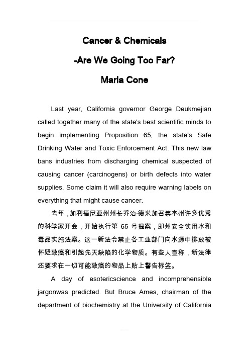
Cancer & Chemicals-Are We Going Too Far?Marla ConeLast year, California governor George Deukmejian called together many of the state's best scientific minds to begin implementing Proposition 65, the state's Safe Drinking Water and Toxic Enforcement Act. This new law bans industries from discharging chemical suspected of causing cancer (carcinogens) or birth defects into water supplies. Some claim it will also require warning labels on everything that might cause cancer.去年,加利福尼亚州州长乔治·德米加召集本州许多优秀的科学家开会,开始执行第65号提案,即州安全饮用水和毒品实施法案。
这一新法令禁止各工业部门向水源中排放被怀疑致癌和引起先天缺陷的化学物质。
有些人宣称,新法律还要求在一切可能致癌的物品上贴上警告标签。
A day of esotericscience and incomprehensible jargonwas predicted. But Bruce Ames, chairman of the department of biochemistry at the University of Californiaat Berkeley, had plans to liven the proceedings.原来预计,开会那天将全是些玄妙的科学和难懂的术语,但加州大学伯克利分校生物化学系系主任布鲁斯·爱姆兹却打算使会议开得更有生气。
研究生英语阅读教程翻译英汉对照

Lesson 11. For English is a killer. It is English that has killed off Cumbric, Cornish, Norn and Manx. There are still parts of these islands where sizeable communities speak languages that were there before English. Yet English is everywhere in everyday use and understood by all or virtually all, constituting such a threat to the three remaining Celtic languages, Irish, Scottish Gaelic, and Welsh... that their long-term future must be considered... very greatly at risk.因为英语是个杀手。
正是英语造成了康瑞克、康尼施、诺恩、曼科斯等语言的消亡。
在这些岛上还有相当多的人使用在英语到来之前就已存在的语言。
然而,英语在日常生活中无处不在。
所有的人或几乎所有的人都懂英语。
英语对现存的凯尔特语:爱尔兰语、苏格兰盖尔语及威尔士语的威胁是如此之大,它们的未来岌岌可危。
2. He also associated such policies with a prejudice which he calls linguisticism (a condition parallel to racism and sexism). As Phillipson sees it, leading institutions and individuals within the predominantly "white" English-speaking world, have (by design or default) encouraged or at least tolerated—and certainly have not opposed—the hegemonic spread of English, a spread which began some three centuries ago as economic and colonial expansion.同时,他认为这些政策和他称之为语言歧视(和种族歧视、性别歧视的情况类似)的偏见密切相关。
研究生英语下The Hidden Side of Happiness全文翻译

For personal use only in study and research; not forcommercial useThe Hidden Side of Happiness1、Hurricanes, house fires, cancer, white-water rafting accidents, plane crashes, vicious attacks in dark alleyways. Nobody asks for any of it. But to their surprise, many people find that enduring such a harrowing ordeal ultimately changes them for the better. Their refrain might go something like this: "I wish it hadn't happened, but I'm a better person for it."飓风、房屋失火、癌症、激流漂筏失事、坠机、昏暗小巷遭歹徒袭击,没人想找上这些事儿。
但出人意料的是,很多人发现遭受这样一次痛苦的磨难最终会使他们向好的方面转变。
他们可能都会这样说:“我希望这事没发生,但因为它我变得更完美了。
”2、We love to hear the stories of people who have been transformed by their tribulations, perhaps because they testify to a bona fide psychological truth, one that sometimes gets lost amid endless reports of disaster: There is a built-in human capacity to flourish under the most difficult circumstances. Positive reactions to profoundly disturbing experiences are not limited to the toughest or the bravest. In fact, roughly half the people who struggle with adversity say that their lives have in some ways improved.我们都爱听人们经历苦难后发生转变的故事,可能是因为这些故事证实了一条真正的心理学上的真理,这条真理有时会湮没在无数关于灾难的报道中:在最困难的境况中,人所具有的一种内在的奋发向上的能力会进发出来。
研究生外文文献翻译--中英完整版

Discussion about the application of the anchor bar on theslope constructionFu Ming Fu , Zhang TianAbstract:There are some advantages in strengthening slope with the anchor bar, such as low project cost, convenient for construction and so on. It not only meets the requirement of the reliability of the construction, but also is economic and reasonable for the construction.Key words: anchor bar; slope; strengthening1.IntroductionAnchor technique uses strata geotechnical’s shear strength around bolt to deliver structures pulling force or keep strata of the excavation own stability. Due to the use of the anchor rod, Anchor strata produce compressive zone and have reinforcement effect to strata, can enhance the strength of strata, improve mechanical properties of strata, make structure and stratum together formed a kind of work together complex. Anchor system can effectively sustain tension and shear, improve shear strength of the potential sliding surface, so it can effectively prevent slope to produce sliding damage.Fig 1 after excavation of the slope2.Project profileThe length of a slope is about 60m, the most slope height is about 23m,the angle up to 50°~ 75°, a five-layer frame structure buildings is far from about 1.5 to 4m at its base edge, its foundation is artificial bored pile and its bearing stratum is in weathered phyllite. Due to the strong weathering of rocks, it was chunky, loosely structured, multi-muddy filling. It has residual slope deposits of silty clay overlying and local folder with a pulpy, low strength. Slope hadcollapsed at various locations, it is vary dangerous to the building, so we need to reinforce the slope, and we use stone concrete retaining wall and bolt to support it.3.Bolt retaining and protecting design3.1Bolt design(1)all formation of anchor use whole length bond-type, the binder materials are ordinary cement mortar, the mortar strength grade is M30, the anchor length L is 10 meters, the slope height h is 9 meters. Anchoring section length is 5m.(2)According to the construction condition and the needs of the process, the layout form of anchor use quincunx, and in order to make the anchoring force in the role of surface rock surface with uniform, the two adjacent line bolts should be staggered arrangement.(3)The anchor’s number according to /3.24 per meter to calculation, the anchor length is L, a tolal of 252. The diameter of drilling holes is φ90,the number of drill according to (L-0.1)m per hole to calculation, M30 grout number according to average 0.052m3per hole to calculation.(4)The two adjacent rows vertical spacing of anchor take 2.55m, horizontal spacing take 2.55m. The dip angle of anchor: with the angle of horizontal line is 20°, and drilling down with this Angle.(5)Anchor use the steel bar, which is HRB400 level, 28mm diameter.3.2Anchor calculation(1)The calculation of lateral geotechnical pressure[1][2]When the supporting structure to leave in rock and earth mass direction migration until to the limit equilibrium state, the geotechnical pressure which is role in supporting structure called active geotechnical pressure. Its calculation method is as follows:For the slope which has no flare structure surface, generally speaking, failure is controled by rock mass strength, the calculation formula is same to the active soil pressure, but cohesive force C take zero, internal friction angle ϕuse eϕ(rock mass equivalent internal friction angle) instead of, according to the standard to selection; rupture angle is 45°+ϕ/2(ϕis rock mass internal friction angle, is estimationed by haircut at the standard of rock mass internal friction angle, reduction factor according to the standard to selection).According to the engineering survey, active rock pressure can calculation as follows:(2)the calculation of anchor tension design value a Q ak N N γ= (1)(2) In the formula: a N is anchor tension design value; ak N is anchor tension standard value; Q γis partial load factor, take 1.3; tk H is the horizontal tension standard value of anchor; αis the dip angle of anchor.Through the calculation, ak N =112.3kN a N =145.99kN(3)the calculation of anchor steel section area(3) In the formula: S A is the steel section area of anchor; ογ is slope engineering importance coefficient(the slope engineering importance coefficient of this project is level 1, take 1.1); 2ξis the tensile working conditions coefficient of anchor bar ( permanent anchor take 0.69, temporary anchor take 0.92); y f is the tensile strength design value of anchor bar(standard value k y f =400a MP , design value y f =360a MP ).According to the calculation, S A ≥0.5883210m -⨯,choose level 3 steel of 1φ28mm,S A =0.6153210m -⨯.(4)The calculation of anchorage body and rock mass anchoring lengthanchoring length should not only meet the requirements which the bond force of formation on mortar and the bond stress of mortar on steel, but also meet the requirements that the Structure design codes the Minimum anchoring length.(4) In the formula: a l is the anchoring length; D is the diameter of anchorage body; rb f is the bond strength eigenvalue of layer and anchorage body, through the experiment or local experience sure, or according to the standard to selection ( this engineering ’s rock mass uniaxial compressive 2222111209tan (45)2090.217175.77/2222e a aE H K kN m ϕγ︒==⨯⨯⨯-=⨯⨯⨯=cos tkak H N α=2a S yNA f ογξ≥1ak a rbN l Df ξπ≥strength is 7.46a MP , belong to soft rock, rock mass structural plane development, rb f take 300a KP );1ξis the bond working conditions coefficient of anchorage body and layer (permanent anchor take 1.00).According to the calculation, a l ≥4.3m, take a l =5.0m.(5)The anchoring length between anchor steel and anchor mortara l ≥ (5) In the formula: a l is the anchoring length between steel and mortar; d is the diameter of anchor bar; n is the number of steel;b f is the bond strength design value between steel and anchor mortar, through the experiment sure, or according to the standard take 2.40; 3ξ is the working conditions coefficient of steel and mortar bond strength(permanent anchor take 0.60). According to the calculation, a l ≥2.1m ,take a l =5.0m.3.3 The construction technology and key points of anchorThe anchor ’s construction technology is as follows: build-up scaffold ——excavate and clear up the slope surface ——measures to fix position ——drill hole ——washing hole ——bolt put in a certain place ——grout ——colligation the end of the anchor ——flushing the slope surface ——pouring frame space ——Spray seed(1)This slope belong to rocky slope, after excavate the slope 10 cm to the underside of the frame space, set bolt and pouring frame space, then spray grass or seeds after borrowed soil 20 cm in the frame space.(2)the slope should be payed attention to clean up, when construction. The anchor should be placed after wash hole, then put pressure (0.4MPa) and grout. After the mortar fully solidification, colligation steel, cast-in-place reinforced concrete frame space, bend the end of the anchor and bind point by point with the skeleton steel.(3)Before drilling, the hole should be measured to fix position and then do mark. Pitch deviation is less than 150mm, hole depth error is less than 50mm. Try not remold the surrounding rock, when drill. Before Put the anchor, it should be attentioned that blow wash clean the water of the hole and rock powder and so on, and rust removal the body of rod. When grouting, builders 3a bN n df ογξπshould attention the grouting pressure and mortar ratio.Fig 2 anchor field construction drawing4.ConclusionIt is economical to reinforcement slope with bolt, and use the normal equipment, It is not only achieve safe and also economy and rational.(1) Today bolt technology is widely used in the project. It is an effective reinforcement measures to constraints sliding soil with the combining of bolt and concrete slope protection.(2) We must be sure to do geological exploration work of the slope to find out the nature of the rock and hydrogeological situation before reinforcing slope by grouting bolt.(3) Due to the factors of engineering geological conditions, grouting pressure and construction technology, we should be given adequate attention to the quality of construction.Reference[1]Technical code for building slope engineering (JGJ 120-99). The People's Republic nationalstandards. Beijing: China Architecture & Building PRESS.[2] Ying-Ren Zheng, Zu-Yu Chen etc. Engineering Treatment of Slope & Landslide [M]. Beijing:China Communications Press,2007[3] LuoZhenHai. Talk shallowly the application of the anchor at the slope reinforcement[J]. FujianConstruction Science & Technology,2010,06:15-16浅谈锚杆技术在边坡工程中的应用 1.引言锚杆技术是利用锚杆周围地层岩土的抗剪强度来传递结构物的拉力或保持地层开挖面的自身稳定。
外国文献的中英文对照版

diabetes neuropathies: update on definitions,diagnostic criteria,estimation of severity,and treatments糖尿病神经病变:更新的定义,诊断标准,估计的严重程度,与治疗Tesfaye S,Boulton A J.Dyck P J,et al.内容概要,博尔顿一·戴克磷,等。
AbstractPreceding the joint meeting of the 19th annual Diabetic Neuropathy Study Group of the European Association for the Study of Diabetes (NEURODIAB) and the 8th International Symposium on Diabetic Neuropathy in Toronto, Canada, 13–18 October 2009, expert panels were convened to provide updates on classification, definitions, diagnostic criteria, and treatments of diabetic peripheral neuropathies (DPNs), autonomic neuropathy, painful DPNs, and structural alterations in DPNs.前联席会议第十九年糖尿病神经病变研究组欧洲糖尿病研究协会(neurodiab)和第八届国际糖尿病神经病变在多伦多,加拿大,–13 18 2009年十月,专家小组召开了提供更新的定义,分类,诊断标准,治疗糖尿病周围神经病变(标准草案),自主神经病变,痛苦的标准草案,和结构改变的标准草案。
外文文献及翻译doc
Criminal Law1.General IntroductionCriminal law is the body of the law that defines criminal offenses, regulates the apprehension, charging, and trial of suspected offenders,and fixes punishment for convicted persons. Substantive criminal law defines particular crimes, and procedural law establishes rules for the prosecution of crime. In a democratic society, it is the function of the legislative bodies to decide what behavior will be made criminal and what penalties will be attached to violations of the law.Capital punishment may be imposed in some jurisdictions for the most serious crimes. And physical or corporal punishment may still be imposed such as whipping or caning, although these punishments are prohibited in much of the world. A convict may be incarcerated in prison or jail and the length of incarceration may vary from a day to life.Criminal law is a reflection of the society that produce it. In an Islamic theocracy, such as Iran, criminal law will reflect the religious teachings of the Koran; in an Catholic country, it will reflect the tenets of Catholicism. In addition, criminal law will change to reflect changes in society, especially attitude changes. For instance, use of marijuana was once considered a serious crime with harsh penalties, whereas today the penalties in most states are relatively light. As severity of the penaltieswas reduced. As a society advances, its judgments about crime and punishment change.2.Elements of a CrimeObviously, different crimes require different behaviors, but there are common elements necessary for proving all crimes. First, the prohibited behavior designated as a crime must be clearly defined so that a reasonable person can be forewarned that engaging in that behavior is illegal. Second, the accused must be shown to have possessed the requisite intent to commit the crime. Third, the state must prove causation. Finally, the state must prove beyond a reasonable doubt that the defendant committed the crime.(1) actus reusThe first element of crime is the actus reus.Actus is an act or action and reus is a person judicially accused of a crime. Therefore, actus reus is literally the action of a person accused of a crime. A criminal statute must clearly define exactly what act is deemed “guilty”---that is, the exact behavior that is being prohibited. That is done so that all persons are put on notice that if they perform the guilty act, they will be liable for criminal punishment. Unless the actus reus is clearly defined, one might not know whether or not on e’s behavior is illegal.Actus reus may be accomplished by an action, by threat of action,or exceptionally, by an omission to act, which is a legal duty to act. For example, the act of Cain striking Abel might suffice, or a parent‟s failure to give to a young child also may provide the actus reus for a crime.Where the actus reus is a failure to act, there must be a duty of care. A duty can arise through contract, a voluntary undertaking, a blood relation, and occasionally through one‟s official position. Duty also can arise from one‟s own creation of a dangerous situation.(2)mens reaA second element of a crime is mens rea. Mens rea refers to an individual‟s state of mind when a crime is committed. While actus reus is proven by physical or eyewitness evidence, mens rea is more difficult to ascertain. The jury must determine for itself whether the accused had the necessary intent to commit the act.A lower threshold of mens rea is satisfied when a defendant recognizes an act is dangerous but decides to commit it anyway. This is recklessness. For instance, if Cain tears a gas meter from a wall, and knows this will let flammable gas escape into a neighbor‟s house, he could be liable for poisoning. Courts often consider whether the actor did recognise the danger, or alternatively ought to have recognized a danger (though he did not) is tantamount to erasing intent as a requirement. In this way, the importance of mens rea hasbeen reduced in some areas of the criminal law.Wrongfulness of intent also may vary the seriousness of an offense. A killing committed with specific intent to kill or with conscious recognition that death or serious bodily harm will result, would be murder, whereas a killing affected by reckless acts lacking such a consciousness could be manslaughter.(3)CausationThe next element is causation. Often the phrase “but for”is used to determine whether causation has occurred. For example, we might say “Cain caused Abel”, by which we really mean “Cain caused Abel‟s death. ”In other words, …but for Cain‟s act, Abel would still be alive.” Causation, then, means “but for” the actions of A, B would not have been harmed. In criminal law, causation is an element that must be proven beyond a reasonable doubt.(4) Proof beyond a Reasonable DoubtIn view of the fact that in criminal cases we are dealing with the life and liberty of the accused person, as well as the stigma accompanying conviction, the legal system places strong limits on the power of the state to convict a person of a crime. Criminal defendants are presumed innocent. The state must overcome this presumption of innocence by proving every element of the offense charged against the defendant beyond a reasonable doubt to thesatisfaction of all the jurors. This requirement is the primary way our system minimizes the risk of convicting an innocent person.The state must prove its case within a framework of procedural safeguards that are designed to protect the accused. The state‟s failure to prove any material element of its case results in the accused being acquitted or found not guilty, even though he or she may actually have committed the crime charged.3. Strict LiabilityIn modern society, some crimes require no more mens rea, and they are known as strict liability offenses. For in stance, under the Road Traffic Act 1988 it is a strict liability offence to drive a vehicle with an alcohol concentration above the prescribed limit.Strict liability can be described as criminal or civil liability notwithstanding the lack mens rea or intent by the defendant. Not all crimes require specific intent, and the threshold of culpability required may be reduced. For example, it might be sufficient to show that a defendant acted negligently, rather than intentionally or recklessly.1. 概述刑法是规定什么试犯罪,有关犯罪嫌疑人之逮捕、起诉及审判,及对已决犯处以何种刑罚的部门法。
外文文献翻译原文+译文
外文文献翻译原文Analysis of Con tin uous Prestressed Concrete BeamsChris BurgoyneMarch 26, 20051、IntroductionThis conference is devoted to the development of structural analysis rather than the strength of materials, but the effective use of prestressed concrete relies on an appropriate combination of structural analysis techniques with knowledge of the material behaviour. Design of prestressed concrete structures is usually left to specialists; the unwary will either make mistakes or spend inordinate time trying to extract a solution from the various equations.There are a number of fundamental differences between the behaviour of prestressed concrete and that of other materials. Structures are not unstressed when unloaded; the design space of feasible solutions is totally bounded;in hyperstatic structures, various states of self-stress can be induced by altering the cable profile, and all of these factors get influenced by creep and thermal effects. How were these problems recognised and how have they been tackled?Ever since the development of reinforced concrete by Hennebique at the end of the 19th century (Cusack 1984), it was recognised that steel and concrete could be more effectively combined if the steel was pretensioned, putting the concrete into compression. Cracking could be reduced, if not prevented altogether, which would increase stiffness and improve durability. Early attempts all failed because the initial prestress soon vanished, leaving the structure to be- have as though it was reinforced; good descriptions of these attempts are given by Leonhardt (1964) and Abeles (1964).It was Freyssineti’s observations of the sagging of the shallow arches on three bridges that he had just completed in 1927 over the River Allier near Vichy which led directly to prestressed concrete (Freyssinet 1956). Only the bridge at Boutiron survived WWII (Fig 1). Hitherto, it had been assumed that concrete had a Young’s modulus which remained fixed, but he recognised that the de- ferred strains due to creep explained why the prestress had been lost in the early trials. Freyssinet (Fig. 2) also correctly reasoned that high tensile steel had to be used, so that some prestress would remain after the creep had occurred, and alsothat high quality concrete should be used, since this minimised the total amount of creep. The history of Freyssineti’s early prestressed concrete work is written elsewhereFigure1:Boutiron Bridge,Vic h yFigure 2: Eugen FreyssinetAt about the same time work was underway on creep at the BRE laboratory in England ((Glanville 1930) and (1933)). It is debatable which man should be given credit for the discovery of creep but Freyssinet clearly gets the credit for successfully using the knowledge to prestress concrete.There are still problems associated with understanding how prestressed concrete works, partly because there is more than one way of thinking about it. These different philosophies are to some extent contradictory, and certainly confusing to the young engineer. It is also reflected, to a certain extent, in the various codes of practice.Permissible stress design philosophy sees prestressed concrete as a way of avoiding cracking by eliminating tensile stresses; the objective is for sufficient compression to remain after creep losses. Untensionedreinforcement, which attracts prestress due to creep, is anathema. This philosophy derives directly from Freyssinet’s logic and is primarily a working stress concept.Ultimate strength philosophy sees prestressing as a way of utilising high tensile steel as reinforcement. High strength steels have high elastic strain capacity, which could not be utilised when used as reinforcement; if the steel is pretensioned, much of that strain capacity is taken out before bonding the steel to the concrete. Structures designed this way are normally designed to be in compression everywhere under permanent loads, but allowed to crack under high live load. The idea derives directly from the work of Dischinger (1936) and his work on the bridge at Aue in 1939 (Schonberg and Fichter 1939), as well as that of Finsterwalder (1939). It is primarily an ultimate load concept. The idea of partial prestressing derives from these ideas.The Load-Balancing philosophy, introduced by T.Y. Lin, uses prestressing to counter the effect of the permanent loads (Lin 1963). The sag of the cables causes an upward force on the beam, which counteracts the load on the beam. Clearly, only one load can be balanced, but if this is taken as the total dead weight, then under that load the beam will perceive only the net axial prestress and will have no tendency to creep up or down.These three philosophies all have their champions, and heated debates take place between them as to which is the most fundamental.2、Section designFrom the outset it was recognised that prestressed concrete has to be checked at both the working load and the ultimate load. For steel structures, and those made from reinforced concrete, there is a fairly direct relationship between the load capacity under an allowable stress design, and that at the ultimate load under an ultimate strength design. Older codes were based on permissible stresses at the working load; new codes use moment capacities at the ultimate load. Different load factors are used in the two codes, but a structure which passes one code is likely to be acceptable under the other.For prestressed concrete, those ideas do not hold, since the structure is highly stressed, even when unloaded. A small increase of load can cause some stress limits to be breached, while a large increase in load might be needed to cross other limits. The designer has considerable freedom to vary both the working load and ultimate load capacities independently; both need to be checked.A designer normally has to check the tensile and compressive stresses, in both the top and bottom fibre of the section, for every load case. The critical sections are normally, but not always, the mid-span and the sections over piers but other sections may become critical ,when the cable profile has to be determined.The stresses at any position are made up of three components, one of which normally has a different sign from the other two; consistency of sign convention is essential.If P is the prestressing force and e its eccentricity, A and Z are the area of the cross-section and its elastic section modulus, while M is the applied moment, then where ft and fc are the permissible stresses in tension and compression.c e t f ZM Z P A P f ≤-+≤Thus, for any combination of P and M , the designer already has four in- equalities to deal with.The prestressing force differs over time, due to creep losses, and a designer isusually faced with at least three combinations of prestressing force and moment;• the applied moment at the time the prestress is first applied, before creep losses occur,• the maximum applied moment after creep losses, and• the minimum applied moment after creep losses.Figure 4: Gustave MagnelOther combinations may be needed in more complex cases. There are at least twelve inequalities that have to be satisfied at any cross-section, but since an I-section can be defined by six variables, and two are needed to define the prestress, the problem is over-specified and it is not immediately obvious which conditions are superfluous. In the hands of inexperienced engineers, the design process can be very long-winded. However, it is possible to separate out the design of the cross-section from the design of the prestress. By considering pairs of stress limits on the same fibre, but for different load cases, the effects of the prestress can be eliminated, leaving expressions of the form:rangestress e Perm issibl Range Mom entZ These inequalities, which can be evaluated exhaustively with little difficulty, allow the minimum size of the cross-section to be determined.Once a suitable cross-section has been found, the prestress can be designed using a construction due to Magnel (Fig.4). The stress limits can all be rearranged into the form:()M fZ PA Z e ++-≤1 By plotting these on a diagram of eccentricity versus the reciprocal of the prestressing force, a series of bound lines will be formed. Provided the inequalities (2) are satisfied, these bound lines will always leave a zone showing all feasible combinations of P and e. The most economical design, using the minimum prestress, usually lies on the right hand side of the diagram, where the design is limited by the permissible tensile stresses.Plotting the eccentricity on the vertical axis allows direct comparison with the crosssection, as shown in Fig. 5. Inequalities (3) make no reference to the physical dimensions of the structure, but these practical cover limits can be shown as wellA good designer knows how changes to the design and the loadings alter the Magnel diagram. Changing both the maximum andminimum bending moments, but keeping the range the same, raises and lowers the feasible region. If the moments become more sagging the feasible region gets lower in the beam.In general, as spans increase, the dead load moments increase in proportion to the live load. A stage will be reached where the economic point (A on Fig.5) moves outside the physical limits of the beam; Guyon (1951a) denoted the limiting condition as the critical span. Shorter spans will be governed by tensile stresses in the two extreme fibres, while longer spans will be governed by the limiting eccentricity and tensile stresses in the bottom fibre. However, it does not take a large increase in moment ,at which point compressive stresses will govern in the bottom fibre under maximum moment.Only when much longer spans are required, and the feasible region moves as far down as possible, does the structure become governed by compressive stresses in both fibres.3、Continuous beamsThe design of statically determinate beams is relatively straightforward; the engineer can work on the basis of the design of individual cross-sections, as outlined above. A number of complications arise when the structure is indeterminate which means that the designer has to consider, not only a critical section,but also the behaviour of the beam as a whole. These are due to the interaction of a number of factors, such as Creep, Temperature effects and Construction Sequence effects. It is the development of these ideas whichforms the core of this paper. The problems of continuity were addressed at a conference in London (Andrew and Witt 1951). The basic principles, and nomenclature, were already in use, but to modern eyes concentration on hand analysis techniques was unusual, and one of the principle concerns seems to have been the difficulty of estimating losses of prestressing force.3.1 Secondary MomentsA prestressing cable in a beam causes the structure to deflect. Unlike the statically determinate beam, where this motion is unrestrained, the movement causes a redistribution of the support reactions which in turn induces additional moments. These are often termed Secondary Moments, but they are not always small, or Parasitic Moments, but they are not always bad.Freyssinet’s bridge across the Marne at Luzancy, started in 1941 but not completed until 1946, is often thought of as a simply supported beam, but it was actually built as a two-hinged arch (Harris 1986), with support reactions adjusted by means of flat jacks and wedges which were later grouted-in (Fig.6). The same principles were applied in the later and larger beams built over the same river.Magnel built the first indeterminate beam bridge at Sclayn, in Belgium (Fig.7) in 1946. The cables are virtually straight, but he adjusted the deck profile so that the cables were close to the soffit near mid-span. Even with straight cables the sagging secondary momentsare large; about 50% of the hogging moment at the central support caused by dead and live load.The secondary moments cannot be found until the profile is known but the cablecannot be designed until the secondary moments are known. Guyon (1951b) introduced the concept of the concordant profile, which is a profile that causes no secondary moments; es and ep thus coincide. Any line of thrust is itself a concordant profile.The designer is then faced with a slightly simpler problem; a cable profile has to be chosen which not only satisfies the eccentricity limits (3) but is also concordant. That in itself is not a trivial operation, but is helped by the fact that the bending moment diagram that results from any load applied to a beam will itself be a concordant profile for a cable of constant force. Such loads are termed notional loads to distinguish them from the real loads on the structure. Superposition can be used to progressively build up a set of notional loads whose bending moment diagram gives the desired concordant profile.3.2 Temperature effectsTemperature variations apply to all structures but the effect on prestressed concrete beams can be more pronounced than in other structures. The temperature profile through the depth of a beam (Emerson 1973) can be split into three components for the purposes of calculation (Hambly 1991). The first causes a longitudinal expansion, which is normally released by the articulation of the structure; the second causes curvature which leads to deflection in all beams and reactant moments in continuous beams, while the third causes a set of self-equilibrating set of stresses across the cross-section.The reactant moments can be calculated and allowed-for, but it is the self- equilibrating stresses that cause the main problems for prestressed concrete beams. These beams normally have high thermal mass which means that daily temperature variations do not penetrate to the core of the structure. The result is a very non-uniform temperature distribution across the depth which in turn leads to significant self-equilibrating stresses. If the core of the structure is warm, while the surface is cool, such as at night, then quite large tensile stresses can be developed on the top and bottom surfaces. However, they only penetrate a very short distance into the concrete and the potential crack width is very small. It can be very expensive to overcome the tensile stress by changing the section or the prestress。
(完整word版)外文文献及翻译doc

Criminal Law1.General IntroductionCriminal law is the body of the law that defines criminal offenses, regulates the apprehension, charging, and trial of suspected offenders,and fixes punishment for convicted persons. Substantive criminal law defines particular crimes, and procedural law establishes rules for the prosecution of crime. In a democratic society, it is the function of the legislative bodies to decide what behavior will be made criminal and what penalties will be attached to violations of the law.Capital punishment may be imposed in some jurisdictions for the most serious crimes. And physical or corporal punishment may still be imposed such as whipping or caning, although these punishments are prohibited in much of the world. A convict may be incarcerated in prison or jail and the length of incarceration may vary from a day to life.Criminal law is a reflection of the society that produce it. In an Islamic theocracy, such as Iran, criminal law will reflect the religious teachings of the Koran; in an Catholic country, it will reflect the tenets of Catholicism. In addition, criminal law will change to reflect changes in society, especially attitude changes. For instance, use of marijuana was once considered a serious crime with harsh penalties, whereas today the penalties in most states are relatively light. As severity of the penaltieswas reduced. As a society advances, its judgments about crime and punishment change.2.Elements of a CrimeObviously, different crimes require different behaviors, but there are common elements necessary for proving all crimes. First, the prohibited behavior designated as a crime must be clearly defined so that a reasonable person can be forewarned that engaging in that behavior is illegal. Second, the accused must be shown to have possessed the requisite intent to commit the crime. Third, the state must prove causation. Finally, the state must prove beyond a reasonable doubt that the defendant committed the crime.(1) actus reusThe first element of crime is the actus reus.Actus is an act or action and reus is a person judicially accused of a crime. Therefore, actus reus is literally the action of a person accused of a crime. A criminal statute must clearly define exactly what act is deemed “guilty”---that is, the exact behavior that is being prohibited. That is done so that all persons are put on notice that if they perform the guilty act, they will be liable for criminal punishment. Unless the actus reus is clearly defined, one might not know whether or not on e’s behavior is illegal.Actus reus may be accomplished by an action, by threat of action,or exceptionally, by an omission to act, which is a legal duty to act. For example, the act of Cain striking Abel might suffice, or a parent’s failure to give to a young child also may provide the actus reus for a crime.Where the actus reus is a failure to act, there must be a duty of care. A duty can arise through contract, a voluntary undertaking, a blood relation, and occasionally through one’s official position. Duty also can arise from one’s own creation of a dangerous situation.(2)mens reaA second element of a crime is mens rea. Mens rea refers to an individual’s state of mind when a crime is committed. While actus reus is proven by physical or eyewitness evidence, mens rea is more difficult to ascertain. The jury must determine for itself whether the accused had the necessary intent to commit the act.A lower threshold of mens rea is satisfied when a defendant recognizes an act is dangerous but decides to commit it anyway. This is recklessness. For instance, if Cain tears a gas meter from a wall, and knows this will let flammable gas escape into a neighbor’s house, he could be liable for poisoning. Courts often consider whether the actor did recognise the danger, or alternatively ought to have recognized a danger (though he did not) is tantamount to erasing intent as a requirement. In this way, the importance of mens rea hasbeen reduced in some areas of the criminal law.Wrongfulness of intent also may vary the seriousness of an offense. A killing committed with specific intent to kill or with conscious recognition that death or serious bodily harm will result, would be murder, whereas a killing affected by reckless acts lacking such a consciousness could be manslaughter.(3)CausationThe next element is causation. Often the phrase “but for”is used to determine whether causation has occurred. For example, we might say “Cain caused Abel”, by which we really mean “Cain caused Abel’s death. ”In other words, ‘but for Cain’s act, Abel would still be alive.” Causation, then, means “but for” the actions of A, B would not have been harmed. In criminal law, causation is an element that must be proven beyond a reasonable doubt.(4) Proof beyond a Reasonable DoubtIn view of the fact that in criminal cases we are dealing with the life and liberty of the accused person, as well as the stigma accompanying conviction, the legal system places strong limits on the power of the state to convict a person of a crime. Criminal defendants are presumed innocent. The state must overcome this presumption of innocence by proving every element of the offense charged against the defendant beyond a reasonable doubt to thesatisfaction of all the jurors. This requirement is the primary way our system minimizes the risk of convicting an innocent person.The state must prove its case within a framework of procedural safeguards that are designed to protect the accused. The state’s failure to prove any material element of its case results in the accused being acquitted or found not guilty, even though he or she may actually have committed the crime charged.3. Strict LiabilityIn modern society, some crimes require no more mens rea, and they are known as strict liability offenses. For in stance, under the Road Traffic Act 1988 it is a strict liability offence to drive a vehicle with an alcohol concentration above the prescribed limit.Strict liability can be described as criminal or civil liability notwithstanding the lack mens rea or intent by the defendant. Not all crimes require specific intent, and the threshold of culpability required may be reduced. For example, it might be sufficient to show that a defendant acted negligently, rather than intentionally or recklessly.1. 概述刑法是规定什么试犯罪,有关犯罪嫌疑人之逮捕、起诉及审判,及对已决犯处以何种刑罚的部门法。
研究生英语系列教材上unit4 原文翻译

The following text is extracted from Marriages and Families by Nijole V.Benokraitis.下面的文章选自奈杰尔贝诺克瑞提斯的婚姻与家庭。
The book has been used as a textbook for sociology courses and women's studies in a number of universities in the United States.此书在美国的一些大学里被用作社会学和妇女研究等课程的教材,It highlights important contemporary changes in society and the family它强调了在当代社会和家庭中所发生的重要变化,and explores the choices that are available to family members,探索了家庭成员所面临的选择,as well as the constraints that many of us do not recognize.以及我们很多人都还未意识到的种种约束。
It examines the diversity of American families today,该书还审视了当今美国家庭的多样性,using cross-cultural and multicultural comparisons运用跨文化和多元文化的比较,to encourage creative thinking about the many critical issues that confront the family of the twenty-first century.以激发创造性思维来研究21世纪家庭所面临的许多严峻问题。
LOVE AND LOVING RELATIONSHIPS爱和情感连系Nijole V.Benokraitis奈杰尔·贝诺克瑞提斯Love — as both an emotion and a behavior — is essential for human survival.爱,对于人类的生存是不可或缺的。
外文文献及翻译
英文原文:Rehabilitation of rectangular simply supported RC beams with shear deficiencies using CFRP compositesAhmed Khalifa a,* , Antonio Nanni ba Department of Structural Engineering, University of Alexandria, Alexandria 21544, Egyptb Department of Civil Engineering, University of Missouri at Rolla, Rolla, MO 65409, USAReceived 28 April 1999; received in revised form 30 October 2001; accepted 10 January 2002AbstractThe present study examines the shear performance and modes of failure of rectangular simply supported reinforced concrete(RC) beams designed with shear deficiencies. These members were strengthened with externally bonded carbon fiber reinforced polymer (CFRP) sheets and evaluated in the laboratory. The experimental program consisted of twelve full-scale RC beams tested to fail in shear. The variables investigated within this program included steel stirrups, and the shear span-to-effective depth ratio, as well as amount and distribution of CFRP. The experimental results indicated that the contribution of externally bonded CFRP to the shear capacity was significant. The shear capacity was also shown to be dependent upon the variables investigated. Test results were used to validate a shear design approach, which showed conservative and acceptable predictions.○C2002 Elsevier Science Ltd. All rights reserved.Keywords: Rehabilitation; Shear; Carbon fiber reinforced polymer1. IntroductionFiber reinforced polymer (FRP) composite systems, composed of fibers embedded in a polymeric matrix, can be used for shear strengthening of reinforced con-crete (RC) members [1–7]. Many existing RC beams are deficient and in need of strengthening. The shear failure of an RC beam is clearly different from its flexural failure. In shear, the beam fails suddenly without sufficient warning and diagonal shear cracks are consid-erably wider than the flexural cracks [8].The objectives of this program were to:1. Investigate performance and mode of failure of simply supported rectangular RC beams with shear deficien-cies after strengthening with externally bonded CFRP sheets.2. Address the factors that influence shear capacity of strengthened beams such as: steel stirrups, shear span-to-effective depth ratio (a/d ratio), and amount and distribution of CFRP.3. Increase the experimental database on shear strength-ening with externally bonded FRP reinforcement.4. Validate the design approach previously proposed by the authors [9].For these objectives, 12 full-scale, RC beams designed to fail in shear were strengthened with different CFRP schemes. These members were tested as simple beams using a four-point loading configuration with two different a/d ratios.2. Experimental program2.1. Test specimens and materialsTwelve full-scale beam specimens with a total span of 3050 mm. and a rectangular cross-section of 150-mm-wide and 305-mm-deep were tested. The specimens were grouped into two main series designated SW and SO depending on the presence of steel stirrups in the shear span of interest.Series SW consisted of four specimens. The details and dimensions of the specimens designated series SW are illustrated in Fig. 1a. In this series, four 32-mm steel bars were used as longitudinal reinforcement with two at top and two at bottom face of the cross-section to induce a shear failure. The specimens were reinforced with 10-mm steel stirrups throughout their entire span. The stirrups spacing in the shear span of interest, right half, was selected to allow failure in that span.Series SO consisted of eight beam specimens, which had the same cross-section dimension and longitudinal steel reinforcement as for series SW. No stirrups were provided in the test half span as illustrated in Fig. 1b.Each main series (i.e. series SW and SO) was subdivided into two subgroups according to shear span-to-effective depth ratio. This was selected to be a/d = 3 and 4, resulting in the following four subgroups: SW3;SW4; SO3; and SO4.The mechanical properties of the materials used for manufacturing the test specimens are listed in Table 1.Fabrication of the specimens including surface preparation and CFRP installation is described elsewhere [10].Table 12.2. Strengthening schemesOne specimen from each series (SW3-1, SW4-1, SO3-1 and SO4-1) was left without strengthening as a control specimen, whereas eight beam specimens were strengthened with externally bonded CFRP sheets following three different schemes as illustrated in Fig. 2.In series SW3, specimen SW3-2 was strengthened with two CFRP plies having perpendicular fiber directions (90°/0°). The first ply was attached in the form of continuous U-wrap with the fiber direction oriented perpendicular to the longitudinal axis of the specimen (90°). The second ply was bonded on the two sides of the specimen with the fiber direction parallel to the beam axis(0°).This ply [i.e. 0°ply] was selected to investigate the impact of additional horizontal restraint on shear strength.In series SW4, specimen SW4-2 was strengthened with two CFRP plies having perpendicular fiber direction (90°/0°) as for specimen SW3-2.Four beam specimens were strengthened in series SO3. Specimen SO3-2 was strengthened with one-ply CFRP strips in the form of U-wrap with 90°-fiber orientation. The strip width was 50 mm with center-to-center spacing of 125 mm. Specimen SO3-3 was strengthened in a manner similar to that of specimen SO3-2, butwith strip width equal to 75 mm. Specimen SO3-4 was strengthened with one-ply continuous U-wrap (90°). Specimen SO3-5 was strengthened with twoCFRP plies (90°/0°) similar to specimens SW3-2 and SW4-2.In series SO4, two beam specimens were strengthened. Specimen SO4-2 was strengthened with one-ply CFRP strips in the form of U-wrap similar to specimen SO3-2. Specimen SO4-3 was strengthened with one-ply continuous U-wrap (90°) similar to SO3-4.Fig. 1. Configuration and reinforcement details for beam specimens.Fig. 2. Schematic representation of CFRP strengthening schemes.2.3. Test set-up and instrumentationAll specimens were tested as simple span beams subjected to a four-point load as illustrated in Fig. 3. A universal testing machine with 1800 KN capacity was used in order to apply a concentrated load on a steel distribution beam used to generate the two concentrated loads. The load was applied progressively in cycles, usually one cycle before cracking followed by three cycles with the last one up to ultimate. The applied load vs. deflection curves shown in this paper are the envelopes of these load cycles.Four linear variable differential transformers (LVDTs) were used for each test to monitor vertical displacements at various locations as shown in Fig. 3. Two LVDTs were located at mid-span on each side of the specimen. The other two were located at the specimen supports to record support settlement.Fig.3. Schematic representation of test set-up for specimen (a) SW3-1, and (b) SW3-2.For each specimen of series SW, six strain gauges were attached to three stirrups to monitor the stirrup strain during loading as illustrated in Fig. 1a. Three strain gauges were attached directly to the FRP sheet on the sides of each strengthened beam to monitor strain variation in the FRP. The strain gauges were oriented in the vertical direction and located at the section mid-height with distances of 175, 300 and 425 mm, respectively, from the support for series SW3 and SO3. For beam specimens of series SW4 and SO4, the strain gauges were located at distance of 375, 500 and 625 mm, respectively, from the support.3. Results and discussionIn the following discussion, reference is always made to weak shear span or span of interest.3.1. Series SW3Shear cracks in the control specimen SW3-1 were observed close to the middle of the shear span when the load reached approximately 90 kN. As the load increased, additional shear cracks formed throughout, widening and propagating up to final failure at a load of 253 kN (see Fig. 4a).In specimen SW3-2 strengthened with CFRP (90°/0°), no cracks were visible on the sides or bottom of the test specimen due to the FRP wrapping. However,a longitudinal splitting crack initiated on the top surface of the beam at a high load of approximately 320 kN.Fig. 4. Failure modes of series SW3 specimens.The crack initiated at the location of applied load and extended towards the support. The specimen failed by concrete splitting (see Fig. 4b) at total load of 354 kN. This was an increase of 40% in ultimate capacity compared to the control specimen SW3-1. The splitting failure was due to the relatively high longitudinal compressive stress developed at top of the specimen, which created a transverse tension, led to the splitting failure. In addition, the relatively large amount of longitudinal steel reinforcement combined with over-strengthening for shear by CFRP wrap probably caused this mode of failure. The load vs. mid-span deflection curves for specimens SW3-1 and SW3-2 are illustrated in Fig. 5, to show the additional capacity gained byCFRP.Fig. 5. Applied load vs. mid-span deflection for series SW3 specimens.The maximum CFRP vertical strain measured at failure in specimen SW3-2 was approximately 0.0023 mm/mm, which corresponded to 14% of the reported CFRP ultimate strain. This value is not an absolute because it greatly depends on the location of the strain gauges with respect to a crack. However, the recorded strain indicates that if the splitting did not occur, the shear capacity could have reached higher load.Comparison between measured local stirrup strains in specimens SW3-1 and SW3-2 are shown in Fig. 6. The stirrups 1, 2 and 3 were located at distance of 175, 300 and 425 mm from the support, respectively. The results showed that the stirrups 2 and 3 did not yield at ultimate for both specimens. The strains (and the forces) in the stirrups of specimen SW3-2 were, in general, smaller than those of specimen SW3-1 at the same level of loading due to the effect of CFRP.Fig. 6. Applied load vs. strain in the stirrups for specimens SW3-1 and SW3-2.3.2. Series SW4In specimen SW4-1, the first diagonal crack was formed in the member at a total applied load of 75 kN. As the load increased, additional shear cracks appeared throughout the shear span. Failure of the beam occurred when the total applied load reached 200 kN. This was a decrease of 20% in shear capacity compared to the specimen SW3-1 with a/d ratio=3.Fig. 7. Applied load vs. mid-span deflection for series SW4 specimens.In specimen SW4-2, the failure was controlled by concrete splitting similar to test specimen SW3-2. The total applied load at ultimate was 361 kN with an 80% increase in shear capacity compared to the control specimen SW4-1. In addition, the measured strains in the stirrups for specimen SW4-2 were less than those of specimen SW4-1. The applied load vs. mid-span deflection curves for beams SW4-1 and SW4-2 are illustrated in Fig. 7. It may be noted that specimen SW4-2 resulted in greater deflection when compared to specimen SW4-1.When comparing the test results of series SW3 specimens to that of series SW4, the ultimate failure load of specimen SW3-2 and SW4-2 was almost the same. However, the enhanced capacity of specimen SW3-2 (a/d=3) due to the addition of the CFRP reinforcement was 101 kN, while specimen SW4-2 (a/d=4) was 161 kN. This indicates that the contribution of external CFRP reinforcement may be influenced by the ayd ratio and appears to decrease with a decreasing a/d ratio. Further, for both strengthened specimens (SW3-2 and SW4-2), CFRP sheets did not fracture or debond from the concrete surface at ultimate and this indicates that CFRP could provide additional strength if the beams did not failed by splitting.3.3. Series SO3Fig. 8 illustrates the failure modes for series SO3 specimens. Fig. 9 details the applied load vs. mid-span deflection for the specimens.The failure mode of control specimen SO3-1 was shear compression. Failure of the specimen occurred at a total applied load of 154 kN. This load was a decrease of shear capacity by 54.5 kN compared to the specimen SW3-1 due to the absent of the steel stirrups. In addition, the crack pattern in specimen SW3-1 was different from of specimen SO3-1. In specimen SW3-1, the presence of stirrups provided a better distribution of diagonal cracks throughout the shear span.In specimen SO3-2, strengthened with 50-mm CFRP strips spaced at 125 mm, the first diagonal shear crack was observed at an applied load of 100 kN. The crack propagated as the load increased in a similar manner to that of specimen SO3-1. Sudden failure occurred due to debonding of the CFRP strips over the diagonal shear crack, with spalled concrete attached to the CFRP strips. The total ultimate load was 262 kN with a 70% increase in shear capacity over the control specimen SO3-1. The maximum local CFRP vertical strain measured at failure in specimen SO3-2 was 0.0047 mm/mm (i.e. 28% of the ultimate strain), which indicated that the CFRP did not reach its ultimate.Specimen SO3-3, strengthened with 75-mm CFRP strips failed as a result of CFRP debonding at a total applied load of 266 kN. No significant increase in shear capacity was noted compared to specimen SO3-2. The maximum-recorded vertical CFRP strain at failure was 0.0052 mmymm (i.e. 31% of the ultimate strain).Specimen SO3-4, which was strengthened with a continuous CFRP U-wrap (908), failed as a result of CFRP debonding at an applied load of 289 kN. Results show that specimen SO3-4 exhibited increase in shear capacity of 87, 10 and 8.5% over specimens SO3-1,SO3-2 and SO3-3, respectively. Applied load vs. vertical CFRP strain for specimen SO3-4 is illustrated in Fig. 10 in which strain gauges sg1, sg2 and sg3 were located at mid-height with distances of 175, 300 and 425 mm from the support, respectively. Fig.10 shows that the CFRP strain was zero prior to diagonal crack formation, thenincreased slowly until the specimen reached a load in the neighborhood of the ultimate strength of the control specimen. At this point, the CFRP strain increased significantly until failure. The maximum local CFRP vertical strain measured at failure was approxi- mately 0.0045 mm/mm.When comparing the results of beams SO3-4 and SO3-2, the CFRP amount used to strengthen specimen SO3-4 was 250% of that used for specimen SO3-2. Only a 10% increase in shear capacity was achieved for the additional amount of CFRP used. This means that if an end anchor to control FRP debonding is not used, there is an optimum FRP quantity, beyond which the strengthening effect is questionable. A previous study[11] showed that by using an end anchor system, the failure mode of FRP debonding could be avoided. Reported findings are consistent with those of other research [7], which was based on a review of the experimental results available in the literature, and indicated that the contribution of FRP to the shear capacity increases almost linearly, with FRP axial rigidity expressed by f f E ρ(f ρ is the FRP area fraction and f E is the FRP elastic modulus) up to approximately 0.4 GPa. Beyond this value, the effectiveness of FRP ceases to be positive.In specimen SO3-5, the use of a horizontal ply over the continuous U-wrap (i.e. 90°/0°) resulted in a concrete splitting failure rather than a CFRP debonding failure. The failure occurred at total applied load of 339 kN with a 120% increase in the shear capacity compared to the control specimen SO3-1. The strengthening with two perpendicular plies (i.e. 90°/0°) resulted in a 17% increase in shear capacity compared to the specimen with only one CFRP ply in 90° orientation (i.e. specimen SO3-4). The maximum local CFRP vertical strain measured at failure was 0.0043 mm/mm.By comparing the test results of specimens SW3-2 and SO3-5, having the same a/d ratio and strengthening schemes but with different steel shear reinforcement, the shear strength (i.e. 177 and 169.5 kN for specimens SW3-2 and SO3-5, respectively), and the ductility are almost identical. One may conclude that the contribution of CFRP benefits the beam capacity to a greater degree for beams without steel shear reinforcement than for beams with adequate shear reinforcement.Fig. 8. Failure modes of series SO3 specimens.Fig. 9. Applied load vs. mid-span deflection for series SO3 specimens.Fig. 10. Measured vertical CFRP strain for specimen SO3-4.3.4. Series SO4Series SO4 exhibited the largest increase in shear capacity compared to the other series investigated with this research study. The experimental results in terms of applied load vs mid-span deflection for this series is illustrated in Fig. 11.The control specimen SO4-1 failed as a result of shear compression at a total applied load of 130 kN. Specimen SO4-2, strengthened with CFRP strips, the failure was controlled by CFRP debonding at a total load of 255 kN with 96% increase in shear capacity over the control specimen SO4-1. The maximum local CFRP vertical strain measured at failure was 0.0062mmymm.When comparing the test results of specimen SO4-2 to that of specimen SO3-2, theenhanced shear capacity of specimen SO4-2 (a/d=4) due to addition of CFRP strips was 62.5 kN, while specimen SO3-2 (a/d=3) resulted in added shear capacity of 54 kN. As expected, the contribution of CFRP reinforcement to resist the shear appeared to decrease with decreasing a/d ratio. Specimen SO4-3, strengthened with continuous U- wrap, failed as a result of concrete splitting at an applied load of 310 kN with a 138% increase in shear capacity compared to that of specimen SO4-1. The maximum local CFRP vertical strain measured at failure was 0.0037 mm/mm.4. Design approachThe design approach for computing the shear capacity of RC beams strengthened with externally bonded CFRP reinforcement, expressed in ACI design code [12] format, was proposed and published in 1998 [13]. The design model described two possible failure mechanisms of CFRP reinforcement namely: CFRP fracture; and CFRP debonding. Furthermore, two limits on the contribution of CFRP shear were proposed. The first limit was set to control the shear crack width and loss of aggregate interlock, and the second was to preclude web crushing. Also, the concrete strength and CFRP wrap- ping schemes were incorporated as design parameters. In recent study [9,10], modifications were proposed to the 1998 design approach to include results of a new study on bond mechanism between CFRP sheets and concrete surface [14]. In addition, the model was extended to provide the shear design equations in Eurocode as well as ACI format. Comparing with all test results available in the literature to date, 76 tests, the design approach showed acceptable and conservative estimates [10,13]. In this section, the summary of the design approach is presented. The comparison between experimental results and the calculated factored shear strength demonstrates the ability of the design approach to predict the shear capacity of the strengthened beams. demonstrates the ability of the design approach to predict the shear capacity of the strengthened beams.Fig. 11. Applied load vs. mid-span deflection for series SO4 specimens.Fig. 12. Dimensions used to define the area of FRP (a) vertical oriented FRP strips, and (b)inclined strips.4.1. Summary of the shear design approach — ACI formatIn traditional shear design (including the ACI Code), the nominal shear strength of an RC section is the sum of the nominal shear strengths of concrete and steel shear reinforcement. For beams strengthened with externally bonded FRP reinforcement, the shear strength may be computed by the addition of a third term to account of the FRP contribution. This is expressed as follows:φ, is obtained by multiplying the nominal shear The design shear strength,n Vstrength by a strength reduction factor for shear,φ. It was suggested that the reductionfactor φ=0.85 given in ACI [12] be main-tained for the concrete and steel terms. However, a more stringent strength reduction factor of 0.7 for the CFRP contribution was suggested w10x. This is due to the relative novelty of this repair technique. Thus,the design shear strength is expressed as follows.4.2. Contribution of CFRP reinforcement to the shear capacityThe expression used to compute shear contribution of CFRP reinforcement is given in Eq. (3). This equation is similar to that for shear contribution of steel stirrups and consistent with the ACI format.The area of CFRP shear reinforcement, f A , is the total thickness of the sheet (usually f t 2or sheets on both sides of the beam) times the width of the CFRP strip f ω. The dimensions used to define the area of CFRP in addition to the spacingf s and the effective depth of CFRP,f d , are shown in Fig. 12. Note that for continuous vertical shear reinforcement, the spacing of the strip,f s , and the width of the strip, f ω, areequal. In Eq. (3), an effective average CFRP stressfe f , smaller than its ultimate strength,fu f , was used to replace the yield stress of steel. At the ultimate limit state for the member in shear, it is not possible to attain the full strength of the FRP [7,13]. Failure is governed by either fracture of the FRP sheet at average stress levels well below FRP ultimate capacity due to stress concentrations, debonding of the FRP sheet from the concrete surface, or a significant decrease in the post- cracking concrete shear strength from a loss of aggregate interlock. Thus, the effective average CFRP stress is computed by applying a reduction coefficient, R, to the CFRP ultimate strength as expressed in Eq. (4).The reduction coefficient depends on the possible failure modes (either CFRP fracture or CFRP debonding). In either case, an upper limit for the reduction coefficient is established in order to control shear crack width and loss of aggregateinterlock.4.3. Reduction coefficient based on CFRP sheet fracture failureThe proposed reduction coefficient was calibrated on all available test results to date, 22 tests with failure controlled by CFRP fracture [10,13]. The reduction coefficient was established as a function off f E ρ (where f ρis the area fraction of CFRP) and expressed in Eq.(5) for ≤f f E ρ0.7 GPa.4.4. Reduction coefficient based on CFRP debonding failureThe shear capacity governed by CFRP debonding from the concrete surface was presented [9,10]as a function of CFRP axial rigidity, concrete strength, effective depth of CFRP reinforcement, and bonded surface configurations. In determining the reduction coefficient for bond, the effective bond length, e L , has to be determined first. Based on analytical and experimental data from bond tests, Miller [14] showed that the effective bond length slightly increases as CFRP axial rigidity,f f E t , increases. However, he suggested a constant conservative value e L for equal to 75 mm. The value may be modified when more bond tests data becomes available.After a shear crack develops, only that portion of the width of CFRP extending past the crack by the effective bonded length is assumed to be capable of carrying shear.[13] The effective width, fe W , based on the shear crack angle of 45°, and the wrapping scheme is expressed in Eqs. (6a) and (6b);if the sheet in the form of a U-wrap (6a)if the sheet is bonded only to the sides of the beam. (6b)The final expression for the reduction coefficient, R, for the mode of failure controlled by CFRP debonding is expressed in Eq. (8)Eq. (7) is applicable for CFRP axial rigidity, f f E t , ranging from 20 to 90 mm-GPa (kN/mm). Research into quantifying the bond characteristics for axial rigidities above90 mm·GPa is being conducted at the University of Missouri, Rolla (UMR).4.5. Upper limit of the reduction coefficientIn order to control the shear crack width and loss of aggregate interlock, an upper limit of reduction coefficient, R, was suggested and calibrated with all of the available test results [10] to be equal to fu ε/006.0where fu εis the ultimate tensile CFRP strain. This limit is such that the average effective strain in CFRP materials at ultimate can not be greater than 0.006 mm/mm (without the strengthening reduction factor,φ).4.6. Controlling reduction coefficientThe final controlling reduction coefficient for the CFRP system is taken as the lowest value determined from the two possible modes of failure and the upper limit. Note that if the sheet is wrapped entirely around the beam or an effective end anchor is used, the failure mode of CFRP debonding is not to be considered. The reduction coefficient is only controlled by FRP fracture and the upper limit.4.7. CFRP spacing requirementsSimilar to steel shear reinforcement, and consistent with ACI provision for the stirrups spacing[12], the spacing of FRP strips should not be so wide as to allow the formation of a diagonal crack without intercepting a strip. For this reason, if strips are used, they should not be spaced by more than the maximum given in Eq. (8).4.8. Limit on total shear reinforcementACI 318M-95 [12] 11.5.6.7 and 11.5.6.8 set a limit on the total shear strength that may be provided by more than one type of shear reinforcement to preclude the web crushing. FRP shear reinforcement should be included in this limit. A modification to ACI 318M-95 Section 11.5.6.8 was suggested as follows:4.9. Shear capacity of a CFRP strengthened section — Eurocode formatThe proposed design equation wEq. (3)x for computing the contribution of externally bonded CFRP reinforcement may be rewritten in Eurocode (EC2 1992) [15] format as Eq. (10).In this equation, the partial safety factor for CFRP materials,f , was suggestedequal to 1.3 [10].4.10. Comparison between the test results and calculated values The test summary and the comparison between the test results and the calculated shear strength, using the design approach (ACI format), are detailed in Tables 2 and 3, respectively. For CFRP strengthened beams, the measured contribution of concrete, Vc , and steel stirrups, Vs, (when present) were considered equal to the shearstrength of a non-strengthened beam. The nominal shear strength provided by concrete and steel stirrups was computed using Equations (11-5) and (11-15) in ACI- 318-95 [12]. In Equation (11-5), the values of Vu and M u were taken at the point of application of the load. The comparison indicates that the design approach gives conservative results for the strengthened beams as illus-trated in Fig. 13.5. Conclusions and further recommendationAn experimental investigation was conducted to study the shear behavior and the modes of failure of simply supported rectangular section RC beams with shear deficiencies, strengthened with CFRP sheets. The parameters investigated in this program were existence of steel shear reinforcement, shear span-to-effective depth ratio (ayd ratio), and CFRP amount and distribution.The results confirm that the strengthening technique using CFRP sheets can be used to increase significantly shear capacity, with efficiency that varies depending on the tested variables. For the beams tested in this program, increases in shear strength of 40–138% were achieved.Conclusions that emerged from this study may be summarized as follows:● The contribution of externally CFRP reinforcement to the shear capacity isinfluenced by the a/d ratio.● Increasing the amount of CFRP may not result in a proportional increase in theshear strength. The CFRP amount used to strengthen specimen SO3-4 was 250%。
外文文献原稿及译文
外文文献原稿和译文原稿About Programmable Logiccontrollers(PLCs)PLCs (programmable controller) is used in a variety of automatic control system and process control hub.They contain multiple input and output, input and output is used to transistors and other circuit, analog switch and relay to control the equipment.PLC software interface, standard calculator interface, specialized language programming and network equipment.Programmable logic controller I/O channel rules including all input output contact and contact, to expand capacity and the largest number of channels.Contact number is the sum of input and output points.PLC can specify any combination of these values.Extension units can be stack or connected to each other to increase the total control.The largest number of channels are in an extension system, the total number of maximum input and output channels.PLC system rules include scanning time, number of instructions, data storage and storage program.Scan time is used to monitor input and output module of PLC need time.Standard operation instruction is used in PLC software.Data storage is the ability to store data.Program memory is the ability to control software.Used for programmable controller input devices including DC, AC, intermediate relay, thermocouple, RTD, frequency or pulse, transistors and interrupt signal input;Output devices include DC, AC, intermediate relay, frequency or pulse, transistor, three-terminal two-way thyristor switch components;PLC programming equipment including control panel, handle and computer.Programmable control is used to control a variety of software programming language.These languages including iec61131-3, sequential table (SFC), action block diagram (FBD), ladder diagram (LD), and the structure of the text (ST), instruction sequences (IL), relay ladder diagram (RIL), flow charts, C language and Basic language.Iec61131-3 programming environment can support five languages, with international standards to regulate, SFC, respectively, FBD, LD, ST and IL.This allows more vendor compatibility and a variety of languages.SFC is a kind of graphlanguage, it provides the programming in order to cooperate, can support the order selection and tied for choice, to choose between them.Runtime FBD with a big, established the complicated process, in the form of graphs.Standard mathematical and logical operation can be combined with user interaction and interface operation.LD is suitable for discrete control and interlock logic diagram language.It is fully compatible with FBD on discrete control.ST is a kind of text language, used for complex mathematical and computational process, language is not applicable to chart.IL is similar to the combination of coding low-level languages.It is used in relatively simple logical instructions.Relay ladder diagram and ladder diagram is used for programmable controller is an important programming dder diagram programming is designed to relay logic diagram representation of the program.Flow chart is a graphic language, for use in a controller or operations described in the order of application software, it is used to establish a standard component of recycled runtime.C language is a high-level programming language, suitable for processing the most complicated calculation, a continuous data acquisition task.It typically run in PC debugging.BASIC language is used to handle the number of consecutive data acquisition and interface operation of high-level language.Programmable controller also specification of many computer interface equipment, network rules and characteristics.PLC energy equipment and running environment is also very important.The development history of programmable controllerIn 1968, general motors (GM), according to the needs of the development of the market situation and put forward the "many varieties, small batch, new car brand model" strategy.To implement this strategy, relying on the original industrial control device obviously not, and there must be a kind of new industrial control device, it can be with the change of the products, flexible and easily change control scheme to difficult to meet the different requirements of control.In 1969, the famous American digital equipment corporation (DEC) according to the function requirements of GM, developed the new industrial control device, and the GM of a vehicle to run automated production line for the first time to succeed.According to this new type of industrial control devices can be programmedto change control scheme this characteristic, and the situation of the specialized for Logic control, says the new industrial control device for the Programmable control (Programmable Logic Controller), hereinafter referred to as PLC.From 1968 to now, the PLC has experienced four generation: most of the first generation of PLC with a machine development, with the core memory storage, only the logic control function.In the second generation of PLC products for 8-bit microprocessor and semiconductor memory, PLC product seriation.The third generation of PLC product with high performance microprocessor and chip is used in great quantities in the PLC CPU, PLC speed greatly improved, thus enabling it to develop in the direction of multi-function communications and networking.The fourth generation of PLC products not only comprehensive use 16-bit and 32-bithigh-performance microprocessors, high-performance slice microcontroller processor, RISC (Reduced instruction set computer) Reduced instruction system CPU and other advanced CPU, and more than one processor in a PLC configuration, multi-channel processing.Also produced a large number of embedded microprocessor module, only makes the fourth generation of PLC product has the function of logical control, process control, motion control, data control, networked control functions really worthy of the name of multi-functional controller.At the same time, the PLC network composed of PLC has also been rapid development.PLC and industrial control of PLC network in factory enterprises become the preferred device, composed of PLCmulti-stage distributed PLC network become indispensable fundamental part of CIMS system.People spoke highly of the importance of PLC and its network, it is one of the three pillars of modern.Selecting machine modelMarket popular PLC products manufacturer in China with the following companies:(1) schneider company, including the introduction of early from Modicon company by the tianjin instrument instrument and meter plant products, products are now Quantum, Premium and Momentum;(2) rockwell company (including AB company) PLC products, products are now SLC and Micro Logix Control Logix etc.(3) of Siemens PLC products, products are now 400/300 / S7-200 series;(4) ge PLC products;(5) the company's products such as omron, mitsubishi, Fuji, panasonic, one of the most popular is the mitsubishi FX series.The basic principle of PLC selection is: in the input/output quantity meet the requirements under the premise of should choose the most reliable, maintenance, and use the most convenient and cost-effective optimal products.Selecting I/OPLC is an industrial control system, the control object is industrial production equipment or the production process of industrial products, working environment is the industrial production field.It connects the industrial production process is achieved by I/O interface module.PLC has a lot of I/O interface module including switch input module, the switch output module, analog input module and analog output module and special module, we should use according to the characteristics of their implementation options.(1) determine the number of input/outputAccording to the requirements of the control system, determine the number of input/output required, should increase the spare quantity of 10% 20%, in order to increase control function in any time.(2) the switch quantity input/outputSwitch input/output interface and can take the signals from the sensors and switches and control equipment.A typical 24-240 - v ac input/output signals, 5-240 - v dc input/output signals.(3) the analog input/outputAnalog input/output inte rface can accept the signal generated by thesensor.These interfaces can be used to measure turnover rate, temperature and pressure, and thus to control the voltage or current output device.Range for these interfaces - 10-10 v, + 0 to 10 v, 4-20 ma, or 10 to 50 ma.Some manufacturers on the PLC design special dedicated analog interface, so it can receive low level signal.In general, this interface module can be used to receive different types of thermocouple and RTD mixed signal.(4) special function input/outputWhen selecting a PLC, user may faced some special types of input/output and some because of the location of the limited input/output and fast response and frequency problem caused by the non standard input/output.Now, the user should consider whether to accept by the market or manufacturers to provide a special module, through a dedicated part of the module and dispose data, so as to reduce the use of the CPU, improve the efficiency of the task processing, to minimize failure caused by high limit control.PLC statusIn a PLC, the lack of keyboard and other input and output devices is a very worthy of attention.In PLC front usually have a certain amount of status ually indicates that:The start-up - as long as the PLC charged, it will be started.Program is running - this will indicate whether running or if no program is running. Error display - when PLC has a large hardware or software errors, it will be displayed. These lights are usually used for debugging.A certain number of button will also be provided to the PLC hardware.The most common button is a run/programming selection switch, when in keeping the state, it will be transferred to the programming;When the production status, it will be transferred to the operation.A PLC system almost no start closing switch or reset switch at the front.It needs to be designed into the system the rest.The state of the PLC can also be ladder logic diagram.Test whether the program implemented is very common for the first time.'first scan input in ladder diagram by scanning for the first time, will is right, and in the rest of the time when the scanning is wrong.In this case, the PLC - 5 'first scan' address is' S2:1/14 '.According to the example of the logical relationship, the first scan will seal the 'light' until the 'clear' is started.So the light will be start brighter in the PLC, but after the "clear" is launched, it will shut down and remain in the closed position.'first scan module is mentioned in the "first pass" module.PLC application domainAt home and abroad at present, the PLC has been widely used in steel, petroleum, chemical, electric power, building materials, machinery manufacturing, automobile, textile, transportation, environmental protection and cultural industries with happiness and usage can be roughly divided into the following categories:(1) the switch quantity logic controlThis is the most basic, the most widely PLC applications, it replaces the traditional relay circuit, realize logic control, sequence control, can be used for control of single equipment, also can be used in many machines and automatic assembly line.Such as injection molding machine, printing machine, stapler machinery, combined machine tool, grinding machine, packaging production line, plating production line, etc.(2) analog controlIn the process of industrial production, there are a lot of continuous change, such as temperature, pressure, flow, liquid level and speed and so on are all analog.In order to make the programmable controller to deal with analog, must implement the analog quantity and digital quantity between A/D and D/A conversion module, the programmable controller for analog control.(3) motion controlPLC can be used in circular motion and linear motion control.From control mechanism configuration, early applied directly to switch the I/O module connection position sensors and actuators, now in general use special motion controlmodule.Such as driving a stepper motor or servo motor of uniaxial or multi-axis position control module.The world's major products almost all have motion control function of PLC manufacturers, widely used in all kinds of machinery, machine tools, robots, elevators, etc.(4) process controlProcess control is to point to the analog quantities such as temperature, pressure, flow rate of the closed loop control.As industrial control computer, PLC can prepare the all kinds of control algorithm procedures, complete the closed-loop control.PID control is generally be applied closed loop control system of the control rge and medium-sized PLC has PID module, at present many small PLC also has thefunction module.PID processing is generally run special PID subroutine.The process control in metallurgy, chemical industry, heat treatment, boiler control occasions has wide application, etc.(5) the data processingModern PLC with mathematical operation, data transmission, data conversion, sorting, look-up table, a function, such as the operation can complete data collection, analysis, and processing.These data can be compared with the reference value of memory, accomplish a certain number of control operation, also can send to other intelligent device, the use of communication function or printing them tabulation.Data processing is generally used in a large control system, such as unmanned control of flexible manufacturing systems;Can also be used to process control system, such as paper making, metallurgy, food industry, some of the large control system.(6) communications and networkingPLC communication with the communication between PLC and the communication between PLC and other smart devices.With the development of computer control, factory automation network is growing fast, the PLC manufacturers have attached great importance to PLC communications functions, have launched their own network systems.The newly production PLC has a communication interface, communication is very convenient.PLC application field is still in the extension, in Japan, the application of PLC has been from the traditional industrial automatic control equipment and machinery, extended to the following areas of application: small and medium-sized process control system, remote maintenance service system, the energy conservation monitoring control system, and of the relation of living machines, relationship with the environment, and all have rapidly rising trend.It is important to note that with PLC, DSC mutual penetration, both the boundaries of an increasingly fuzzy, PLC applied to discrete manufacturing industry from the traditional to the applied to the continuous process industries to expand.译文PLC介绍PLC(可编程控制器)是用于各种自动控制系统和过程的可控网络集线器。
- 1、下载文档前请自行甄别文档内容的完整性,平台不提供额外的编辑、内容补充、找答案等附加服务。
- 2、"仅部分预览"的文档,不可在线预览部分如存在完整性等问题,可反馈申请退款(可完整预览的文档不适用该条件!)。
- 3、如文档侵犯您的权益,请联系客服反馈,我们会尽快为您处理(人工客服工作时间:9:00-18:30)。
Discussion about the application of the anchor bar on theslope constructionFu Ming Fu , Zhang TianAbstract:There are some advantages in strengthening slope with the anchor bar, such as low project cost, convenient for construction and so on. It not only meets the requirement of the reliability of the construction, but also is economic and reasonable for the construction.Key words: anchor bar; slope; strengthening1.IntroductionAnchor technique uses strata geotechnical’s shear strength around bolt to deliver structures pulling force or keep strata of the excavation own stability. Due to the use of the anchor rod, Anchor strata produce compressive zone and have reinforcement effect to strata, can enhance the strength of strata, improve mechanical properties of strata, make structure and stratum together formed a kind of work together complex. Anchor system can effectively sustain tension and shear, improve shear strength of the potential sliding surface, so it can effectively prevent slope to produce sliding damage.Fig 1 after excavation of the slope2.Project profileThe length of a slope is about 60m, the most slope height is about 23m,the angle up to 50°~ 75°, a five-layer frame structure buildings is far from about 1.5 to 4m at its base edge, its foundation is artificial bored pile and its bearing stratum is in weathered phyllite. Due to the strong weathering of rocks, it was chunky, loosely structured, multi-muddy filling. It has residual slope deposits of silty clay overlying and local folder with a pulpy, low strength. Slope hadcollapsed at various locations, it is vary dangerous to the building, so we need to reinforce the slope, and we use stone concrete retaining wall and bolt to support it.3.Bolt retaining and protecting design3.1Bolt design(1)all formation of anchor use whole length bond-type, the binder materials are ordinary cement mortar, the mortar strength grade is M30, the anchor length L is 10 meters, the slope height h is 9 meters. Anchoring section length is 5m.(2)According to the construction condition and the needs of the process, the layout form of anchor use quincunx, and in order to make the anchoring force in the role of surface rock surface with uniform, the two adjacent line bolts should be staggered arrangement.(3)The anchor’s number according to /3.24 per meter to calculation, the anchor length is L, a tolal of 252. The diameter of drilling holes is φ90,the number of drill according to (L-0.1)m per hole to calculation, M30 grout number according to average 0.052m3per hole to calculation.(4)The two adjacent rows vertical spacing of anchor take 2.55m, horizontal spacing take 2.55m. The dip angle of anchor: with the angle of horizontal line is 20°, and drilling down with this Angle.(5)Anchor use the steel bar, which is HRB400 level, 28mm diameter.3.2Anchor calculation(1)The calculation of lateral geotechnical pressure[1][2]When the supporting structure to leave in rock and earth mass direction migration until to the limit equilibrium state, the geotechnical pressure which is role in supporting structure called active geotechnical pressure. Its calculation method is as follows:For the slope which has no flare structure surface, generally speaking, failure is controled by rock mass strength, the calculation formula is same to the active soil pressure, but cohesive force C take zero, internal friction angle ϕuse eϕ(rock mass equivalent internal friction angle) instead of, according to the standard to selection; rupture angle is 45°+ϕ/2(ϕis rock mass internal friction angle, is estimationed by haircut at the standard of rock mass internal friction angle, reduction factor according to the standard to selection).According to the engineering survey, active rock pressure can calculation as follows:(2)the calculation of anchor tension design value a Q ak N N γ= (1)(2) In the formula: a N is anchor tension design value; ak N is anchor tension standard value; Q γis partial load factor, take 1.3; tk H is the horizontal tension standard value of anchor; αis the dip angle of anchor.Through the calculation, ak N =112.3kN a N =145.99kN(3)the calculation of anchor steel section area(3) In the formula: S A is the steel section area of anchor; ογ is slope engineering importance coefficient(the slope engineering importance coefficient of this project is level 1, take 1.1); 2ξis the tensile working conditions coefficient of anchor bar ( permanent anchor take 0.69, temporary anchor take 0.92); y f is the tensile strength design value of anchor bar(standard value k y f =400a MP , design value y f =360a MP ).According to the calculation, S A ≥0.5883210m -⨯,choose level 3 steel of 1φ28mm,S A =0.6153210m -⨯.(4)The calculation of anchorage body and rock mass anchoring lengthanchoring length should not only meet the requirements which the bond force of formation on mortar and the bond stress of mortar on steel, but also meet the requirements that the Structure design codes the Minimum anchoring length.(4) In the formula: a l is the anchoring length; D is the diameter of anchorage body; rb f is the bond strength eigenvalue of layer and anchorage body, through the experiment or local experience sure, or according to the standard to selection ( this engineering ’s rock mass uniaxial compressive 2222111209tan (45)2090.217175.77/2222e a aE H K kN m ϕγ︒==⨯⨯⨯-=⨯⨯⨯=cos tkak H N α=2a S yNA f ογξ≥1ak a rbN l Df ξπ≥strength is 7.46a MP , belong to soft rock, rock mass structural plane development, rb f take 300a KP );1ξis the bond working conditions coefficient of anchorage body and layer (permanent anchor take 1.00).According to the calculation, a l ≥4.3m, take a l =5.0m.(5)The anchoring length between anchor steel and anchor mortara l ≥ (5) In the formula: a l is the anchoring length between steel and mortar; d is the diameter of anchor bar; n is the number of steel;b f is the bond strength design value between steel and anchor mortar, through the experiment sure, or according to the standard take 2.40; 3ξ is the working conditions coefficient of steel and mortar bond strength(permanent anchor take 0.60). According to the calculation, a l ≥2.1m ,take a l =5.0m.3.3 The construction technology and key points of anchorThe anchor ’s construction technology is as follows: build-up scaffold ——excavate and clear up the slope surface ——measures to fix position ——drill hole ——washing hole ——bolt put in a certain place ——grout ——colligation the end of the anchor ——flushing the slope surface ——pouring frame space ——Spray seed(1)This slope belong to rocky slope, after excavate the slope 10 cm to the underside of the frame space, set bolt and pouring frame space, then spray grass or seeds after borrowed soil 20 cm in the frame space.(2)the slope should be payed attention to clean up, when construction. The anchor should be placed after wash hole, then put pressure (0.4MPa) and grout. After the mortar fully solidification, colligation steel, cast-in-place reinforced concrete frame space, bend the end of the anchor and bind point by point with the skeleton steel.(3)Before drilling, the hole should be measured to fix position and then do mark. Pitch deviation is less than 150mm, hole depth error is less than 50mm. Try not remold the surrounding rock, when drill. Before Put the anchor, it should be attentioned that blow wash clean the water of the hole and rock powder and so on, and rust removal the body of rod. When grouting, builders 3a bN n df ογξπshould attention the grouting pressure and mortar ratio.Fig 2 anchor field construction drawing4.ConclusionIt is economical to reinforcement slope with bolt, and use the normal equipment, It is not only achieve safe and also economy and rational.(1) Today bolt technology is widely used in the project. It is an effective reinforcement measures to constraints sliding soil with the combining of bolt and concrete slope protection.(2) We must be sure to do geological exploration work of the slope to find out the nature of the rock and hydrogeological situation before reinforcing slope by grouting bolt.(3) Due to the factors of engineering geological conditions, grouting pressure and construction technology, we should be given adequate attention to the quality of construction.Reference[1]Technical code for building slope engineering (JGJ 120-99). The People's Republic nationalstandards. Beijing: China Architecture & Building PRESS.[2] Ying-Ren Zheng, Zu-Yu Chen etc. Engineering Treatment of Slope & Landslide [M]. Beijing:China Communications Press,2007[3] LuoZhenHai. Talk shallowly the application of the anchor at the slope reinforcement[J]. FujianConstruction Science & Technology,2010,06:15-16浅谈锚杆技术在边坡工程中的应用1.引言锚杆技术是利用锚杆周围地层岩土的抗剪强度来传递结构物的拉力或保持地层开挖面的自身稳定。