RTC安装维护手册2012V1.2
XMC4000中文参考手册-第10章 实时时钟(RTC)
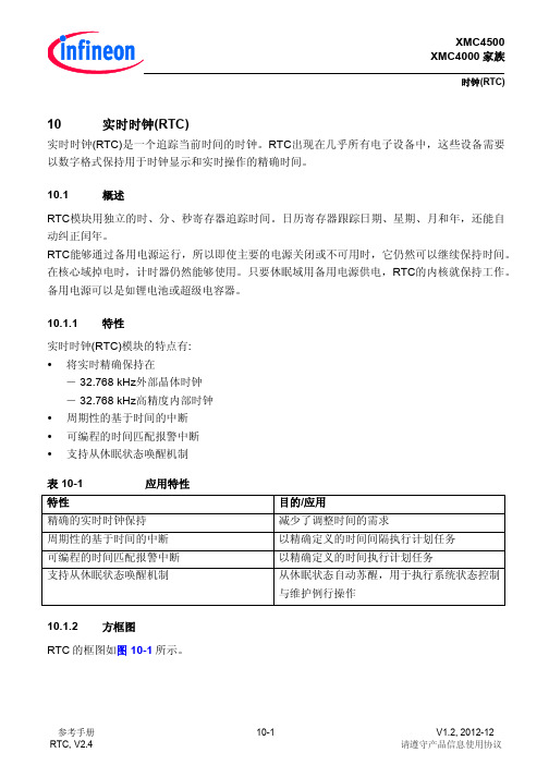
RTC 生成唤醒触发的条件: 周期定时器事件 配置报警条件
ห้องสมุดไป่ตู้
定时器事件可以在休眠域中作为从休眠模式唤醒触发被处理,在休眠域的 HCU 模块(更多细节请 参考 SCU 章中对休眠控制的描述)。 10.5.1 周期性唤醒触发生成
只要定时器的非屏蔽字段得到更新,周期性的定时器唤醒触发就会被生成。周期性唤醒触发的 生成可以被 CTR 寄存器启用/禁止。 10.5.2 定时器警报唤醒触发生成
只要 TIM0 和 TIM1 的所有位段值与 ATIM0、ATIM1 寄存器对应的位字段值匹配,警报唤醒触 发就会被生成。定时器报警唤醒触发的生成可以被 CTR 寄存器启用/禁止。
参考手册 RTC, V2.4
10-4
V1.2, 2012-12 请遵守产品信息使用协议
XMC4500 XMC4000 家族
参考手册 RTC, V2.4
10-7
V1.2, 2012-12 请遵守产品信息使用协议
XMC4500 XMC4000 家族
时钟(RTC)
10.9
寄存器
寄存器概述 绝对的寄存器地址通过下式算出: 模块基址+偏移地址 表 10-2 模块 RTC 表 10-3 缩写 寄存器地址空间 基址 5000 4A00H 寄存器概述 寄存器全称 偏移地址 访问方式 读 RTC 核心寄存器 ID CTR RAWSTAT STSSR MSKSR CLRSR ATIM0 ATIM1 TIM0 TIM1 10.9.1 ID RTC 模块中的只读 ID 寄存器包含唯一的 RTC 模块身份代码。 ID 寄存器 控制寄存器 原始服务请求寄存器 状态服务请求寄存器 屏蔽服务请求寄存器 清除服务请求寄存器 报警定时寄存器 0 报警定时寄存器 1 定时寄存器 0 定时寄存器 1 寄存器描述 0000H 0004H 0008H 000CH 0010H 0014H 0018H 001CH 0020H 0024H U,PV U,PV U,PV U,PV U,PV BE U,PV U,PV U,PV U,PV BE PV BE BE PV PV PV PV PV PV 10-8 页 10-9 页 10-11 页 10-12 页 10-13 页 10-14 页 10-15 页 10-16 页 10-17 页 10-19 页 写 描述 结束地址 5000 4BFFH 注释 通过镜像寄存器访问
安装维护手册

项目名称技术文档
安装维护手册
目录
1 概述
1.1 编写目的
[可照抄下列语句,也可适当修改。
]
本文档的编写目的在于为XXXX(软件名称)软件系统的用户方系统管理员和操作员提供一些必要的信息,以便用户可独立完成系统的安装和普通异常情况下的维护工作,达到使系统能够正常运行的目的。
1.2 参考资料
1.3 术语和缩写词
2 支持材料
详细列出安装实施过程中需要的支持性物质(包括磁带、磁盘、光盘等)和文档性资料。
3 安装
3.1 操作系统、支持软件和硬件环境的安装和配置
给出操作系统、支持软件和硬件环境的安装和配置的详细步骤及配置参数,包括通电、开机、关机、断电等细节和安装过程中的交互信息及回答内容。
最好配以图片。
3.2 应用软件系统的安装和初始化
给出软件系统的安装和初始化的详细步骤及配置参数,包括安装过程中的交互信息及回答内容。
最好配以图片。
4 维护
4.1 操作系统、支持软件和硬件环境维护
建议进行的日常或阶段性维护,以及可能的故障维护。
列出建议进行的日常或阶段性维护工作,处理流程和处理方法。
列出可能出现的故障及引起故障的可能原因、检查核实方法和处理方法。
并著名各种无法分析或无法解决的故障发生时的相应联系单位及个人,包括联系方式。
4.2 应用系统的维护
应用系统日常维护和故障维护。
列出应用系统需要进行的各种日常维护工作,处理流程和处理方法。
列出可能出现的故障及引起故障的可能原因、检查核实方法和处理方法。
并著名其它故障发生时的联系人及电话。
审核(项目经理):
年月日。
一款用于维护和检查设备的服务手册说明书

Connect inlet to port “B” for normally open valve. Port “A” is exhaust.Plug exhaust port for 2-way operation.Port Identifications / ConnectionsService ProceduresT o disassemble unit, use the following procedure:T o detach the hand toggle, cam head, or button actuator assembly from the valve body assembly, remove the 4 pan head screws (using a Philips screwdriver). T o remove the stem, stem guide, and seals from the body, unscrew the end plug using a 3/8" Allen wrench. Then gently press on the “pin” side of the stem until it slides out of the body. The stem guide may be removed by pulling axially on the radial holes drilled in the stem guide. Be careful not to scratch the sealing surfaces or cut the seals.Thoroughly clean the valve body bore and stem guide, and inspect for possible nicks, scratches and material imperfections. Lightly lubricate the stem seals. (Use a non-detergent hydro-carbon based oil or grease.) Replace any o-rings or other seals if they are damaged.The Assembly procedure is the reverse of the above. Tighten the end plug to 60 in-lbs and apply 15-18 in-lbs of torque to the pan head mounting screws.If you have questions concerning how to service this unit, contact your local authorized dealer or your customer service representative.Application LimitsThese products are intended for use in general purpose compressed air systems only.Operating Pressure Range:psig Bar kPa Minimum 000Maximum150101000Operating Temperature Range:0°F to 160°F(-18°C to 71°C)Installation & Operating InstructionsValve should be installed with reasonable accessibility for service whenever possible - repair service kits are available. Keep pipe or tubing lengths to a minimum with inside clean and free of dirt and chips. Pipe joint compound should be used sparingly and applied only to the male pipe - never into the female port. Do not use PTFE tape to seal pipe joints - pieces have a tendency to break off and lodge inside the unit, possibly causing malfunction.Filtered and lubricated air is necessary for maximum valve life and minimum maintenance.Factory Pre-Lubrication - All valves are pre-lubricated at assembly with a petroleum based grease.Valve OperationThese valves will operate mounted in any position; they are also suitable for vacuum service.Series C & CW (wall mounting) valves can be operated either Normally Closed to pressure or Normally Open to pressure.Connect inlet to port “A” for normally closed valve. Port “B” is exhaust.Normally ClosedNormally OpenInstallation & Service Instructions V-222DC2, C3, C3M1A, C4, C5, C9, C13, C92, C94,CW2, CW3, CW3M1A, CW4, CW5, CW9,CW13, CW92, & CW94 Series Valves ISSUED: September, 2000Supersedes: February, 1994ECN# P27805Pneumatic Division North America Richland, Michigan 49083!!WARNINGTo avoid unpredictable system behavior that can cause personal injury and property damage:•Disconnect electrical supply (when necessary) before installation,servicing, or conversion.•Disconnect air supply and depressurize all air lines connected to this product before installation, servicing, or conversion.•Operate within the manufacturer’s specified pressure, temperature,and other conditions listed in these instructions.•Medium must be moisture-free if ambient temperature is below freezing.•Service according to procedures listed in these instructions.•Installation, service, and conversion of these products must be performed by knowledgeable personnel who understand how pneumatic products are to be applied.•After installation, servicing, or conversion, air and electrical supplies (when necessary) should be connected and the product tested for proper function and leakage. If audible leakage is present,or the product does not operate properly, do not put into use.•Warnings and specifications on the product should not be covered by paint, etc. If masking is not possible, contact your local representative for replacement labels.WARNINGFAILURE OR IMPROPER SELECTION OR IMPROPER USE OF THE PRODUCTS AND/OR SYSTEMS DESCRIBED HEREIN OR RELATED ITEMS CAN CAUSE DEATH, PERSONAL INJURY AND PROPERTY DAMAGE.This document and other information from Parker Hannifin Corporation,its subsidiaries and authorized distributors provide product and/or system options for further investigation by users having technical expertise. It is important that you analyze all aspects of your application,including consequences of any failure and review the information concerning the product or systems in the current product catalog. Due to the variety of operating conditions and applications for these products or systems, the user, through its own analysis and testing, is solely responsible for making the final selection of the products and systems and assuring that all performance, safety and warning requirements of the application are met.The products described herein, including without limitation, product features, specifications, designs, availability and pricing, are subject to change by Parker Hannifin Corporation and its subsidiaries at any time without notice.EXTRA COPIES OF THESE INSTRUCTIONS ARE AVAILABLE FOR INCLUSION IN EQUIPMENT / MAINTENANCE MANUALS THAT UTILIZE THESE PRODUCTS. CONTACT YOUR LOCAL REPRESENTATIVE.V-222D Maintenance & Trouble Shooting Hints:Air Leakage Through Exhaust Ports:1.Check for internal leakage in cylinder being operated byvalve.2.Check center stem seal for nicks, cracks, peeling and/ordelamination.3.Check for missing, damaged, swollen, or incorrectlyassembled o-rings and gaskets.4.Check stem guide and body bore for nicks, scratches, anddirt particles.Replace worn or damaged parts. Re-assemble and re-test unit.Service Kit and Parts AvailableValve Body Service Kit:(consists of items # 3, 4, 5, 7, 8, & 9)PL502600Valve Body Assemblies:C25 (1/4" NPTF Ports)PL2479C37 (3/8" NPTF Ports)PL2480CW25 (1/4" NPTF Ports)PL2481CW37 (3/8" NPTF Ports)PL2482Hand Toggle Actuator AssemblyNon-Locking PL3355LockingCam Head AssemblyBall (C & CW2)PL2209Roller (Overriding C & CW9)PL2210Roller (C & CW13)PL2422Heavy Duty Roller (Uni-Directional C & CW92)PL4030D Heavy Duty Roller (Bi-Directional C & CW94)PL4009D Palm Button Actuator Assembly1 5/16" Dia. Button PL22082 1/2" Dia. ButtonPL4005Part Identification ListItem #Description1Valve Body Assembly2Valve Body3Stem Retainer Snap Ring 4Stem O-ring 5Stem6Stem Guide7Stem Guide Gasket 8Stem Guide O-ring 9Stem Return Spring 10End PlugHeavy Duty Roller Cam Head Bi-Directional: C94 &CW94Palm Button ActuatorC3 & CW3Ball Cam Head C2 & CW2Hand Toggle Actuater Non-locking: C4 & CW4Locking: C5 & CW5Heavy Duty Overriding Roller Cam HeadUni-Directional: C92 & CW92。
PCS1800控制系统用户手册V1.2-3安装维护手册

浙江正泰中自控制工程有限公司版权所有
1
PCS1800 分布式控制系统用户手册-安装维护手册
前言
首先感谢您选用 PCS1800 分布式控制系统。
本手册详细介绍 PCS1800 分布式控制系统的安装维护过程,具体包括安装顺序、模块和组件 介绍、系统配置规则、系统安装步骤、系统接线方法、系统调试方法、系统维护和诊断要点等内 容。
4.1.组件尺寸 ........................................................... 5 4.2.机架 ............................................................... 8
4.2.1.主机架和扩展机架 ................................................... 8 4.2.2.机架安装方式 ....................................................... 9 4.2.3.机架间距要求 ....................................................... 9 4.2.4.机架上模块排列 ..................................................... 9 4.3.机柜 .............................................................. 11 4.3.1.机柜选择 .......................................................... 11 4.3.2.机柜布局要求 ...................................................... 13 4.4.接地规范 .......................................................... 13
安装和清洁维护操作手册说明书

WARNINGREAD AND SAVE THESE INSTRUCTIONS Installer: Leave this manual with the homeowner.CAUTIONCLEANING & MAINTENANCEOPERATIONFor quiet and efficient operation, long life, and attractive appearance - lower or remove grille and vacuum interior of unit with the dusting brush attachment.The motor is permanently lubricated and never needs oiling. If the motor bearings are making excessive or unusual noises, replace the motor with the exact service motor. The impeller should also be replaced.SE80TL SE110L SE150La). Use this unit only in the manner intended by the manufacturer. If you have questions, contact the manufacturer.b). Before servicing or cleaning unit, switch power off at service panel and lock the service disconnecting means to prevent power from being switching on accidentally. When the service disconnecting means cannot be locked, securely fasten a prominent warning device, such as a tag, to the service panel.c). Installation work and electrical wiring must be done by a qualified person(s) in accordance with all applicable codes and standards, including fire-rated construction codes and standards.d). Sufficient air is needed for proper combustion and exhausting of gases through the flue (chimney) of fuel burning equip- ment to prevent backdrafting. Follow the heating equipment manufacturer’s guideline and safety standards such as those published by the National Fire Protection Association (NFPA), and the American Society for Heating, Refrigeration and Air Conditioning Engineers (ASHRAE), and the local code authorities.e). When cutting or drilling into wall or ceiling, do not damage electrical wiring and other hidden utilities. f ). Ducted fans must always be vented to the outdoors.g). Acceptable for use over a tub or shower when connected to a GFCI (Ground Fault Circuit Interrupter) - protected branch circuit (ceiling installation only). h).This unit must be grounded. i). Not for Use in Kitchens.j). To reduce risk of fire and to properly exhaust air, be sure to duct air outside – Do not vent exhaust air into spaces within walls or ceilings or into attics, crawl spaces, or garages.k).WARNING: To Reduce The Risk Of Fire Or Electric Shock, Do Not Use This Fan With Any Solid-State Speed Control Device.l). The fan must not be installed in a ceiling thermally insulated to a value greater R40.1.For general ventilating use only. Do not use to exhaust hazardous or explosive materials and vapors.2.This product is designed for installation in ceilings up to a 12/12 pitch (45 degree angle). Duct connector must point up.DO NOT MOUNT THIS PRODUCT IN A WALL.3.To avoid motor bearing damage and noisy and/or unbalanced impellers, keep drywall spray, construction dust, etc. off power unit.4.Please read specification label on product for further information and requirements.*The manual in electronic format can be download in our company web, or obtained from our dealer.WARNING -TO REDUCE THE RISK OF FIRE, ELECTRIC SHOCK, OR INJURY TO PERSONS, OBSERVE THE FOLLOWING:The fan, light, and night light can be operated separately. Use a 3-function wall control. See “Connect Wiring” for details.Hold the housing so that it is in contact with the bottom of the joist. Attach the housing with four (4) screws to the joist through the holes in each mounting flange.1. MOUNT HOUSING TO JOIST OR I-JOIST.HANGER BAR2. MOUNT WITH HANGER BARS2a. Sliding hanger bars have been provided, which allow the housing to be positioned accurately anywhere between the framing. The bars span up to 24 in. and can be used on all types offraming: I-joist, standard joist, and truss construction. Slide hanger bars onto housing and adjust as needed to fit between framing.2b. Extend the hanger bars to the width of the framing. Position the ventilator with the hanger bar tabs wrapped around the bottom edge of the framing, holding the ventilator in place.Secure hanger bars to framing using one screw on each end of hanger bar.Select a proper hole and secure the hanger bars together using flange screws.3. ATTACH DAMPER/DUCT CONNECTORSnap the damper/duct connector onto the fan housing. The connector must be flush with the top of the housing, and the damper flap should fall closed.Insulated flexible duct is recommended for the quietest possible installation. If rigid duct is used, a short (1-3 feet) section of insulated flexible duct will ensure quiet operation.TYPES OF TYPICAL INSTALLATIONS1. Do not use in a cooking area.2. Two ways to connect ductwork to a factory-shipped unit.ASSEMBLY INSTRUCTIONS1. Housing mounted to I-joists (Start at “ASSEMBLY INSTRUCTIONS 1”)2. Housing mounted to joists (Start at “ASSEMBLY INSTRUCTIONS 1” )3. Housing mounted to truss (Start at step “ASSEMBLY INSTRUCTIONS 2”)PLAN THE INSTALLATION4. INSTALL ROUND DUCTWORKConnect the round ductwork (not included) to the damper/duct connector, and run the ductwork to a roof or wall cap (not included). Using tape (not included), secure all the ductwork connections so that they are air tight.ASSEMBLY INSTRUCTIONSCONNECT ELECTRICAL WIRINGINSTALL GRILLERun 120 V AC house wiring to the location of the fan. Use only UL-approved connectors (not included) to attach the house wiring to the wiring plate. Refer to the wiring diagram, and connect the wires as shown.The ducting from this fan to the outside of building has a strong effect on the air flow, noise and energy use of the fan. Use the shortest, straightest duct routing possible for best performance, and avoid installing the fan with smaller ducts than recommended. Insulation around the ducts can reduce energy loss and inhibit mold growth. Fans installed with existing ducts may not achieve their rated air flow.Insert the light plug from the grille assembly into the wire panel.Pinch the grille springs on the sides of the grille, and position the grille into the housing with the grille springs in the appropriate slots. Push the grille assembly towards the ceiling to secure.Remove the lensCarefully pry out the light lens by inserting a small,flathead screwdriver between the grille and lens.Install the light bulbsInstall a 26W max. fluorescent bulb and a 4W incandescent night light bulb. Replace the lens.This warranty covers all defects in workmanship or materials for:The mechanical and electrical parts contained in this product, for a period of 12 months, from the date of purchase. You must keep and be able to provide your original sales receipt as proof of the date of purchase. This warranty is covered the original retail purchaser of this product. The manufacturer will repair or replace, in your home, any mechanical or electrical part which proves defective in normal household use for a period of 12 months.THIS WARRANTY DOES NOT COVER:• Damages from improper installation • Damages from shipping• Damages from misuse, abuse, accident, alteration, lack of proper care and maintenance • Damages from service by persons other than an authorized dealer or service center.• Labor, service, transportation and shipping charges for the removal of defective parts and for installation of a replacement part, beyond the initial 12-month period.This warranty does not extend to fluorescent lamp starters and tubes.THIS LIMITED WARRANTY IS GIVEN IN LIEU OF ALL OTHER WARRANTIES, EXPRESSED OR IMPLIED,INCLUDING THE WARRANTIES OF MERCHANTABILITY AND FITNESS FOR A PARTICULAR PURPOSE.The remedy provided in this warranty is exclusive and is granted in lieu of all other remedies. This warranty does not cover incidental or consequential damages. Some states do not allow the exclusion of incidental or consequential damages, so this limitation may not apply to you. Some states do not allow limitations on how long an implied warranty lasts, so this limitation may not apply to you. This warranty gives you specific legal rights, and you may also have other rights, which vary from state to state.WARRANTYSERVICE PARTS45d e a3bc 68799PARTPART NAMEQty.1234567891011a b c d eHousingDamper / Duct Connector Wiring plate Screw Blower WheelWire Panel / Harness Assembly Motor1211111141144141Isolator Motor Plate Washer Nut, Hex Lock Grille Assembly (includes part 2&11)Grille Spring Hanger Bar KitScrew* Blower Assembly includes part 5, 4, d, 3, c, b, a. Replacement installation:Remove the screw (part c), then take out the motor plate (part 3) from the housing (part 8) by pushing down the rib in the plate while pulling out on the side of the housing. Replace the broken parts.WARNING: Ensure that the fan is switched off from the supply mains before replacing.Lens。
维护手册

维护手册四车定位系统概述焦化厂的推焦车、拦焦车、熄焦车和装煤车相互间的通信、地址炉号对位、推焦动作联锁、装煤动作联锁以及最终达到计算机集中联控等一系列自动化技术问题的解决,对焦化厂的安全生产和提高生产管理水平,提高产品质量和经济效益有着十分重要的意义。
目前,我国大多数焦化企业在焦炉四大车的运行中还是采用落后的人工操作方式——即人眼定位,人工通信(吹哨或对讲机通信)。
这种方式存在很多安全隐患:在大雨、大雾、大风等恶劣气候条件下,人眼很难准确定位,在焦化现场,存在较强的电气干扰,对讲机很难保证清晰的话音,这样定位不准确,就会使推焦杆在推焦过程中刮碰炉壁,从而降低焦炉的使用寿命;若机车未准确对位,就开始推焦,就会红焦落地,造成重大生产事故。
为了解决焦炉四大车的定位和通信问题,不少企业投入了大量的人力、物力、财力,在四车联锁方面进行了大量的研究和试验,并取得了阶段性的成果。
当前国内外焦炉四大车定位主要采用旋转编码器位置检测技术、编码电缆位置检测技术、定位片电磁编码位置检测技术、条形码位置检测技术等,在众多的定位技术中,编码电缆位置检测技术最为成熟。
该技术是通过铺设在移动机车轨道旁的编码电缆来测量机车的位置的。
在武钢、太钢、邢钢、临钢等焦化厂的应用实践表明,采用该技术定位精确度高达10mm,完全可以满足在炼焦生产过程中对移动机车的定位要求,而且设备运行稳定。
四大车的通信方式大多采用无线或感应无线的通信方式。
将感应无线技术应用在移动机车的定位上是相当成功的,但将其应用在数据通信上,其缺点是明显的。
首先其工作频率较低(100KHz左右),容易受到电气干扰,在邢钢、临钢的应用实践表明,这个频段容易受到变频器的谐波干扰;其次其通信环路过长,设备复杂,稳定性较差,成本高。
近年来,无线电通信技术飞速发展,已由过去的模拟方式发展到现在的数字方式,其特点是硬件设备简单、通信速度快、通信误码低。
本公司经过多年的研究和探索,已掌握了编码电缆的编制方法和生产技术,掌握了编码电缆的定位技术。
视聆通安装维护手册

视聆通节点后台管理系统安装维护手册广东省邮电科学技术研究院1999.7目录1.使用说明 (4)1.1字体 (4)1.2部分变参字符串 (4)1.3部分操作名称与缩写 (4)2.视聆通节点后台管理系统安装指南 (5)2.1系统安装条件 (5)2.2视聆通节点后台管理系统的安装 (5)2.2.1后台管理系统文件的安装(安装新系统) (5)2.2.2后台管理系统文件的安装(升级系统) (5)2.2.3后台管理系统文件系统简介 (6)2.2.4在Javascript Application Manager中安装后台管理系统 (6)2.3安装用户修改密码程序 (7)2.4在华为取主叫PC上安装PC-NFS(如果有CISCO2511做接入服务器) (8)2.4.1安装PC-NFS (8)2.4.2PC-NFS配置: (8)2.5安装P OWER B UILDER D EPLOYMENT KIT (9)2.5.1客户端的Sybase 软件的安装: (9)2.5.2PowerBuilder Deployment kit的安装: (9)2.5.3拷贝报表打印程序 (9)2.6文件配置: (10)2.6.1SQLEDIT里的DB Server配置: (10)2.6.2配置路径: (10)2.6.3浏览器配置: (10)2.6.4注意事项: (11)3.视聆通节点后台管理系统维护指南 (12)3.1数据库系统维护与管理 (12)3.1.1检查数据库服务器是否运行 (12)3.1.2启动数据库服务器 (12)3.1.3数据库操作常用命令 (13)3.1.4数据备份与恢复 (13)3.1.5视聆通数据库主要库表的结构 (14)3.1.6备份数据文件 (16)3.2N ETSCAPE E NTERPRISE S ERVER维护与管理 (17)3.2.1查看Netscape Enterprise Server是否运行 (17)3.2.2启动Netscape Enterprise Server (18)3.2.3Netscape Enterprise Server的管理 (18)3.3认证系统 (18)3.3.1认证协议 (18)3.3.2与数据库关系 (18)3.3.3A、B、D类用户的IP地址分配 (19)3.3.4主被叫电话号码的获取 (19)3.3.5用户漫游认证 (19)3.3.6用户上网唯一性实现方法 (20)3.3.7唯一性出错处理 (20)3.3.8Radius认证服务器的运行保护 (20)3.3.9与认证相关的主要文件 (20)3.3.10认证系统升级的安装过程 (23)3.3.11认证系统常见问题 (26)3.4主机系统用户管理 (28)3.4.1主机系统用户 (28)3.4.2主要文件说明 (28)3.4.3出错信息说明 (29)4.后台系统常见错误 (30)4.1系统操作非常缓慢 (30)4.2卡号管理 (30)4.3用户管理 (31)4.4其他常见错误和注意事项 (33)5.视聆通后台升级安装及维护 (33)5.1后台软件的升级 (34)5.2数据库的升级 (34)5.2.1数据库gnet的部分表的的调整和增加 (34)5.2.2给部分表加外部键(foreign key) (36)5.2.3整理数据 (38)5.2.4编写存储过程 (38)5.2.5编写上下传程序 (39)5.2.6数据库性能调整 (39)1.使用说明在本手册中,将使用不同字体及字符串代表不同的意思。
TW2维护手册

TW-2型驼峰自动化系统维护手册北京全路通信信号研究设计院第1 页共56 页TW-2型驼峰自动化系统维护手册北京全路通信信号研究设计院目录1.综述 (4)2.系统组成与结构 (5)2.1现场设备 (5)2.1.1道岔转辙设备 (5)2.1.2轨道电路 (5)2.1.3色灯信号机 (5)2.1.4车辆减速器 (5)2.1.5雷达 (5)2.1.6轮轴探测器(踏板) (5)2.1.7测长轨道电路 (5)2.1.8测重 (6)2.2驼峰控制台室内设备 (6)2.2.1调车区长站 (6)2.2.2调车长站 (6)2.2.3调速站 (6)2.2.4手动控制台(盘) (7)2.3机房及机械室设备 (7)2.3.1控制机柜 (7)2.3.2维护站 (7)2.3.3报警打印机 (8)2.3.4交流净化电源或25周变频电源 (8)2.3.5UPS不间断电源 (8)2.3.6接口继电器组合柜(架) (8)2.3.7分线柜(盘) (8)2.4系统电源连接及通道连接示意图(典型情况) (9)3.维修人员需掌握的内容 (12)4.信息窗的使用 (13)4.1信息窗的显示 (13)4.2信息窗的操作 (13)4.2.1上层操作命令 (14)4.2.2上层调试命令 (14)4.2.3报警与记录信息检索 (15)4.2.4勾车统计报告 (15)4.2.5仿真终端 (15)4.2.6系统状态监测 (15)4.2.7道岔转动次数统计 (16)4.2.8调制解调器操作 (16)4.2.9维护信息 (17)4.2.10退出 (17)4.3报警与记录信息检索窗的使用 (17)4.3.1树型窗 (17)4.3.2选择窗: (17)4.3.3参数设置窗: (18)4.3.4报警信息窗 (18)4.4报警信息窗中的菜单操作 (19)4.4.1新的查询 (19)4.4.2退出查询 (19)4.4.3打印结果 (20)4.4.4信息保存 (20)第2 页共56 页TW-2型驼峰自动化系统维护手册北京全路通信信号研究设计院4.4.5概要记录统计 (20)4.4.6查询暂停与查询继续 (20)4.4.7剔除该项与恢复剔除 (20)4.5报警与记录的检索分类及说明 (20)4.6统计报告窗操作说明 (32)4.6.1调车作业计划表: (33)4.6.2计划执行概要表: (33)4.6.3计划速度控制表 (34)4.6.4车站运营状态表 (35)4.6.5勾车详细信息 (40)4.6.6减速器控制误差统计 (41)5.上层机维护诊断命令 (43)6.下层模块的维护诊断操作 (44)6.1各微机板监控命令 (44)6.2ZB、LB板 (44)6.3CB板 (44)6.4JB板 (46)7.常见问题的分析 (49)7.1怀疑某开关量输入不正确 (49)7.2怀疑某静态输出没有 (49)7.3怀疑某动态输出没有 (49)7.4减速器出口速度偏高 (49)7.5减速器出口速度偏低 (50)7.6勾车错道 (50)7.7溜放中有不正确的报警 (50)7.8测长不准确 (51)7.9计轴不准确 (51)7.10双机不同步 (51)7.11全场输入均不正确 (51)7.12全场雷达均报故障 (51)7.13全场测长均为零,或均报故障 (51)8.有关执表的内容 (52)8.1测长轨道电路 (52)8.2交流净化电源 (52)8.3双机同步 (52)8.4主备机轮换使用 (52)8.5工作站、键盘、鼠标的清理 (52)8.6通过查询统计检查室外设备状态 (52)8.7UPS电源检查 (52)8.8无源踏板检查 (53)8.9测重检查 (53)8.10通道电源检查 (53)8.11机柜内部检查 (53)8.12接地电阻检查 (53)9.维护注意事项 (54)第3 页共56 页TW-2型驼峰自动化系统维护手册北京全路通信信号研究设计院1.综述TW-2系列组态式驼峰自动控制系统是在我单位已有的各个子系统(包括:TWJ-2溜放进路控制、TWZ-1自动集中、TWK-1溜放速度控制、TWGC-1工频测长)基础之上,统一构造,统一管理,统一操作,统一监控,其控制模块(包括硬、软件)可按需配置和组合,适合大中小不同站场规模,适合于不同功能选择与取舍的场合。
VQC2000(V100)-TFP35_ETC安装和维护手册说明书

Installation & Maintenance Manual Solenoid valve for manifold pilot control:VQC2101NY-5-X10(Basic and well-tried safety principles inaccordance to ISO 13849)The intended use of the valve is to control the external pilot air of other valves on the same valve manifold.This product is validated according to ISO 13849 basic and well-tried safety principles. Refer to Doc. Nr. VQC2000V-SMP0002.This manual contains essential information for the protection of users and others from possible injury and/or equipment damage.•Read this manual before using the product, to ensure correct handling, and read the manuals of related apparatus before use.•Keep this manual in a safe place for future reference.•These instructions indicate the level of potential hazard by label of “DANGER”, “WARNING” or “CAUTION”, followed by important safety information which must be carefully followed.•To ensure safety of personnel and equipment the instructions in this manual and the product catalogue must be observed, along with other relevant safety practices.Take care about the compliance with the relevant safety laws and standards.CAUTION Indicates a hazard with a low level of risk,which if not avoided, could result in minor ormoderate injury.WARNING Indicates a hazard with a medium level ofrisk, which if not avoided, could result indeath or serious injury.DANGER Indicates a hazard with a high level of risk,which if not avoided, will result in death orinjury.WARNING•Thecompatibility of pneumatic equipment is theresponsibilityof theperson who designs the pneumatic system or decides its specifications.Since the products specified here can be used in various operatingconditions, their compatibility with the specific pneumatic system mustbe based on specifications or after analysis and/or tests to meetspecific requirements.•Only trained personnel should operate pneumatically operatedmachinery and equipment.Compressed air can be dangerous if an operator is unfamiliar with it.Assembly, handling or repair of pneumatic systems should beperformed by trained and experienced personnel.•Do not service machinery/equipment or attempt to removecomponents until safety is confirmed.1) Inspection and maintenance of machinery/equipment should only beperformed after confirmation of safe locked-out control positions.2) When equipment is to be removed, confirm the safety process asmentioned above. Switch off air and electrical supplies and exhaust allresidual compressed air in the system.3) Before machinery/equipment is re-started, ensure all safetymeasures to prevent sudden movement of cylinders etc. (Supply airinto the system gradually to create back pressure, i.e. incorporate asoft-start valve).•Do not use this product outside of the specifications. Contact SMCif it is to be used in any of the following conditions:1) Conditions and environments beyond the given specifications, or ifthe product is to be used outdoors.2) Installations in conjunction with atomic energy, railway, air navigation,vehicles, medical equipment, food and beverage, recreation equipment,emergency stop circuits, press applications, or safety equipment.3) An application which has the possibility of having negative effects onpeople, property, or animals, requiring special safety analysis.•Effect of back pressure when using a manifoldThis valve is designed to be used on a manifold. This valve mayexperience back pressure due to pressure in the manifold exhaust ports.Back pressure check valves can be used to prevent back pressureaffecting the outlet ports of this valve.•VentilationProvide ventilation when using a valve in a confined area, such as in aclosed control panel. For example, install a ventilation opening, etc. inorder to prevent pressure from increasing inside of the confined areaand to release the heat generated by the valve.•Operation in a low temperature conditionIt is possible to operate a valve in extreme temperature, as low as–10 C. Take appropriate measures to avoid freezing of drainage,moisture etc. in low temperature.•Do not disassemble the product or make any modificationsCAUTION•Ensure that the air supply system is filtered to 5 µm.2 Specifications2.1 General specificationsValve Type Special 5-Port Solenoid Valve Note 1)Valve Configuration Rubber seal (Pilot valve V100)De-energized actuation Air / spring returnFluid AirMax. operating pressure 0.7 MPaMin. operating pressure 0.25 MPaProof pressure 1.05 MPaResponse time 31 ms or less Note 2)Minimum frequency 1 cycle / 30 daysMass 105 gAmbient temperature -10 to +50°C (No freezing)LubricationNot requiredManual override Push typeImpact resistance/ Vibration resistance 150 / 30 m/s2Note 3)Mounting orientation universalEnclosure IP67ValvespecificationsService life B10Refer to VQC2000V-SMP0002Rated coil voltage 24 VDCAllowable voltage fluctuation ±10 % of rated voltage Note 4)Coil insulation type Class B or equivalentElect.Power consumption (Current) 24 VDC 0.4 W DC (17 mA)Table 12.2 Flow-rateFlow-rate Characteristics1 -> 4,2 (P > A,B) 4,2 -> 5,3 (A,B > R1,R2)ModelC[dm3/(s.bar)] b Cv C[dm3/(s.bar)] b CvVQC2101NY-5-X10 2.2 0.28 0.55 3.2 0.30 0.80Table 2Note 1)When the Air Supply is cut (port 1 (P)) the main valve returns to the originalposition.Note 2)Values represented in this column are based on JIS 8375-1981 (operatingwith clean air and a supply pressure of 0,5 MPa equipped with light/surgevoltage suppressor. Values vary depending on the pressure as well as the airquality.) Tested with ports size C8 and without back pressure check valvesNote 3)Impact resistance: No malfunction occurred when it was tested with a droptester in the axial direction and at right angles to the main valve & armature;in both energized & de-energised states and for every time in each condition(Values at the initial period.)Vibration resistance: No malfunction occurred in a one-sweep test between45 and 2000 Hz. Tests are performed at both energized and de-energizedstates in the axial direction and at right angles to the main valve & armature.Note 4) If power supply is under -10% of standard power supply 24 V DC thevalve may switch to the OFF position. The valve may switch to thede-energized state.2.3 SymbolFigure 32.4 Light/Surge Voltage SuppressorFigure 4Valve is only available as negative COM Type (PNP).3 InstallationWARNING3.1 Environment1. Do not use in an environment where the product is directly exposed tocorrosive gases, chemicals, salt water, water or steam.2. Products with IP67 enclosures (based on IEC60529) are protectedagainst dust and water, however, these products cannot be used in water.3. Incorrect mounting of the product violates the IP67 rating. Be sure to readthe precautions of mounting for each product.4. Do not use in an explosive atmosphere.5.The product should not be exposed to prolonged sunlight. Use a protectivecover.6. Do not mount the product in a location where it is subject to strongvibrations and/or shock. Check the product specifications.7. Do not mount the product in a location exposed to radiant heat.3.2 Piping1. Preparation before pipingBefore piping is connected, it should be thoroughly blown out with air(flushing) or washed to remove chips, cutting oil and other debris frominside the pipe.Install piping so that it does not apply pulling, pressing, bending or otherforces the valve body.2. Holding of pressureRubber sealed spool valves may have a slight leakage. This has to betaken into account for applications, in which the loss of pressure leads toa hazardous movement.3. Maintenance space.The installation should have sufficient space for maintenance activities(removal of valve, etc.).4. Release of residual pressure.Provide a residual pressure release function for maintenance activities(removal of valve, etc.)CAUTION3 3.3 Lubrication•SMC products have been lubricated for life at manufacture, and do notrequire lubrication in service.•If a lubricant is used in the system, use turbine oil Class 1 (no additive),ISO VG32. Once lubricant is used in the system, lubrication must becontinued because the original lubricant applied during manufacturingwill be washed away.WARNING3.4 Mounting1. Stop operation if air leakage increases and the equipment do notoperate properly.Check mounting conditions after air and power supplies are connected.Initial function and leakage tests should be performed after installation.2. Instruction manual (this document)Install only after reading and understanding the safety instructions. Keepon file so that it can be referred to when necessary.3. CoatingWarnings or specifications indicated on the product should not be erased,removed, or covered up.CAUTION3.5 Wiring1. Applied voltage.When electric power is connected to the solenoid valve, be careful toapply the proper voltage. Improper voltage may cause malfunction or coildamage.2. Confirm the connections.After completing the wiring, confirm that the connections are madecorrectly.4 Settings4.1 Manual overrideWARNINGSince connected equipment will operate when the manual override isactivated, confirm that conditions are safe prior to activation. Thenon-locking push type (tool required) is standard.Non-locking push type (Tool required)Figure 5The manual override will actuating the pilot valve and the pilot valvepressure will actuating the main valve movement.4.2 Solenoid Valve Removal and Mounting (VQC2000)Figure 6Clamp AClamp BClamp Screw ORIGINAL INSTRUCTIONS4.2.1 Removal steps1. Loosen the clamp screws until they turn freely. (The screws do not come out.)2. Remove the solenoid valve from clamp B by lifting the coil side of the valve while pushing on the screw top. If pushing down on the screw is difficult, you can alternately press down on the valve gently in the area near the manual override.4.2.2 Mounting steps1.Push the clamp screws. Clamp A opens. Now insert the end plate hook of the valve into clamp B at an angle.2. Push the valve down into place. (When you release the screws, the valve will be locked into clamp A.)3. Tighten the clamp screws with a tightening torque of 0.5 to 0.7 N ・mCAUTIONDust on the sealing surface of the gasket or solenoid valve can cause air leakage.Take care that the pilot pressure is able to exhaust. Do not block the Exhaust Ports.Order Number VQC2101NY-5-X10Special Pilot valve Cover (Color: Red)( Dimensions are in Millimeter )WARNING1. Perform maintenance procedures shown in this instruction manual. If handled improperly malfunction or damage of machinery/equipment may occur.2. Removing the productTo avoid the risk of being burned, ensure that the valve has had sufficient time to cool before performing work.1. Shut off the fluid supply and release the fluid pressure in the system.2. In the case of air pilot or air-operated type, shut off the supply air source and discharge the compressed air inside the pilot piping.3. Shut off the power supply.4. Remove the product.3. Low frequency operation.Valves should be operated at least once every 30 days to prevent malfunction. (Use caution regarding the air supply).For optimum usage, conduct regular inspections every 6 months.4. Manual overrideWhen the manual override is operated, connected equipment will be actuated.5. Do not disassemble the product.CAUTION1. Filters and strainers1. Be careful regarding clogging of filters and strainers.2. Replace filter elements after one year of use, or earlier if the pressuredrop reaches 0.1 MPa.3. Clean strainers when the pressure drop reaches 0.1 MPa.2. Drain flushingRemove drainage from air filters regularly. (Refer to the specifications.)5.1 Replacing One-touch fittingsCAUTIONCylinder port fittingsare available with cassette type manifolds and are easily replaced. Fittings are secured with a retaining clip that is inserted vertically from either the top or bottom of the manifold. After removing the valve, remove the clip with a flat head screwdriver to replace the fittings. To mount a fitting, insert the fitting assembly until it spots and reinsert the retaining clip to its designated position.Figure 78 Limitations of UseDANGERThis Special Valve is developed for use only on a Special Manifold block Assembly: VVQC2000-1A-#-C0-X10 # = S – single wiring # = D – double wiringUse on other manifold block assemblies is not allowed. This can cause damage or malfunction.Any use in an EN ISO 13849 system must be within the specified limits and application condition. The user is responsible for the specification, design, implementation, validation and maintenance of the safety system (SRP/CS).WarningIf a safe output from a safety relay or PLC is used to operate this valve, ensure that any output test pulse duration is shorter than 1 ms to avoid the valve solenoid responding.6 ContactsAUSTRIA (43) 2262 62280-0 LATVIA(371) 781 77 00 BELGIUM (32) 3 355 1464 LITHUANIA(370) 5 264 8126 BULGARIA (359) 2 974 4492 NETHERLANDS (31) 20 531 8888 CZECH REP. (420) 541 424 611 NORWAY (47) 67 12 90 20 DENMARK (45) 7025 2900 POLAND (48) 22 211 9600 ESTONIA (372) 651 0370 PORTUGAL (351) 21 471 1880 FINLAND (358) 207 513513 ROMANIA (40) 21 320 5111 FRANCE (33) 1 6476 1000 SLOVAKIA (421) 2 444 56725 GERMANY (49) 6103 4020 SLOVENIA (386) 73 885 412 GREECE (30) 210 271 7265 SPAIN (34) 945 184 100 HUNGARY (36) 23 511 390 SWEDEN(46) 8 603 1200 IRELAND (353) 1 403 9000SWITZERLAND (41) 52 396 3131 ITALY(39) 02 92711UNITED KINGDOM(44) 1908 563888SMC Corporation www.smcworld,com (Global) (Europe) SMC Corporation, Akihabara UDX15F, 4-14-1, Sotokanda, Chiyoda-ku, Tokyo 101-0021 JAPANSpecifications are subject to change without prior notice from the manufacturer. The descriptions of products in this document may be used by other companies. © 2012 SMC Corporation All Rights Reserved.。
安装调试运行和维护保养手册

阅读索引READING INDEX1.操作者人身安全注意事项说明NOTICE ITEM OF OPERATERS PERSONALSAFETY--------------------------------------------------------------------------------------------2 2.参数页、结构原理ATTACHED PAGES、STRUCTURE AND PRINCIPLE ------33. 安装、试运行INSTALLATION AND TRYING RUN ------------------------------54. 运行注意事项NOTICE ITEM OF RUNNING ---------------------------------------75. 设备保养、维护MAINTENANCE OF EQUIPMENTS ----------------------------81.操作者人身安全类注意事项说明NOTICE ITEM OF OPERATERS PERSONALSAFETY设备内部的磁滚筒能产生非常强的磁场,因此所有接近此设备的工作人员必须知晓其潜在的危险性,切不可掉以轻心。
磁场主要集中在磁滚筒皮带表面,但磁滚筒四周仍会有部分弱磁场。
特此制订如下安全守则:1)磁场会使心脏起博器受到严重损坏。
带有心脏起搏器的人应在确知磁场对起搏器无影响的前提下才能接近设备。
如果情况不明,应在磁场完全消失后再接近设备。
2)请不要在磁场附近使用铁制工具或器件,特别是带尖角的器具,防止磁滚筒将其吸附,造成人身或物品损伤。
3)请不要携带磁存储传媒物如计算机磁盘、磁带及信用卡等接近设备,因为磁场会抹掉其上信息,使其无法使用。
4)请不要在磁场附近携带手表或配有电源的工具,磁场会对其磁化。
2、结构原理STRUCTURE AND PRINCIPLE2.1概述LCGX系列高频涡流干选机专门用于选矿过程中矿物的预选,是铁矿山选矿厂对矿石进行粗选的主要设备。
南方S82测量系统使用手册(20120717)
第
二
章.................................................................... 5
S82 测量系统................................................................... 5
S82 产品手册
S82 测量系统
使 用 手 册
第二版
2013-01-01 发布
2013-01-01 实施
广州南方卫星导航仪器有限公司
发
S82 产品手册
目录 目录 .................................................................................. 1 第 概
2.1 整体介绍 ..................................................................................................................................................... 6 2.2 S82 主机 ....................................................................................................................................................... 7 2.1.1 主机外型 .......................................................................................................................................... 7 2.1.2 底部接口 .......................................................................................................................................... 9 2.1.3 控制面板 .......................................................................................................................................... 9 2.1.4 模式查看及切换 ............................................................................................................................ 12 2.1.5 主机自检 ........................................................................................................................................ 13 2.2 手簿(S730) ........................................................................................................................................... 14 2.2.1 手簿介绍 ........................................................................................................................................ 14 2.2.1 蓝牙连接 ........................................................................................................................................ 18 2.2.2 软件安装及连接 .......................................................................................................................... 20 2.2.1 数据传输 ........................................................................................................................................ 22 2.3 外挂电台 ................................................................................................................................................... 24 2.3.1 电台特点 ........................................................................................................................................ 24 2.3.2 电台外型 ........................................................................................................................................ 25 2.3.3 电台接口及面板 ............................................................................................................................ 25 2.3.4 电台发射天线 ................................................................................................................................ 26 2.3.5 电台使用注意事项 ........................................................................................................................ 27 2.4 主机配件介绍 ........................................................................................................................................... 28 2.4.1 仪器箱 ............................................................................................................................................ 28 2.4.2 电池及充电器 ................................................................................................................................ 29 2.4.3 差分天线 ........................................................................................................................................ 30 2.4.4 多用途数据线 ................................................................................................................................ 30 2.4.5 其他配件 ........................................................................................................................................ 31
操作手册2012版

目录第一章安装说明 (12)1.1系统要求 (12)1.1.1数据库服务器系统要求 (12)1。
1.2W EB服务器系统要求 (12)1.2系统安装部署 (12)1。
2.1CREC项目综合管理信息平台数据库系统安装 (12)1.2.2CREC项目综合管理信息平台安装 (16)1。
2。
3CREC项目综合管理信息平台卸载 (21)第二章操作说明 (22)2。
1.界面布局 (22)2.2.操作按钮说明 (23)2.3.查询区域说明 (23)2.4流程 (24)第三章系统管理 (25)3.1用户权限管理 (25)3.1.1组织机构管理 (25)3。
1。
2用户管理 (26)3.1。
3用户参与组织机构管理 (27)3.1.4角色管理 (28)3.1.5角色权限分配 (29)3。
1。
6用户隶属角色 (30)3。
1.7重置密码 (31)3.1。
8日志查询 (32)3.2我的工作 (32)3。
2.1修改密码 (32)3.2.2待办工作 (32)3。
2.3督办工作 (33)3。
3工作流管理 (34)3。
3.1定义工作流 (34)3。
3.2工作流导出 (41)3。
3。
3工作流复制 (42)第四章合同管理 (46)4。
1总包合同 (46)4。
2总包合同评审 (46)4.3总包合同变更 (47)4.4总包合同统计 (48)第五章项目基本信息管理 (49)5。
1项目基本信息 (49)5。
2项目基本信息查询 (49)5。
3项目作业队 (49)5.4作业队参与成本工作分解 (49)5。
5招投标信息 (49)第六章成本管理 (50)6.1成本工作分解 (50)6.2成本计划编制 (51)6.3大宗料备料计划 (54)6。
4其他材料备料计划 (55)6.5对内验工 (57)6.6对内验工统计 (59)6.7对外验工 (59)6.8对外验工统计 (59)6.9全部成本计划汇总 (59)6.10已审核成本计划汇总 (59)6.11未审核成本计划汇总 (59)6.12其他费用管理 (59)6.13设计工程量变更记录 (60)第七章物资管理 (61)7。
RTC应用指导手册

z 集成 RTC:将 RTC 计时电路、晶体、温度补偿电路(含温度传感器)都集成在一 颗芯片中,出厂时进行调教。这类 RTC 的计时精度可以做到很高,且由于温补电 路的作用,受环境温度的影响很小。
6 Q&A ............................................................................................................................................... 11
6.1 振荡器不振................................................................................................................................................... 11 6.2 振荡器的输出频率是 200K ......................................................................................................................... 11 6.3 振荡频率虽然是 32.768K 附近,但是频率却不准 ................................................................................... 12
5.1 编译................................................................................................................................................................. 8 5.2 使用................................................................................................................................................................. 8
领航者Navigator_2-1安装维护手册V1.2.8-20090304

领航者Navigator2-1安装维护手册产品版本:V1.2.7手册版本:20090223-R1.0中国电信集团目录第1章安全注意事项.......................................................................................................................... 1-1第2章产品介绍................................................................................................................................... 2-1关于本章.............................................................................................................................................. 2-1 2.1 产品简介 ..................................................................................................................................... 2-1 2.2 产品特性 ..................................................................................................................................... 2-1 2.3 外观及说明................................................................................................................................. 2-2 第3章安装与连接 .............................................................................................................................. 3-1关于本章.............................................................................................................................................. 3-1 3.1 设备介绍 ..................................................................................................................................... 3-1 3.2 工作环境 ..................................................................................................................................... 3-1 3.3 开箱验货 ..................................................................................................................................... 3-1 3.4 安装领航者Navigator 2-1设备 .......................................................................................... 3-23.4.1 安装到机柜...................................................................................................................... 3-23.4.2 安装到工作台 ................................................................................................................. 3-23.4.3 连接地线 .......................................................................................................................... 3-33.4.4 连接电源线...................................................................................................................... 3-33.4.5 建立有线连接 ................................................................................................................. 3-33.4.6 建立无线连接 ................................................................................................................. 3-43.4.7 上电检查........................................................................................................................... 3-7 第4章配置准备................................................................................................................................... 4-1关于本章.............................................................................................................................................. 4-1 4.1 配置准备工作概述 ................................................................................................................... 4-1 4.2 设置计算机IP地址 ................................................................................................................. 4-1 4.3 LAN口登录Navigator 2-1设备........................................................................................... 4-1 4.4 熟悉Web设置页面 ................................................................................................................. 4-2 4.5 退出领航者Navigator2-1设备............................................................................................ 4-5 4.6 领航者Navigator2-1设备帮助............................................................................................ 4-5 4.7 WEB页面操作按钮说明.......................................................................................................... 4-6i第5章设备运行状态查看 ................................................................................................................ 5-1关于本章.............................................................................................................................................. 5-1 5.1 系统概览 ..................................................................................................................................... 5-1 5.2 接口运行状态 ............................................................................................................................ 5-2 5.3 无线状态 ..................................................................................................................................... 5-2 5.4 设备日志查看 ............................................................................................................................ 5-3第6章系统管理................................................................................................................................... 6-1关于本章.............................................................................................................................................. 6-1 6.1 修改密码 ..................................................................................................................................... 6-1 6.2 备份和恢复................................................................................................................................. 6-1 6.3 升级 .............................................................................................................................................. 6-3 6.4 SNMP设置................................................................................................................................... 6-4 6.5 TR069配置 ................................................................................................................................. 6-5 6.6 系统重启 ..................................................................................................................................... 6-7 6.7 恢复出厂设置 ............................................................................................................................ 6-7 6.8 系统诊断工具 ............................................................................................................................ 6-8第7章故障分类及故障信息分析................................................................................................... 7-1 7.1 故障分类...................................................................................................................................... 7-1 7.2 故障分析...................................................................................................................................... 7-17.2.1 分析故障的依据 ............................................................................................................. 7-17.2.2 故障处理思路.................................................................................................................. 7-2第8章常见故障及维护经验............................................................................................................ 8-1 8.1 常见故障 ..................................................................................................................................... 8-18.1.1 POWER指示灯不亮 ...................................................................................................... 8-18.1.2 以太网指示灯不亮 ........................................................................................................ 8-18.1.3 LAN指示灯不亮.............................................................................................................. 8-18.1.4 用户上网速度很慢 ........................................................................................................ 8-18.1.5 用户无法上网 ................................................................................................................. 8-1 8.2 维护经验集锦 ............................................................................................................................ 8-28.2.1 用户VPN拨入后无法访问Internet........................................................................ 8-28.2.2 无线信号很弱﹑不稳定 ............................................................................................... 8-2ii附录设备出厂缺省配置 (1)iii第1章安全注意事项基本要求●在安装和使用设备前,请认真阅读本手册。
(整理)华为LCR60TDSCDMA维护指导手册
华为LCR6.0_TD-SCDMA维护指导手册TD TECH Communication Technologies Co., Ltd.鼎桥通信技术有限公司版权所有侵权必究All rights reserved产品版本产品补丁集密级维护部V400R006 C00 内部公开产品名称:TD-SCDMA RAN 共45页Revision record修订记录目录1.总则 (6)1.1 预案制定目的 (6)1.2 预案启动条件 (6)1.3 预案使用对象 (6)1.4 紧急情况下处理原则 (6)1.5 业务紧急恢复的推荐规则 (7)2.大型集会及重大节假日前的设备检查指导 (8)2.1 RNC侧设备状态检查 (8)2.1.1 OMU状态检查 (8)2.1.2 单板状态检查 (8)2.1.3 接口状态检查 (9)2.1.4 小区状态检查 (10)2.2 RNC侧设备告警检查 (10)2.2.1 物理传输链路告警检查 (10)2.2.2 时钟状态告警检查 (12)2.2.3 硬件环境告警检查 (12)2.3 重点NodeB侧告警检查 (12)2.3.1 设备状态检查 (12)2.3.2 设备告警检查 (14)2.4 设备负荷检查 (15)2.4.1 信令面负荷检查 (15)2.4.2 用户面负荷检查 (16)2.4.3 IUB传输拥塞检查 (16)3.大话务场景参数调整建议 (18)3.1 IU信令链路配置调整 (18)3.2 硬件过载控制参数调整 (18)3.2.1 SPU CPU负载均衡参数调整 (18)3.2.2 启动低优先级任务流控 (19)3.2.3 启动RNC主动上报KPI告警 (20)3.3 负载控制参数调整 (21)3.3.1 基于码资源拥塞算法参数调整 (21)3.3.2 基于功率资源准入算法参数调整 (21)3.4 业务相关参数调整 (21)3.4.1 N300/T300参数优化 (21)3.4.2 周期性位置更新和路由区更新定时器优化 (22)3.4.3 使用TMSI发送Paging消息 (22)3.5 NodeB在SPU子系统分布调整 (22)3.6 热点地区网络扩容和优化 (22)3.7 申请紧急License (23)4.大话务场景应急处理指导 (24)4.1 SPU负载过高,业务量大幅下降 (24)4.1.1 判断方法 (24)4.1.2 应急措施 (24)4.2 SPU负载正常,KPI异常 (24)4.2.1 判断方法 (24)4.2.2 应急措施 (24)4.3 某个SPU板或者子系统没有流量 (25)4.3.1 判断方法 (25)4.3.2 应急措施 (25)4.4 NodeB或小区KPI异常 (25)4.4.1 判断方法 (25)4.4.2 应急措施 (25)4.5 IU接口信令链路拥塞 (26)4.5.1 判断方法 (26)4.5.2 应急措施 (26)4.6 接口板CPU过载 (26)4.6.1 判断方法 (26)4.6.2 应急措施 (26)4.7 License限呼 (27)4.7.1 判断方法 (27)4.7.2 应急措施 (27)4.8 MPU持续过载 (27)4.8.1 判断方法 (27)4.8.2 应急措施 (27)4.9 PCH严重拥塞,寻呼被叫困难 (28)4.9.1 判断方法 (28)4.9.2 应急措施 (28)4.10 大量DSP持续过载 (28)4.10.1 判断方法 (28)4.10.2 应急措施 (28)4.11 SCCP成功率低 (29)4.11.1 判断方法 (29)4.11.2 应急措施 (29)5.现网故障应急处理指导 (30)5.1 RNC相关故障处理 (30)5.1.1 CS业务中断,传输相关 (30)5.1.2 CS业务中断,无传输告警 (31)5.1.3 PS业务中断,传输相关 (32)5.1.4 PS业务中断,无相关传输告警 (32)5.1.5 话统数据丢失 (34)5.1.6 CS或者PS接通率骤降 (34)5.1.7 CS或者PS掉话率大幅度抬升 (35)5.1.8 单板反复复位 (36)5.1.9 单板不可用 (36)5.1.10 单板启动失败 (37)5.2 RAN相关故障处理 (37)5.2.1 大量小区退服/NODEB退服(IUB ATM传输方式) (37)5.2.2 大量小区退服/NODEB退服(IUB IP传输方式) (38)5.2.3 小区业务建立失败 (38)5.2.4 大量NodeB脱管 (39)5.3 NodeB相关故障处理 (40)5.3.1 BBU单板故障 (40)5.3.2 RRU异常 (41)5.3.3 GPS故障 (41)5.3.4 NodeB脚本无法上传或下载 (42)5.3.5 NodeB的KPI骤降 (42)表目录表2-1OMU状态检查表 (8)表2-2单板状态检查表 (8)表2-3接口状态检查表 (9)表2-4小区状态检查表 (10)表2-5物理传输链路告警检查表 (10)表2-6时钟状态告警检查表 (12)表2-7硬件环境告警检查表 (12)表2-8N ODE B设备状态检查表 (12)表2-9N ODE B设备告警检查表 (14)表2-10信令面负荷检查表 (15)表2-11用户面负荷检查表 (16)表3-1CPU负载均衡参数建议 (19)表3-2CPU占用率流控门限参数建议 (19)1.总则1.1 预案制定目的LCR6.0 TD-SCDMA应急预案的目的为应对现场可能出现的紧急情况,规范重大事故处理过程,缩短故障处理时间,提高系统故障处理效率。
Cerner Enterprise Manager 12 维护指南说明书

Managing the Manager: Tips and Tricks for Maintaining Oracle Enterprise Manager 12SubtitleAaron RimelProduction Owner Systems ArchitectAgendaAbout Enterprise Manager at Cerner Our Enterprise Manager TeamMonitoring Enterprise ManagerPlanned Maintenance ActivitiesAbout Enterprise Manager at CernerAbout MeDBA with over 10 years withOracle Database, 9i-11gExtensive usage of EnterpriseManager for the last what feelslike 150 years, but is more like 7.Worked with Oracle StrategicCustomer Programs, EM 12c EarlyAdopter and participate inCustomer Advisory BoardPast presentations at OpenWorldand recent IOUG WebcastCerner at a GlanceLargest Strategic Global Health Care IT CompanyFounded in 1979, headquartered in Kansas City, MOSupports:10,000+ Facilities Worldwide2,600+ Hospitals3,500+ Physician Practices (30,000+ Physicians)500+ Ambulatory Facilities800+ Home-Health Facilities1,600+ Retail PharmaciesR&D Commitment and Clinical CultureComprehensive Suite of Health Care Solutions & ServicesOver 1,000 CliniciansOver $2.5B of Cumulative R&DContemporary, Scalable Solution Architecture10,000+ Associates Worldwide3,000+ Employed in Professional & Managed Services2,000+ Employed in Intellectual Property (IP) OrganizationThe Business Case ->Beyond our Core OfferingWe want to change the way Our clients think about IT in their healthcare environment.Reduce costs and maintenance Increase stability and capability Refocus on their core . . .Healthcare Managed Services already has:Size and ScaleSecurity Technology Expertise Proven Quality Delivery Healthcare FocusIt makes sense to go beyond…Foundation for new opportunity: OEM as a ServiceEnterprise CustomizationValue-based OutcomesIntegrated central repository for enriched database management:Automated toolkitCustom compliance policies Self-healing actions capabilitiesImproved Stability & Performance50% decrease in database incidents as a result of preventative actions17% of problems are now identified withoutDBA interventionReduced Capital ExpenseReduced hardware capital by $9.5MIncreased DBA Efficiency12% client base growth with no additional staffOur Baby…> 22,000 Targets, 950 AgentsCerner hosted targets as wellas OEM as a Service100+ Custom MetricExtensions50+ Custom ComplianceStandardsHost Metric Examples…Diff check:CPU# of Filesystems onlineMemoryASM LunsHugepages CheckHost uptimeCompliance StandardsPatchInit SettingsDatabase Metric Examples…AWR StandardsAWR Monitoring: Buffer gets, Gets per exec, Disk Reads, Top 5Failed RMAN BackupsBlock Change Tracking StatusStat’s Collection StatusSQL Tuning Advisor Results is compounded and viewedGloballyAuto adding datafile and datafile auditingEnterprise Manager 12c ArchitectureEnterprise Manager Version History10.2.0.3 •2006 10.2.0.5•200911.1.0.1•201112.1.0.1•April 201212.1.0.3•August 2013Our Enterprise Manager TeamIf you really want to use Enterprise Manager to its full potential, this is not a 1-man (OR WOMAN) job.Cerner’s Enterprise Manager Staffing ModelNo longer just a DBA toolOur team now consists of 6 individuals who shareresponsibility and knowledgeSolution Support is Owned by the CernerWorks Emerging TechnologyServices group, a remote hosting division of CernerI am the Client Owner and Production Owner•Drive development and manage day to day activitiesCombined knowledge of Oracle Database, WebLogic Server, OraclePatching Process, OS ExperienceNobody’s full-time jobSystem Engineers Basic Agent and OMS troubleshooting OMS Patching Plug-in maintenance Self-Updates (patches, plug-ins, etc.)Metric / Compliance Standards Development Two individuals script, DBA group validates Includes custom metrics, reporting, and monitoring best practices Architecture System Architecture and IntegrationFuture direction and Testing Installation OMS Patching Advanced Troubleshooting andAvailability Discovery EngineerTypically India associatesPerform target discoveries andend user managementRemedy knowledge for ticket integrationNetwork, firewall, VPN, Bluecoat administrators Software load balancer configurationsEM Security for Groups, Roles, Administrator segregation to control access for non-Cerner usersActive Directory administratorsSales associates for external customersDBA & Middleware teamsSystem AdminsAlarm Management Group for SMNP Trap ConfigurationTarget Owner ResponsibilitiesNon-EM AssociatesAssigned specific “clients” for which they are responsible for theavailability, monitoring and configuration.Non-EM associates are responsible for the installation andconfiguration of the agent and related targets.EM AssociatesInitial discovery, upgrade, and patching of agents.Our India EM engineers are responsible for the creation andmaintenance of users. We leverage Active Directory for internalusers, our external users are not yet integrated.Monitoring Enterprise ManagerWhat I’ve Learned About Managing EM…The more you rely on EM andthe more you use it… Thelouder people scream whenit’s down or not performing!Following are mysuggestions to keep youinformed and awareNotifications About EM ItselfCreate an Incident Ruleset to monitor the EM components (OMS and Repository target)Your EM Support Teamshould get theseThresholds may need tobe adjusted based on yoursite size and activityWe integrate with SNMP traps and email notificationsMOS Note 155342.1 - OracleEnterprise Manager 12c Configuration Best PracticesOut-of-Bound NotificationsIf Enterprise Manager goes down, do you know before your DBAs call you?Out-of-Bound Notifications via an email, script, and/or trap when fatal conditions occurSingle OMS environment, if the OMS is down, but the Agent is upMulti-OMS environment, if all OMS’s are down, but the Agent is upIf Repository database is unavailable (down, archive hung, listenerdown, etc)MOS Note 1472854.1 - How ToSetup Out Of Bound EmailNotification In 12cRepository Repository details, session breakdown Scheduler Status, Job queue Repository Collection backlog Repository Job Status Management AQ StatusHealth OverviewStatus and Console Activity Job SystemNotification BacklogUpload Performance/Backlog Backoff RequestsManagement Services Dashboard of incidents Loader Throughput CPU/Heap UsageAgentsAgent status (pending, blocked, up) Agent version, countAgent control and configuration•Start/stop agents•Edit agent configuration propertiesDatabase PerformanceTop Activity (database application waits/cluster waits) CPU/Memory utilizationADDM/AWRSQL MonitoringStatisticsHealth ReportsPre-defined reports can be scheduled and checked daily/weekly to look for increasing trendsKnow Your DataOMS and Repository /Monitoring /All MetricsMetrics about EM collected andstored for your enjoymet!The more you know what youraverage values are, the better youcan adjust thresholds and knowwhen there’s a problem.EMDIAG – Lazy Man ’s DreamRepository (repvfy)Verification and reports of critical componentsSchedule a weekly repvfy –details report and review for areas thatneed attentionUse repvfy dump modules to diagnose components (job_health,notif_health, loader_health, agent_health)OMS (omsvfy) and Agent (agtvfy)verify, show, status, snapshot, lsof, etc (i)•finds and zips your OMS log files!MOS Note 421053.1 - EMDIAG Troubleshooting Kits Master IndexPlanned Maintenance ActivitiesPatching Enterprise Manager – Necessary Evil Unfortunately will require downtime for most, some arerolling patchesOMS Patching via OPatch tool•See the Administrator’s GuideAgent & Plug-in Patching via EM•Instructions in Administrator’s Guide for Agents and Plug-ins.Recommended patch list on My Oracle Support Patches & Updates / Recommended Patch AdvisorPatching Best PracticesUse the recommended patch list on My Oracle Support / Patches & Updates / Recommended Patch Advisor.Agent & Plug-in Patching via the patching feature in EM Instructions can be found in Administrator’s Guide for Agents andPlug-ins.OMS Patching via OPatch toolSome patches require all OMSes to be shutdown during patching,some are rolling or online patches. For further details on OMSpatching see the Administrator’s Guide.Cerner’s Patch ProcessFrequency is determined by bugs hit, strive for BP’s.Since most patches require full OMS downtime, and this solution monitors andmanages 1/3 of the nations healthcare beds, uptime is very importantAgent patching is minimal, as no current work around for changing the agent’ssoftware owner and nearly 1000 hosts with differing passwordsRepository database patching is aligned with CPU releasesPlug-ins are as needed for functionalityTest then Deploy!All patches are tested in our multi-oms certification environmentReleased into production with a 21-day notice for all planned downtimes due to themulti-tenant nature of our system。
维护手册

一、总则1、超短波、GSM、卫星水情遥测系统是无人值守、连续运行的高技术多终端多节点网络,除了保证设备性能之外,其安装调试和维护管理是系统建设的重要环节。
为使系统运行达到连续可*的目标,本公司特制订技术维护规则。
2、本技术规则以《水文自动测报系统规范》和《水文自动测报系统设备基本技术条件》等行业标准为依据,并在总结已建多个系统的实践经验基础上进行制订,由水情水调工程部根据技术进步或设备更新换代逐步修订完善,并负责解释。
3、土建工程是设备安装的基础,是缩短安装调试周期和保证系统安全运行的前提条件,对竣工后的土建工程进行检查(宜与竣工验收同时进行)应作为安装工作的第一程序。
4、系统安装维护的总要求是:以严肃认真、严谨细致的作风,做到安装维护一站就放心一站,站站达到标准化,全系统实现规范化,实现系统运行稳定、准确、可靠的目标。
5、系统安装维护的现场要求是:一要定高、定角、定距,二要防松动、防震动、防倾斜,三要防水浸、防断路、防短路,四要防环境损害和人为破坏。
6、《技术细则》与系统设计规定的指标同为系统考核的标准,也是制订系统运行管理规章制度的基本依据之一。
7、建立系统建设资料库,有关设计、施工安装、调试运行和固定资产的各项档案均应按网按站入库和立卷。
8、水情遥测系统的建筑工程设计除按相关规范、标准进行,同时还应符合各项专业技术要求。
9、放线定位要求:应严格按通信电路测试和设计成果确定建筑工程(塔杆基座和仪器房等)的位置;相对位置符合西北向高东南向低的原则,并应兼顾均衡电位地网布设要求。
10、天线位置:雨量站第一方案为气象园,在满足信道质量的前提下兼顾气象园与站房(固态存储器)的距离;水位站第一方案为自记井顶,或缆道房顶,兼顾雨量信号短传的距离。
当以上位置无法通过天线挂高满足信道质量时才选择第二方案;新方案须符合经济、实用原则。
11、检查与竣工验收同时进行。
检查的重点是与安装的平面位置、工程质量、基座尺寸和接地电阻。
- 1、下载文档前请自行甄别文档内容的完整性,平台不提供额外的编辑、内容补充、找答案等附加服务。
- 2、"仅部分预览"的文档,不可在线预览部分如存在完整性等问题,可反馈申请退款(可完整预览的文档不适用该条件!)。
- 3、如文档侵犯您的权益,请联系客服反馈,我们会尽快为您处理(人工客服工作时间:9:00-18:30)。
RTC离心式屋顶排风机安装、维护及操作手册PG-W-422012V1.1上海诺地乐通用设备制造有限公司前言首先非常感谢贵司选用我公司的产品,对于采用RTC离心式屋顶排风机(皮带传动),请在安装和使用风机前认真阅读本手册,这将有助于您避免一些由于储存、安装、操作和维护不当而引起的设备损坏,以保证风机长期稳定、安全、高效的运行。
本手册主要介绍了RTC离心式屋顶排风机的结构特点、安装方法、运行特征、故障特征、设备维修及保养的具体办法,用于RTC离心式屋顶排风机的运行管理及维修依据。
风机的安装、使用和维护应由专业的技术人员来操作。
请注意:1设备运至现场时,请现场贵方收货人员对所供设备(主机、安装附件、随机文件的型号、数量、外观等)逐一检查,并于送货单签字确认,发现损坏或缺失请立即通知供应商。
2设备送达现场后,请妥善保管,严禁任何踩踏或碰撞,以免引起设备损坏并导致保修失效;3设备的安装、使用和维护应由专业的技术人员来操作,试运行前不得给设备通电。
目录第1章产品存放指南 (4)第2章泛水制作示意2.1泛水防水要求 (5)2.2钢制泛水制作示意 (5)第3章安装 (6)3.1安装前准备工作 (6)3.2风阀安装及走线要求 (6)3.3风机安装 (8)3.4风机、泛水尺寸及风机重量 (10)第4章运行细则 (14)4.1首次启动及检修后启动 (11)4.2正常运行 (14)4.3故障处理 (14)第5章保养维修 (15)5.1正常运行期间易损零备件清 (15)5.2专用工具 (15)5.3搬运装置 (15)5.4维修细则 (15)5.5风机部件清单 (18)第6章质保条款 (20)6.1保修条款 (20)6.2限制和免除责任条款 (20)《风机预开检点表》 (21)第1章英飞产品存放指南用户订购的所有英飞产品供应到达现场后,由于现场因素导致不能立即进行安装,必须存放一段时间才能投入安装的,需按照下列要求保管储存:1.1所有英飞的产品、安装附件及控制附件都必须在室内储放保管1.2应储存在干燥、清洁及无腐蚀性气体的库房中,以确保风机主轴、轴承、涡壳不受腐蚀1.3在无有效排水设施的临时仓库存放英飞风机,须用木方垫高整个包装,所垫高度不低于10cm1.4可堆码存放的英飞风机,其堆码层数不得高于设备外包装的堆码标志限定1.5风机有金属零部件外露机械加工面的,需定期检查及更换涂抹于表面的防锈蚀油脂,防止加工面锈蚀1.6风机在长期存放过程中,应定期用手转动风机叶轮及电机轴,在难以避免的潮湿的、灰尘多的储存环境中,每个月就需转动一次,在正常条件下每三个月转动一次,以保证风机叶轮及电机轴转子的动静平衡度由于不正确的储存保管引起设备受损将导致合同质保条款失效!第2章泛水制作示意2.1泛水防水要求:1.2.迎水面那侧泛水高度≥300mm(防止水漫过泛水);3.钢制泛水各侧板之间必须满焊防漏;4.钢制泛水与屋面连接处必须完全密封处理,杜绝漏水;2.2钢制泛水制作示意1.开洞尺寸、误差参照表3.1(第三章第四节);2.屋面强度必须大于风机动态载荷(风机动态载荷建议按风机重量的2.5倍算);3.钢制泛水框架焊接牢固,外表面磨平。
1.安装重力止回阀,请在重力止回阀安装位置增加强度。
(如上图所示)1.单层泛水直接将框架封板与泛水框架满焊,保证密封性。
2.双层钢制泛水里面塞保温棉,外层封板必须完全密封处理。
3.迎坡面满焊散水坡。
钢制泛水也可用冷扎板折弯成型后焊接而成(如下图所示)混凝土泛水保证开洞以及外沿尺寸(尺寸、误差参照表1.1),高度建议(300-500)mm第3章安装3.1安装前准备工作1.将风机安全吊装至屋顶安装位置,吊装应通过套在风机外包装框架四周的缆绳来进行;2.安装前应仔细检查风机各个部件是否齐全、完好;叶轮、电机腔、风帽、防鸟网等是否因运输而损坏变形;各零部件联接是否紧固;辅助部件是否完好齐全;发现问题应经修复、调整后方可安装使用;3.风机就位前核对与接口资料是否一致,检查风机安装现场是否已具备安装条件.3.2风阀安装及走线要求1.安装重力止回阀,需在加强角铁位置加泛水安装角铁。
泛水安装角铁用冷轧板折弯(RTC300-RTC575用2mm 厚冷轧板,RTC675-RTC1000用2.5mm厚冷轧板)。
2.泛水安装角铁与钢制泛水固定,可采用焊接或自钻自攻螺钉;与混凝土泛水固定,可采用膨胀螺栓固定。
1.在泛水安装角铁其中一个角上开穿线孔,大小根据电缆线径(如上图所示);2.电缆线与泛水侧壁必须固定,保证电缆线不晃动。
3.消防型风机电源线应在屋面布线(室外走线),从风机的马达护板预留孔(有指示标签)进入电机腔接线;4.配线及布线应符合国家相应标准及规范;5.打开马达上盖给电机接线时,马达上盖应平放在屋面,以免强风将其吹落变形损坏及伤及人身和其它物体;1.将重力风阀止回阀平置于泛水内,与泛水安装角铁用ST5.5自钻自攻螺钉固定或其它确保能固定风阀不移动的方法。
.1.防火阀、电动阀安装在屋内天面上,天面上必须有阀的安装架。
安装架要求能承受风阀重量。
3.3风机安装1.泛水与风机之间必须减振设施[覆盖一层减震垫(厚度≥5mm)];2.减震垫摆放如上图所示。
电动阀、防火阀安装架1.风机安装在泛水上时,使风机水平放置。
注意风机穿线管那侧靠近泛水角铁穿线孔的位置(消防风机除外)。
2.风机与钢制泛水可采用自钻自攻螺钉固定(也可以在泛水上风机安装孔位置攻丝,用螺栓固定);3.风机与混凝土泛水采用膨胀螺栓固定。
3.4风机、泛水尺寸及风机重量:注:以上风机重量未包含电机重量注:泛水外沿尺寸E公差+2/-5mm,屋顶开洞尺寸F公差±5mm表3.1第4章运行细则4.1首次启动及检修后启动①首次启动,应进行下列准备工作:●切断主电源和所有辅助电源;●检查风机内部,确保无安装工具及辅料遗留;●检查并紧固所有联接螺栓;●风机与电机都可靠接地;●叶轮能够自由转动;●根据电机铭牌或接线盒内提供的接线图,确保电机接线正确;●皮带传动形式的,检查并确保二传动皮带轮的同线度(见图一),计算偏差尺寸按二带轮同侧面偏差规定执行;●检查传动皮带的张紧力,与(图二)推荐基本一致;确认所有电机保护装置有效。
图一二带轮同侧面的偏差见示意图二带轮之间的夹角Qm<20’图二风机安装完成后,应填写“风机预开检查确认表”(附后),确认合格后可通电启动。
②检查后试运行●通电前用500V兆欧表对电机相与相、相与地的绝缘电阻,确保电机绝缘良好;●保证输入电压为电机所需电压;●初次通电时应采取点动方式,即“一转即停”,根据风机本身的转向标记,确定风机转向正确;●三相电机反转,将三相电源线的任意二相对换即可;注:风机反转会导致风量减小,电流过大,长时间反转可能会导致电机烧毁!●再次启动,达到额定转速后,须检查确认以下几项运行状况:✓无异常振动;✓无异常噪声;✓电机三相运行电流平衡且低于额定电流;如发现任何问题,请立即切断电源重新仔细检查,排除引起任何故障的原因。
③检修后启动检修后启动前的检查和试运行与与首次启动前的检查和试运行相同。
4.2正常运行●在确认通风系统、电气系统及其它机械均处于正常状态方可运转。
●一般电机启动时的瞬间电流为其额定电流5~7倍,然后渐渐降低,若电流回落速度过慢则停止运行,检查电机供电系统。
●最初连续运行八小时后,应关机并检查以下事项:✓所有的紧固件有无松动,如有予以锁紧;✓电机的温升有无异常,如有则停机并查明原因予以排除。
●风机在运行过程中,应经常查看风机的振动,电机的电流、电压、功率是否正常。
如果发现风机有剧烈的振动、撞击、电流过大或偏小等反常现象,应立即停机检查,予以排除后才允许重新启动运行。
●应定期清除叶轮及风机内外表面的积灰、污垢等杂质,以确保叶轮的平衡精度和风机正常运行。
4.3故障处理问题原因故障修复紧固件松动检查锁紧所有紧固件叶轮上灰尘过多或机壳内有异物清洗叶轮,去除异物叶轮进口摩擦调整叶轮和进风文丘里管间距皮带间隙过大紧固电机及风机皮带轮,调整皮带松紧,对齐皮带轮,更换磨损的皮带和皮带轮。
轴承损坏更换损坏轴承,润滑轴承并紧固螺丝和定位螺钉噪音、振动过大叶轮不平衡或风机反转清除叶轮上脏物,保证叶轮平衡,根据风机转向标签调整电机接线,确保风机转向正确。
风机反转或皮带松弛调整电机接线,确保风机转向,收紧皮带张力叶轮上灰尘过多清除叶轮上灰尘流量偏低设计静压过小对装置的内阻压力设计重新评估风机不运转电源检查保险丝/接触器,断路器,检查开关是否关掉,检查供应电源正确与否。
驱动部件检查皮带破损间隙过大,紧固松弛的皮带轮电机检查电机保护配置正常及有否故障轴承过润滑不良检查润滑是否过度或不够,及时调整热损坏更换损坏的轴承第5章保养维修5.1正常运行期间易损零备件清单我司所供RTC离心式屋顶排风机属皮带传形式,需要配备的易损零备件有:皮带5.2专用工具我司所供RTC离心式屋顶排风机所使用的运行、维修工具均为通用工具,不需要专用工具。
5.3搬运装置风机出厂前对中心线校正、动平衡等均已给予充分的注意,并运转合格后才准予出厂。
因此,用户现场搬运时应杜绝“野蛮装卸”注意风机不被擦伤,确保壳体不变形。
●设备在地面搬运时,应使用叉车平行地将整机(包装不拆的情况下)托起进行搬运;●设备吊装时,应通过套在风机外包装框架四周的绳索或钢丝绳来进行;●以绳索、钢丝绳吊装时,绳索尽可能长点,索具的吊点应着力与承重架构部分,以防止风机变形。
吊运设施及其简要说明设备名称用途手拉葫芦(ZB J80014-89)用于起吊单个重量≥50㎏的零部件或其它大型起重设备叉车用于起吊单个重量≥50㎏的零部件5.4维修细则①定期保养●保养项目—叶轮、电机、皮带轮、皮带、轴承●保养要求—保证风机叶轮的清洁及结构牢固,确保风机长期安全稳定的运行;确保电机不因性能下降而造成损坏;确保轴承不因无润滑导致损坏;确保皮带轮、皮带中心线对中。
●保养频度—设备正常运行八小时后进行首次检修,以后六个月保养一次。
●保养内容:叶轮✓所用风机叶轮至少每6个月清洗一次(粉尘较多环境必须缩短清洁周期),为确保其最大限度的平衡性,拆卸叶轮不得敲打或撞击;✓严禁用钢丝刷或金属片清洁叶轮,可选用软毛刷来清洁叶轮;✓检查叶轮固定与风机轴上的锁紧螺钉,确保坚固。
电机✓定期(6个月/次)清洁电机表面及散热风扇上的积聚灰尘,确保电机散热良好;✓对电机自身提供润滑孔的,须定期对其进行润滑,润滑周期参照电机润滑铭牌;✓电机没有提供润滑孔的,不需润滑。
皮带轮/皮带✓定期(6个月/次)检查二个传动皮带轮的同线度及皮带的张紧度,传动轮的移位、皮带的过度松弛会导致皮带产生噪音、振动、能量损失和过早报废;✓皮带在初次运行8小时后必须关机,通过移动电机位置方式重新调整皮带松紧度;(张紧力见4.1中图二)✓更换皮带时,必须使用与原配置相同型号的皮带;✓使用多根皮带传动的风机在更换皮带时,须多根同时更换;轴承✓轴承的正确保养与否,是决定轴承使用寿命的关键;✓定期(至少6个月/次)进行表面清洁及润滑,保证散热和运转良好;✓用手动注油枪加油,至轴承密封处刚渗出油脂即可;✓润滑量为充满轴承座容积的1/3到1/2;✓选定了一种牌号的油脂,需要一直使用该牌号的油脂,如更换油脂牌号,易导致轴承提早报废。
