OKUMA操作说明书
003大隈(OKUMA)数控加工中心操作规程
003大隈(OKUMA)数控加工中心操作规程
安全操作规程页码 1 / 2
1、使用机床时,为安全起见,操作者必须穿戴适合的操作服装,进入作业区查看时应佩带安全眼镜。
2、操作者必须熟悉机床的一般性能、结构及工作原理,禁止超性能使用设备,严禁无证操作。
3、开机前,操作者必须按规定加油润滑,检查油箱、油标、油量是否正常,准备工作是否做的充分。
4、停机八小时以上开机时,应先低速空运行3-5分钟,检查各液压系统压力是否正常,油路是否畅通,机床有无异常现象。
5、装刀时,应将刀柄锥面主轴锥孔擦净,刀具安装必须牢固可靠。
程序加工时,先执行程序校验,空运行试验后,才可进行实体加工。
6、机床运行期间,操作者不可擅自离开机床,当机床出现异常时,视情况进行中断或急停处理,避免故障扩大。
7、操作者不得擅自修改使用区以外的系统参数,如有疑问,应通知设备维修人员妥善处理。
8、设备进行切削运转时,必须打开排屑装置,保证排屑顺畅,不得向排屑槽内扔异物。
9、各附加铣头应保持清洁,装卡时,应严格按照操作程序进行。
10、各附加铣头装卡时,回机床原点的时候,操作者不能离开机床,以免事故发生。
11、机床出现事故时,应保护好现场,并立即通知设备维修部门及有关人员,陈述事故经过。
12、做好交接班记录。
编制:审核:批准:
安全操作规程页码 2 / 2。
Okuma操作手册 OOM11-7说明书
OKUMA OPERATIONMANUALOOM11-7 | PDF | 22 Page | 667 KB | 22 Oct, 2008If you want to possess a one-stop search and find the proper manuals on yourproducts, you can visit this website that delivers many Okuma Operation Manual.You can get the manual you are interested in in printed form or perhaps consider itonline.COPYRIGHT 2015, ALL RIGHT RESERVEDOkuma Operation ManualThis type of Okuma Operation Manual can be a very detailed document. You will mustinclude too much info online in this document to speak what you really are trying to achieve in yourreader. Actually it will be a really comprehensive document that will give you some time now to produce.If this describes the case, then you should get one of these manual will curently have enough detailedinformation online that is certainly typically within a handbook. Then enough is you just need to adjustthe document match your business products and details. This may plan an incredibly laborious task in toa simple, simple to perform task.Okuma Operation Manual are a great way to achieve information regarding operatingcertain products. Many goods that you acquire are available using their instruction manuals. These userguides are clearly built to give step-by-step information about how you ought to proceed in operatingcertain equipments. A handbook is really a user's help guide operating the equipments. In the event youloose the best guide or perhaps the product did not provide an guide, you can easily acquire one on theweb. Search to the manual of your choosing online. Here, it is possible to make use of the varioussearch engines to check out the available user guide and locate usually the one you'll need. On the net,it is possible to discover the manual that you need with great ease and ease.The internet has turned into a tool ideal for locating looking Okuma Operation Manual.Also, there are lots of sites like the parts store site, A1 Appliances Sites and much more that guide whilerepairing this product. In addition they assist in identifying and with specific problems make the correctproduct parts that may resolve the situation. Most websites likewise have an advanced database,containing new economical parts for many styles of the product. But it is important to type in the modelno . plus the parts number, and discover the best repair part to the product. One could also take counselof your professional repairman, to be able to ascertain the situation plus the parts which may be neededin the DIY project.Download: OKUMA OPERATION MANUAL PDF。
okuma osp-e100使用说明书

1. 每日运行历史记录 ( 今天 ) ........................................................................................................... 22 2. 每日运行历史记录 ( 前一天 ) ....................................................................................................... 24
NC 单元的操作 参数等手册 严格地遵守这些手册中给出的警告
安全 - 2 -
SC34-008
安全注意事项
5. 手册中使用的符号
Eeospkkpl008
下列各项警告指示符号 为的是引起对特别重要信息的注意 要仔细阅读并遵守有这些符号的指示 表示一个紧急的危险 如果不设法避免 将会造成死亡或严重的伤害 表示危险 如果不设法避免 将会造成死亡或严重的伤害 表示危险 如果不设法避免 可以造成较小的伤害或设备损坏 表示操作或使用的注意事项
Eeospkkpl003
起动 IGF 功能之前 打开电源并且选择操作模式的细节 参考关于机床操作和 NC 单元的手册 严格 地遵守这些手册中的警告
2-2.
使用 IGF 功能时的操作
Eeospkkpl004
当使用 IGF 功能的时候 如果有任何报警和错误产生 确定它的准确性质 请参考本手册以及与报警 和错误有关的手册 以便采取纠正措施
OKUMAOSP-P300界面菜单
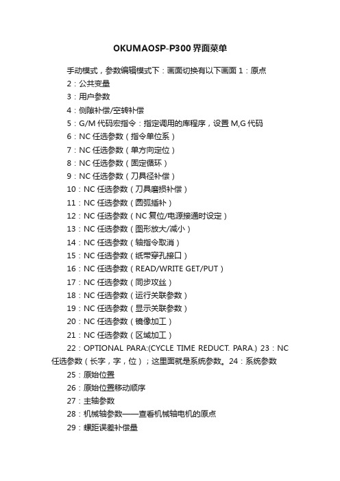
OKUMAOSP-P300界面菜单手动模式,参数编辑模式下:画面切换有以下画面1:原点2:公共变量3:用户参数4:侧隙补偿/空转补偿5:G/M代码宏指令:指定调用的库程序,设置M,G代码6:NC任选参数(指令单位系)7:NC任选参数(单方向定位)8:NC任选参数(固定循环)9:NC任选参数(刀具径补偿)10:NC任选参数(刀具磨损补偿)11:NC任选参数(圆弧插补)12:NC任选参数(NC复位/电源接通时设定)13:NC任选参数(图形放大/减小)14:NC任选参数(轴指令取消)15:NC任选参数(纸带穿孔接口)16:NC任选参数(READ/WRITE GET/PUT)17:NC任选参数(同步攻丝)18:NC任选参数(运行关联参数)19:NC任选参数(显示关联参数)20:NC任选参数(镜像加工)21:NC任选参数(区域加工)22:OPTIONAL PARA:(CYCLE TIME REDUCT. PARA.) 23:NC 任选参数(长字,字,位);这里面就是系统参数。
24:系统参数25:原始位置26:原始位置移动顺序27:主轴参数28:机械轴参数——查看机械轴电机的原点29:螺距误差补偿量30:机床轴螺距误差补偿31:主轴过载监视参数32:攻丝扭矩监视参数33:主轴承寿命参数34:主轴承寿命计数器35:伺服调整(SVTUN)36:HI-切削PRO控制参数37:维护——里面修改轴润滑油脂更换时间38:用户维护39:电池数据40:指定位置:设置两个指定位置坐标41:机床用户参数(冷却液)42:机床用户参数(省电/电源切断)43:机床用户参数(计时器)45:机床用户参数(结束蜂鸣器)46:机床用户参数(主轴)47:机床用户参数(ATC/手动换刀)48:机床用户参数(刀库)49:机床用户参数(外部M指令)50:机床用户参数(外部运行计时器)51:机床用户参数(门互锁)52:机床用户参数(轴润滑)53:机床用户参数(系统检查模式):设置手轮移动刀库电机,机械手电机,转台电机,机床其他轴电机,54:机床用户参数(外部程序选择)55:机床用户参数(卡盘、就位确认,尾座)56:机床用户参数(NC轴互锁)57:机床用户参数(APC)58:机床用户参数(附加轴)59:机床用户参数(机械手、装料器I/F)60:机床用户参数(自动灭火装置)61:机床用户参数(测量)62:MC UEER PARA: (SUB PANEL)63:机床用户参数(专用规格)64:自定义参数65:机床系统参数(ATC)65:机床系统参数(APC)65:机床系统参数(原位置)65:机床系统参数(电源顺序)70:机床系统参数(轴切换)71:机床系统参数(换刀臂控制参数)72:机床系统参数(换刀臂扭矩限制参数)73:机床系统参数(机械轴定位点)74:机床系统参数(门)75:机床系统参数(相关NC轴)76:机床系统参数(冷却液)77:MC SYS. PARA:(OPERATION RELATION PARA.)78:MC SYS. PARA:(OSP ECO)手动模式,坐标位置显示模式下:画面切换有以下画面1:运行画面2:当前位置3:主程序4:调度程序5:MDI程序6:现调用进给轴数据7:程序段数据8:动画仿真9:SERVONAVI M:设置自动测量工件重量,过像限调整,准停调整10:HI-切削PRO控制引导11:HI-切削过程监控12:更改模式(PLC控制模式):更改PLC模式,输入密码,进到输入/输出状态界面,在选项菜单里选择强制开,可进行PLC信号点进行强制。
OKUMA程序指令教程
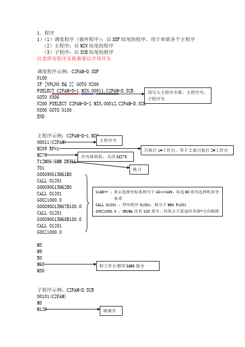
1.程序
1)(1)调度程序(循环程序):以SDF结尾的程序。
用于串联各个主程序(2)主程序:以MIN结尾的程序
(3)子程序:以SUB结尾的程序
注意所有程序名称都要以字母开头
调度程序示例:C2PAM-D.SDF
N100
N300 GOTO N100
END
M5
M9
子程序示例:C2PAM-D.SUB
O0101(C2PAM)
(VIISTE M3 PIIRILEVYPINTA)
X-217.27Y67.13
X-78.64
X-3.94
X122.96Y69.95
注意所有程序段中不能出现G80指令,否则主轴停转。
取消G81等循环指令直接用G01G00等模态指令。
2)程序内可以设定局部坐标系(可以旋转坐标系)
(1)G11 (2)格式:G11 X Y Z P (3)取消G10
3)常用指令(OUKMA 表述不一样的指令)
(1)M53 :指定点回归,循环指令前需用G71指定Z (2)M54 :R 点回归,相当于G99
(3)G84 :浮动攻丝
(4)G284 :同步攻丝(即刚性攻丝)
(5)M329 :主轴无刀互锁无效
(6)M334 :屏蔽换工作台,(MDI 方式下可设定工作台准备)
(7)M19 :主轴定位,M19 RS** 可主轴定位任意角度
注意:无论主轴无刀还是刀库刀位无刀都需先设定M329主轴无刀互锁无效,再进行换刀。
否则换刀不执行。
OKUMA操作说明书模板
- 紧凑型超薄单色显示屏操作面板
- 紧凑型超薄彩色显示屏操作面板
根据NC规范,某些操作面板不可选。
(4)加工管理功能(MacMan)
NC强大的管理功能允许有效使用NC功能。管理功能主要目标为小批量多型号的工件和定量生产多型号的工件产生利润。
(a) 减少调整时间
- 当小批量生产工件时,加工数据需经常变化。为应付这种费时且易于出错的工作,相同的操作步骤Okuma引入不同的软盘格式,并在目录下选择文件名。
车床:X轴和Z轴(两轴同时)
多功能:X轴、Z轴和C轴(3轴同时)
最大同时可控制轴数目
3轴
3轴
可控制轴最大数目
4轴
18轴
装载臂控制轴
可控制最大轴数目
2轴
6轴
可控制轴总数
6轴
24轴
位置编码
OSP绝对位置编码(无需回参考零点)
●
●
控制系统数目
主轴1-刀塔1 主轴1-刀塔2
主轴2-刀塔1 主轴2-刀塔2
同时可控制轴最大数目
1.机床安装过程中的预防措施
(1)为保障机床保证的精度,安装机床的地基周围条件为:
- 周围环境温度:17°C~25°C。
- 工厂湿度:在20°C时40%~70%(非压缩空气)。
- 地基处不能阳光直接照射或震动过大;周围应无尘、无酸、腐蚀性气体和盐雾环境。
(2)主供电源条件
- 电压:200V
- 电压波动:最大±10%
危险:表明突然出现危险情况,如不能避免会导严重致伤亡事故。
警告:表明出现危险情况,如不能避免会导致严重伤亡事故。
警觉:表明出现危险情况,如不能避免会导致轻微受伤或损坏设施/设备。
OKUMA程序运行
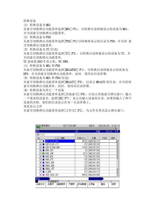
转换设备(1) 转换设备为MD1从索引切换弹出功能菜单选择[MD1](F1),以转换目录将被显示的设备为MD1,并关闭索引切换弹出功能菜单。
(2) 转换设备为FD0从索引切换弹出功能菜单选择[FD0](F2)以转换将显示的目录为FD0,并关闭索引切换弹出功能菜单。
(3) 转换设备为TC(任选)从索引切换弹出功能菜单选择[TC](F3),以转换目录将被显示的设备为TC,并关闭索引切换弹出功能菜单。
TC意味着DNC-T的主机,PC/EWS。
(4) 转换设备为MD1和FD0从索引切换弹出功能菜单选择[MD1&FD0](F4),以转换目录将被显示的设备为DF0,并关闭索引切换弹出功能菜单。
此时,使用双目录屏幕。
(5) 转换设备为MD1和FD0(任选)从索引切换弹出功能菜单选择[MD1&TC](F5),以显示MD1&TC的目录,并关闭切索引切换弹出功能菜单。
此时,使用双目录屏幕。
(6) 转换设备为其它一个设备从索引切换弹出功能菜单选择[其他索引](F6),以显示其他索引弹出窗口。
输入一个要求的设备名,选择[OK](F7)。
显示出输入设备的目录。
如果你输入了两个设备的名称,他们的目录显示在双—目录屏幕上。
变更显示文件从索引切换弹出功能菜单选择[文件名](F2),为文件名型式显示弹出窗口。
当需要的文件类型在弹出功能菜单中被选择的时候,弹出功能菜单关闭,一个只包含有所选类型文件的目录被显示。
分类文件从索引切换弹出功能菜单选择[排序](F3),为文件筛选显示弹出功能菜单。
1.当[文件名](F1)被选择的时候,数据表项目依照文件名的字母顺序被列出,弹出功能菜单关闭。
2.当[容量](F2)被选择的时候,数据表项目依照文件大小被列出,弹出功能菜单关闭。
3.当[日期(升序)](F3)被选择的时候,数据表项目依照年代顺序被列出,弹出功能菜单关闭。
4.当[日期(降序)](F4)被选择的时候,数据表项目依照反向年代顺序被列出,弹出功能菜单关闭。
OKUMA操作说明书.
CNC SYSTEMSOSP-U100LOSP-U10L机床操作手册第2版出版号NO.4196-E-R1 (LE32-065-R2)2000-7上海一阳五金制造有限公司总工程师办公室翻译:沈友兵批准:刘保良安全预防措施本机器装备安全设备用于保护由于某些不可预见的事故造成员工和机器本身损伤。
然而操作工不能仅依靠这些安全设备,其必须十分熟悉下面列出的安全制度,以确保无故障操作。
1.机床安装过程中的预防措施(1)为保障机床保证的精度,安装机床的地基周围条件为:-周围环境温度:17°C~25°C。
-工厂湿度:在20°C时40%~70%(非压缩空气)。
-地基处不能阳光直接照射或震动过大;周围应无尘、无酸、腐蚀性气体和盐雾环境。
(2)主供电源条件-电压:200V-电压波动:最大±10%-频率:50/60Hz-主电源不能同其它主要噪音源(如电焊机、变压接在同一配电柜上,否则会造成NC单元故障。
-机床接地端不能同其它设备接地端公用。
如不得以需同其它设备工共用接地端,该种设备不能是大的噪音源(如电焊机、变压器)。
(3)安装环境安装电控柜时遵循以下几点:-保证NC单元不受阳光直接照射。
-保证电控柜不被溅上切屑、水或油。
-保证电控柜和操作面板不受大的晃动或震动。
-电控柜周边环境温度允许变化范围0°C~40°C。
-电控柜周边湿度允许变化范围30%~95%(非压缩空气)。
-电控柜使用最大海拔高度1000m。
2.上电前检查项(1)关上电控柜和操作面盘上的所有门,以防水、切屑、和尘埃进入。
(2)在操作机床前必须保证机床可动件周围无人,以及机床周围无障碍物。
(3)上电前先接通主电源,接着合上操作面板上”控制开”。
3.手动操作和连续运转预防措施(1)一直遵从操作手册指导。
(2)任何安全罩(前防护门、卡盘罩等)拆除后不能操作盖机床。
(3)在才是操作机床前关上前防护门。
(4)新程式未经通过检查前禁止运行。
Okuma Program Scheduler 用户手册说明书
Okuma America CorporationOkuma Program SchedulerSoftware User ManualRevision HistoryOkuma Program Scheduler 1Revision History 21.Introduction 41.1Purpose 41.2Scope 41.3Definitions, Acronyms and Abbreviations 41.4Overview 41.5References 41.6Requirements 42.Installation 42.1Installation of THINC-API 42.2Installation of Okuma Program Scheduler Interface Software 52.2.1Installation of Microsoft .NET Framework 4.0 52.2.2Installation of Okuma Program Scheduler Interface Software 63.Repair/Uninstall Okuma Program Scheduler Interface Software 93.1Un-install Okuma Program Scheduler Interface Software 94.Installation Files 104.1Okuma Program Scheduler Interface Software 10age 105.1Start Okuma Program Scheduler Interface Application 115.2Exit Okuma Program Scheduler Interface Application 125.3Source Programs and Selected Programs 135.3.1Source Programs 135.3.2Selected Programs 145.4File Name Extension 165.5Output Schedule Program File Name in MD1 Folder 175.6Preview SDF Program 175.7Menu Bar 185.7.1File 195.7.2Browse Folder 195.7.3Refresh Folder 205.7.4Minimize to system tray 205.7.5Generate SDF 215.7.6Save 215.7.7Save and Select 215.7.8About 215.8Configuration 226.TroubleShooting 226.1Logs 226.2Running Statuses of THINC-API 236.3Version 24Okuma Program Scheduler InterfaceUser Manual1. Introduction1.1 PurposeThe purpose of this document is to provide the instruction of installing and operating Okuma Program Scheduler Interface. It also provides information on how to repair, and uninstall this software.1.2 ScopeThis manual will cover the installation, operation and troubleshooting of Okuma Program Scheduler Interface running on OSP P200L/P300L/P200M/P300M/P300G controls or newer controls and on Windows XP SP3, Windows 7 SP1, and Windows 10.1.3 Definitions, Acronyms and AbbreviationsNone1.4 OverviewThe Okuma Program Scheduler Interface is an application that is designed to simplify the process of creating schedule program for part programs stored in D:\MD1 folder and subfolders. Part programs stored in other folders will be copied to the D:\MD1 folder, automatically.1.5 References[1] Installation Manual for THINC-API1.6 RequirementsTHINC-API:Version 1.21.1 for Lathe and Machining CenterVersion 1.21.1 for Grinder2. InstallationThe following steps in section 2.0 need to be performed in the same order:Installation of THINC APIInstallation of Okuma Program Scheduler Interface’ SoftwareNote: All installation must be either installed directly from CD/DVD disks or copied to the local harddrive.2.1 Installation of THINC-APIThis application requires THINC-API having the same version or greater to be installed on machine as specified in the Release Note.Refer to THINC-A PI ‘InstallationManual.pdf’ provided on THINC-API Installation disk for instructions.Tip: Try to run THINC-API Demo Application and see if it runs normally to make sure THINC-API is properly installed.It is always best to install the latest version of THINC-API on the machine if possible.2.2 Installation of Okuma Program Scheduler Interface SoftwareIn Windows mode (press ESC and Cancel button during NC Startup screen to prevent NC from running. On P300A or new controls, it needs to keep tapping on the Shift key while NC is starting to prevent NC from running.), Run the ‘Setup.exe’ program from the DVD to install this software package. The setup program automatically checks if Microsoft .NET framework 4.0 is installed. If it is not installed, continue to section 2.2.1, otherwise refer to section 2.2.2.OSP software should not be running during the installation or .NET Framework 4.0. During the .NET installation, it will be necessary to reboot multiple times. OSP software launch should be cancelled and the installation media should remain connected during the reboot.For Windows XP, it must have Service Pack 3 installed in order to support .NET Framework 4.0This installation can only be installed on 32-bit Windows XP or Windows 7.Note: This setup will check to see if the required version of THINC-API, and Startup Service installed on target machine before installing Okuma Program Scheduler Interface.2.2.1 Installation of Microsoft .NET Framework 4.0The next dialog will be displayed if Microsoft .NET framework 4.0 is not installed.Click Accept to install .NET framework 4.0.If the .NET installation requires rebooting, then it needs to reboot the machine to continue the installation again.2.2.2 Installation of Okuma Program Scheduler Interface SoftwareThe following dialog will be displayed once all of the required .NET frameworks are installed.Click Next to continue.Click Next to continue. User can also select a different folder other than the default one to install Okuma Program Scheduler Interface Software.Click Next to continue. Application is installing.Click Close to complete the installation.3. Repair/Uninstall Okuma Program Scheduler Interface Software3.1 Un-install Okuma Program Scheduler Interface SoftwareStart the machine in Windows only mode. Click Start→Settings→Control Panel to launch control panel. Double click Add or Remove Programs for Windows XP or Programs and Features for Windows 7 in control panel, find the item Okuma Program Scheduler Interface and click Remove or Uninstall to uninstall Okuma Program Scheduler Interface Software.4. Installation Files4.1 Okuma Program Scheduler Interface SoftwareAll the files are installed in the installation folder unless otherwise noted, by default, which is ‘D:\Program files\Okuma\Okuma Program Scheduler’ Interface.5. UsageThis application is designed to help creating schedule program running on OSP-P controls only.Figure: Okuma Program Scheduler Interface Software main user interface for Machining Center5.1 Start Okuma Program Scheduler Interface ApplicationThe Okuma Program Scheduler Interface Software can be launched from the OSP VKEY once NC is fully startup.In addition, application can also be launched from Windows Programs menu by pressing Ctrl + on the operation panel to pop up Start Menu, then click Programs→OKUMA Program Scheduler→Okuma Program Scheduler to run.The main user interface can be displayed by double clicking on the icon in the system tray or Show menu item if the application has been minimized to system tray.5.2 Exit Okuma Program Scheduler Interface ApplicationWhen user shuts down the machine, the software will be terminated automatically without user interaction. Click the button File/Exit will also terminate the software.5.3 Source Programs and Selected ProgramsBy default, the system will list all files in the default D:\MD1 folder based on the current Part Program File Name Extension. User can use the operation buttons to add files to the Selected Programs list or remove files from the Selected Programs list.5.3.1 Source ProgramsThe list displays all files in the current select folder.The source programs displays part programs based on the current selected folder and file name extension.-Add all part programs from source programs to the Selected Programs list-Add one or more selected part programs from source programs to the Selected Programs list-Remove the selected part program from the Selected Programs list-Remove all part programs from the Selected Programs list5.3.2 Selected Programs--Figure: Selected Programs for Machining Center machines-Figure: Selected Programs for Lathe and Grinder machines--Move the current selected row in the Selected Programs list to the first row of the list -Move the current selected row in the Selected Programs list up 1 row-Move the current selected row in the Selected Programs list down 1 row- Move the current selected row in the Selected Programs list to the last row of the list5.3.2.1 Machining Center ProgramsBy default, the part program will be assigned A mode. Mode can be changed to other modes for each part program as shown below:5.3.2.2 Lathe/Grinder ProgramsBy default, the part program will have a repetition of 1. The number of repetition can be changed by changing the value of Repetition column as shown below:5.4 File Name ExtensionBy default, the file name extension is MIN. It can be changed to any other file name extension if the machine is configured to work w ith that. It can also be set to “*” to allow the system to load all files available in the current selected folder. When the folder is refresh or new folder is selected, only files having the same file name extension will be loaded into the Source Programs.5.5 Output Schedule Program File Name in MD1 FolderBy default, the schedule program will be stored in MD1 folder only. A file name must be specified when the schedule program is generated by pressing the GENERATE SDF button.5.6 Preview SDF Program-Figure: Preview SDF Program for Machining Center machinesFigure: Preview SDF Program for Lathe/Grinder machinesThe system will generate a preview of schedule part program based on the programs from the Selected Programs list.Note: If part program files are not stored in the folder or subfolders of D:\MD1, part program files will be automatically copied to the D:\MD1 folder when schedule program is saved.5.7 Menu BarThe application contains a menu bar as shown below. The menu item can be activated by pressing on it or pressing the correspond Function Key from [F1] to [F9] if applicable.5.7.1 File- Click on this soft key or function key [F1], the File menu has one submenu item, which is Click on Exit button close the application.The application can also be closed by clicking the button on the application’s title bar5.7.2 Browse FolderBy clicking on this soft key or function key [F2], a dialog is displayed to allow user to select a folder where part programs can be selected to create a schedule program.When a folder is selected, the system will display all files having file the name extension defined in the Part Program File Name Extension as shown below:If the File Name Extension is *, then all files includes in the current select folder will be displayed in the list.5.7.3 Refresh FolderBy clicking on this soft key or function key [F3], the system will reload all files based on the file name extension and current selected folder.5.7.4 Minimize to system trayClick on this soft key or function key [F4] the main user interface is hidden and theOkuma Program Scheduler icon for this application is shown in the system tray of Windows System task bar.5.7.5 Generate SDF∙Click on this soft key or function key [F5] the system generates a preview of schedule program based on the programs listed in the Selected Programs list.5.7.6 Save∙Click on this soft key or function key [F6] the system will generate and save the schedule program to the MD1 folder based on the Preview SDF Program. A schedule program name without extension must be assigned before performing this operation.Note: The system will also copy part program files to D:\MD1 folder if files are not stored D:\MD1 folder or its subfolders.5.7.7 Save and Select∙Click on this soft key or function key [F6] the system will generate and save the schedule program to the MD1 folder based on the Preview SDF Program. A schedule program name without extension must be assigned before performing this operation. In addition, the scheduleprogram is also loaded into NC.Note: The system will also copy part program files to D:\MD1 folder if files are not stored in D:\MD1folder or its subfolders.5.7.8 About∙Click on this soft key or function key [F8] a dialog is displayed to show the information about this application.5.8 ConfigurationBy default, the file name extension is MIN. If it is changed it will be saved into the application configuration file named OkumaProgramScheduler.exe.config.6. TroubleShooting6.1 LogsBy default, the application will log all messages into the Event Log as shown below.In addition, a log file is also created in the Logs folder where the application is installed. The events inthe log file will be deleted when the application is first started. The name of the log file is Log.txt.6.2 Running Statuses of THINC-APIAfter NC is fully started, THINC-API Notifier Status should have a green icon displayed at the lower left corner of the screen as shown below:Windows XP:Windows 7:Note: The API icon status can only be supported on Windows 7 if THINC-API installed on targethas a version 1.17.1.0 or greater.If the color of icon is red, THINC-API has encountered an error state. By clicking on the API icon, a dialog will display and show detail error message as shown in the captured image below:Please contact OKUMA distributor for further assistant on THINC-API error.6.3 VersionThe version of THINC-API can be checked by clicking on the API icon. A dialog will be displayed and showing API version number.。
OKUMA伺服手册
驱动装置运动控制系统(MCS)/(MCSII)维护手册(第5版)出版号 SC34-006-R5 May 2004安全注意事项安全注意事项本手册说明的控制器包含电气装置部分。
为防止不正确的连接而产生的事故(机械故障或电气部件的烧毁等),请仔细阅读本手册并遵守以下几点。
(1)在连接/断开或拆下一个装置前,要关闭所有电源并将充电装置中的部件放电。
否则,会造成人员的伤害或装置的故障甚至烧毁。
(2)检查要连接电源规格。
如果电压与此装置的要求不相符或者极性接反,均可导致电气装置的故障烧毁。
(3)正确连接各装置的输入和输出线路。
如果出现连接错误,则可能导致电气装置的故障或烧毁。
(4)确保电气装置接地与控制柜接地。
否则,一旦发生漏电,将导致人员触电。
(5)为电气装置连接的电源安装过电流保护装置(断路器、保险丝)。
否则,一旦发生短路会导致电缆及电气装置的烧毁甚至引发火灾。
(6)应确保使用高质量的电源电缆并使之与所用电气设施规格相匹配。
如果电缆电流容量不够,会导致电缆过热乃至烧毁还会引起火灾。
(7)控制柜和操作柜应防水防尘。
否则,会造成人员的伤害或装置的故障甚至烧毁。
(8)电气装置中应配备恒温器来保护装置。
否则,可导致装置烧毁或引发火灾。
本手册采用以下警告标识,提醒你注意一些特别重要的信息。
请仔细阅读带有这些标识的说明并遵照执行。
妥善保管此手册,在需要时,可随时参见手册中内容。
手册内容可由于产品的不断更新而发生变化。
:表示存在严重危险,如果不加避免,则将导致死亡或严重伤害。
:表示危险,如果不加避免,则将导致死亡或严重伤害。
:表示危险,如果不加避免,则将导致人员轻伤或设备的损坏。
:表示操作或使用时的注意事项。
目录A. MIV 装置B. MIP 装置这套书包含的几本手册或许包含了并不适用本机的规格。
因此阅读时请确认与本手册规格相符或相近的内容。
目录A. MIV装置第 1章变频器装置(MIV装置) (1)1.系统配置 (1)2.MIV装置分类 (2)2-1.MIV装置命名 (2)2-2.MIV装置配置 (3)2-3.MIV装置结构 (6)2-4.不同电机类型的MIV装置选型表 (8)3.更换装置的注意事项 (11)3-1.一般注意事项 (11)3-2.装置更换步骤 (12)4.运行状态显示 (14)4-1.状态显示LED排列 (14)4-2.显示内容 (15)4-3.故障代码表 (18)5.控制器ID编码 (32)6.波形监视器描述 (35)6-1.进给轴/刀架/机床轴的MIV装置 (35)6-2.主轴/动力主轴/副主轴的MIV装置 (37)6-3.SWM 监视器装置 (39)7.连接 (44)7-1.系统连接 (44)7-2.接线盒螺钉尺寸 (46)7-3.连接器 (46)8.MIV 装置外形尺寸 (49)8-1.用于BL电机的MIV 装置(单轴规格) (49)8-2.用于BL电机的MIV 装置(双轴规格) (50)8-3.用于VAC电机的MIV 装置(单轴规格) (50)第 2章DC电源装置(MPS,MPR装置) (60)1.系统配置 (60)2.DC电源装置的分类 (61)2-1.DC电源装置的命名 (61)2-2.电源装置配置 (62)2-3.电源装置的结构 (63)3.更换装置注意事项 (65)4.运行状态显示 (67)4-1.状态显示LED的排列 (67)4-2.显示内容 (68)4-3.故障码表 (69)5.控制器ID编码 (71)6.监视器终端描述 (72)6-1.监视器终端排列 (72)6-2.监视器信号 (73)7.连接 (74)7-1.系统连接 (74)7-2.接线盒螺钉尺寸 (74)7-3.连接器 (74)8.DC电源装置外形尺寸 (75)8-1.MPS装置 (75)8-2.MPR装置 (75)第 3章附录1 更换外部冷却风扇步骤 (81)1.故障诊断 (81)2.零件编号 (81)3.更换步骤 (82)3-1.更换MIV06~MIV22和MPS10~MPS30冷却风扇步骤 (82)3-2.更换MIV30、MIV45、MPS45和MPS60外部冷却风扇步骤 (84)4.注意 (85)B. MIP装置第 1章MIP装置 (86)第 2章系统配置 (87)第 3章MIP装置类型 (88)1.装置命名 (88)2.MIP装置配置 (88)3.MIP装置结构 (89)4.可适用电机 (91)第 4章更换MIP装置注意事项 (92)第 5章运行状态显示 (93)1.状态显示LED的排列 (93)2.运行状态显示(变频器控制侧) (94)2-1.正常运行状态显示 (94)2-2.警告状态显示 (95)3.故障码表(变频器控制侧) (96)3-1.例外故障码表 (96)3-2.报警代码表 (98)3-3.警告代码表 (107)4.运行状态显示(DC电源控制侧) (109)4-1.正常运行状态显示 (109)4-2.警告状态显示 (109)5.故障代码表(DC电源控制侧) (109)第 6章监视器终端 (111)1.监视器终端布局 (111)2.监视器终端信号 (112)第 7章连接 (114)第 8章MIP装置外形图 (118)A.MIV 装置第1章变频器装置(MIV装置)Okuma 运动控制系统(MCS)由一个变频器装置和一个DC电源装置组成。
OKUMA操作说明书模板
说明
OSP10L
OSP100L
程序选择
选择一存储的程序
●
●
调度程序
存储的多个程序调度运行顺序
●
●
程序段序号检索
从规定的程序段号起开始切削加工
●
●
MID-自动、手动模式&自动重启
自动模式下允许手动干预。
手动干预结束后从干预位置程序重启自动模式
●
●
多任务过程
加工过程中允许新建/编辑程式和编程加工交互操作
本章讲述下面项目:
程式操作方法、顶点偏移和刀具偏移设定、数据输入/输出和文件编辑方法。
Ⅳ. 参数
本章讲述NC单元所使用的参数及其设定步骤。
Ⅴ. 附录
本章讲述机床操作面板开关和状态指示灯外观布置。
1.OSP规格
(1)基本功能
●:标准功能
○:可选功能
×:不可选功能
项目
说明
OSP10L
OSP100L
控制轴数
b)CNC系统扩展功能使其适用于任何型号机床和CPU结构规范。
c)内置PLC结构用于机床控制
(2)可靠性和紧凑性
采用创新硬件UCMB、I/O接口和伺服系统接口,实现NC紧凑时具备高可靠性。
用闪存实现OSP”多样化软件”功能。安装在用户车间后,升级OSP满足用户新的要求
(3)NC操作面板
提供下列三种型号可选操作面板:
未出现报警时,按帮助键在屏幕上显示报警信息历史记录,也可显示规定报警编号的信息。
【手册内容】
手册由下面五部分组成
Ⅰ. 综述
本章讲述NC特点、规格表单和OSP操作流程图表。
Ⅱ. 操作
本章讲述下面项目:
NC操作面板功能、机床信息显示、机床手动造作方法、MDI、机床自动模式运行和其它操作功能。
OKUMA操作说明书
CNC SYSTEMSOSP-U100LOSP-U10L机床操作手册第2版出版号NO.4196-E-R1 (LE32-065-R2)2000-7上海一阳五金制造有限公司总工程师办公室翻译:沈友兵批准:刘保良安全预防措施本机器装备安全设备用于保护由于某些不可预见的事故造成员工和机器本身损伤。
然而操作工不能仅依靠这些安全设备,其必须十分熟悉下面列出的安全制度,以确保无故障操作。
1.机床安装过程中的预防措施(1)为保障机床保证的精度,安装机床的地基周围条件为:-周围环境温度:17°C~25°C。
-工厂湿度:在20°C时40%~70%(非压缩空气)。
-地基处不能阳光直接照射或震动过大;周围应无尘、无酸、腐蚀性气体和盐雾环境。
(2)主供电源条件-电压:200V-电压波动:最大±10%-频率:50/60Hz-主电源不能同其它主要噪音源(如电焊机、变压接在同一配电柜上,否则会造成NC单元故障。
-机床接地端不能同其它设备接地端公用。
如不得以需同其它设备工共用接地端,该种设备不能是大的噪音源(如电焊机、变压器)。
(3)安装环境安装电控柜时遵循以下几点:-保证NC单元不受阳光直接照射。
-保证电控柜不被溅上切屑、水或油。
-保证电控柜和操作面板不受大的晃动或震动。
-电控柜周边环境温度允许变化范围0°C~40°C。
-电控柜周边湿度允许变化范围30%~95%(非压缩空气)。
-电控柜使用最大海拔高度1000m。
2.上电前检查项(1)关上电控柜和操作面盘上的所有门,以防水、切屑、和尘埃进入。
(2)在操作机床前必须保证机床可动件周围无人,以及机床周围无障碍物。
(3)上电前先接通主电源,接着合上操作面板上”控制开”。
3.手动操作和连续运转预防措施(1)一直遵从操作手册指导。
(2)任何安全罩(前防护门、卡盘罩等)拆除后不能操作盖机床。
(3)在才是操作机床前关上前防护门。
(4)新程式未经通过检查前禁止运行。
OKUMA数控铣床操作手册
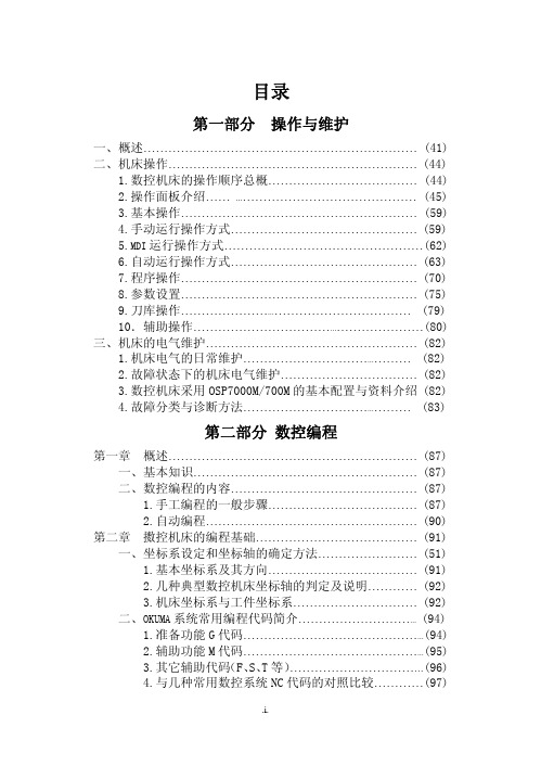
目录第一部分 操作与维护一、概述 (41)二、机床操作 (44)1.数控机床的操作顺序总概 (44)2.操作面板介绍 (45)3.基本操作 (59)4.手动运行操作方式 (59)5.MDI运行操作方式 (62)6.自动运行操作方式 (63)7.程序操作 (70)8.参数设置 (75)9.刀库操作 (79)10.辅助操作 (80)三、机床的电气维护 (82)1.机床电气的日常维护 (82)2.故障状态下的机床电气维护 (82)3.数控机床采用OSP7000M/700M的基本配置与资料介绍 (82)4.故障分类与诊断方法 (83)第二部分 数控编程第一章 概述 (87)一、基本知识 (87)二、数控编程的内容 (87)1.手工编程的一般步骤 (87)2.自动编程 (90)第二章 擞控机床的编程基础 (91)一、坐标系设定和坐标轴的确定方法 (51)1.基本坐标系及其方向 (91)2.几种典型数控机床坐标轴的判定及说明 (92)3.机床坐标系与工件坐标系 (92)二、OKUMA系统常用编程代码简介 (94)1.准备功能G代码 (94)2.辅助功能M代码 (95)3.其它辅助代码(F、S、T等) (96)4.与几种常用数控系统NC代码的对照比较 (97)第三章 基本的编程方法 (98)一、几个基本概念 (98)1.尺寸设定单位 (98)2.绝对坐标和增量坐标 (98)3.进给速度指定 (98)二、数控加工程序的结构及格式 (98)1.程序的组成 (98)(1)程序名与文件名 (99)(2)顺序号 (100)2.程序段格式 (100)3.主程序与子程序 (100)三、部分功能详述 (101)1.工件坐标系的选择 (101)2.工件坐标系的变更 (102)3.工件坐标系的平移和旋转 (102)4.快速定位与直线插补 (103)5.圆弧插补 (104)6.刀具长度补偿 (105)7.刀具半径补偿 (105)8.固定循环 (106)9.可编程镜像加工 (110)10.公共变量与IF语句 (110)第四章 编程实例 (112)一、实例1 (112)1.常用编程指令 (112)2.工作精度内容 (112)3.定位精度说明 (113)4.NC程序及中文注释 (113)(1)精切圆 (113)(2)精切斜方 (114)(3)精镗孔距 (116)(4)测试X方向定位精度 (118)(5)测试Y方向定位精度 (119)(6)测试Z方向定位精度 (120)二、实例2 (121)数控铣床讲义第一部分操作与维护编制:王孙安周嵘2002年3月一、概述OSP7000M/700M是日本OKUMA公司专门为铣床配置的数控系统,具备强大的功能,并且可靠稳定,是当今最成熟的数控系统之一。
OKUMA CNC自动化指南说明书
OKUMA GUIDECNC AUTOMATIONAUTOMATION IN MANUFACTURING, THE USE OF COMPUTER-CONTROLLEDEQUIPMENT AND SOFTWARE TO PERFORM MANUFACTURING PRODUCTIONPROCESSES, was developed to improve quality, efficiency, and productivity inmanufacturing operations.From loading and unloading to conveyor or pallet systems, automation allows you to optimize the flow of production without an operator performing repetitive tasks.The following is a guide to all types of automation—when it was created,how it has evolved, and how it can benefit your shop.With precise actionsand timing, automationeliminates human errorfor seamless, highlyaccurate manufacturing.01 WHAT IS CNC AUTOMATION?Automation in manufacturing is not just the act of moving parts in and outof a machine. It involves designing an entire system to perform routine tasks automatically. From the planning phase, with software and control tools thatdrive data, to execution with robots or automation systems fulfilling those functions, automation takes steps to simplify manufacturing processes andbring consistency to routine operations.Leveraging CNC automation on the shop floor allows machines to do what they do best and people to do what they do best.An operator in front of a machine performing repetitive tasks such as loadingand unloading will never be as productive and consistent as a machine performing the same work. When these types of processes are automated,an operator can perform tasks that a machine can’t, such as critical process decision-making. In its best form, automation does not take away jobs; it allows for a more productive shop floor where machines and people are able to dotasks at which they are most efficient.02 THE HISTORY OF CNC AUTOMATIONThe idea of lights out manufacturing entered themanufacturing vocabulary by engineers in the late 1980s.In the beginning, automotive manufacturers were some ofthe earliest adopters, but today, the automation that makeslights out manufacturing possible is found in a wide varietyof industries and companies of all sizes.When working with some of the earliest automationsystems, every pickup point had to be taught to the robot.It was a time- and labor-intensive process which requireda dedicated robot programmer or integrator to manage, aswell as multiple technicians to keep them running.T oday, AI technology plays a key role in automation, bringing a level of smart decision-making and adaptability to manufacturing that previously wasn’t possible.03 BENEFITS OF CNC AUTOMATIONAny automation solution you seek to implement is designed to create a variety of benefits. With the ability to optimize your manufacturing processes, CNC automation solutions can increase your shop’s productivity, efficiency, and accuracy--and limit downtime, too. Shops that adopt automation also experience increased machine tool ROI. For example, when the market priceof a part or product is predetermined, the only way to ensure you’re getting the maximum ROI is to produce more parts than your competitors and ultimately lower costs.CNC automation can have a powerful impact on operators and other shop floor staff. Anything that is repetitive is a good candidate for automation—not just because automation brings efficiencies and results in reduced downtime, but because it can improve the operators’ physical and mental health when they’re no longer doing the same repetitive tasks and can focus on complex projects.Experience all the benefits automation can bring to your shop floor, including:• TACKLE MORE WORKMaximize spindle utilization. Automation enables continuous machining, which greatly increasesproduction efficiency, even during non-operational hours.• INCREASED PROFITABILITYLess time and material spent per part, lessdowntime, and more efficient operator utilization will lead to reduced costs.• REDUCED DOWNTIMEWith reduced human intervention, the risk ofmaking mistakes and the likelihood of unwanted downtime are decreased.• ATTRACT TALENTAppeal to and maintain a highly skilled workforce with engaging tasks, ergonomics, and safety. • SAVE ON UTILITIESOverhead costs such as lighting, HVAC, and even floor-space requirements can be reduced.• REDUCE SCRAPReducing human interaction provides greaterconsistency and lowers error rates.• INCREASED CONSISTENCY AND ACCURACY An automated machine will be more precisebecause of less human error and fewer setups,resulting in consistency across the board.• INCREASED COMPETITIVE ADVANTAGE The ability to produce the highest quality partpossible with high efficiency sets your shop apartfrom the competition.For manufacturers with high-volume production, introducing automation on the shopfloor can have a strong impact since the time savings from an automation solution canresult in more parts being made over time.And, for manufacturers with low-volume, high-mix production, an automated machinecan internalize functions that would otherwise be spread across several differentmachines. By putting those functions in a single machine, you simplify the automation.All you need is to get the part in and out of that machine.04 WOULD YOUR BUSINESS BENEFIT FROM CNC AUTOMATION?Automation has a wide variety of applications—manufacturers in any industry canutilize automation and see positive results. The scale of the improvement depends onthe type of manufacturing, level of production, and type of automation system utilized.It’s important to analyzewhere changes needto be made and wheremanufacturers wantto create efficienciesto identify the bestautomation solution tofit those needs.05 CONSIDERATIONS FOR INTRODUCINGCNC AUTOMATIONDuring considerations to add automation to your shop floor, it’s important to know baseline productivity to seek out benefits and make improvements. How much does it cost to make your part? What is your current spindle run time? Once you’ve established your current baseline, you can look ahead to how you can improve, whether that’s by cost, time, or streamlining labor.When you understand opportunities for improvement, you can easily identify anything in your processthat’s standing in the way of achieving success, take measures to fix those areas, and implement automated processes that will help you meet your goals.Start with the simplest, most recognizable barriers to meeting your goals. Once you’ve fixed the most obvious problems, you can track the data, see improvements, and potentially identify more areas that can be optimized.06 IMPLEMENTING CNC AUTOMATIONThere are many ways CNC automation can be implemented on the shop floor. In most machines, automation technology is built-in, allowing you to work on the machine and the automation controls simultaneously.In other cases, and for manufacturers who want to automate machines currently on their shop floor, a custom automation solution can be implemented.Depending on the type of machine you’re looking to automate, certain types of automation will serve a different purpose and will match better with certain machines.Prior to implementing an automation solution, operators and other technicians need training not only on the ins and outs of the machines but also on the new technologies they’ll be using. For a turnkey multi-robot system or a load-and-go system, it’s important to have training on your machine’s new automation functionality.BAR FEEDERS are an entry-level automation solution for most Okumalathes in a low-mix, high-production manufacturing environment. Witha consistency of production, bar feeders can provide regular time andmaterial savings over the course of operations, bringing higher efficiencyand leading to cost savings.AUTOMATIC PALLET CHANGERS use stationary pallet stands and apallet transfer unit on the compact structure of a single-level storagesystem to provide flexibility and productivity in a minimal footprint. APCscan provide hours of unattended machining for vertical lathes, machiningcenters, and double columns. Choose from in-machine, single-level, ortower APC options.FLEXIBLE MANUFACTURING SYSTEMS seamlessly operate numerousmachines—even different models. FMSs are configured to manufacture avariety of parts and are able to adapt to changing levels of production.OKUMA GANTRY LOADERS don’t have as much flexibility as a roboticcell but are able to perform faster, with a moving headstock that allowsthe loader to enter the machine regardless of turret position. OGLs areperfect for Okuma lathes or grinders. A built-in solution for efficient partload, unload, and turnover, OGLs significantly increase productivity.PRE-KITTED AUTOMATION CELLS are preconfigured automationpackages that are easy to integrate, quick to implement, and designed for all machine tool categories.07 TYPES OF CNC AUTOMATION SOLUTIONSDepending on your shop floor’s needs, different types of automation solutions operate in different waysand at different levels of control. Explore all of the automation solutions that may benefit your shop floor:For more information about Okuma products, contact your local Okuma distributor or schedule an appointment to visit us at one of the following locations:Okuma America Corporation11900 Westhall DriveCharlotte, NC 28278P: 704.588.7000Partners in THINC12428 Sam Neely RoadCharlotte, NC 28278P: 704.587.6789The Okuma Technical Center at Hartwig Houston 10321 Regal Row Houston, TX 77040P: 713.749.9600The Okuma Technical Center at Morris Midwest 2400 Vantage Drive Elgin, IL 60124 P: 630.351.1901© 2023 Okuma America Corporation Contact your local distributor at /distributorsINDUSTRIAL AND INTEGRATED ROBOTICS are pre-engineered solutionsfor straightforward integration with configuration flexibility for specificapplications.COBOTS are a collaborative and customizable automation solution withprogramming, speed, safety settings, and intelligent features for insightsinto smart manufacturing.OKUMA’S ROID SERIES features Okuma’s robot offerings, ARMROIDand STANDROID. ARMROID is built into the machine tool to maintain andstreamline operations. STANDROID is a standalone robot package thatprovides multifunctional and efficient manufacturing on a compact footprint.Both products in the ROID series provide flexibility to innovate at youroptimal level of control.。
OKUMA程序指令教程
OKUMA程序指令教程导言:OKUMA编程指令是用于控制OKUMA数控机床操作的命令集合。
编程指令的正确使用是保证机床运行正确和提高加工效率的关键。
本教程将介绍OKUMA常用的编程指令,并提供一些实例来帮助读者更好地理解和应用这些指令。
1.系统指令:1.1.O标记:用于定义程序的起始位置。
例如,O0001表示第一个程序段的开始。
1.2.G伺服:用于选择主轴的控制方式。
例如,G96表示恒转速控制方式。
1.3.M指令:用于开启或关闭机床功能。
例如,M03表示主轴正转,M08表示冷却液开。
2.运动指令:2.1.G00:快速定位指令,用于将刀具快速移动到指定位置。
2.2.G01:直线插补指令,用于实现直线轨迹的插补运动。
2.3.G02/G03:圆弧插补指令,用于实现圆弧轨迹的插补运动。
2.4.G04:停留指令,用于在指定位置停留一段时间。
2.5.G09:准确停止指令,用于在指定位置精确定位。
2.6.G28:参考点返回指令,用于将刀具回到参考点。
2.7.G53:绝对坐标指令,用于指定刀具位置的绝对坐标。
3.切削指令:3.1.M06:刀具更换指令,用于刀具的自动更换。
3.2.M41/M42:刀具补偿指令,用于开启或关闭刀具补偿。
3.3.M98/M99:子程序指令,用于调用子程序。
3.4.G50:刀具半径补偿指令,用于修正刀具半径误差。
3.5.M06/M07:冷却液开关指令,用于控制冷却液的开启和关闭。
4.辅助指令:4.1.G40:不补偿指令,用于取消之前的刀具半径补偿。
4.2.G54~G59:坐标系选择指令,用于选择机床上的不同坐标系。
4.3.M30:程序结束指令,用于程序的结束和复位。
4.4.G80:取消固定循环指令,用于取消之前设置的固定循环。
4.5.G98/G99:进给速率选择指令,用于选择进给速率的计算方式。
4.6.M00:暂停指令,用于在程序中插入停顿。
总结:本教程介绍了OKUMA常用的编程指令,包括系统指令、运动指令、切削指令和辅助指令。
OKUMA NC 系统 OSP-P300SP300L 基本操作指南 ( 第2 版)
NC系统OSP-P300S基本操作指南 (第2版) Pub No. LC32-162-R2 Sep. 2012安全注意事项本机床配有多种安全装置,操作机床时,可以防止意外事故中人员受伤和机床受损。
然而,所有操作员不能完全依赖安全装置,还必须熟练掌握以下安全准则,以确保无事故操作。
本操作手册和贴在机床上的警告牌仅限于Okuma公司能够预测到的危险。
请注意这并不包括所有可能发生的危险。
1.与安装相关的注意事项(1)请注意以下与主电源相关的注意事项。
∙切勿使机床与易产生高噪声的设备(如电焊机或放电加工机)从同一配电板引出主电源,否则可能导致NC装置故障。
∙尽可能使机床单独接地。
如果机床必须与其它设备共同接地,则不要与容易产生高噪声的设备(如电焊机或放电加工机)共用同一接地端子。
(2)安装环境安装控制柜时,应注意以下事项。
∙确保NC装置不会受阳光直射。
∙确保控制柜不会溅上切屑、水或油。
∙确保控制柜和操作面板不会受到过大振动或撞击。
∙控制柜的允许环境温度范围为5至40°C。
∙控制柜的允许环境湿度范围为50%或更低(40°C时)(无凝露)。
∙控制柜可使用的最大海拔高度为1,000m。
2.接通电源前的检查事项(1)将控制柜和操作面板的门全部关闭以防止水、切屑和灰尘进入。
(2)运行机床前,务必确保机床的运动部件附近无人,且机床周围没有障碍物。
(3)接通电源时,首先打开主电源开关,然后打开操作面板上的加电开关。
3.与手动/连续运行相关的注意事项(1)应遵守操作手册进行操作。
(2)请勿在机床前护罩、卡盘罩或其它护罩拆下的情况下运行机床。
(3)起动机床前应关闭前护罩。
(4)首件加工时,通过按顺序执行空运行->单程序段切削->连续运行,检查操作和各部件干涉。
(5)试图进行主轴旋转和移动操作前要确保安全。
(6)主轴旋转时切勿接触切屑或工件。
(7)切勿用手或其它方式使旋转中的部件停止。
(8)检查液压卡盘爪的安装情况、工作压力和最高允许转速。
Okuma OSP Alarm Notifier说明书
Okuma OSP Alarm Notifier1Okuma OSP Alarm NotifierPrefaceThank you for downloading Okuma OSP Alarm Notifier. This application enables you to receive Okuma machine tool alarm messages via email along with a screen shot of the current state of the CNC controller. This application is one of many examples that showcase the power of the open architecture THINC CNC controller. To learn more about Okuma and the THINC CNC controller please visit Okuma’s web site at . Please take the time to read this document in full and in addition to this take the time to read and understand the Okuma machine manuals.License agreementDISCLAIMER OF WARRANTYALL THE COMPUTER PROGRAMS AND SOFTWARE ARE PROVIDED "AS IS" WITHOUTWARRANTY OF ANY KIND. MORRIS MIDWEST LLC MAKES NO WARRANTIES, EXPRESS OR IMPLIED,THAT THEY ARE FREE OF ERROR, OR ARE CONSISTENT WITH ANY PARTICULAR STANDARDOF MERCHANTABILITY, OR THAT THEY WILL MEET YOUR REQUIREMENTS FOR ANYPARTICULAR APPLICATION.THEY SHOULD NOT BE RELIED ON FOR SOLVING A PROBLEM WHOSE INCORRECT SOLUTIONCOULD RESULT IN INJURY TO A PERSON OR LOSS OF PROPERTY.IF YOU DO USE THEM IN SUCH A MANNER, IT IS AT YOUR OWN RISK.MORRIS MIDWEST LLC, AUTHOR AND PUBLISHER DISCLAIM ALL LIABILITY FOR DIRECT,INDIRECT, OR CONSEQUENTIAL DAMAGES RESULTING FROM YOUR USE OF THE PROGRAMS.UPON USING THIS SOFTWARE YOU AGREE TO THE ABOVE TERMS AND CONDITIONS2Okuma OSP Alarm NotifierINDEX1 SYSTEM REQUIREMENTS……………………………………………………..P41.1 Machine tool system requirments……………………………………P41.2 How to update .NET framwork………………………………………P41.3 How to update THINC API………………………...…………………P51.4 Installing the THINC startup service……………....................………P61.5 GMAIL (Google Mail)……………….……………...…………………P62INSTALLING THE APPLICATION.………..………..…………………………..P72.1 Running setup file………………………....................……………….…P72.2 Where is the application stored.……………………...…………………P83 USING THE APPLICATION……….…………………….……………………..P103.1 Starting the application………………………………………....………P103.2 Entering settings………………………………...........................………P113.3 Running the application………………………..........................………P143.4 Stopping and closing the application…………………...……...………P163.5 Errors and Logging…………………………………………......………P1734Okuma OSP Alarm Notifier1 System requirements1.1 M achine tool system requirementsOkuma OSP controllerP200L,P200LA,P200M,P200MA,P300L,P300S,P300M Windows software requirementsWindows XP Service Pack 3, Windows 7 Service pack 1 THINC API minimum versionTHINC API 1.15.0.0 and THINC Startup Service.NET framework .NET 4.0Google GMAIL account A valid GMAIL (Google Mail) account must be setupYou can register a GMAIL account at https:///Internet connectionA working high speed internet connection is required1.2 H ow to update .NET frameworkUpon running Alarm Notifier setup executable if the system software does not meet the.NET framework requirements the application will prompt you for permission to install.NET framework 4.0. Simply click on the checkbox for reading the and accepting the terms and license and click install.Once the installation is complete you will be required to reboot the machine5Okuma OSP Alarm Notifier1 System requirements continued1.3 H ow to update THINC APIFirst you will need to identify the current version of THINC API installed on the machine.You can do this by opening the taskbar on the machine’s controller by holding the control key (located on the control panel keyboard) down and then press the cancel keyOnce the task bar is opened click on the small API icon and this will open the API notifier that will show the version. Should the API require an update please contact your local Okuma distributor to order the latest versionOkuma OSP Alarm Notifier1 System requirements continued1.4 I nstalling the THINC startup serviceThe THINC startup service is a utility that comes with your Okuma API disc. The THINC startup service will automatically launch THINC API dependent applications only if theTHINC API is initialized. For information on how to install and use the THINC startupservice please read the THINC startup service manual (Okuma publication M911-08-0213-01) located on the THINC API disc.1.5 G mail (Google Mail)This application requires the use of a valid GMAIL (Google Mail) account. To register afree GMAIL account go to your preferred web browser and type GMAIL in the search oryou can navigate directly to the GMAIL site using this address https:///67Okuma OSP Alarm Notifier2 Installing the application continued2.1 Running the setup fileLocate the setup.exe file for the Okuma OSP Alarm Notifier and double click on the application to run it.After executing the setup application proceed through the setup prompts to install the application.8Okuma OSP Alarm Notifier2 Installing the application continued2.2 Where the application is storedDuring the installation of the application the installer will prompt you of the defaultinstallation directory. At this point you may choose a different directory or proceed with the default which is D:\Morris Midwest\Okuma OSP Alarm Notifier9Okuma OSP Alarm Notifier2 Installing the application continued2.2 Where the application settings are storedThe settings of the application are storedWindows XP : C:\Documents and Settings\Local Settings\Application Data\ Morris_Midwest\Okuma_OSP_Alarm_NotifierWindows 7: C:\Users\(Username)\AppData\Local\Morris_MidwestThe user config file is XML format and can be opened with a text editor such as WordPad or notepad; however modifications of the user config file is not necessary10Okuma OSP Alarm Notifier3 Using the application3.1 Starting the applicationTo start the application navigate to the start menu and programs\Morris Midwest\ Okuma OSP Alarm Notifier and click on the icon to run the application.Note: A shortcut is also created on the desktopOkuma OSP Alarm Notifier 3 Using the application continued3.2 Setting up the applicationOnce the application is open the screen should show like below.Click on the modify button to unlock the textbox fields11Okuma OSP Alarm Notifier3 Using the application continued3.2 Setting up the application continuedNext click on the settings tab and fill out your GMAIL account info. This will be theaccount the application uses to send emails from.Next check box which alarm class levels you wish to receive emails on and if you wantthe application to start monitoring at the startup of the application you can check the “runat startup” boxNote: If you want the application to auto start at machine startup please refer to theTHINC startup service manual for details12Okuma OSP Alarm Notifier3 Using the application continued3.2 Setting up the application continuedNext click on the main tab and fill out the email account you wish the notification to be sentto along with the subjectstating that the settings have been saved.1314Okuma OSP Alarm Notifier3 Using the application continued3.3 Running the application in monitor modeAfter all the settings are complete we can now place the application in monitor mode by clicking on the monitor button. This will minimize the application to the task bar. You can still display the application by navigating to the task bar and clicking on the applicationDuring monitoring if the application encounters a machine alarm that you wish to receive an email about the application will capture the current screen and send you an email with the screenshot attached as an attachment.Okuma OSP Alarm Notifier3 Using the application continued3.3 Running the application in monitor mode continuedBelow is an example of an email notification received from the application15Okuma OSP Alarm Notifier3 Using the application continued3.4 Stopping and closing the applicationTo stop the application monitoring simply click on the stop button or to close theapplication simply click on the close button1617Okuma OSP Alarm Notifier3 Using the application continued3.5 Errors and loggingAll application errors and events are tracked and logged. You can view the running log by simply clicking on the log tab. You can also view the history of logs by navigating to the application’s root directory and clicking on the log error.txt file。
OKUMA(E100M)网络安装说明
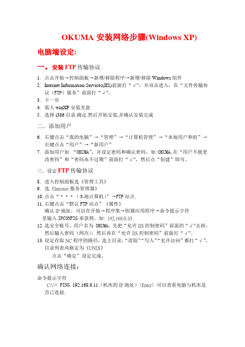
OKUMA安装网络步骤(Windows XP)电脑端设定:一。
安装FTP传输协议1.点击开始→控制面板→新增/移除程序→新增/移除Windows组件2.Internet Information Services(IIS)前面打“√”,并双击进入,在“文件传输协议(FTP)服务”前面打“√”。
3.下一步4.装入winXP安装光盘5.选择i386目录.确定.然后开始安装,并确认安装完成二.添加用户6.右键点击“我的电脑”→“管理”→“计算机管理”→“本地用户和组”→右键点击“用户”→“新用户”7.添加用户如“OKUMA”,并设定密码和确认密码,如:OKUMA,在“用户不能更改密码”和“密码永不过期”前面打“√”,然后点“创建”即可。
三.设定FTP传输协议8.进入控制面板选《管理工具》9.选《Internet服务管理器》10.点击“﹡﹡﹡(本地计算机)”→FTP站点.11.右键点击“默认FTP站点”《属性》确认IP地址,可以在开始→程序集→附属应用程序→命令提示字符里输入IPCONFIG来获得。
如: 192.168.0.1012.选安全账号,用户名为OKUMA,先把“允许IIS控制密码”前面的“√”去掉,然后输入密码(两次),然后再在“允许IIS控制密码”前面打“√”。
13.设定存取NC程序的路径,选主目录,“读取”“写入”“允许访问”都打“√”,目录列表风格定为《UNIX》点击“确定”设定完成。
确认网络连接:命令提示字符C:\>PING 192.168.0.11(机床的IP地址)〈Enter〉可以查看电脑与机床是否已连接.机床设定《E10/100M》1.设定机床的IP地址及子网掩码2.选择《MacMan》→““[P↓]”→“Setup”→“Connection Environment”→“WRITE”→“进入网络设置”3.设定机床的IP地址及子网掩码设置《IP address》→“WRITE”→“192.168.0.11”→“WRITE”选择《Subnetwork address》→“SET”→“255. 255.255.0”→“WRITE”4.设定PC的IP.计算机名用户名密码选择《PARAMETER》→《MacMan PARAMETER》→《DNC-T》选择《Remote-Host》→“SET”→“192.168.0.10”→“WRITE”选择《Host-name》→“SET”→“ES4”(计算机名)→“WRITE”选择《User-Name》→“SET”→“OKUMA”(用户名,要和PC机设定一致)→“WRITE”选择《Password》→“SET”→“OKUMA”→“WRITE”→“SA VE”5.关机→重新起动确认网络连接:1.“开始”→“所有程序”→“命令提示符”→输入:PING 192.168.0.11(机床的IP地址)〈Enter〉可以看计算机舆机床是否连接.若出现“Request timed up”则表示未连接.2.“开始”→“所有程序”→“命令提示符”→输入:FTP 192.168.0.10(电脑IP地址) 〈Enter〉→输入用户名和密码.若出现“用户名LOGGED IN”则表示FTP功能已设置好.否则要再检查.。
- 1、下载文档前请自行甄别文档内容的完整性,平台不提供额外的编辑、内容补充、找答案等附加服务。
- 2、"仅部分预览"的文档,不可在线预览部分如存在完整性等问题,可反馈申请退款(可完整预览的文档不适用该条件!)。
- 3、如文档侵犯您的权益,请联系客服反馈,我们会尽快为您处理(人工客服工作时间:9:00-18:30)。
CNC SYSTEMSOSP-U100LOSP-U10L机床操作手册第2版出版号NO.4196-E-R1 (LE32-065-R2)2000-7上海一阳五金制造有限公司总工程师办公室翻译:沈友兵批准:刘保良安全预防措施本机器装备安全设备用于保护由于某些不可预见的事故造成员工和机器本身损伤。
然而操作工不能仅依靠这些安全设备,其必须十分熟悉下面列出的安全制度,以确保无故障操作。
1.机床安装过程中的预防措施(1)为保障机床保证的精度,安装机床的地基周围条件为:-周围环境温度:17°C~25°C。
-工厂湿度:在20°C时40%~70%(非压缩空气)。
-地基处不能阳光直接照射或震动过大;周围应无尘、无酸、腐蚀性气体和盐雾环境。
(2)主供电源条件-电压:200V-电压波动:最大±10%-频率:50/60Hz-主电源不能同其它主要噪音源(如电焊机、变压接在同一配电柜上,否则会造成NC单元故障。
-机床接地端不能同其它设备接地端公用。
如不得以需同其它设备工共用接地端,该种设备不能是大的噪音源(如电焊机、变压器)。
(3)安装环境安装电控柜时遵循以下几点:-保证NC单元不受阳光直接照射。
-保证电控柜不被溅上切屑、水或油。
-保证电控柜和操作面板不受大的晃动或震动。
-电控柜周边环境温度允许变化范围0°C~40°C。
-电控柜周边湿度允许变化范围30%~95%(非压缩空气)。
-电控柜使用最大海拔高度1000m。
2.上电前检查项(1)关上电控柜和操作面盘上的所有门,以防水、切屑、和尘埃进入。
(2)在操作机床前必须保证机床可动件周围无人,以及机床周围无障碍物。
(3)上电前先接通主电源,接着合上操作面板上”控制开”。
3.手动操作和连续运转预防措施(1)一直遵从操作手册指导。
(2)任何安全罩(前防护门、卡盘罩等)拆除后不能操作盖机床。
(3)在才是操作机床前关上前防护门。
(4)新程式未经通过检查前禁止运行。
卡盘上不夹装工件运行程式确认不出现干涉,然后在”单节执行”模式下切削工件。
如为未发现故障即可在自动运行模式下切削工件。
(5)执行如主轴转动或轴运动等操作之前应确保操作安全。
(6)主轴转动时禁止接触切屑或工件。
(7)禁止试图用手或其它任何物体停止转动的物体。
(8)检查卡盘压爪安装条件、液压油压力和最大许用最大主轴转速。
(9)检查刀具安装和布置。
(10)检查刀具偏移设定。
(11)检查零点偏移设置。
(12)确认NC操作面板上的主轴转速超越率和进给超越率置于100%位。
(13)在移动刀塔前,检查X轴和Z轴行程设定和行程紧急位置开关,保证同卡盘和尾座不出现干涉。
(14)检查刀塔编号和转动方向。
(15)检查尾座位置。
(16)确认在许用传递功率和扭矩范围内执行切削操作。
(17)确认工件在卡盘或固定装置上安全装夹。
(18)检查切削液嘴位置正确。
4.加工工作结束(1)加工工作结束后,清洁机床周围环境。
(2)刀塔退回至预先设定位置。
(3)在离开之前断开机床电源。
(4)首先断开操作面板上的电源,然后断开连接的开关主电源。
5.出现故障时维修检查时采用的预防措施为防止不可预见的故障对机床造成损坏,进行维修检查或出现故障时检修应遵循以下几点:(1)出现故障时按机床上的紧急制动按钮停止机床。
(2)咨询维护负责人员决定需采用何种纠正措施。
(3)如需两个以上人员协同工作时,制订交流信号,在进行每一步操作之前应有安全保障。
(4)使用规定的配件和保险丝。
(5)在开始检修或更换零部件之前断开电源。
(6)在检修或修理零部件时如需拆除零件,应用相同零件替换,并同螺纹正确紧固。
(7)在检修时如需用量具,如电压表。
应保证这些量具正确校正。
(8)禁止在电控柜或终端箱内遗留易燃材料或金属。
(9)检查电缆和电线未损坏,否则会造成漏电和电击。
(10)维修电控柜内设备时:a) 在开启电控柜门之前断开主电源。
b) 即使断开主电源后,伺服放大器和主轴驱动装置中仍残余部分电流,此时只允许服务人员检修检修这些设备,并遵循下列预防措施:-伺服放大器断开内部断路器后应放残余电压一分钟。
-主轴驱动单元断开主电源开关后应放残余电压一分钟。
c) 电控柜包含NC单元,该单元印刷电路板存储器储存加工程式、参数等。
为保证断电之后仍保留该程式,存储器由干电池供电。
存储器根据电路板故障而遭到破坏,此时只有专业服务人员才能处理这些电路板。
(11)电控柜定期检修a) 清洁散热装置电控柜内散热装置起防止电控柜温度过高,提高NC单元可靠性。
每三个月检修以下几项。
-冷却装置风扇马达是否工作?如有强风流则马达工作正常。
-外部空气吸入口是否阻塞?如阻塞吸入口用压缩空气清洁。
6.一般预防措施(1)保持机床及其周边环境清洁有序。
(2)工作时着装合适,并遵从经培训人员指导。
(3)保证衣物和头发不被转入机床。
机床操作员穿着安全,如穿装劳保鞋和手套。
(4)机床操作员在操作机床之前应仔细阅读指导手册,并认可这些步骤。
(5)记住紧急制动按钮位置,以便在任何时候任何位置均能立即按下紧急制动按钮。
(6)由于控制面板、变压器、电机等为高压终端设备,禁止进入这些设备和其它相当危险设备内部。
(7)如需两个以上人员协同工作时,制订交流信号,在进行每一步操作之前应有安全保障。
7.手册中使用标识的含义手册中使用下面警告标识提请需注意的特别重要信息,仔细阅读这些标识的指示并予以遵循。
危险:表明突然出现危险情况,如不能避免会导严重致伤亡事故。
警告:表明出现危险情况,如不能避免会导致严重伤亡事故。
警觉:表明出现危险情况,如不能避免会导致轻微受伤或损坏设施/设备。
注意:需采取预防措施。
介绍Okuma感谢您选用OSP CNC系统,为您成为Okuma用户家族中之一员而自豪。
本手册包含OSP CNC型号机床安装、调试、操作及维护简明内容。
为长时间利用其优良性能,本机床必须安装正确,其操作和维护程序必须理解清晰和认真遵守。
鼓励在机床安装之前仔细学习本指导手册,并形成文件以备今后参考。
内容分类Ⅰ. 综述Ⅱ. 操作Ⅲ. 数据操作Ⅳ. 参数Ⅴ. 附录Ⅰ. 综述第一部分前言在阅读本手册之前,请阅读前言。
本部分讲述机床NC特点、本手册内容结构及阅读时需注意项。
【NC特点】(1) 多CPU系统允许CNC机床功能扩展本NC采用安装多CPU(可达7枚)系统。
a) 功能强大、性价比高可适用先进刀具高速、高进度切削。
b) CNC系统扩展功能使其适用于任何型号机床和CPU结构规范。
c) 内置PLC结构用于机床控制(2) 可靠性和紧凑性采用创新硬件UCMB、I/O接口和伺服系统接口,实现NC紧凑时具备高可靠性。
用闪存实现OSP”多样化软件”功能。
安装在用户车间后,升级OSP 满足用户新的要求(3) NC操作面板提供下列三种型号可选操作面板:-14”彩色CRT显示屏操作面板-紧凑型超薄单色显示屏操作面板-紧凑型超薄彩色显示屏操作面板根据NC规范,某些操作面板不可选。
(4) 加工管理功能(MacMan)NC强大的管理功能允许有效使用NC功能。
管理功能主要目标为小批量多型号的工件和定量生产多型号的工件产生利润。
(a) 减少调整时间-当小批量生产工件时,加工数据需经常变化。
为应付这种费时且易于出错的工作,相同的操作步骤Okuma引入不同的软盘格式,并在目录下选择文件名。
-工件调整工作所必须的指令信息可显示在NC单元显示屏上。
(b) 了解实际加工状态加工状态和机床工况可显示在NC单元显示屏上。
(c) 解决故障的时间解决故障的必需信息可用适当格式准确快速地显示出来,如打印或复制到软盘。
此管理功能详情参考”MacMan 指导手册”。
(5) 帮助功能出现报警时,按帮助键在屏幕上显示报警信息。
未出现报警时,按帮助键在屏幕上显示报警信息历史记录,也可显示规定报警编号的信息。
【手册内容】手册由下面五部分组成Ⅰ. 综述本章讲述NC特点、规格表单和OSP操作流程图表。
Ⅱ. 操作本章讲述下面项目:NC操作面板功能、机床信息显示、机床手动造作方法、MDI、机床自动模式运行和其它操作功能。
Ⅲ. 数据操作本章讲述下面项目:程式操作方法、顶点偏移和刀具偏移设定、数据输入/输出和文件编辑方法。
Ⅳ. 参数本章讲述NC单元所使用的参数及其设定步骤。
Ⅴ. 附录本章讲述机床操作面板开关和状态指示灯外观布置。
1.OSP规格(1) 基本功能●:标准功能○:可选功能×:不可选功能(2) 操作功能●:标准功能○:可选功能×:不可选功能(3) 编程功能●:标准功能○:可选功能×:不可选功能(4) 多轴加工编程功能(具备该M功能机床)●:标准功能○:可选功能×:不可选功能(5) 交互式编程功能(车床自动编程功能)●:标准功能○:可选功能×:不可选功能(6) 程式存储* 不适用于OSP10(7) 加工管理(MacMan)功能●:标准功能○:可选功能×:不可选功能(8) 监测功能●:标准功能○:可选功能×:不可选功能(9) 测量功能(略)(10)外部输入/输出和通信功能(略)(11) 自动和无人操作功能●:标准功能○:可选功能×:不可选功能(12) 高速切削和高精度功能●:标准功能○:可选功能×:不可选功能(13) 其它(略)2.操作流程图表(略)2-1 自动操作模式(A)F1 程式选择在路径选择模式下选择工件的程式F2 实际位置用于显示实际位置坐标F3 工件程式用于显示工件程式F4 单段数据用于显示某一程式段中的数据F5 检索用于选择检查数据F7 检查数据用于显示不同的检查数据扩展翻页大字符显示实际位置数据同时显示实际位置和程式显示实际位置及机床状态和负载条件同时显示其它轴运动和实际位置翻页显示当前选择的刀塔A或B的程式同时显示刀塔A和B的程式MDI模式下通过键盘输入的数据显示调度程式翻页显示当前执行的程式段数据显示下一待执行的程式段数据显示再下一程式段的数上次储存在寄存器中程式段数据翻页显示特殊数据显示与轴相关的数据显示刀具调用时间显示规范号显示进程中测量的数据显示后处理测量的数据显示MCS诊断F8 <扩展功能>F1F2F4F5F7F8数据检索重启调度程式选择在路径选择模式下选择工件调度程式调度程式号选择刀具布置扩展检索程式段号程式段重启准备调度程式号检索显示调度程式用刀具数据<扩展功能>F1F7可用刀具显示调度程式用刀具数据退出结束显示刀具数据F1F3F4F5F7F8标准/放大图形正常比例缩放比例路径/仿真F6 材料填充清除图形扩展用于选择标准或放大的图形显示用于设定标准图形显示的比例用于设定缩放图形显示的比例用于选择刀具路径/仿真图形显示用于显示填充余量,卡盘,尾座用于清除图形显示<扩展功能>(B)(C)(D) (E)2-2 MDI 操作模式`F1 (B)自动比例 F2 随机比例自动设定比例 随机设定比例 F7 退出 结束设定比例模式F1 F2 F7 图幅增大图幅减小 退出比例增大 比例缩小 结束设定比例模式 F1F2 F7F8 负载检测 时间单位 清除 扩展 显示作用在刀具上的瞬时负载 负载图时间轴 清除负载时间关系图 <扩展功能>(A) (A) F1 输入数据在路径选择模式下选择工件的程式 F2 实际位置 用于显示实际位置坐标F3 工件程式 用于显示工件程式 F4 用于显示某一程式段中的数据 F5 用于选择检查数据 检查数据 用于显示不同的检查数据 扩展 F8 <扩展功能>单段数据 F7检索翻页大字符显示实际位置数据 同时显示实际位置和程式 显示实际位置及机床状态和负载条件同时显示其它轴运动和实际位置翻页 显示当前选择的刀塔A 或B 的程式 同时显示刀塔A 和B 的程式 显示MDI 模式下通过键盘输入的数据 显示调度程式翻页显示当前执行的程式段数据 显示下一待执行的程式段数据 显示再下一程式段的数据显示上次储存在寄存器中程式段数据 翻页 显示特殊数据显示与轴相关的数据 显示刀具调用时间 显示规范号显示进程中测量的数据 显示后处理测量的数据 显示MCS 诊断(C) F1 F3 F4 标准/放大图形 正常比例缩放比例用于选择标准或放大图形显示 用于设定标准图形显示的比例用于设定缩放图形显示的比例(B)(D)(E)2-3 手动操作模式F5 F7 F8 路径/仿真 F6 材料填充清除图形 扩展用于选择刀具路径/仿真图形显示 用于显示填充余量,卡盘,尾座 用于清除图形显示 <扩展功能>F1 自动比例 F2 随机比例自动设定比例 随机设定比例 F7 退出 结束设定比例模式F1 F2 F7 图幅增大图幅减小 退出比例增大 比例缩小 结束设定比例模式F1 F2F7 F8负载检测 时间单位 清除 扩展 显示作用在刀具上的瞬时负载 负载图时间轴 清除负载时间关系图 <扩展功能>(A) (C) (A) F2 实际位置 用于显示实际位置坐标F3 工件程式用于显示工件程式 F4 用于显示某一程式段中的数据 F5 用于选择检查数据 检查数据 用于显示不同的检查数据 扩展 F8 <扩展功能>单段数据 F7检索翻页大字符显示实际位置数据 同时显示实际位置和程显示实际位置及机床状态和负载条件同时显示其它轴运动和实际位置 翻页 显示当前选择的刀塔A 或B 的程式 同时显示刀塔A 和B 的程式 显示MDI 模式下通过键盘输入的数显示调度程式翻页显示当前执行的程式段数据 显示下一待执行的程式段数据 显示再下一程式段的数据显示上次储存在寄存器中程式段数翻页显示特殊数据 显示与轴相关的数据 显示刀具调用时间 显示规范号显示进程中测量的数据 显示后处理测量的数据 显示MCS 诊断F3正常比例用于设定标准图形显示的比例F1 标准/放大图形用于选择标准或放大的图形显示(B)(C)2-4 刀具数据设定模式F4 F5 F7F8 缩放比例 路径/仿真 F6 材料填充 清除图形扩展用于设定缩放图形显示的比例 用于选择刀具路径/仿真图形显示 用于显示填充余量,卡盘,尾座 用于清除图形显示 <扩展功能>F1 自动比例 F2 随机比例 自动设定比例 随机设定比例 F7退出结束设定比例模式F1 F2 F7图幅增大 图幅减小 退出比例增大 比例缩小 结束设定比例模式(A)(C)(B)F1F2 F3 F4 F5 F8 F7 F6 数据备份 强制保存刀具设定数据备份 加 常加 项目↓ 扩展 常减 项目↑ 与当前存储的数据相加 参数加 参数减 指导开/关 参数减用于改变刀具数据设定项随刀号选择,可设定和改变刀具偏移/刀尖半径补偿 刀具形状改变刀具寿命管理(刀具信息表) 刀具寿命管理(刀具组表) 显示自动补偿数据并作为后处理测量数据结果 负载检测数据<扩展功能> F1 F2 F3 F5 F8F7 F6 设定新数据 检索 计算 一次计算 项目↓ 项目↑ 用于改变刀具数据设定项 扩展<扩展功能> 用于设定新数据输入刀号直接选择刀具 执行内部计算,输入值可作为实际刀尖位置坐标值 一次计算刀具偏移值2-5 参数设定模式F1 F2 F3 F4 F5 F7F6 数据备份 强制保存刀具设定数据备份 加 计算 项目↓检索 项目↑ 与当前存储的数据相加 输入值初始计算作为结果 参数检索备份 用于选择参数内容强制保存刀具设定数据备份 用户参数卡盘/尾座轴翻页-卡盘夹持尺寸,工装选择 -压爪尺寸,尾座尺寸 全局变量 NC 工件计数翻页-工件计数 -NC 工作时间 系统参数翻页-系统单位 -外部输入 -DNC-A -RS232C -过载检测 -接触器测量 -计量-计量数据打印输出 -刀具寿命管理 -仿真模拟 -复合加工-循环时间溢出检测 -其它(1至3项) 可选参数翻页-行程终点限位 -扭矩设定值 -传感器位置 -数据环位置 -刀塔补偿 -原点位置-同步转动零点位置-同步攻丝加速/减速时间常数 -编码器位置偏移 计量计数 刀具干涉参数 刀塔刀号角度 机床用户参数翻页-最大主轴速度和锁紧状态允许误差 -刀塔转动自动控制选择缩短路径 滑道润滑参数 计算加工时间2-6 零点设定模式2-7 程式操作模式F1 F2 F3 F5 F7F6 数据备份 用于设定数据 加 计算 项目↓项目↑ 与当前存储的数据相加 输入值初始计算作为结果 备份 用于选择参数内容强制保存刀具设定数据备份 零点偏移,零点移动 轴向节距 螺距误差补偿F1 F2 F3 F4 F5 F8F6 日期用于设定年/月/日显示文件表 进入文件数据传递 扩展 编辑 列表 与当前存储的数据相加 用于传递文件数据编辑屏幕文件目录显示的文件数据 剩余空间 用于显示寄存器剩余空间 用于显示屏幕上文件路径内容 <扩展功能>(A) F1 F2 F3 F4 读入 输出 验证 复制 在路径选择模式下输入文件 在路径选择模式下输出文件 F7退出传递 在路径选择模式下验证文件 在路径选择模式下复制文件 退出数据传递模式 F1 F2 F3 F4 F5 F8F6 时间 用于设定时间初始化 删除 扩展重命名 文件保护 用于初始化寄存器和软盘在索引选择操作屏幕删除寄存器和软盘上的文件 在索引选择操作屏幕寄存器和软盘上的文件重命名 多文档数据传递 用于多文档数据传递用于保护寄存器和软盘上的文件 <扩展功能>(B) (C)<扩展显示>MacMan加工管理模式F1 F2 F3 F4 F5 F7 非工作态用于选择非工作态原因显示文档加工准备报告信息优先设用于选择文档选择模式用于选择加工准备模式用于选择报告信息模式故障信息用于选择故障信息模式用于切换至优先设定模式(A)F1 备忘文件F2 工作步骤用于显示之前输入的备忘文件用于显示之前输入的工作步骤F7 退出退出文档显示模式F6 输入文档用于在路径模式下输入备忘文件F7 退出退出文档/工作模式F6 输入程式用于在路径模式下输入加工程式F7 退出退出加工准备模式F1 加工报告F2 操作报告显示加工报告显示操作报告F3 F7操作历史显示操作历史记录退出退出报告模式F1F2F3F5F7F6每日报告前日报告定期报告打印输出退出数据输出用于显示每天加工报告用于显示前天加工报告用于打印输出加工报告用于定期显示加工报告用于输出加工报告至软盘退出加工报告模式(A)(B)(C)<故障信息> <优先设定><优先级设定显示><文件索引选择显示>在下图显示的图表中,如按下”文件索引选择显示”功能键,屏幕上即显示有关文件索引选择操作。
