聚乙烯辐射交联发泡
交联聚烯烃发泡
交联聚烯烃发泡是一种在聚烯烃泡沫中引入交联结构,以提高泡沫的力学性能和耐热性。
聚烯烃是一类主要由碳和氢构成的高分子化合物,包括聚乙烯(PE)和聚丙烯(PP)等。
发泡是通过在聚烯烃中引入发泡剂,使其在一定条件下形成气孔结构。
以下是交联聚烯烃发泡的基本过程和原理:
1. 选择聚烯烃材料:
首先,选择适当的聚烯烃材料,如聚乙烯(PE)或聚丙烯(PP)。
这些材料具有较好的韧性和耐热性,是常见的泡沫材料。
2. 引入交联剂:
在发泡过程中,需要引入交联剂,以在聚烯烃分子链之间形成交联结构。
交联可以通过物理或化学方式实现。
•物理交联:通过外部因素(例如热能或辐射)引起分子链的交联。
物理交联通常是可逆的。
•化学交联:通过添加化学交联剂,使分子链之间形成共价键,从而形成不可逆的交联结构。
3. 引入发泡剂:
在选择的聚烯烃材料中引入发泡剂。
发泡剂在一定温度和压力下分解,产生气体,从而形成气孔结构。
4. 加热和发泡:
将含有交联剂和发泡剂的聚烯烃材料在一定的温度和压力下进行加热。
发泡剂的分解产生气体,使材料膨胀,形成泡沫结构。
交联剂在此过程中促使分子链之间形成交联,提高泡沫的稳定性和力学性能。
5. 冷却和固化:
冷却过程中,泡沫材料逐渐固化,形成最终的交联聚烯烃泡沫产品。
6. 切割和成型:
最终的泡沫块可以根据需要进行切割和成型,以制备成具有特定形状和尺寸的交联聚烯烃泡沫制品。
交联聚烯烃泡沫具有较好的力学性能、热稳定性和抗老化性能,因此常被用于制造绝缘材料、汽车部件、建筑材料等应用领域。
PVC塑料的辐射交联方法介绍
以适 当提高 ;
() P 3 与 P混 合挤 出时 , 议 使用 双 螺杆 挤 出 建 机, 最好在 平行 同向双螺 杆上 造粒 ;
加工工 艺 : 加 热 区 1 2 3 4 5 6 7 8
2 % 一2 % 的 质 量 份 ; 5 7 ( ) 工 温 度 建 议 在 10—2 0C即 可 。 由 于 2加 8 0 ̄
( ) P专用 环保 阻燃剂 与其 它 添加 剂混 合使 7P 用时要 仔细评 估 。
本产 品 良好 的热稳 定性 , 如果具体 工艺 需要 , 可 也
P C塑料 的 辐射交联 方 法介 绍 V
量分数 为 6 %时 , 0 其拉 伸强度 达到 了 2 .M a 较 35 P , 未交联 时提高 了 7 %左 右 , 同时 交联 软 P C的体 V
积 电阻系数 、 分解温 度也能 够得到 明显 的提高 。
多年来 , 大量研 究逐 步揭 示 了 P C辐射 交 联 V
中 的 反 应 原 理 及 结 构 变 化 , 已 经 能 够 控 制 辐 射 并
15 99年 , i e 与 Mi r 先 发 现 , 官 能 团 不 饱 P nr n l 首 l e 多
子 ( B 射 线为辐 照 源 、 E) 多官 能 团不饱 和 单体 为 交 联剂 , 交联反 应为 自由基反 应 ,V P C在辐射作 用下
c—c 键 断裂 , l 形成 自由基 活性 中心 , 官能 团不 多 饱 和单体 在辐 射 引发 下 优 先产 生 自由基 并 自聚 , 同时接 枝到 P C长链 自由基 上 , 本 的交联 结 构 V 基
加工 方法 :
() 4 建议不 添加 其它任 何无机填 料 , 因为填 料
辐射交联聚乙烯泡沫IXPE泡棉
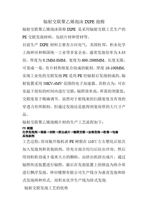
辐射交联聚乙烯泡沫IXPE泡棉辐射交联聚乙烯泡沫简称IXPE 是采用辐射交联工艺生产的PE交联发泡材料,包括片材和管材等。
目前生产IXPE材料主要有古河电气,美国杜邦,积水化学上海钟田和韩国统一工业等多家企业,通常发泡倍率为3-35倍,厚度为0.2MM-8MM,宽度为600-2000MM,长度无限,可卷成一卷,有片材热熔复合而成的板材,厚度10-100MM,实现工业化的交联发泡PE是用PE经辐射后发泡制成的,辐射装置采用50KV-4MV范围的电子加速器,其特点为:可在室温下很短的时间内进行交联;辐照效率高,所需的剂量低,交联度易于精确调节。
虽然对于射线束的扫描宽度及有效的穿透力有所限制,但通过发泡还是能得到宽而厚的大尺寸产品。
辐射交联聚乙烯泡棉片材的生产工艺流程如下:PE树脂化学发泡剂→混炼→切粒→挤出成片→辐照交联→加热发泡→收卷→包装其他助剂工艺过程:用双辊开炼机讲PE树脂在110℃左右塑化后依次加入发泡剂和其他助剂,待充分混合均匀后拉出冷却,然后用切粒机切成5毫米大小的颗粒,由挤出机挤出成片,通过辐照传送装置进行辐照,最后在发泡装置上的熔盐为热介质进行飘浮发泡。
钟田橡塑有限公司生产线分为垂直发泡和卧式发泡两种形式,而积水化学生产线为卧式发泡.辐射交联发泡工艺的优势同化学交联发泡工艺相比较,辐射交联发泡有如下优点。
1减少环境污染。
用辐射交联发泡工艺可以免去化学交联剂分解后产生的有害气体,无毒无味。
减少空气污染。
2过程易于控制。
辐射交联发泡工艺较化学交联发泡工艺过程易于控制,原材料如基础树脂或发泡剂选择更加容易。
3提高产品质量。
在化学交联工艺中交联剂通过加热在较宽温度范围进行分解,交联过程中难以保证产品的均匀性,且不能控制产品的交联度。
而辐射交联工艺是在同一温度下实现产品交联,因而质地均匀,并可控制产品交联度的大小。
4提供发泡速度。
辐射工艺可在任意温度下实现产品均匀交联,然后再进行发泡,因此发泡速度比化学交联工艺快1倍。
辐射或超临界二氧化碳法制备交联微孔发泡聚乙烯
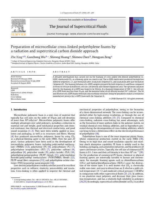
J.of Supercritical Fluids 47(2008)281–289Contents lists available at ScienceDirectThe Journal of SupercriticalFluidsj o u r n a l h o m e p a g e :w w w.e l s e v i e r.c o m /l o c a t e /s u p f luPreparation of microcellular cross-linked polyethylene foams by a radiation and supercritical carbon dioxide approachZhe Xing a ,b ,Guozhong Wu b ,∗,Shirong Huang a ,Shimou Chen b ,Hongyan Zeng aa College of Chemical Engineering,Xiangtan University,Xiangtan,Hunan 411105,ChinabShanghai Institute of Applied Physics,Chinese Academy of Sciences,Jialuo Road 2019,Jiading,Shanghai 201800,Chinaa r t i c l e i n f o Article history:Received 29February 2008Received in revised form 31July 2008Accepted 20August 2008Keywords:LDPESupercritical carbon dioxide Radiation Cross-linkingMicrocellular foama b s t r a c tA detailed investigation was carried out on the foaming of cross-linked low-density polyethylene (x-LDPE)sheets with CO 2as a blowing agent on a batch scale.The x-LDPE sheets were produced through two different sequences,i.e.,part formation after irradiation (Sequence A),and irradiation after part formation (Sequence B).The foaming behavior of x-LDPE samples prepared by both Sequence A andB was compared in terms of cell size distribution,cell size,cell density and volume expansion ratio.The optimum radiation dose for the foaming of x-LDPE was found to be 50kGy.At a foaming temperature of 100◦C,the cell size of x-LDPE foam was less than 10m,and the maximal value of cell density reached 1011cells/cm 3.The SA and SB series of x-LDPE foams both had a microcellular structure.It may be possible to realize a continuous manufacture process for x-LDPE foam with the Sequence A.©2008Elsevier B.V.All rights reserved.1.IntroductionMicrocellular polymeric foam is a new class of material that typically has cell sizes on the order of 10m and cell densities of more than 109cells/cm 3.Microcellular polymeric foams offer multiple advantages over solid polymers,including a reduction in material cost and weight,good mechanical properties and chem-ical resistance,low thermal and electrical conductivity,and good sound insulation [1–3].They have been widely applied in insu-lation and packaging,as well as in structures and filters.Martini [4]first produced microcellular polymeric foams by using CO 2as a physical-blowing agent in the early 1980s.Over the past 25years,various polymers have been used in the development of microcellular polymeric foams,including poly(methyl methacry-late)(PMMA)[3,5],polystyrene (PS)[6],polycarbonate (PC)[7],poly(ethylene terephthalate)(PET)[7],poly(ether sulfone)[8],polysulfone [8],poly(ether imide)[9],poly(l -lactide)(PLA)[10],polyethylene/polypropylene (PE/PP)blends [11],poly(vinylidene fluoride)/poly(methyl methacrylate)(PVDF/PMMA)blends [12],PE/PP-wood fiber composites [13],and polyethylene-octene elas-tomer (POE)/organoclay nanocomposite [14].Low-density polyethylene is widely used because of its excellent properties such as softness,elasticity,processibility and insula-tion.Cross-linking is often applied to improve the thermal and∗Corresponding author.Tel.:+862159554531;fax:+862159558905.E-mail address:wuguozhong@ (G.Wu).mechanical properties of polyethylene,owing to the formation of a three-dimensional network.The cross-linking can be accom-plished either by high-energy irradiation,or through the use of chemical cross-linking additives [15–17].Compared to chemical cross-linking,radiation cross-linking has some advantages,such as the formation of more uniform links in the polymer matrix,no residual chemical cross-linking additives,and no byproducts gen-erated during the decomposition of cross-linking additives,which can bring to bear a deleterious effect on the electrical performance of polyethylene [18].Polyethylene foam is one of the most important plastic foams,whose commercial production started in the early 1940s [19].Owing to its high heat and sound insulation capacity and excel-lent shock absorption capability,PE foam is widely used in the building,packaging,and automotive industries,and by producers of sports and leisure articles.Typically,the cell size of commercial PE foams is 0.1–1mm and their cell density is less than 106cm −3[20].For the production of commercial PE foams,chemical or physical foaming agents are universally harmful to human and environ-ment.For example,foaming agents such as chlorofluorocarbons (CFCs)and hydrochlorofluorocarbons (HCFCs)cause the destruc-tion of the ozone layer.It is well known that CO 2is chemically stable,non-toxic,and easy to obtain from air.It also has a mild crit-ical temperature (31◦C)and moderate critical pressure (7.38MPa)in comparison with other supercritical fluids [21–23].In addition,it can plasticize most polymers and decrease their glass transi-tion temperature,and has a relatively high solubility in polymers [24,25].Accordingly,supercritical carbon dioxide (scCO 2)is an ideal0896-8446/$–see front matter ©2008Elsevier B.V.All rights reserved.282Z.Xing et al./J.of Supercritical Fluids47(2008)281–289replacement of traditional foaming agents and has been increas-ingly employed in the polymeric microcellular forming process as a clean blowing agent.The effect of saturation pressure,foaming temperature and depressurization rate on the morphology of polyolefin foams has been extensively studied[26–32].The results show that higher sat-uration pressure leads to higher cell density and smaller cells,while higher foaming temperatures result in lower cell density and larger cells.It has also been found that a higher depressurization rate induces a higher number of cell nuclei.However,the study of foam-ing of irradiated PE with scCO2has seldom been reported.In our previous work,foaming of PMMA microspheres[33]and microp-orous PVDF membranes[34]was carried out by using scCO2.In this paper,we prepared cross-linked PE microcellular foam by a com-bination of radiation cross-linking and the scCO2foaming process. Two processing sequences were used to prepare radiation-cross-linked low-density polyethylene(x-LDPE)sheets:(1)irradiation followed by screw extrusion and hot pressing(Sequence A),and (2)hot pressing followed by irradiation(Sequence B).The specimen made by Sequence A is named SA and the one made by Sequence B is named SB.The Sequence A adopts the idea of radiation modification of PE pellets prior to part formation[35];therefore,it is an easy-to-accomplish extrusion foaming technology.The cell structures of SA and SB foams were compared in detail,and the effects of radiation dose on cell size(D),cell density(N f)and volume expansion ratio (R v)were also investigated.The samples produced by Sequence A can be expanded into microcellular foam and have higher volume expansion ratio than the ones made by Sequence B.The Sequence A provides a new way to prepare microcellular cross-linked LDPE foams.The mean diameter of cells of x-LDPE foams is less than 10m,and the value of cell densities of x-LDPE foams is more than 109cells/cm3when all x-LDPE samples were foamed at the foaming temperature of100◦C.The optimal radiation dose for the foaming of x-LDPE is found to be50kGy.Irradiation led to a wider foaming temperature range of LDPE.2.Experimental2.1.MaterialsLow-density polyethylene(LD100-AC,pellet)was purchased from Sinopec Beijing Yanshan Chemical Corporation,with a den-sity of0.9225g/cm3and melt index of2.0g/10min.Carbon dioxide (>99.5%pure)was from Loutang Special Gases of Shanghai.2.2.Irradiation of LDPEThe␥-irradiation was carried out in the60Co source of the Shanghai Institute of Applied Physics.Two processing sequences were used to prepare␥-ray irradiated LDPE(Fig.1).In thefirst sequence,PE pellets werefirst irradiated at different doses in sealed vessels at room temperature,and then mixed in the mixer(Thermo Haake PolyDrive,Germany)and hot pressed at160◦C and18MPa for8min into thin sheets in1mm thickness.The specimen made by this procedure is labeled sample of Sequence A(SA).In the second sequence,PE pellets were initially hot pressed into1mm thin sheets under the same conditions,and subsequently irradi-ated at different doses in sealed vessels at room temperature.The specimen processed by this procedure is denoted as sample of Sequence B(SB).The non-irradiated sheet is labeled sample S0.All specimens were cut into15mm×8mm pieces for the foaming pro-cess.The dose rate was1.09kGy h−1and irradiation doses were25 (SA25,SB25),50(SA50,SB50),75(SA75,SB75)and100kGy(SA100, SB100),respectively.2.3.Foaming processIn this study,the saturation pressure,soaking time and depres-surization rate were kept constant at22MPa,8h and0.7MPa/s, respectively.Five different temperatures(100,105,110,120,and 130◦C)were used as foaming temperatures(T f).The supercriti-cal experimental setup was schematically depicted in the previous paper[33].The foaming process consists of three stages:(1)sat-uration by CO2at the desired temperature and pressure;(2)cell nucleation and growth during the release of CO2pressure;and(3) cell stabilization in the cooling process associated with the CO2 depressurization.In thefirst stage,the specimens sealed into the high-pressure vessel were preheated to the desired temperature after air was expelled from the vessel by CO2gas.Subsequently, the CO2pressure was increased up to the desired pressure using a high-pressure liquid pump;simultaneously the temperature inside the autoclave was increased and maintained at a predetermined temperature using a band heater for temperature control.When the temperature was stable,the specimens were kept at the pre-determined pressure and temperature for8h.In this length of time,the sample was completely saturated by scCO2[36].In the second stage,in order to supersaturate the specimen with CO2, the autoclave was quickly depressurized to atmospheric pressure by opening a depressurization valve.The thermodynamic instabil-ity resulted in the formation of a large number of cell nuclei in the LDPE samples.The temperature inside the autoclave quickly decreased during the rapid depressurization.Eventually,the spec-imens were removed from the vessel and cooled to ambient temperature.2.4.Foam characterization2.4.1.Morphology of foamMicrostructures of the foamed LDPE samples were characterized by a LEO1530VP scanning electron microscope at an acceleration voltage of5.0kV.The samples were immersed in liquid nitrogen and fractured at liquid nitrogen temperatures,then mounted onstubs.Z.Xing et al./J.of Supercritical Fluids 47(2008)281–289283Fig.2.DSC curves of the melting transition of SA (a)and SB (b)series of LDPE samples at different doses.The fractured surfaces were sputter-coated with gold for observa-tion.The SEM photographs were analyzed by the software Image Pro.With this method,the cell density (N f )is determined by the number of cells per unit volume of foam,which was calculated using Eq.(1):N f =nM 2A3/2(1)where n ,M and A are the number of cells in the micrograph,the magnification of the micrograph,and the area of the micrograph (cm 2),respectively.The densities of solid and foamed specimens were determined by deducing the Archimedes Law involving weighing polymer foam in water with a sinker using an electronic analytical balance (HANG-PING FA2104),as described by Eq.(2):=a a +b −cw(2)where a ,b and c are the weight of the specimen in air without sinker,the totally immersed sinker and the specimen immersed in water with sinker,respectively,and w is the density of water.The volume expansion ratio (R v )is the ratio of the solid polymer density ( s )and the foam density ( f ),as given by Eq.(3):R v =s f(3)The average cell diameter (D )was calculated using Eq.(4):D = d i n in i(4)where n i is the number of cells with an area-equivalent diameter of d i .2.5.Melting point and crystallizationA Mettler Toledo DSC822e differential scanning calorimeter equipped with a data station was used for scanning the melting transitions of virgin and ␥-irradiated samples of about 5–10mg in aluminum pans.The samples were heated from 0◦C up to 150◦C at a heating rate of 10◦C/min under 50mL/min nitrogen flow.The degree of crystallization was calculated using Eq.(5):X c (%)=H fH f0×100(5)where H f is the melting enthalpy of LDPE and H f0is the specific melting enthalpy for 100%crystalline polyethylene,which has a 2.6.Gel contentThe gel content was determined using a 72h Soxhlet extraction cycle using xylene as the solvent.Approximately 1g of the irra-diated LDPE was placed in a pre-weighed stainless steel fine wire mesh.After extraction,the solid remainder was dried to a constant weight in a vacuum oven at 60◦C and then re-weighed.The gel fraction was sequentially obtained.3.Results and discussion 3.1.Effect of irradiation on LDPEFig.2shows DSC curves of melting transitions of virgin and irradiated LDPE specimens.It is shown that melting point of LDPE decreases slightly after irradiation.The melting point of LDPE is listed in Table 1.Since the melting point is an indication of the crystallite size and perfection,a decrease in the melting point implies smaller and/or less-perfect crystallites are being formed in polymer matrix after irradiation [38].The imperfec-tion in the polymeric chains caused by the irradiation restrains the crystallization process,leading to smaller and less-perfect crystallites.Fig.3(a)shows the effect of the radiation dose on the crys-talline content of the irradiated samples (SA and SB).The melting enthalpy of LDPE samples is listed in Table 1.The crystallinity of irradiated LDPE decreased slightly with an increase in the dose from 25to 100kGy.However,the crystallinity of LDPE samples SA25and SA50was higher than that of non-irradiated LDPE.This can be attributed to the mixing process of the irradiated LDPE pellet in the mixer at 160◦C.The frequency of motion and rearrangement of the macromolecular chain increases during the mixing process,which in turn may lead to regular arrange-ment of more macromolecular segments.Survival radicals in the irradiated polymer can react with oxygen to induce oxidative degradation during the mixing.In addition,scission and cross-linking of polyethylene chains can be simultaneously induced by ␥-irradiation.Oxidative scission prevails at low radiation dosesTable 1Melting point and enthalpy for SA and SB series of samples Radiation dose (kGy)SA series SB series T m (◦C)H f (J/g)T m (◦C) H f (J/g)0113.1148.9––25107.9161.2108.1144.350108.0153.9108.1141.375108.1145.9108.0141.0284Z.Xing et al./J.of Supercritical Fluids 47(2008)281–289Fig.3.(a)Crystallinity of irradiated LDPE samples.(b)Gel content of irradiated LDPE samples of SA.and cross-linking dominates at higher doses [39–41].The short chains derived from degradation crystallize at a higher degree,but produce smaller and less-perfect crystallites.The rearrangement of the macromolecular chains,and the degradation occurring at lower radiation doses,promoted the crystallization of the irradiated LDPE.Generally,the degree of polymer cross-linking can be estimated from gel fraction determination.Fig.3(b)shows thepercent-Z.Xing et al./J.of Supercritical Fluids47(2008)281–289285Fig.5.Effect of radiation dose on the cell morphology parameters of SA foams produced at100◦C:(a)cell size distribution,(b)average cell diameter(D)and cell density(N f).age of the gel formed in the LDPE matrix at various radiation doses.It can be clearly seen that the degree of cross-linking increased with increasing radiation dose over the range of values studied.3.2.Morphology of cross-linked LDPE foamsThe micrographs of specimens foamed at various temperatures were also investigated.A statistical calculation on cell size andsum286Z.Xing et al./J.of Supercritical Fluids 47(2008)281–289Fig.7.SEM micrographs for the SB series of LDPE foams produced at 105◦C and at different doses (kGy):(a)25;(b)50;(c)75;(d)100.of cells was performed using the SEM images.For a better compar-ison,the characterization of the non-irradiated specimen foamed under the same conditions is presented together with the irradiated LDPE.Fig.4shows the effect of radiation dose on the cell morphol-ogy of SA samples foamed at 100◦C.It can be observed that the cells were discrete,nearly spherical and surrounded by thick walls.Fig.5shows the cell morphology parameters of SA samples foamed at 100◦C,such as cell size distribution,average cell diameter and cell density.The width of the cell size distribution peak,which indi-cates the dispersity of the cell size,first decreased at 25kGy and then increased with increasing dose,and the widest width of the cell size distribution peak was found at 100kGy in Fig.5(a).It is indi-cated that the uniformity of cell size became poor at higher dose,which can be also clearly observed in the micrograph of the SA100foam (Fig.4(e)).The mean cell diameter was less than 10m and the minimum cell density was more than 109cm −3for all foaming samples in Fig.5(b).However,the dose-dependences of the aver-age cell diameter and cell density were not regular.This is because the cells grew up slowly at a lower foaming temperature due to the higher elastic modulus and stiffness of the LDPE.Consequently,the foaming behavior of irradiated LDPE cannot be clearly identified for the foaming at relatively low temperature,e.g.,100◦C.Fig.6shows typical SEM images of the fracture surfaces of the SA series of LDPE foams produced at 105◦C.It should be noted that homogeneous cells were formed and all foams had closed-cell structures.For the LDPE foams at 0and 25kGy,the walls of some cells contained wrinkles and small holes.Polygonal closed-cell structures were observed at 50kGy,while continuous spheres surrounded by thick walls were observed at 75and 100kGy.Fig.7shows SEM images of the fracture surface of the SB series of LDPE foams produced at 105◦C,in a similar manner as the SA series of foams shown in Fig.6.The uniformly closed-cell struc-foams retained continuous spheres surrounded by a thick wall and became smaller in contrast to those of the SA series of foams.Fig.8(a)and (c)shows the dose-dependence of cell size and size distribution.With an increase in radiation dose,the cell size and the width of cell size distribution peak changed significantly for the SA foaming samples,but only slightly for the SB series of foam-ing samples.The statistical results indicated that the morphology of the SA foams was different from that of the SB samples.For foaming under the same conditions,the SA series of foams had larger cell size and a wider dispersity of size distribution than the non-irradiated LDPE samples,whereas the cell size of the SB foams decreased slightly and the change in the dispersity of size distribution was insignificant.Fig.8(b)and (d)shows the dose-dependence of the foam struc-tural parameters.It is clearly seen that the dose-dependence of cell size and cell density were completely opposite for the SA and SB foams.The average cell diameter of the SA samples increased ini-tially and then decreased with increasing radiation dose,having a maximum value at 50kGy.To the contrary,the average cell size of the SB foams first decreased and then increased with increasing dose,having a minimum size at 50kGy.The dose-dependence of the cell density also has a similar pattern.The difference between the SA and SB methods in the dose-dependence of cell structure is ascribed to the difference in the processing of LDPE (Fig.1).For the SA samples,mixing after irradiation caused the transforma-tion of microstructure,e.g.,motion and rearrangement of molecular chains.Therefore,cross-linking networks were partly destroyed,and a separation of gel and sol phases probably took place in the matrix of the SA samples [42–46].The influence of hot mixing on the phase variation in LDPE was more significant at 50kGy than at lower or higher doses,because gel and sol fractions are almost equal at this dose.For the SB samples,the cross-linking sites generated by irradiation were uniformly distributed in theZ.Xing et al./J.of Supercritical Fluids47(2008)281–289287Fig.8.Effect of radiation dose on the cell morphology parameters of irradiation-cross-linked LDPE foams produced at105◦C:(a)cell size distribution of the SA foams,(b) average cell diameter(D)and cell density(N f)of the SA foams,(c)cell size distribution of the SB foams,(d)average cell diameter(D)and cell density(N f)of the SB foams.Fig.9shows the variation of volume expansion ratio(R v)of the SA and SB series of foams as a function of dose for foaming tem-peratures of100,105,110,120and130◦C,respectively.Our results show that the R v of these series of foams generally increased with temperature,and that the R v of SA foams was higher than that of SB foams.The R v increased initially,and then decreased as radi-ation dose increased.The maximum R v was observed at50kGy, implying an optimum radiation dose of50kGy for the foaming of LDPE.The change in R v is attributed to the effect of radiation on the chain structure of LDPE.It is known that radiation causes structural changes in LDPE,including cross-linking,degradation, unsaturation,branching and oxidation[39,41].Cross-linking and branching enhance the chain entanglement and interaction among macromolecules,resulting in higher melt strength and viscosity.In contrast,degradation and oxidative scission lead to a decrease of macromolecular chain length,resulting in lower melt strength and viscosity[30,35].The oxidative scission mechanism occurs mainly at low radiation dose,while the cross-linking prevails at higher dose[39,41,47].The melt strength of LDPE irradiated at25kGy was weak in comparison with LDPE irradiated at a higher dose.There-fore,the cell wall was breached easily,and cells collapsed at the dose of25kGy.However,the melt strength of cross-linking LDPE irradiated at100kGy became so strong that the development of cell nuclei was restrained,leading to a decrease in cell density and the R v of LDPE foam.As a result,lower or higher doses led to a lower R v of the foam,and cells grew well only at moderate radia-tion dose,e.g.,50kGy.In addition,the volume of the SA series of foams was larger than that of the SB samples after expansion at the same foaming conditions,indicating that foaming of the SA sample was easier than that of the SB sample under the same conditions.Fig.10shows the micrographs of fracture surfaces of three spec-imens(S0,SA50and SB50)foamed at130◦C.As for S0,cells fusion and the breaking up of cell walls are shown clearly.This is due to the foaming temperature of130◦C being too high for the foamingof288Z.Xing et al./J.of Supercritical Fluids 47(2008)281–289Fig.10.SEM micrographs for three foaming specimens foamed at 130◦C (a)S 0,(b)SA50and (c)SB50.the original LDPE.Under this condition,the elasticity modulus and stiffness of LDPE are so weak that cells collapse during the depres-surization stage.In the case of SA and SB,the cells remained intact and displayed an impinging polygonal closed-cell structure.More-over,cells of the SA50foam inflated more than those of SB50,in good agreement with the measurement of R v .It has been demon-strated that irradiation treatment results in significant expansion of the foaming temperature range for LDPE due to the increase in melt strength and viscosity.4.ConclusionsWe have investigated the foaming behavior of two series of ␥-irradiated LDPE by using scCO 2as a blowing agent.The two series of samples revealed a reverse pattern of cell structure (cell size distribution,cell size and cell density)with increasing radia-tion dose.The SA series of specimens possessed a higher volume expansion ratio,greater cell size and lower cell density than the SB series of specimens at the same dose and foaming conditions.Irradiation led to a wider foaming temperature range of LDPE.The radiation dose of 50kGy is optimum for the foaming of LDPE.The experimental sequence of SA samples may be suitable for contin-ual industrial production of cross-linking PE foams by connecting a screw extruder to a scCO 2supply system.AcknowledgementThis work was supported by the “Hundred talents”project of the Chinese Academy of Sciences.References[1]D.I.Collias,D.G.Baird,R.J.M.Borggreve,Impact toughening of polycarbonate[2]L.M.Matuana,C.B.Park,J.J.Balatinecz,Structures and mechanical properties ofmicrocellular foamed polyvinyl chloride,Cell.Polym.17(1998)1–16.[3]S.K.Goel,E.J.Beckman,Generation of microcellular polymeric foams usingsupercritical carbon dioxide.I:Effect of pressure and temperature on nucle-ation,Polym.Eng.Sci.34(1994)1137–1147.[4]J.E.Martini,The production and analysis of microcellular foam,S.M.Thesis,Dept.Mech.Eng.,MIT,1981.[5]S.K.Goel,E.J.Beckman,Generation of microcellular polymeric foams usingsupercritical carbon dioxide.II:Cell growth and skin formation,Polym.Eng.Sci.34(1994)1148–1156.[6]K.A.Arora,A.J.Lesser,T.J.McCarthy,Compressive behavior of microcellularpolystyrene foams processed in supercritical carbon dioxide,Polym.Eng.Sci.38(1998)2055–2062.[7]M.T.Liang,C.M.Wang,Production of engineering plastics foams by supercriticalCO 2,Ind.Eng.Chem.Res.39(2000)4622–4626.[8]B.Krause,R.Mettinkhof,N.F.A.van der Vegt,M.Wessling,Microcellular foam-ing of amorphous high-T g polymers using carbon dioxide,Macromolecules 34(2001)874–884.[9]B.Krause,H.J.P.Sijbesma,P.Münüklü,N.F.A.van der Vegt,M.Wessling,Bicon-tinuous nanoporous polymers by carbon dioxide foaming,Macromolecules 34(2001)8792–8801.[10]Y.Ema,M.Ikeya,M.Okmoto,Foam processing and cellular structure ofpolylactide-based nanocomposites,Polymer 47(2006)5350–5359.[11]S.Doroudiani,C.B.Park,M.T.Kortschot,Effect of the crystallinity and morphol-ogy on the microcellular foam structure of semicrystalline polymers,Polym.Eng.Sci.36(1996)2645–2662.[12]S.Siripurapu,Y.J.Gay,J.R.Royer,J.M.DeSimone,R.J.Spontak,S.A.Khan,Gener-ation of microcellular foams of PVDF and its blends using supercritical carbon dioxide in a continuous process,Polymer 43(2002)5511–5520.[13]Y.W.Chang,D.Lee,S.Y.Bae,Preparation of polyethylene-octene elastomer/claynanocomposite and microcellular foam processed in supercritical carbon diox-ide,Polym.Int.55(2006)184–189.[14]O.Faruk,A.K.Bledzki,L.M.Matuana,Microcellular foamed wood-plastic com-posites by different processes:a review,Macromol.Mater.Eng.292(2007)113–127.[15]J.V.Gulmine,L.Akcelrud,Correlations between the processing variables andmorphology of crosslinked polyethylene,J.Appl.Polym.Sci.94(2004)222–230.[16]H.A.Khonakdar,S.H.Jafari,U.Wagenknecht,D.Jehnichen,Effect of electron-irradiation on cross-link density and crystalline structure of low-and high-density polyethylene,Radiat.Phys.Chem.75(2006)78–86.[17]S.P.Hlangothi,I.Krupa,V.Djokovic,A.S.Luyt,Thermal and mechanical prop-erties of cross-linked and uncross-linked linear low-density polyethylene–wax blends,Polym.Degrad.Stabil.79(2003)53–59.[18]H.Wagner,J.Wartusch,About the significance of peroxide decomposition prod-Z.Xing et al./J.of Supercritical Fluids47(2008)281–289289[19]Y.Zhang,D.Rodrigue,A.K.Abdellatif,High-density polyethylene foams.I:Poly-mer and foam characterization,J.Appl.Polym.Sci.90(2003)2111–2119. [20]J.M.Williams,D.A.Wrobleski,Microstructures and properties of some micro-cellular foams,J.Mater.Sci.24(1989)4062–4067.[21]A.I.Cooper,Recent developments in materials synthesis and processing usingsupercritical CO2,Adv.Mater.13(2001)1111–1114.[22]J.L.Kendall,D.A.Canelas,J.L.Young,J.M.DeSimone,Polymerizations in super-critical carbon dioxide,Chem.Rev.99(1999)543–564.[23]J.Liu,B.Han,G.Li,Z.Liu,J.He,G.Yang,Solubility of the non-ionic surfactanttetraethylene glycol n-laurel ether in supercritical CO2with n-pentanol,Fluid Phase Equilib.187(2001)247–254.[24]S.P.Nalawade,F.Picchioni,L.P.B.M.Janssen,Supercritical carbon dioxide as agreen solvent for processing polymer melts:processing aspects and applica-tions,Prog.Polym.Sci.31(2006)19–43.[25]A.I.Cooper,Porous materials and supercriticalfluids,Adv.Mater.15(2003)1049–1059.[26]K.Song,R.E.Apfel,Foaming of low-density polyethylene in a dynamic decom-pression and cooling process,Polym.Eng.Sci.41(2001)735–742.[27]O.Almanza,M.A.Rodríguez-Pérez,J.A.de Saja,The microstructure of polyethy-lene foams produced by a nitrogen solution process,Polymer42(2001) 7117–7129.[28]K.A.Arora, A.J.Lesser,T.J.McCarthy,Preparation and characterization ofmicrocellular polystyrene foams processed in supercritical carbon dioxide, Macromolecules31(1998)4614–4620.[29]K.Taki,T.Yanagimoto,E.Funami,M.Okamoto,M.Ohshima,E.Funami,Visualobservation of CO2foaming of polypropylene-clay nanocomposites,Polym.Eng.Sci.44(2004)1004–1011.[30]P.Zhang,N.Q.Zhou,Q.F.Wu,Y.Wang,X.F.Peng,Microcellular foaming of PE/PPblends,J.Appl.Polym.Sci.104(2007)4149–4159.[31]E.Reverchon,S.Cardea,Production of controlled polymeric foams by supercrit-ical CO2,J.Supercrit.Fluids40(2007)144–152.[32]S.Doroudiani,M.T.Kortschot,Polystyrene foams.I:Processing–structure rela-tionships,J.Appl.Polym.Sci.90(2003)1412–1420.[33]S.Huang,G.Wu,S.Chen,Preparation of open cellular PMMA microspheres bysupercritical carbon dioxide foaming,J.Supercrit.Fluids40(2007)323–329.[34]S.Huang,G.Wu,S.Chen,Preparation of microporous poly(vinylidenefluoride)membranes via phase inversion in supercritical CO2,J.Membr.Sci.293(2007) 100–110.[35]S.Cheng,F.Dehaye,C.Bailly,J.J.Biebuyck,R.Legras,L.Parks,Studies onpolyethylene pellets modified by low dose radiation prior to part formation, Nucl.Instrum.Methods Phys.Res.Sect.B-Beam Interact.Mater.Atoms236 (2005)130–136.[36]Z.M.Xu,X.L.Jiang,T.Liu,G.H.Hu,L.Zhao,Z.N.Zhu,W.K.Yuan,Foaming ofpolypropylene with supercritical carbon dioxide,J.Supercrit.Fluids41(2007) 299–310.[37]B.Wunderlich,C.M.Cormier,Heat of fusion of polyethylene,J.Polym.Sci.PartA-25(1967)987–988.[38]Y.Badr,Z.I.Ali,A.H.Zahran,R.M.Khafagy,Characterization of gamma irradi-ated polyethylenefilms by DSC and X-ray diffraction techniques,Polym.Int.49 (2000)1555–1560.[39]F.Vilaplana,M.E.Vanesa,H.N.Pilar,B.Monrabal,R.G.Amparo,Performanceof crystallization analysis fractionation and preparative fractionation on the characterization of␥-irradiated low-density polyethylene,J.Appl.Polym.Sci.94(2004)1803–1814.[40]G.Wu,Y.Katsumura,H.Kudoh,Y.Morita,T.Seguchi,Temperature dependenceof radiation effects in polyethylene:cross-linking and gas evolution,J.Polym.Sci.Part A:Polym.Chem.37(1999)1541–1548.[41]H.M.Abou Zeid,Z.I.Ali,T.M.A.Maksoud,R.M.Khafagy,Structure–propertybehavior of polyethylene exposed to different types of radiation,J.Appl.Polym.Sci.75(2000)179–200.[42]A.A.Gurtovenko, A.Blumen,Generalized Gaussian structures:models forpolymer systems with complex topologies,Adv.Polym.Sci.182(2005) 171–282.[43]R.J.J.Williams, B.A.Rozenberg,J.P.Pascault,Reaction-induced phase sep-aration in modified thermosetting polymers,Adv.Polym.Sci.128(1997) 95–156.[44]A.Izuka,H.H.Winter,T.Hashimoto,Self-similar relaxation behavior at thegel point of a blend of a cross-linking poly(epsilon-caprolactone)diol with a poly(styrene-co-acrylonitrile),Macromolecules30(1997)6158–6165.[45]Y.Ishii,A.J.Ryan,Processing of poly(2,6-dimethyl-1,4-phenylene ether)withepoxy resin.2:Gelation mechanism,Macromolecules33(2000)167–176. [46]K.C.Teng, F.C.Chang,Single-phase and multiple-phase thermoplastic/thermoset polyblends.1:Kinetics and mechanisms of phenoxy/epoxy blends, Polymer34(1993)4291–4299.[47]M.Nikolova,M.Mateev,Irradiation of oriented LDPEfilms,J.Appl.Polym.Sci.43(1991)201–204.。
PE发泡棉

东莞市宏恩塑胶制品有限公司XPE架桥发泡棉(聚乙烯交联)简介XPE(聚乙烯交联)又称架桥发泡棉,是一种新型环保材料,无毒、无味、隔音、吸音、隔热、焚烧时对大气无污染,回弹力好,可随意调整软硬度和厚度,重量轻等特点,是其他发泡棉类材料无可取代的,可热压成型,也可生产阻燃型,适用于运动护具、手袋箱包、汽车、航空航天、建筑、鞋材、玩具、空调、石油管道保温等。
产品特性XPE的相关特性:绝热性--其细微的独立气泡结构,可有效降低空气对流导致的能量交换,适合制作保温管、保温板。
并且兼具防结露性,使之极适合用于冰箱、空调及冷库等多湿环境的保温材料。
吸音性--具有吸音降噪功能,适合用于飞机、铁路车辆、汽车、电动机等强噪音设备及环境中的吸音隔音材料。
成型性--耐热性强,延展性能好,密度均匀,可实现真空成型及热成型等较深部位的成型,因而可用于汽车空调蒸发柜、汽车热压顶棚等内饰件及鞋材方面的材料。
缓冲性—材质为半硬质发泡体,受强冲击后也不失原性能,多用于精密仪器,半导体包装等领域,同时也可利用其易成型性,而用于体育防护用品及休闲用品的制作领域。
此外,XPE还具有无毒、无味、耐药品性、耐油、耐酸、耐卤及其他各类化学药品的性能,并且非常容易加工,可以任意裁切,与多种材料贴合,作为新一代高效节能、环保的材料必将会有广阔的发展前景。
XPE与其它同类产品的区别和优势:XPE比PEF产品具有优良的特性,如发泡倍率高,密度低,厚度薄,表面光滑,高弹性,高韧性,易于二次加工性。
XPE产品被世界上先进国家称为无公害产品,产品生产过程中,不造成环境污染,产品在使用后,易于回收,焚烧时不造成严重大气污染。
EPS、PU产品易风化,不易回收,焚烧时造成严重大气污染,因此在世界上先进国家逐步禁止EPS、PU作包装物进口,即必须采用XPE或EPE、EPP作包装的产品才允许进口。
用途:A)各种运动器具:如头盔,护具,冲浪板,滑雪靴,溜冰鞋,地垫,登山包,运动包。
EPP---TPU----TPO材料介绍.

一、EPP材料介绍:密度:20、30、45、60(单位g/l)原料种类:A. 普通料B. 抗静电料C.阻燃料加工方式:A. 模具成型B. 裁切成型C. 刀模冲击成型D. 黏贴成型( 热融胶. 强力胶. 热贴合) 环保回收方式:A. 融解( 分解再生为塑胶) B. 再生应用范围:防震(保护)包装、空调行业、电子行业、汽车、体育用品、建筑等等本产品特征:聚丙烯发泡材料是一种性能卓越的高结晶型聚合物/气体复合材料,以其独特而优越的性能成为目前增长最快的环保新型抗压缓冲隔热材料。
EPP制品具有十分优异的抗震吸能性能、形变后回复率高、很好的耐热性、耐化学品、耐油性和隔热性,另外,其质量轻,可大幅度减轻物品重量。
EPP还是一种环保材料,不仅可回收再利用,而且可以自然降解,不会造成白色污染。
随着加工温度的升高,PP树脂熔体粘度急剧下降,发泡剂分解出来的气体难以保持在树脂中,气体的逸散会导致发泡难以控制;结晶时也会放出较多的热量,使熔体强度降低,发泡后气泡容易破坏,因而不易得到独立气泡率高的发泡体。
若能使PP树脂在发泡之前交联,使其熔体粘度随着温度升高而降低的速度变慢,从而在较宽的温度范围内具有适当的熔体黏度。
交联还可同时提高PP泡沫塑料的物理机械性能,交联发泡PP比未交联的发泡PP耐热温度提高30%~50%℃,抗蠕变性能提高100 倍,其拉伸强度、刚性、耐冲击强度也都大幅度提高,耐油、耐磨性也获得很大改善。
交联发泡PP技术可分为两步法和一步法:两步法是将PP、交联剂、发泡剂和其他助剂先进行共混挤出,然后再进行水浴或是辐射交联,最后升温制得发泡塑料。
一步法是将PP、交联剂、发泡剂和其他助剂进行共混挤出,在挤出的过程中直接进行适当的交联,并使发泡剂分解,生产出泡沫塑料。
但这种方法要求对挤出过程中的反应程度进行准确的控制,因此难度较大。
目前已有多家企业和研究机构正在研究或已经研究出交联发泡PP的生产工艺,这其中大多为两步法生产工艺,少数能够采用一步法连续挤出。
聚乙烯交联发泡材料XPE

聚乙烯交联发泡材料(XPE)是一种用途广泛、性价(_shi4 yi1 zhong3 yong4 tu2 guang3 fan4 _xing4 jia4)比高、安全环保、国际公认的新型保温隔热材料,现匝在中国、欧美和中东市场广泛应用。
该材料有以下特点:
1.环保性:由于该材料中所含主要气体为氮气,对人体无毒害、对大气无污染,是世界上公认的环保材料。
2.绝热性:该材料内部组织为闭孔结构,导热系数为0.03-0.04KCAL/M.H.℃。
3.防潮性:XPE泡沫既是隔热层又是防潮层,不吸水。
即使表面局部损伤,也不影响整体的隔热防潮作用。
4.稳定性:聚乙烯交联发泡材料的物理化学性能特别稳定,抗腐蚀、耐低温、抗老化性能优良,长期使用各项物化性能变化甚微。
5.品种较多:可根据用户要求利用不同配方做成阻燃、导电、高弹等不同用途的发泡材料。
6.美观性:具有良好的弹性、质地柔软、手感舒适,表面一般无需装饰,并有多种彩色可选择。
7.施工性:无需过多的辅助层,只需切割粘接就可快速施工,不会产生有毒气体和屑尘。
8.加工性:可根据用户要求通过相应的后续加工设备,把片材加工成不同厚度、不同形状、不同用途的终端产品。
9.用途广泛:主要应用在冷库、中央空调、管道设施、土木建筑、车辆船舶、航空航天等工程的保温隔热,医疗器械、运动器材、周密器具的包装,幼儿园地板墙面及体育场馆建设等方面。
化学交联聚乙烯发泡材(XPE)、电子交联聚乙烯发泡材(IXPE)、电子交联聚丙烯发泡材(IXPP)、聚酯型聚氨酯海绵(PU)等产品。
导电泡棉知识

导电型辐射交联聚乙烯发泡卷材(又称导电泡棉、导电泡沫塑料等)的主要特性为:具有良好的永久导电性,表面电阻为103 Ω~105Ω、104Ω~106Ω和107Ω~109Ω;不含任何腐蚀物质,对元器件及包装物无任何腐蚀;防潮、减震及隔音、隔热性能优良;耐热、耐温性能优良,在-40℃~80℃温度范围内产品品质不受影响;力学性能优良,产品使用寿命长;化学稳定性好,产品不分解,无异味,无脱皮、不掉屑等,耐腐蚀能力强;产品容重适宜并可根据要求调整,满足不同元器件的插、装要求;具备良好的二次加工(如刨、切、复合等)性能;卷材厚度为4~8mm,复合及刨切产品厚度为1~50mm,幅宽一般在1.3m以内,卷材长度一般为50~100m;可根据客户要求,加工不同规格品种的产品。
辐射交联聚乙烯发泡卷材是一种高科技产品,它具有细密的闭孔结构,光滑的外表,优良的回弹性,较高的力学强度,优异的隔热、防水性能,优良的耐老化性和耐化学腐蚀性,并可进行复合、粘接、切割等二次成型加工。
适当改进配方后还可赋予其阻燃性、导电性等。
在阻燃海绵上包裹导电布。
具有良好的表面导电性,长、宽、高(L、W、H、)可以任意选择。
可以很容易用胶粘带固定在需屏蔽器件上。
有不同的剖面形状、安装方法、UL等级及屏蔽效能的屏蔽材料可供选择。
特点表面阻抗≤0.08Ω,可发挥同金属般优异的保护性能。
芯材料使用PU泡棉,减化表面压力,复原力极佳。
因该垫圈为表面光滑且富柔软性导电纤维,故可适合于各种接着面的形状。
在安装于筐体等物体时,较一般的粘附贴纸更易粘着。
该垫圈为难燃烧的规格可安心使用。
用途可运用于OA机器,笔型电脑,电脑及周边设备,无线械具,医疗器具及其他电子类产品等之EMI,EMS之防治。
IXPE和XPE泡棉介绍
深圳市长园特发科技有限公司
IXPE泡棉与XPE泡棉的区别IXPE(Irradiation crosslinked polyethylene foam):辐射交联聚乙烯发泡片材,该产品是将聚乙烯或改性聚乙烯与各种填料挤出成型,经过电子加速器辐射交联,高温发泡制得高分子泡沫材料。
XPE(Chemical crosslinked polyethylene foam):化学交联聚乙烯发泡片材,该产品是将聚乙烯与各种填料混合后,加入化学交联剂和发泡剂,制成的高分子泡沫材料。
两者均为交联聚乙烯闭孔泡沫塑料,XPE的交联方式是采用化学交联剂进行交联,而IXPE的交联方式则是采用电子加速器进行辐射交联,因此IXPE泡棉的力学性能均优于XPE,同时表面光滑细腻,但其价格较贵,设备前期投入大,常应用于汽车、体育、高档包装行业;而XPE由于价格便宜,常应用于一般的包装、建筑、空调行业。
深圳长园特发科技有限公司。
XPE聚乙烯交联又称化学交联聚乙烯发泡材料IXPE
XPE(聚乙烯交联)又称化学交联聚乙烯发泡材料,IXPE(聚乙烯交联)又称电子交联聚乙烯发泡材料,是一种新型环保材料,无毒、无味、隔音、防水、隔热、保温,焚烧时对大气无污染,回弹力好,可随意调整软硬度和厚度,重量轻等特点,是其他发泡棉类材料无可取代的,可热压成型,也可生产阻燃型,适用于运动护具、手袋箱包、汽车、航空航天、建筑、鞋材、玩具、空调、石油管道保温等.发泡倍数:3--35倍;宽度:1200-2000MM宽以内厚度:单层3-15MM ,也可复合成50-100MM厚不等,并可表面压光加工处理;常用颜色:黑色、白色、灰色、彩色等。
XPE的相关特性:1,绝热性--其细微的独立气泡结构,可有效降低空气对流导致的能量交换,适合制作保温管、保温板。
并且兼具防结露性,使之极适合用于冰箱、空调及冷库等多湿环境的保温材料。
2,隔音性--具有隔音降噪功能,适合用于飞机、铁路车辆、汽车、电动机、噪音设备及环境中的隔音材料。
以及建筑楼层、楼板、地板、墙体等地方隔音减振。
3,成型性--耐热性强,延展性能好,密度均匀,可实现真空成型及热成型等较深部位的成型,因而可用于汽车空调蒸发柜、汽车热压顶棚、汽车通风管、汽车遮阳板等内饰件内衬及鞋材方面的材料。
4,缓冲性—材质为半硬质发泡体,受强冲击后也不失原性能,多用于精密仪器,半导体包装等领域,同时也可利用其易成型性,而用于体育防护用品及休闲用品的制作领域,如:爬行垫、体操垫、运动护具等。
XPE和IXPE的常用用途:A)各种运动器具:如头盔,护具,冲浪板,滑雪靴,溜冰鞋,地垫,登山包,运动包、浮水板等。
B)汽车内饰:如车顶蓬,车门内侧,仪表四周,车灯内垫片,车装音响。
汽车脚垫XPE等。
该泡棉具有良好的可塑性,再加上其隔热,隔音,柔软与缓冲的特性,是目前先进国家车辆内装饰首选材料。
C)日用品领域:文具,工具,医疗器械,化妆品的外包装和照相机音响的保护材料。
也可用做箱包的内衬材料和家电,精密仪器,贵重物品等的防震包装和内衬材料。
永久导电辐射交联聚烯烃泡沫塑料的开发与研究
・
第4 3卷第 3期
2 0 1 5年 3月
l 3 6・
CHI NA PLAS TI CS I NDUS TRY
永 久 导 电辐 射 交 联 聚烯 烃 泡沫 塑 料 的开 发 与研 究
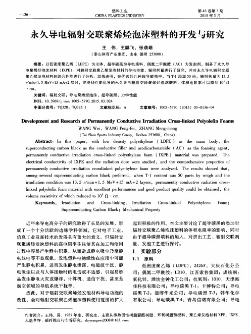
王 伟 ,王鹏 飞 ,张 萌萌
( 泰 山体 育产业集 团 ,山东 德州 2 5 3 6 0 0 ) 摘要 :以低密度聚 乙烯 ( L D P E )为主体 ,超导碳黑为导 电填料 ,偶氮二 甲酰胺 ( A C ) 为发泡剂 ,制 备了永久 导 电聚烯烃泡沫材料 ( I X P E ) 。对辐 射交联 聚乙烯发泡材料的导电性能 、辐照剂量进 行 了研究 ,并 对永久导 电辐射交联
聚 乙烯 发 泡 材 料 的综 种 超 导 碳 黑 中 ,当 T . 1添 加 5 0份 ,辐 照 剂 量 为 1 3 . 5
r / m i n + 1 . 5 Me V + 1 5 m A+ 2层时 ,能得到性能 优异 的永 久导 电辐射 交联 聚烯烃 泡沫 塑料 ,体 积 电阻率可 以降到 1 0 Q
‘ cm 。
关 键 词 :辐 射 交 联 ;导 电 聚烯 烃 泡 沫 ;超 导碳 黑 ;力 学 性 能
DO I :1 0 . 3 9 6 9 / j . i s s n . 1 0 0 5 - 5 7 7 0 . 2 0 1 5 . 0 3 . 0 2 4
中 图 分 类 号 :T Q 3 2 8 ;T Q 3 2 5 . 1
文 献 标 识 码 :A
文章 编 号 :1 0 0 5 — 5 7 7 0( 2 0 1 5 )0 3 — 0 1 3 6 — 0 4
De v e l o p me n t a nd Re s e a r c h o f P e r ma n e n t l y Co n d u c iv t e I r r a d i a i t o n Cr o s s - l i n ke d Po l y o l e i f n Fo a ms
聚乙烯辐射交联发泡

聚乙烯辐射交联发泡聚乙烯泡沫塑料继承了原材料聚乙烯树脂的所有优点:强韧、有挠性、耐摩擦、有优异的绝缘、隔热性和耐化学性,还具有飘浮性和缓冲性。
PE泡沫多为闲孔,无毒,有优良的二次加工性能,可以进行切削切断,可热成型、真空成型、压花成型,还可与其他材料复合。
PE泡沫分为交联和无交联两种,交联又分为化学交联和辐射交联。
化学交联PE最早由美国于1941年研制成功,其生产方法是非连续的。
辐射交联PE泡沫由日本于1965 年首先实现工业化,其他从事PE 辐射交联泡沫生产的主要厂家有美国V oltex,德国的Basf及英国的发泡橡胶和塑料公司,而我国在这方面几乎属于空白。
本文将主要就聚乙烯辐射交联发泡的机理和工艺,交联剂的种类,交联方式等展开综述。
1.辐射交联的优点化学交联和辐射交联的泡沫塑料之间的差别主要在于由辐射交联得到的泡孔质量更好一些。
由于生产过程中辐射交联先于发泡所以辐射交联法对于发泡板材的厚度有一定的要求,通常以薄型发泡制品为主。
另外,过量的辐射也会导致泡孔破裂并得到高密度制品。
而化学交联体系,交联同时在片材的中间和两面发生交联,所以对发泡板的厚度无限制[3]。
化学交联需要在高温下进行,而辐射交联在常温常压下就可以完成,辐射反应便于精确控制,重现性好,均匀性优于化学交联。
如,辐射交联产品用于电线电缆时,质量好,绝缘层交联均匀性佳,无烧结,无气泡,绝缘层不粘导体,易剥离,消除了由于熔融造成的偏心和变色。
另外,经过技术经济比较,辐射交联比化学交联应用范围广,生产效率高,成本低,创效大,节能节材[5]。
因此,PE泡沫塑料的辐射交联正在被广泛的应用和研究着。
2. 聚乙烯辐射交联发泡交联机理高分子辐射交联技术就是利用高能或电离辐射引发聚合物电离与激发,从而产生一些次级反应,进一步引起化学反应,实现高分子间交联网络的行成,是聚合物改性制备新型材料的有效手段之一。
高聚物的辐射交联是一个伴随着交联和主链降解的过程。
- 1、下载文档前请自行甄别文档内容的完整性,平台不提供额外的编辑、内容补充、找答案等附加服务。
- 2、"仅部分预览"的文档,不可在线预览部分如存在完整性等问题,可反馈申请退款(可完整预览的文档不适用该条件!)。
- 3、如文档侵犯您的权益,请联系客服反馈,我们会尽快为您处理(人工客服工作时间:9:00-18:30)。
聚乙烯辐射交联发泡
聚乙烯泡沫塑料继承了原材料聚乙烯树脂的所有优点:强韧、有挠性、耐摩擦、有优异的绝缘、隔热性和耐化学性,还具有飘浮性和缓冲性。
PE泡沫多为闲孔,无毒,有优良的二次加工性能,可以进行切削切断,可热成型、真空成型、压花成型,还可与其他材料复合。
PE泡沫分为交联和无交联两种,交联又分为化学交联和辐射交联。
化学交联PE最早由美国于1941年研制成功,其生产方法是非连续的。
辐射交联PE泡沫由日本于1965 年首先实现工业化,其他从事PE 辐射交联泡沫生产的主要厂家有美国V oltex,德国的Basf及英国的发泡橡胶和塑料公司,而我国在这方面几乎属于空白。
本文将主要就聚乙烯辐射交联发泡的机理和工艺,交联剂的种类,交联方式等展开综述。
1.辐射交联的优点
化学交联和辐射交联的泡沫塑料之间的差别主要在于由辐射交联得到的泡孔质量更好一些。
由于生产过程中辐射交联先于发泡所以辐射交联法对于发泡板材的厚度有一定的要求,通常以薄型发泡制品为主。
另外,过量的辐射也会导致泡孔破裂并得到高密度制品。
而化学交联体系,交联同时在片材的中间和两面发生交联,所以对发泡板的厚度无限制[3]。
化学交联需要在高温下进行,而辐射交联在常温常压下就可以完成,辐射反应便于精确控制,重现性好,均匀性优于化学交联。
如,辐射交联产品用于电线电缆时,质量好,绝缘层交联均匀性佳,无烧结,无气泡,绝缘层不粘导体,易剥离,消除了由于熔融造成的偏心和变色。
另外,经过技术经济比较,辐射交联比化学交联应用范围广,生产效率高,成本低,创效大,节能节材[5]。
因此,PE泡沫塑料的辐射交联正在被广泛的应用和研究着。
2. 聚乙烯辐射交联发泡交联机理
高分子辐射交联技术就是利用高能或电离辐射引发聚合物电离与激发,从而产生一些次级反应,进一步引起化学反应,实现高分子间交联网络的行成,是聚合物改性制备新型材料的有效手段之一。
高聚物的辐射交联是一个伴随着交联和主链降解的过程。
它的基本原理为:聚合物大分子在高能或放射性同位素作用下发生电离和激发,生成大分子游离基,进行自由基反应;并产生一些次级反应。
其反应终止机理大致如下[5]:
(1)辐射产生的邻近分子间脱氢,生成的两个自由基结合而交联
(2)产生的两个可移动的自由基相结合产生交联
(3)离子—分子反应直接导致交联
(4)自由基与双键反应而交联
(5)链裂解产生的自由基复合反应实现交联
(6)环化反应导致交联
3. 聚乙烯辐射发泡的工艺
辐射交联的工艺流程为:
将聚乙烯和发泡剂以低于发泡剂分解温度的温度混炼并成型为初坯,接着以剂量1~200kGY的射线辐射,使之交联,然后再加热到发泡剂的分解温度以上,是发泡剂分解放气,就制成了泡沫塑料制品。
PE发泡成型可以采用的化学发泡剂比较多,如偶氮二甲酰胺(AC),偶氮二甲酸二异丙酯,对甲苯磺酰氨基脲等。
[3]
对于PE泡沫来说,AC是较理想的发泡剂。
研究表明,AC的分解温度很高,约200°C左右,远高于聚乙烯的熔点,发气量大,无毒。
氧化锌、硬酯酸锌是促进AC分解的首选助剂,可以使其有较大的发气量和较快的分解速率。
为了制备发泡率高,泡孔细小均匀致密的高质量聚乙烯泡沫塑料,要求AC发泡剂在聚乙烯树脂中分解温度要低,AC在聚乙烯中的分解速度要快,分解产生的气体量要大。
单纯AC在聚乙烯树脂中的分解温度范围较宽,而含复合助剂的AC在聚乙烯树脂中的分解温度范围较窄。
聚乙烯一般常采用加交联剂的方法使PE熔体交联,以提高熔体的粘弹性,扩大熔体适宜发泡的温度区间。
交联剂的种类很多,但适宜作PE发泡成型交联剂的种类并不多,要求它不但与PE熔体有一定的相容性,而且它的分解温度必须比PE熔点高,比发泡剂的分解温度低,一般相互之间差10℃左右,这样使PE熔体在发泡剂分解之前,交联剂已经分解,并使熔体发生一定程度的交联,使PE熔体具有适宜发泡的粘弹性后,发泡剂再分解放出气体形成泡体。
[3]
交联发生在发泡以前,可使泡孔壁的表面张力加强,得到均匀致密的泡孔结构。
4.影响聚乙烯辐射交联的一些因素
4.1敏化作用
在聚合物中添加敏化剂,可以使反应速度加快,辐射交联的敏化及降解保护可以提高材料的使用性能,扩大其应用范围。
如吸入10%S2Cl2的PE薄膜,不但辐射剂量降低到原来的千分之一,强度也有所提高;PE中加入AMA,CB等,可使辐照剂量降低1/10到1/100。
在敏化剂蒸汽或溶剂中浸泡,或在聚合物加工成型以前,向其中掺入少量敏化剂,混合均匀后成型,然后进行交联化处理的方法已经得到了广泛的应用。
4.2辐照剂量
在辐射交联工艺中,因为是先交联后发泡,所以对发泡工艺而言,好的交联度很重要,交联度常用凝胶分数表示。
4.3辐照条件
辐照条件,如温度、压力、环境等对交联效率有一定的影响。
提高温度和全面加压,可以增加交联型高分子的交联度。
在真空或者惰性气体中辐照可以减少氧化降解,提高交联效率。
空气中的氧对PE尼龙的交联有一定的阻碍作用。
4.4发泡剂的分数和发泡温度对发泡倍率的影响
研究表明,在辐照剂量一定的情况下,随着发泡剂用量的增加,发泡倍率也增加,这是因为随着发泡剂用量的增加,在发泡过程中放出气体的体积增加,由于发泡粘度适宜,这些气体能均匀的分散其中,是发泡倍率增加。
发泡倍率还随着温度的增加而增大。
5.PE泡沫塑料的应用[5]
(1)包装领域
PE泡沫有良好的缓冲性,能防震防碎,常用于包装精密仪器和光学仪器,如照相机、电视机、计算机、玻璃器皿等
(2)建筑工程领域
在建筑冷藏库、位于寒冷地带的住房、厂房中的应用,能维持室内温度。
还可以用于育苗、蔬菜等的暖棚上,结实、保温、耐侯性好。
(3)交通运输领域
常利用PE泡沫的隔热保温性制造冷藏汽车、冷藏火车的车门和车衬里以及汽车线束管。
利用其耐化学性能好,能包裹腐蚀环境中的管道,辐射交联PE高发泡管材还可以用于管道的隔热保温,和空调机的保温管上和下水管的保温。