三相同步发电机的电压向量图原文
三相电压的相量表示
三相电压的相量表示是将时间上连续变化的三相正弦交流电压以复数形式表达,这种方法可以直观地描述各相电压在幅值、频率以及相位上的关系。
在电力系统分析中,通常采用极坐标或直角坐标(也称作笛卡尔坐标)来表示。
极坐标表示:
对于星形连接(Y接法)的三相电源或负载,其相电压相对于同一基准(例如A相)的相量表示为:
- A相:UA = V∠0°
- B相:UB = V∠-120°
- C相:UC = V∠120°
这里的V代表每相的有效电压幅值,角度表示的是相对于A 相的相位差,按照逆时针方向,B相滞后A相120度,C相超前A相120度。
直角坐标表示:
在静止对称坐标系(如αβγ坐标系或dq0坐标系)中,也可以转换成直角坐标形式表示,但此处不涉及具体的坐标变换过程。
对于三角形连接(Δ接法)的三相电压,线电压与相电压之间的关系如下:
- 线电压UAB = UA - UB = 380∠30° (假设有效线电压为380V)
- 线电压UBC = UB - UC = 380∠-90°
- 线电压UCA = UC - UA = 380∠150°
相量图中,三个电压相量按照120度均匀分布,且同时绕着同一个轴以相同的角速度逆时针旋转,这个角速度对应的就是系统的角频率ω(对于50Hz的交流电,ω=2π×50 rad/s)。
通过相量图和相量计算,能够简化复杂电路的分析和计算。
同步发电机电压方程相量图功率方程特性
电机学
1
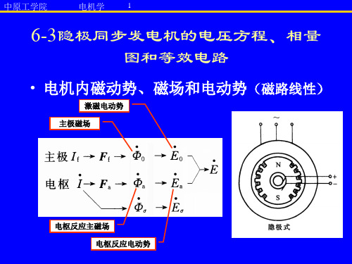
6-3隐极同步发电机的电压方程、相量
图和等效电路
• 电机内磁动势、磁场和电动势(磁路线性) 电机内磁动势、 磁路线性)
激磁电动势 主极磁场
电枢反应主磁场 电枢反应电动势
中原工学院
电机学
2
电路方程
• 初级电路 一相 初级电路(一相 一相) • 初级方程 • 激磁电动势大小
– 空载特性
中原工学院
电机学
7
凸极同步发电机分析方法
• 把电枢磁动势分解为: 把电枢磁动势分解为:
– 直轴磁动势
• 产生直轴磁场
– 交轴磁动势 交轴磁动势.
• 产生交轴磁场
• 可行分析
– 直轴的磁路随转子同步旋转,相对固定, 直轴的磁路随转子同步旋转,相对固定, 磁阻不变; 磁阻不变; – 交轴的磁路也随转子同步旋转,相对固定, 交轴的磁路也随转子同步旋转,相对固定, 磁阻不变。 磁阻不变。
• 运行特性:外特性,调整 外特性,
特性, 特性,效率特性
• 外特性
– n=同步转速,If和cosφ不 同步转速, 同步转速 不 变时, 变时,发电机端电压和电 枢电流之间的关系U=f(I) 枢电流之间的关系
• 电压调整率
中原工学院
电机学
23
6-7同步发电机的运行特性
• 调整特性 调整特性:
– n=同步转速,端电压=额 同步转速,端电压 额 同步转速 定电压, 定电压,cosφ=常数时的励 常数时的励 磁电流和电枢电流之间关 系,If=f(I)
中原工学院
电机学
10
直轴电枢反应电抗和 交轴电枢反应电抗
• 不计铁耗时,Ead滞后 d90o,Eaq滞后 q90o 不计铁耗时, 滞后I 滞后I
对称负载下三相同步发电机的电压向量图翻译教程文件

文章出处: R. H. Park, Electric Machinery, John Wiley, New York,2006对称负载下三相同步发电机的电压向量图电压向量图对分析同步电机的运行状况有着非常重要的作用。
从电压向量图上,我们可以得到同步电机电压变化率,即由于负载减小电压的升高和发电机从空载到负载过程中电压的下降等。
这些问题的解决具有重要意义:(1)在最初设计时要确定在不同的运行条件下所需的励磁电流;(2)在对已造好的电机进行测试时,判定其性能是否与原技术设计书中一致。
有了电压向量图,也使我们不必实际地施加负载,就能确定电机的运行状态。
当电机的容量较大时,要实际地施加负载是特别困难的。
电压向量图可以使我们能够通过计算机得到电机的主要运行特性。
最后,用电压向量图可以确定由励磁磁场产生的电势与端电压之间的功率角θ。
θ角无论在稳态还是在瞬态情况下,在分析电机产生的转矩和功率时起着重要作用。
由励磁磁通产生的电势E0’和同步电机端电压V’之间的向量差,取决于电枢反应的影响和电枢绕组的电阻和漏感抗上的电压降。
由于电枢反应的影响与电机的类型(凸极机还是隐极机),负载的性质(感性、电阻性还是电容性)和负载的平衡度(对称的还是不对称的)有很大关系,因此在画电压向量图时,所有这些因素都必须充分考虑到。
需要牢记的是,电压向量图中所有的电势和电压向量都是基波频率,因此所有的电势和电压都必须事先进行谐波分析,然后从这些谐波中将基波分离出来。
在讨论电枢反应的那一章中,已经分析了可以获得由与电机转子同步的电枢磁场分量产生的基波电压。
当一台电机将要交付使用时,技术人员根据从空载和短路特性实验中获得的数据绘出其电压向量图。
端电压是以下各因素共同作用的结果:(a)基波磁极磁势产生磁通Ф0,进而感应基波电势E0;(b)正比于负载电流的纵轴分量I d(其相对电势E0呈纯感性)的纵轴电枢反应磁势F ad ;(c)正比于负载电流的纵轴的横轴分量I q(其相对电势E0呈纯电阻性)的横轴反应磁势F aq ;正比于负载电流的漏电势Eσa=xσa I ;(e)定子绕组的纯电阻性电压降Ir a。
电流、电压向量图
初入门级人员,如果要看懂继电保护中的一些向量图和序量图,我觉得首先要明白一下几点:
1.电网中正常或故障运行时的出现的电气物理量,正序电压,负序电压,零序电压;正序电流,负序电
流,零序电流。
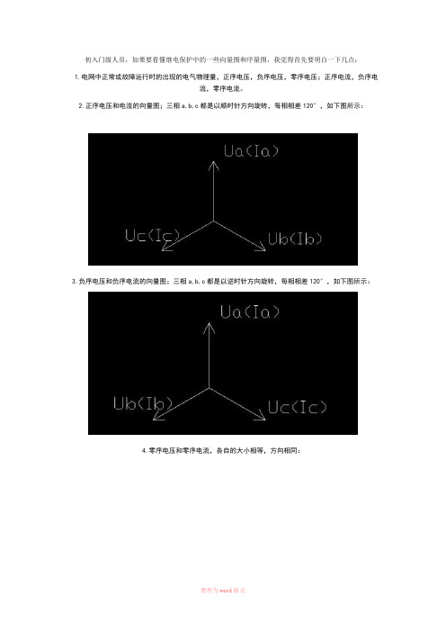
2.正序电压和电流的向量图;三相a,b,c都是以顺时针方向旋转,每相相差120°,如下图所示:
3.负序电压和负序电流的向量图;三相a,b,c都是以逆时针方向旋转,每相相差120°,如下图所示:
4.零序电压和零序电流,各自的大小相等,方向相同:
友情提示:本资料代表个人观点,如有帮助请下载,谢谢您的浏览!。
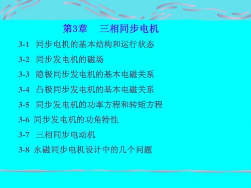
第3章三相同步电机
cos ϕ N
f N 单位为Hz n N单位为r/min θN
• 额定励磁电流和电压 IfN 、UfN
3-2 同步发电机的磁场
一、空载运行 n s If I=0
1、空载磁场——主磁场
I f → F f → B0 → φ 0
→ 电枢齿 路径:气隙 →电枢齿 → 电枢轭 → 磁极 主磁通 → 极身 → 转子轭 作用:在三相绕组中感应 对称电动势
k w1 N 1φ a k w1 N 1 Fa Λa (k w1 N 1 ) 2 kIΛa La = = = = = k (k w1 N 1 ) 2 Λa I I I I
ψa
二、考虑磁路饱和时 非线性,迭加原理不适用
Ff & & → F → B →Φ → E Fa
& U
& IRa
3、等效电路
& & & & & & & & E0 =U + I Ra + jIXσ + jIXa =U + I Ra + jIXs
4、同步电抗
X s = X a + Xσ
a) 反映了Φa和Φσ的作用 b) 磁路不饱和时为常数 c)
∝ f X a = ωLa ∝ (k w1 N 1 ) 2 ∝ Λ 主磁路的磁导 a
& 图示瞬间,A相绕组电动势 E0 A 达正的最大值,方向从X入,A 出。
•从导体切割磁力线分析。
(交轴)
• 从磁通的变化来分析。 A相磁通为零,电动势滞后磁 通90度。
& & B相绕组 E0 B、C相绕组电动势 E0 C 滞后A相电动势120度和240度。
三相功率相量图

说明:1. θ是施加在每一个功率测量元件上的电压与电流之间的电位差,滞后时为正。
2. 对于非真无功功率表,例如三(二)元件跨相90︒无功表、二元件人工中点(60︒)无功表等,进行分元件试验时,每个元件实际上是有功功率测量元件,而非无功功率测量元件,因而无法按照sinθ的设定值(1L、0.5L、0.5C、0等)进行试验,例如,当进行sinϕ=1的试验时,测量元件理应指示最大值,而实际上指零,因为它是有功测量元件。
所以应按有功功率分元件试验的方法进行,即用cosθ代替sinθ。
3. 对于非真无功功率表,有些用户习惯用表3所示的分元件试验方法,这也是一种有功功率分元件试验方法,只是对功率因数性质(感性或容性)的设定有所不同,使分元件试验时电压与电流之间的相位关系与无功表正常工作状态(合成)时的相位关系相同或相近,这种试验方法有明显的实用性,但导致功率因数性质颠倒,例如将θ = -60︒视为0.5L,将θ = 60︒视为0.5C,缺乏逻辑性。
4. 表2和表3所示分元件试验方法虽然不同,但都可评价每个元件的相位误差特性,因而都是有效的。
编写人:雷惠博2000.8.30功率电能四象限测量示意图说明:Array1.测量平面的竖轴为电压相量U,电流相量在四象限内变化,电流相量与电压相量之间的相位差为ϕ,沿顺时针方向(滞后)为正。
2.“ϕ”所在圆周内的标志值为ϕ;“sinϕ”所在圆周内的标志值为无功功率因数sinϕ;“cosϕ”所在圆周内的标志值为有功功率因数cosϕ。
3.对于无功功率电能测量,测量平面的Ⅰ象限为正感性(+L),Ⅱ象限为正容性(+C),Ⅲ象限为负感性(-L),Ⅳ象限为负容性(-C)。
4. 对于有功功率电能测量,测量平面的Ⅰ象限为正感性(+L),Ⅱ象限为负容性(-C),Ⅲ象限为负感性(-L),Ⅳ象限为正容性(+C)。
编写人:雷惠博2000.8.31。
第7章三相同步电机1(共46张PPT)
f1
p
n1 60
磁势和磁场是空间分布函数,磁通、
电势和电流是时间函数。由于只考虑
基波分量,因此,可以分别用空间矢
量和时间相量表示。又因为二者都有
相同的角速度,所以可以将二者画在
同一坐标平面图上,这种图称为
时空相量图,
图7-6同步电动机空载时的时空相量图
图中共四,十六+页A表示A相绕组的轴线。+j表示时间轴。
共四十六页
既然励磁磁势 和F f电枢磁势 均以Fa 同步(tóngbù)速旋转,两者相对 静止,因而可以相互叠加共同产生气隙磁势 。于是F,气隙磁势可 以表示为:
F Ff Fa
要解决的问题: 与F 的F相f 位和幅值关系。
电枢(diàn shū)反应与电枢F(adiàn shū)磁势F f 和主磁势 之间的空
共四十六页
7.3三相(sān xiānɡ)同步电动机的电势平衡方程 式、等值电路与相量图
对于三相(sān xiānɡ)同步电动机:
P N3 U N INcoNsN
共四十六页
7.2三相(sān xiānɡ)同步电动机的电枢反 应
7.2.1三相(sān xiānɡ)同步电动机空载时的磁场
空载:同步电机空载运行时,电枢电流基本为零。
若在转子绕组内通以直流励磁电流 ,I f则转子的直流 励磁磁势 (F f 或安匝数) 为F:f Nf I,f 称为励磁磁势,它产生 的磁场称为主磁场。 由励磁磁势 F建f 立主磁场并产生主磁通 和漏0 磁通 . 1
(a)按照电动机惯例规定各参量正方向
的电枢反应又称为交轴电枢反应。一般
用
来表示F。aq
(b) 空间矢量图
同步发电机的交轴电枢反应使得
第4章 三相电路

4.1 三相电源三相电源是具有三个频率相同、幅值相等但相位不同的电动势的电源,用三相电源供电的电路就称为三相电路。
1.对称三相电源在电力工业中,三相电路中的电源通常是三相发电机,由它可以获得三个频率相同、幅值相等、相位互差120°的电动势,这样的发电机称为对称三相电源。
图4.1是三相同步发电机的原理图。
三相发电机中转子上的励磁线圈MN 内通有直流电流,使转子成为一个电磁铁。
在定子内侧面、空间相隔120°的槽内装有三个完全相同的线圈A-X ,B-Y ,C-Z 。
转子与定子间磁场被设计成正弦分布。
当转子以角速度ω转动时,三个线圈中便 图4.1 三相同步发电机原理图 感应出频率相同、幅值相等、相位互差120°的三个电动势。
有这样的三个电动势的发电机便构成一对称三相电源。
对称三相电源的瞬时值表达式(以A u 为参考正弦量)为⎪⎪⎭⎪⎪⎬⎫+ω=-ω=ω=)120sin(2)120sin(2)sin(2 t U uc t U u t U u B A (4-1) 三相发电机中三个线圈的首端分别用A 、B 、C 表示;尾端分别用X 、Y 、Z 表示。
三相电压的参考方向为首端指向尾端。
对称三相电源的电路符号如图4.2所示。
它们的相量形式为⎪⎭⎪⎬⎫︒+=︒-=︒=120/120/0/U U U U U U CB A (4-2)对称三相电压的波形图和相量图如图4.3和图4.4所示。
对称三相电压三个电压的瞬时值之和为零,即0=++C B A u u u (4-3)图4.2 对称三相电源 图4.3 波形图三个电压的相量之和亦为零,即0=++C B A U U U(4-4)这是对称三相电源的重要特点。
通常三相发电机产生的都是对称三相电源。
本书今后若无特殊说明,提到的三相电源均为对称三相电源。
2.相序三相电源中每一相电压经过同一值(如正的最大值)的先后次序称为相序。
从图4.3可以看出,其三相电压到达最大值的次序依次为A u ,B u ,C u ,其相序为A -B -C -A ,称为顺序或正序。
同步发电机电压方程相量图功率方程特性25页文档
31、只有永远躺在泥坑里的人,才不会再掉进坑里。——黑格尔 32、希望的灯一旦熄灭,生活刹那间变成了一片黑暗。——普列姆昌德 33、希望是人生的乳母。——科策布 34、形成天才的决定因素应该是勤奋。——郭沫若 35、学到很多东西的诀窍,就是一下子不要学很多 特性
36、“不可能”这个字(法语是一个字 ),只 在愚人 的字典 中找得 到。--拿 破仑。 37、不要生气要争气,不要看破要突 破,不 要嫉妒 要欣赏 ,不要 托延要 积极, 不要心 动要行 动。 38、勤奋,机会,乐观是成功的三要 素。(注 意:传 统观念 认为勤 奋和机 会是成 功的要 素,但 是经过 统计学 和成功 人士的 分析得 出,乐 观是成 功的第 三要素 。
12种三相变压器联结组别及向量图详细说明

12种三相变压器联结组别及向量图详细说明
根据高、低压绕组线电势相位差,确定联结组别的标号。
Yy联结的三相变压器,共有Yy0、Yy4、Yy8、Yy6、Yy10、Yy2六种联结组别,标号为偶
数
Yd联结的三相变压器,共有Yd1、Yd5、Yd9、Yd7、Yd11、Yd3六种联结组别,标号为奇数
为了避免制造和使用上的混乱,国家标准规定对单相双绕组电力变压器只有ⅠⅠ0联结组别一种。
对三相双绕组电力变压器规定只有Yyn0、Yd11、YNd11、YNy0和Yy0五种。
12种三相变压器联结组别及向量图详细说明
12种三相变压器联结组别及向量图详细说明
12种三相变压器联结组别及向量图详细说明
12种三相变压器联结组别及向量图详细说明
12种三相变压器联结组别及向量图详细说明
12种三相变压器联结组别及向量图详细说明
12种三相变压器联结组别及向量图详细说明
12种三相变压器联结组别及向量图详细说明
12种三相变压器联结组别及向量图详细说明
12种三相变压器联结组别及向量图详细说明
12种三相变压器联结组别及向量图详细说明
12种三相变压器联结组别及向量图详细说明。
同步发电机的电动势方程式和相量图解读
➢ 第1节 同步发电机的主磁通 ➢ 第2节 同步发电 机的电动势方程式和相量图 ➢ 第3节 同步发电机的运行特性
※第6章第2节 同步发电机的电动势方程式和相量图 ※
第2节 同步发电机的电动势方程式和相量图
➢ 一、隐极同步发电机 ➢ 二、凸极同步发电机
1、电磁过程 2、电动势方程式 3、等值电路和相量图
U
E0 U Ira jIxt
※第6章第2节 同步发电机的电动势方程式和相量图 ※
E0 Ea E U Ira Ea jIxa 电枢反应电抗 E jIx 漏电抗 E0 U Ira jIxa jIx
U Ira jI(xa x )
同步电抗 xt xa x
3、等值电路和相量图
※第6章第2节 同步发电机的电动势方程式和相量图 ※
E0
jId xd jIq xq
U
I
Iq
Id
小结:
第2节 同步发电机的电动势方程式和相量图 难点:电磁过程 重点:1、电动势方程式 2、等值电路和相量图
※第6章第2节 同步发电机的电动势方程式和相量图 ※
jxt
~ E0
I
U
jIxt
E0
U
I
tg Ixt U sin U cos
※第6章第2节 同步发电机的电动势方程式和相量图 ※
E0 (U cos)2 (Ixt U sin)2
二、 凸极同步发电机
d
1、电磁过程
q
直轴
I
Id
Fa d
Байду номын сангаас
ad
Ead jId xad
交轴 Iq Faq aq
Eaq jIq xaq E jIx
三相交流同步电动机ppt课件

Exit 39
3 电磁 P m功率
P m3U X N tE0sin N353 00 si0 2n.7 946.7 54 2 46 .76 k1W
4 过载倍 m 数
msi1nNsi2 n1.77 92.14
[例] 凸极式同步电动机(自学)
22.04.2020
.
Exit 40
§6-3 同步电动机的励磁调节及V形曲线
由于气隙磁阻均匀,且线性,所以电枢磁势和磁密在 空间分布一致,都呈正弦分布,所以电枢反应电势
可用电枢反应电抗Xa的压降来反应。
• 凸极式同步电动机的电枢反应和电枢磁势
(1)同步电动机的凸极效应使得电枢反应磁场的磁感 应强度分布发生畸变。而且随着转子相对电枢磁势的 位置不同,电枢磁场的分布也不同。
22.04.2020
Exit 11
§6-1 同步电动机的工作原理 定子
22.04.2020
同步电动机工作原理 .
Exit 12
§6-1 同步电动机的工作原理 定子
22.04.2020
同步电动机工作原理 .
Exit 13
§6-1 同步电动机的工作原理 定子
22.04.2020
同步电动机工作原理 .
Exit 14
§6-1 同步电动机的工作原理
同步电动机是 一种定子边用 交流电流励磁 以建立旋转磁 场,转子边用 直流电流励磁 所构成旋转磁 极的双边励磁 的交流电动机。
22.04.2020
同步电动机工作原理 .
定子
Exit 15
同步电动机分为隐极式和凸极式。
6-1-1 隐极式同步电动机的分析
一、隐极式同步电动机的电磁关系
Uj Ij Fj Φ 0 E 0 Ua I Fa Φ a E ajI Xa
同步电机的电势方程式和相量图

同步电机的电势方程式和相量图一、电势方程式负载后,发电机电枢绕组中存的电势:①由Ff产生的E0;②由Fa产生的Ea;③由Fs产生的Es。
电枢电阻很小,其压降可以忽视。
发电机每相的电势方程为: E0+Ea+Es=U对凸极电机来说,Ea+Es=-jXdId-jXqIqE0=U+jXdId+jXqIq对隐极电机来说,Ea+Es=-jXsIaE0=U+jXsIa (注:用相量相加!)二、电势相量图同步电机理论中,用电势相量图来进行分析是非常重要和便利的方法。
作相量图时,U与Ia的夹角为负载功率因数角j,Xs为已知量,依据方程式求得E0。
(1)隐极电机相量图画法① 在水平方向作出相量U;② 依据j角作出相量Ia;③ 在U的尾端,加上相量jXsIa,它超前Ia 90°。
④ 作出由U的首端指向jXsIa尾端的相量,该相量便是E0。
(2)凸极电机相量图画法(动画)凸极电机首先必需将Ia分解为Id和Iq,然后才能依据方程式作出其电势相量图。
由于Iq与E0同方位,Id与E0正交,找出E0方位即可。
电势方程式E0=U+jXdId+jXqIq两边同时加上-j(Xd-Xq)Id,E0-j(Xd-Xq)Id=U+jXdId+jXqIq-j(Xd-Xq)IdE0-j(Xd-Xq)Id=U+jXqIq+jXqId=U+jXqIa左边相量E0-j(Xd-Xq)Id明显与E0处于同一方位,右边的相量U+jXqIa 可以很便利地求得,这样就可找到E0的方位。
凸极电机的相量图画法:① 在水平方位作出相量U/错开j角作Ia;② 在U的尾端加上相量jXqIa,超前于Ia90°经过U首端和jXqIa尾端的直线为的E0方位(q轴)③ 将Ia分解为Id和Iq;④ 依据方程E0=U+jXqIq+jXdId作出E0。
相量图很直观地显示了同步电机各个相量之间的数值关系和相位关系,对于分析和计算同步电机的很多问题有较大的关心作用。
三、计算内功率因数角y的公式对于隐极式同步发电机:y=arctan[(IaXs+Usinj)/(Ucosj)]对于凸极式同步发电机:y =arctan [(IaXq+Usinj)/(Ucosj)]。
电机与拖动2.5.2同步电动机的基本方程和相量图
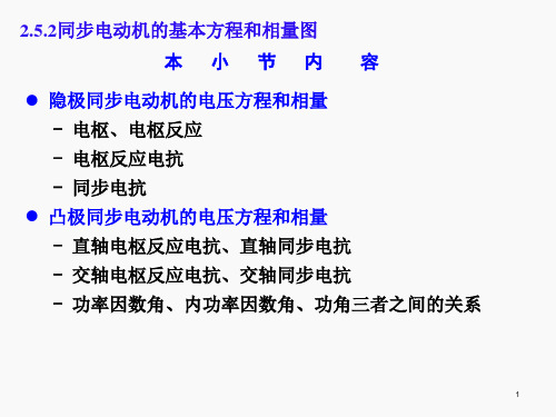
Page 15
2.5三相同步电动机
2.5.2同步电动机的基本方程和相量图 2.凸极同步电动机的电压方程和相量图
根据式(2-105)绘制相量图如图2-46a所示。
U1 E0 Ead Eaq jI1x1 E0 jId xad jIq xaq jI1x1
(2-105)
已知:
I1 Id Iq
2.5三相同步电动机 2.5.2同步电动机的基本方程和相量图 2.凸极同步电动机的电压方程和相量图
电磁关系---双方应理论
d
为了解决电枢磁动势Fa在不同位
置时遇到不同气隙,其磁阻计算困难
的问题,可将电枢磁动势分解成两个 Fa
Fad
分量:一个分量是直轴电枢磁动势, 用Fad表示,它作用在直轴方向;另一
图2-44凸极同步电动机电枢反应磁动势
Page 9
2.5三相同步电动机 2.5.2同步电动机的基本方程和相量图
x
L
N 2m
N2
A
l
d 直轴
d
N
电枢磁动势Fa
2.凸极同步电动机的电压方程和相量图 q
q 交轴q N
Sq
电磁关系---凸极机的电枢反应电抗:
S
d
d
当定子电流I1产生的电枢磁动势Fa与主磁极轴线重合,气 隙最小,磁阻最小,磁导最大,相应的电抗为最大;这时所对 应的电枢电抗称为直轴电枢反应电抗,用xad表示;
Iq I1 cos
a)根据式(2-105) b)根据式(2-107)
图2-46 凸极同步电动机相量图
Page 17
jxq I1
E0 jId xd
EQ
jId xq
jI1xq
I1
S
1三相交流电压表达式2基本空间矢量对应图
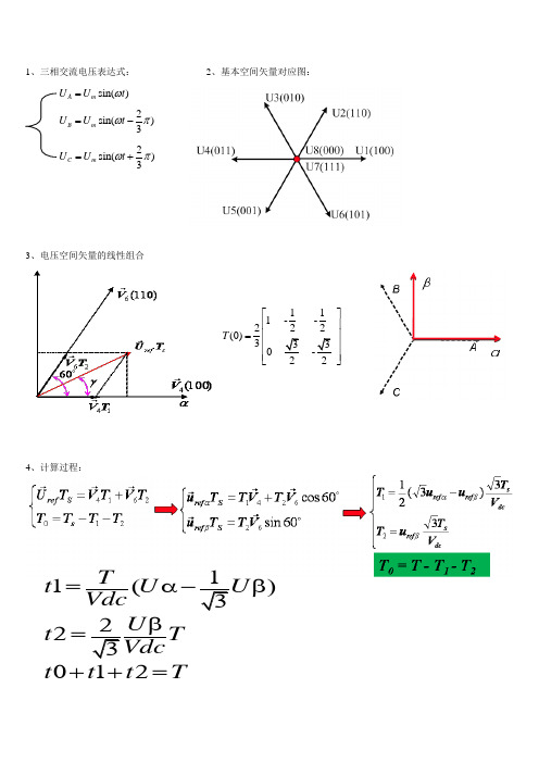
sin()A m U U t ω=2sin()3B m U U t ωπ=-2sin()3C m U U t ωπ=+1、三相交流电压表达式:2、基本空间矢量对应图:3、电压空间矢量的线性组合4、计算过程:111 - -222(0)3330 T ⎡⎤⎢⎥⎢⎥=⎢⎥⎢⎥⎣⎦1(323012T t U Vdc U t T Vdct t t T=α-β)β=++=5、各扇区的矢量作用时间:227、T1和T2赋值表:/,,X T Udc Y Udc U Z Udc U ==/2+3/2)T/=/2-3/2)βT ααα/β定义:注意:扇区号2 1 13 3 2 1 2 3 1 2 3 3322112T ta tb tAon tBon tAon tatCon tBon ta --==+=+三电平开发计算一、三电平矢量图:二、矢量模分类:1、长矢量(v13-v18),2、中矢量(v7-v12),短矢量(v1-v6),零矢量(v0):扇区号Su-Sv-Sw αβVo1 1 1 0 0 0 0 0 0 0 -1 -1 -1 0 0612,34,sin63M M Mπθππθθ⎧⎫≤⎪⎪===⎬⎪⎪⎪⎪⎩⎭二、三电平逆变器的整个矢量空间分为此个大区,每个区又分成四个小区,当Vr位于1扇区中四个小三角形中矢量作用时间计算式:001122012Vr AV T V T V T VrTsT T T Ts++=⎧⎫⎨⎬++=⎩⎭位于三角形中,三个顶点矢量作用时间式:1013172012Vr BV T V T V T VrTsT T T Ts++=⎧⎫⎨⎬++=⎩⎭位于三角形中,三个顶点矢量作用时间式:107122012Vr CV T V T V T VrTsT T T Ts++=⎧⎫⎨⎬++=⎩⎭位于三角形中,三个顶点矢量作用时间式:7021142012Vr DV T V T V T VrTsT T T Ts++=⎧⎫⎨⎬++=⎩⎭位于三角形中,三个顶点矢量作用时间式:三、当Vr位于1扇区中四个小三角形选择计算式:1、首先定义三电平逆变器电压空间矢量调制比:3223Vr VrmUdUd==其中|Vr|是旋转电压矢量Vr的模长,其旋转有角速度ω=2Πf,2Ud/3是电压矢量V12的模长。
对称负载下三相同步发电机的电压向量图翻译

文章出处: R. H. Park, Electric Machinery, John Wiley, New York,2006对称负载下三相同步发电机的电压向量图电压向量图对分析同步电机的运行状况有着非常重要的作用。
从电压向量图上,我们可以得到同步电机电压变化率,即由于负载减小电压的升高和发电机从空载到负载过程中电压的下降等。
这些问题的解决具有重要意义:(1)在最初设计时要确定在不同的运行条件下所需的励磁电流;(2)在对已造好的电机进行测试时,判定其性能是否与原技术设计书中一致。
有了电压向量图,也使我们不必实际地施加负载,就能确定电机的运行状态。
当电机的容量较大时,要实际地施加负载是特别困难的。
电压向量图可以使我们能够通过计算机得到电机的主要运行特性。
最后,用电压向量图可以确定由励磁磁场产生的电势与端电压之间的功率角θ。
θ角无论在稳态还是在瞬态情况下,在分析电机产生的转矩和功率时起着重要作用。
由励磁磁通产生的电势E0’和同步电机端电压V’之间的向量差,取决于电枢反应的影响和电枢绕组的电阻和漏感抗上的电压降。
由于电枢反应的影响与电机的类型(凸极机还是隐极机),负载的性质(感性、电阻性还是电容性)和负载的平衡度(对称的还是不对称的)有很大关系,因此在画电压向量图时,所有这些因素都必须充分考虑到。
需要牢记的是,电压向量图中所有的电势和电压向量都是基波频率,因此所有的电势和电压都必须事先进行谐波分析,然后从这些谐波中将基波分离出来。
在讨论电枢反应的那一章中,已经分析了可以获得由与电机转子同步的电枢磁场分量产生的基波电压。
当一台电机将要交付使用时,技术人员根据从空载和短路特性实验中获得的数据绘出其电压向量图。
端电压是以下各因素共同作用的结果:(a)基波磁极磁势产生磁通Ф0,进而感应基波电势E0;(b)正比于负载电流的纵轴分量I d(其相对电势E0呈纯感性)的纵轴电枢反应磁势F ad ;(c)正比于负载电流的纵轴的横轴分量I q(其相对电势E0呈纯电阻性)的横轴反应磁势F aq ;正比于负载电流的漏电势Eσa=xσa I ;(e)定子绕组的纯电阻性电压降Ir a。
- 1、下载文档前请自行甄别文档内容的完整性,平台不提供额外的编辑、内容补充、找答案等附加服务。
- 2、"仅部分预览"的文档,不可在线预览部分如存在完整性等问题,可反馈申请退款(可完整预览的文档不适用该条件!)。
- 3、如文档侵犯您的权益,请联系客服反馈,我们会尽快为您处理(人工客服工作时间:9:00-18:30)。
Voltage Diagrams of the Three-Phase SynchronousGenerator on Balanced LoadThe voltage diagram is of very great importance for analyzing working conditions in a synchronous machine. It is possible to obtain from the voltage diagram the per cent variation of the synchronous generator voltage, the voltage increase with a drop in load and drop voltage for the transition from operation on no-load to operation on-load. The solution of these problems is of great importance: (1) for initial machine design when the necessary excitation current values are to be determined under various operating conditions and (2) when testing a finished machine to decide whether the machine conforms to given technical specifications. By using a voltage diagram, it is also possible to determine the operating conditions of a machine without actually applying the load, something which becomes especially difficult when the machine is of large rating.The voltage diagrams make it possible to obtain the fundamental performance characteristics of a machine by means of calculation. Finally, the voltage diagram allows to determine the power angle θ between the e. m. f. produced by the excitation field and the voltage across the terminals. Angle θplays a very important role in the analysis of the torque and power developed by a machine both in the steady-state and transient conditions.The vector difference between the e. m. f. E0due to the excitation flux and the terminal voltage V of a synchronous machine depends on the effect of the armature reaction and on the voltage drop in the active resistance and leakage inductive reactance of the armature winding.Since armature reaction depends to a very great extent on the type of the machine ( salient-pole or non-salient-pole ) , kind of load ( inductive, active or capacitive ) and on the degree of load symmetry ( balanced or unbalanced ) , all these factors must be duly considered when plotting a voltage diagram.It is necessary to bear in mind that all the e. m. f. s and voltages that participate as components in the voltage diagram should correspond to its fundamental frequency; therefore, all the e. m. f. s and voltages must preliminarily be resolved into harmonics and from each of them the fundamental wave must be taken separately. In the chapter where the armature reaction is considered an analysis was carried out which allowed to obtain the fundamental voltage wave produced by the armature field components revolving in step with the machine rotor.When a new machine is being commissioned, a vector diagram is plotted from the test data obtained from the experimental no-load and short-circuitcharacteristics.The voltage across the terminals is the result of the action of the following factors : (a) the fundamental pole m. m. f. creating fluxФ0 which induces the fundamental e. m. f. E0; (b) the direct-axis armature reaction m. m. f.F ad proportional to the load-current component I d , reactive in respect to the e. m. f. E0 ; (c) the quadrature-axis armature reaction m. m. f. F aq proportional to the current I q component , active in respect to the e. m. f. ; (d) the leakage e. m. f. Eσa=xσa I , proportional to the load current I ; (e) the active voltage drop in stator winding Ir a . Since when I=I n the voltage drop Ir a is less than 1% of the rated voltage, in most cases it may be neglected.The diagram may be constructed by two different methods. In the first method of construction of the vector diagram it is assumed that each m. m. f. exists separately and produces its own magnetic flux, the latter creating its own e. m. f. Thus, four separate fluxes and, accordingly, four e. m. f. s created by them appear in the machine, viz: (a) the excitation fluxФ0’and the fundamental e. m. f. E0’; (b) the flux and the e. m. f. of the direct-axis armature-reactionФad’and E ad’; (c) the flux and e. m. f. of the quadrature-axis armature-reactionФaq’ and E aq’; and (d) the fluxФσa’ and the e. m. f. Eσa’ of armature-winding leakage. If we also take into account the active voltage drop, which, when taken with opposite sign, may be considered as an e. m. f. E r’=-Ir a’, the vector sum of the e. m. f. s. listed above gives as a result the magnitude and phase of the terminal voltage vector V’.Since the vector summation of fluxes and the corresponding e. m. f. s. induced by them by the superposition method is legitimate only when the reluctances are constant in all sections of the magnetic circuit of the machine, this method is directly applicable to the unsaturated magnetic circuit of a synchronous machine. When using this method for machines with a saturated circuit, it is necessary to take into account the actual reluctances of the parts of the magnetic circuit at the given operating conditions and assume that the reluctances are constant so far as the given operating conditions are concerned. The results obtained will be correct, nevertheless it is difficult to determine the real magnetic conditions of the machine.Since by this method a vector summation of synchronous machine e. m. f. s is carried out, the voltage vector diagram obtained in this case may be called the e. m. f. diagram.From the theoretical point of view, this diagram is of very great methodological importance, since it allows to assess with the necessary completeness, the entire combination of factors determining, in the end, the voltage across the synchronous generator terminals, notwithstanding the fact that, for purposes of calculation and test, the diagram is somewhatcomplicated. Therefore, for a series of practical purposes the e. m. f. diagram is given a number of modifications to bring it into a more simple and convenient form.The method that is of greatest interest is the Blondel two-reaction theory, according to which all fluxes due to the load current I, including leakage flux Фσa‘, are resolved along the direct and quadrature-axes. In connection with this, we introduce the concept of synchronous machine direct and quadrature-axes reactances x d and x q, and their components, which represent some of the fundamental parameters of a synchronous machine and serve for assessment of its performance characteristics.By the second method we may determine first the resultant m. m. f. of the generator, obtained as the result of interaction of the excitation m. m. f. with a armature-reaction m. m. f. , and, having found from it the resultant flux in the air gapФδ,then determine the e. m. f. Eδactually induced in the machine. By subtracting vectorially from e. m. f. Eδ’ the inductive voltage drop in the leakage reactance j Ixσa’and the active voltage drop Ir a’, we may find the resultant voltage across the generator terminals.The diagram of m. m. f. s and e. m. f. s obtained in this case is called the Potier regulation, or e. m. f. diagram.For balanced load conditions, assuming that the parameters of all phases are equal, we may restrict the construction to a diagram for one phase only.It should be noted that the vector diagrams constructed for a synchronous generator operating as a generator may be readily extended to its operation as a synchronous motor and a synchronous condenser.The most simple voltage diagram is obtained for balanced load of a synchronous non-salient-pole generator with an unsaturated magnetic system. We shall therefore begin the discussion with the latter generator.Let us construct the e. m. f. diagram of a synchronous non-salient-pole generator first for the case of inductive load, when 0<φ<90o. Align the vector of the generator voltage across the generator terminals with the positive direction of the ordinate axis and draw the current vector I’ lagging behind the voltage vector V’ by an angle φ. Then draw the vector of the e. m. f. E0’ produced by the magnetic excitation fluxФ0’, as leading the current vector I’ by an angle φ. According to the general rule, fluxФ0’ leads the e. m. f. vector E0’ by 90o.The fundamental wave of the armature-reaction m. m. f. F a’of a synchronous generator rotates in step with its rotor. In a non-salient-pole type machine the difference between permeances along the direct axis andquadrature axes mat be neglected, and if may be assumed that m. m. f. F a’creates only a sine wave of reaction fluxФa’. This flux coincides in phase with the current I’ and induces in the stator winding an e. m. f. F a’lagging in phase behind I’by 90o.If x a is the inductive reactance of armature reaction for a non-salient-pole machine, then E a’=-j I’x a.By vector addition of the flux vectorsФ0’ and Фa’ and, respectively, the e. m.f. vectors E0’ and E a’ we obtain : (1) the vector of the resultant flux Фδ’ which actually exists in the generator air gap and determines the saturation of its magnetic circuit, and (2) the vector of the resultant e. m. f. Eδ’ in the stator winding, proportional to flux Фδ’ and lagging behind it by 90o.Existing together with the armature-reaction flux is a stator winding leakage flux Фδa’ , the vector of which, like that of flux Фa’, coincides in phase with current I’and creates in the stator winding a leakage of fundamental frequency Eσa’ =-j I’xσa lagging in phase behind current by 90o. Here xσa is the leakage reactance of the stator winding. Besides, it is necessary to take into account the e. m. f. E r’ =-I’r a which is opposite in phase to current I’; here r a is the active resistance of the stator winding.By vector addition of the e. m. f. vectors E0’ , E a’ , Eσa’ and E r’ , or, what is the same, the e. m. f. s E a’,Eσa’ and E r’ , we obtain the vector V’ of the voltage across the generator terminals. The angle φ by which current I’lags behind voltage V’is determined by the parameters of the external power circuit to which the generator is connected and feeds into. The vector V c’of the line voltage is in opposition to generator voltage vector V’.When constructing the vector diagrams of a synchronous machine, it is not e. m. f. s E a’,Eσa’ and E r’ that are represented, but their inverse values, which are the reactive and active voltage drops in the given sections of the circuit, i. e.-E a’=j I’x a, - Eσa’= j I’xσa, -E r’=I’r aIn this case the voltage diagram gives, obviously, the resolution of the e. m.f. E0’ due to the excitation flux into components representing the voltage drops j I’x a, j I’xσa and j I’r a and the generator terminal voltage V’. On the other hand, the voltage diagram show not the fluxesФ0’,Фa’ and Фδ’, but the m. m. f. s F0’, F a’and Fδ’ which produce them ; this makes it legitimate to call it the e. m. m. f. diagram.The voltage drop vectors j I’x a and j I’xσa may be substituted for by a common voltage drop vectorj I’x a + j I’xσa = j I’x swhere the reactancex s = x a+ xσais termed the synchronous reactance of the salient-pole machine.It is interesting to represent the relative arrangement in space of the main parts of machine , the stator and the rotor ,and the windings on them , together with the m. m. f. s they create . Angle φ indicates the space displacement of the conductors carrying maximum current I relatives to the conductors which have maximum e. m. f. E0and are opposite the pole axis .By this same angle φcurrent I’ lags behind e. m. f. E0’ in time phase . If we add the m. m. f. vector F a’to the excitation winding m. m. f. vector F0’ , we shall obtain the resultant m. m.f. vector Fδ’ which lags in space from F0’ by the same angleθ’ ,by which the e. m.f. Fδ’ lags behind e. m. f. E0’ in time phase .。