常用时序分析SDC 命令参考
sdc语法

sdc语法Sdc语法是一种常用于硬件定义的语言,可以帮助工程师更清晰地描述电路结构和性能特征。
下面,我们来探讨一下Sdc语法的相关内容。
一、Sdc语法的基本概念与使用1. 高层次约束和低层次约束高层次约束是指设计时对电路主要功能和时序性能的描述。
低层次约束则是对电路细节,如电平转换延迟等的描述。
在Sdc语法中,通常先定义高层次约束,再定义低层次约束。
2. 时钟时钟信号在电路中起到重要的作用。
在Sdc语法中,我们会使用时钟周期(clock period)来描述时钟信号的周期性。
时钟约束有两种方式:带时钟约束(with clock)和不带时钟约束(without clock)。
3. 延迟延迟(delay)是描述电路中信号传递时间的一个重要参数。
在Sdc语法中,我们会使用时钟偏移(clock offset)和延迟值(delay value)来描述信号的传输时间。
4. 结构描述在Sdc语法中,我们可以使用实体声明(entity declaration)来描述电路的结构。
实体声明主要包括输入(input)、输出(output)和内部节点(internal node)等基本元素。
5. 路径约束路径约束是用来描述信号在电路中的传输路径的。
包括顺序路径(sequential path)和组合路径(combinational path)两种。
在Sdc语法中,我们会使用时钟偏移、时钟周期、延迟等参数来描述信号传输路径的约束条件。
二、Sdc语法的应用场景1. 时序优化在设计电路时,我们通常需要对电路的时序进行优化。
在Sdc语法中,我们可以通过定义时序约束来完成对时序的优化。
2. 针对时序问题的调试在电路设计过程中,时序问题是十分普遍的。
在Sdc语法中,我们可以通过设置时钟偏移、延迟等参数来定位和解决时序问题。
3. 电路仿真在电路仿真中,我们可以使用Sdc语法来定义仿真测试和分析环节。
通过定义时序约束,我们可以对电路的性能和行为进行详细的分析和测试。
静态时序分析基础及应用1(下)
前言在制程进入深次微米世代之后,晶片(IC)设计的高复杂度及系统单晶片(SOC)设计方式兴起。
此一趋势使得如何确保IC品质成為今日所有设计从业人员不得不面临之重大课题。
静态时序分析(Static Timing Analysis简称STA)经由完整的分析方式判断IC是否能够在使用者指定的时序下正常工作,对确保IC品质之课题,提供一个不错的解决方案。
在「静态时序分析(Static Timing Analysis)基础及应用(上)」一文中笔者以简单叙述及图例说明的方式,对STA的基础概念做了详尽的说明。
接下来,就让我们藉由实际设计范例来瞭解STA在设计流程的应用。
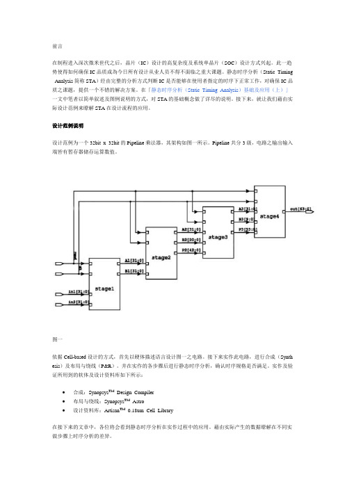
设计范例说明设计范例为一个32bit x 32bit的Pipeline乘法器,其架构如图一所示。
Pipeline共分3级,电路之输出输入端皆有暂存器储存运算数值。
图一依据Cell-based设计的方式,首先以硬体描述语言设计图一之电路。
接下来实作此电路,进行合成(Synth esis)及布局与绕线(P&R)。
并在实作的各步骤后进行静态时序分析,确认时序规格是否满足。
实作及验证所用到的软体及设计资料库如下所示:∙合成:Synopsys TM Design Compiler∙布局与绕线:Synopsys TM Astro∙设计资料库:Artisan TM0.18um Cell Library在接下来的文章中,各位将会看到静态时序分析在实作过程中的应用。
藉由实际产生的数据瞭解在不同实做步骤上时序分析的差异。
时序限制(Timing Constraint)要作静态时序分析,首先要有时序限制。
此设计范例的时序限制如下所述。
(→后為设定时序限制之SD C指令)1 时脉规格(Clock Specification)1.1 週期:6ns →create_clock -name "MY_CLOCK" -period 6 -waveform {0 3} [get_ports {clk}]1.2 Source Latency:1ns →set_clock_latency -source 1 [get_clocks {MY_CLOCK}]1.3 Network Latency:1ns →set_clock_latency 1 [get_clocks {MY_CLOCK}]1.4 Skew:0.5ns →set_clock_uncertainty 0.5 [get_clocks {MY_CLOCK}]2 周边状况(Boundary Condition)2.1 输入延迟(Input Delay):1.2ns →set allin_except_CLK [remove_from_collection [all_inputs] [get_po rts clk] ]set_input_delay $I_DELAY -clock MY_CLOCK $allin_except_CLK2.2 输出延迟(Output Delay):1.2ns →set_output_delay $O_DELAY -clock MY_CLOCK [all_outputs]2.3 输出负载(Output Loading):0.5pF →set_load $O_LOAD 0.5 [all_outputs]3 时序例外(Timing Exception):无合成软体之时序报告当Synopsys Design Compiler将电路合成完毕后,执行下面指令可以產生时序报告:report_timing -path full -delay max -max_paths 10 -input_pins \-nets -transition_time -capacitance > timing_syn.txt时序报告会储存在timing_syn.txt此档案中。
SDC 时序约束(1) - create_clock
SDC 时序约束(1) - create_clock在写 .sdc 约束文件时,要做的第一件事情就是使用 create_clock 对进入 FPGA 的时钟进行约束。
其语法格式如下:create_clock [-add] [-name <clock_name>] -period <value> [-waveform <edge_list>] <targets>参数解释:-name 表示生成的时钟名称-period 表示时钟周期,单位为 ns-waveform 可以详细描述时钟占空比及其上下移位置<targets>端口列表-add 用于为一个端口添加多个时钟约束例子:create_clock -period 10 -name clk_100 [get_ports clk]生成了一个周期为 10ns 占空比为 50% 的时钟,其名字为 clk_100,其端口名为 clkcreate_clock -period 10 -waveform {8 12} -name clk [get_ports clk]生成一个周期为 10ns 上升沿 8ns,下降沿 2ns 的时钟create_clock -period 10 -name clk_100 [get_ports clk]create_clock -perioid 6.6 -name clk_150 -add [get_ports clk]在 clk 一个端口上生成两个时钟,其周期分别为 10ns 和 6.6ns 。
如果一个系统中同一个端口在不同时刻会有多种时钟输入,可以使用 -add 参数。
否则,如果不添加 -add 参数,后面定义的时钟无效。
注1:在 Tcl 语法中 [] 表示命令替换,因此 [get_ports fpga_clk] 将执行一个命令找到设计中与 fpga_clk 名字相符的端口。
时序分析sdc文档
Using the Synopsys® Design Constraints Format Application NoteVersion 1.9, December 2010Copyright Notice and Proprietary InformationCopyright © 2010 Synopsys, Inc. All rights reserved. This software and documentation contain confidential and proprietary information that is the property of Synopsys, Inc. The software and documentation are furnished under a license agreement and may be used or copied only in accordance with the terms of the license agreement. No part of the software and documentation may be reproduced, transmitted, or translated, in any form or by any means, electronic, mechanical, manual, optical, or otherwise, without prior written permission of Synopsys, Inc., or as expressly provided by the license agreement.Right to Copy DocumentationThe license agreement with Synopsys permits licensee to make copies of the documentation for its internal use only. Each copy shall include all copyrights, trademarks, service marks, and proprietary rights notices, if any. Licensee must assign sequential numbers to all copies. These copies shall contain the following legend on the cover page:“This document is duplicated with the permission of Synopsys, Inc., for the exclusive use of __________________________________________ and its employees. This is copy number __________.”Destination Control StatementAll technical data contained in this publication is subject to the export control laws of the United States of America. Disclosure to nationals of other countries contrary to United States law is prohibited. It is the reader’s responsibility to determine the applicable regulations and to comply with them.DisclaimerSYNOPSYS, INC., AND ITS LICENSORS MAKE NO WARRANTY OF ANY KIND, EXPRESS OR IMPLIED, WITH REGARD TO THIS MA TERIAL, INCLUDING, BUT NOT LIMITED TO, THE IMPLIED WARRANTIES OF MERCHANTABILITY AND FITNESS FOR A P ARTICULAR PURPOSE.Registered Trademarks (®)Synopsys, AEON, AMPS, Astro, Behavior Extracting Synthesis Technology, Cadabra, CA TS, Certify, CHIPit, CODE V , CoMET , Confirma, Design Compiler, DesignWare, EMBED-IT!, Formality, Galaxy Custom Designer, Global Synthesis, HAPS, HapsT rak, HDL Analyst, HSIM, HSPICE, Identify, Leda, LightT ools, MAST , METeor, ModelTools, NanoSim, NOVeA, OpenVera, ORA, PathMill, Physical Compiler, PrimeTime, SCOPE, Simply Better Results, SiVL, SNUG, SolvNet, Sonic Focus, ST AR Memory System, Syndicated, Synplicity, Synplify, Synplify Pro, Synthesis Constraints Optimization Environment, T etraMAX, the Synplicity logo, UMRBus, VCS, Vera, and YIELDirector are registered trademarks of Synopsys, Inc.Trademarks (™)AFGen, Apollo, ARC, ASAP , Astro-Rail, Astro-Xtalk, Aurora, AvanWaves, BEST, Columbia, Columbia-CE, Cosmos, CosmosLE, CosmosScope, CRITIC, CustomExplorer, CustomSim, DC Expert, DC Professional, DC Ultra, Design Analyzer, Design Vision, DesignerHDL, DesignPower, DFTMAX, Direct Silicon Access, Discovery, Eclypse, Encore, EPIC, Galaxy, HANEX, HDL Compiler, Hercules, Hierarchical Optimization Technology, High-performance ASIC Prototyping System, HSIM plus , i-Virtual Stepper, IICE, in-Sync, iN-Tandem, Intelli, Jupiter, Jupiter-DP , JupiterXT, JupiterXT -ASIC, Liberty, Libra-Passport, Library Compiler, Macro-PLUS, Magellan, Mars, Mars-Rail, Mars-Xtalk, Milkyway, ModelSource, Module Compiler, MultiPoint, ORAengineering, Physical Analyst, Planet, Planet-PL, Polaris, Power Compiler, Raphael, RippledMixer, Saturn, Scirocco, Scirocco-i, SiWare, Star-RCXT, Star-SimXT, StarRC, System Compiler, System Designer, T aurus, T otalRecall, TSUPREM-4, VCSi, VHDL Compiler, VMC, and Worksheet Buffer are trademarks of Synopsys, Inc.Service Marks (SM )MAP-in, SVP Café, and T AP-in are service marks of Synopsys, Inc.SystemC is a trademark of the Open SystemC Initiative and is used under license.ARM and AMBA are registered trademarks of ARM Limited.Saber is a registered trademark of SabreMark Limited Partnership and is used under license.All other product or company names may be trademarks of their respective owners.ContentsWhat’s New in This Release. . . . . . . . . . . . . . . . . . . . . . . . . . . . . . . . . . . . . . . . . . . viAbout This Application Note. . . . . . . . . . . . . . . . . . . . . . . . . . . . . . . . . . . . . . . . . . . viiCustomer Support. . . . . . . . . . . . . . . . . . . . . . . . . . . . . . . . . . . . . . . . . . . . . . . . . . . x ing the Synopsys Design Constraints FormatAbout the SDC Format. . . . . . . . . . . . . . . . . . . . . . . . . . . . . . . . . . . . . . . . . . . . . . . 1-3 Specifying the SDC Version. . . . . . . . . . . . . . . . . . . . . . . . . . . . . . . . . . . . . . . . 1-3 Specifying the Units. . . . . . . . . . . . . . . . . . . . . . . . . . . . . . . . . . . . . . . . . . . . . . 1-4 Specifying the Design Constraints. . . . . . . . . . . . . . . . . . . . . . . . . . . . . . . . . . . 1-4 Specifying Design Objects . . . . . . . . . . . . . . . . . . . . . . . . . . . . . . . . . . . . . 1-6 Using Comments. . . . . . . . . . . . . . . . . . . . . . . . . . . . . . . . . . . . . . . . . . . . . . . . 1-8Generating SDC Files. . . . . . . . . . . . . . . . . . . . . . . . . . . . . . . . . . . . . . . . . . . . . . . . 1-9 Generating SDC Files From a Synopsys Tool. . . . . . . . . . . . . . . . . . . . . . . . . . 1-9 About the Generated SDC File. . . . . . . . . . . . . . . . . . . . . . . . . . . . . . . . . . 1-10 Using Synopsys Tools to Validate SDC Files. . . . . . . . . . . . . . . . . . . . . . . . . . . 1-12Reading SDC Files Into a Synopsys Tool. . . . . . . . . . . . . . . . . . . . . . . . . . . . . . . . . 1-13 Determining the SDC Version . . . . . . . . . . . . . . . . . . . . . . . . . . . . . . . . . . . . . . 1-13 Determining the Hierarchy Separator Character . . . . . . . . . . . . . . . . . . . . . . . . 1-13Managing Large SDC Files. . . . . . . . . . . . . . . . . . . . . . . . . . . . . . . . . . . . . . . . . . . . 1-14 Appendix A.SDC SyntaxUsing the Synopsys Design Constraints Format Application Note 1.9 Using the Synopsys Design Constraints Format Application Note Version 1.9PrefaceThis preface includes the following sections:•What’s New in This Release•About This Application Note•Customer SupportUsing the Synopsys Design Constraints Format Application Note 1.9 Using the Synopsys Design Constraints Format Application Note Version 1.9What’s New in This ReleaseThis section describes the enhancements included in Synopsys Design Constraints (SDC) version 1.9.EnhancementsSDC version 1.9 includes the following enhancements:•Support for the -comment option for certain SDC commands. This option enables you to include a user-specific comment. The comment string associated with the specificcommnad is written out when you use the write_sdc or write_script command. Y ou receive a message if a comment is too long or the overall allocated storage is reached.The following SDC commands support the -comment option:•create_clock•create_generated_clock•group_path•set_clock_group•set_false_path•set_max_delay•set_min_delay•set_multicycle_pathThe following example shows how you would use the -comment option:create_clock -period 10 [get_ports CLK] -comment “for block1.rev0 in Test Mode”Using the Synopsys Design Constraints Format Application Note Version 1.9Known Limitations and Resolved STARsInformation about known problems and limitations, as well as about resolved Synopsys Technical Action Requests (ST ARs), is available in the product release notes in SolvNet.To see the product release notes,1.Go to the Download Center on SolvNet located at the following address:https:///DownloadCenterIf prompted, enter your user name and password. If you do not have a Synopsys username and password, follow the instructions to register with SolvNet.2.Select the product, and then select a release in the list that appears.About This Application NoteThis application note describes the methodology and commands used to transfer constraint information between Synopsys tools and third-party tools using version 1.9 of the SDC format.SDC version 1.9 is introduced in the E-2010.12 releases of PrimeTime, Design Compiler, and IC Compiler. It is the recommended SDC version to use with version E-2010.12 and later of these tools.AudienceThis application note is for engineers who use the SDC format to transfer constraintinformation between Design Compiler, IC Compiler, or PrimeTime and third-party tools.Using the Synopsys Design Constraints Format Application Note 1.9 Using the Synopsys Design Constraints Format Application Note Version 1.9Related PublicationsFor additional information about SDC, see the documentation on SolvNet at the following address:https:///DocsOnWebY ou might also want to see the documentation for the following related Synopsys products:•Design Compiler•IC Compiler•PrimeTimeUsing the Synopsys Design Constraints Format Application Note Version 1.9ConventionsThe following conventions are used in Synopsys documentation.Convention DescriptionCourier Indicates syntax, such as write_file.Courier italic Indicates a user-defined value in syntax, such aswrite_file design_list.Courier bold Indicates user input—text you type verbatim—inexamples, such asprompt> write_file top[ ]Denotes optional arguments in syntax, such aswrite_file [-format fmt]...Indicates that arguments can be repeated as manytimes as needed, such aspin1 pin2 ... pinN|Indicates a choice among alternatives, such aslow | medium | highControl-c Indicates a keyboard combination, such as holdingdown the Control key and pressing c.\Indicates a continuation of a command line./Indicates levels of directory structure.Edit > Copy Indicates a path to a menu command, such asopening the Edit menu and choosing Copy.Using the Synopsys Design Constraints Format Application Note 1.9 Using the Synopsys Design Constraints Format Application Note Version 1.9Customer SupportCustomer support is available through SolvNet online customer support and throughcontacting the Synopsys Technical Support Center.Accessing SolvNetSolvNet includes a knowledge base of technical articles and answers to frequently asked questions about Synopsys tools. SolvNet also gives you access to a wide range of Synopsys online services including software downloads, documentation, and technical support.To access SolvNet, go to the following address:https://If prompted, enter your user name and password. If you do not have a Synopsys user name and password, follow the instructions to register with SolvNet.If you need help using SolvNet, click HELP in the top-right menu bar.Contacting the Synopsys Technical Support CenterIf you have problems, questions, or suggestions, you can contact the Synopsys T echnical Support Center in the following ways:•Open a support case to your local support center online by signing in to SolvNet at https://, clicking Support, and then clicking “Open A Support Case.”•Send an e-mail message to your local support center.•E-mail support_center@ from within North America.•Find other local support center e-mail addresses at/Support/GlobalSupportCenters/Pages•Telephone your local support center.•Call (800) 245-8005 from within North America.•Find other local support center telephone numbers at/Support/GlobalSupportCenters/Pages1Using the Synopsys Design Constraints FormatSynopsys Design Constraints (SDC) is a format used to specify the design intent, including the timing, power, and area constraints for a design. SDC is based on the tool command language (Tcl). The Synopsys Design Compiler, IC Compiler, and PrimeTime tools use the SDC description to synthesize and analyze a design. In addition, these tools can generate SDC descriptions for and read SDC descriptions from third-party tools. This application note describes how to share constraint information between third-party EDA tools and these Synopsys tools using SDC files. Figure 1-1 shows this SDC-based interface.Use the SDC-based flow described in this document to share constraint informationbetween Synopsys and third-party EDA tools.Using the Synopsys Design Constraints Format Application Note 1.9Using the Synopsys Design Constraints Format Application Note Version 1.9Figure 1-1 SDC-Based Constraint InterfaceNote:There are slight differences between the SDC files generated by the Synopsys tools. For more information, see “About the Generated SDC File” on page 1-10.This application note describes the SDC-based interface in the following sections:•About the SDC Format•Generating SDC Files•Reading SDC Files Into a Synopsys Tool•Managing Large SDC Files SDC fileThird-party write_sdcread_sdcSDC fileEDA toolSynopsys toolSynopsystoolUsing the Synopsys Design Constraints Format Application Note Version 1.9About the SDC FormatSDC is a Tcl-based format. All commands in an SDC file conform to the Tcl syntax rules.Y ou use an SDC file to communicate the design intent, including timing and arearequirements between EDA tools. An SDC file contains the following information:•The SDC version (optional)•The SDC units (optional)•The design constraints•Comments (optional)Note:An SDC file does not contain commands to load or link the design. Y ou must performthese tasks before reading an SDC file.Specifying the SDC VersionThe sdc_version variable specifies the SDC version for the file. To specify the SDC version, set this variable in the first command in the SDC file:set sdc_version valueIf the SDC file does not specify a version, Design Compiler, IC Compiler, and PrimeTime assume that the file uses SDC version 1.9 syntax. The SDC syntax is specified in Appendix A, “SDC Syntax.”If the SDC file does not specify a version, the assumed version depends on the tool reading the file. Set this variable in your SDC file to ensure compatability.SDC version 1.9 is introduced in the E-2010.12 release of PrimeTime, Design Compiler, and IC Compiler. It is the recommended SDC version to use with version E-2010.12 and later of these tools.If the third-party EDA tool you are using supports an earlier version of the SDC format, set this variable to ensure compatibility with the Synopsys tools.Using the Synopsys Design Constraints Format Application Note 1.9 Using the Synopsys Design Constraints Format Application Note Version 1.9Specifying the UnitsThe set_units command specifies the units used in the SDC file. Y ou can specify the units for capacitance, resistance, time, voltage, current, and power.The syntax of the set_units command isset_units -capacitance cap_unit -resistance res_unit-time time_unit -voltage voltage_unit-current current_unit -power power_unitSpecifying the Design ConstraintsY ou specify design constraints using Synopsys constraint commands. Y ou can break up a long command line into multiple lines by using the backslash character (\) to indicatecommand continuation. The SDC format consists of the Synopsys constraint commands listed in Table 1-1.Note:The SDC format supports a subset of the command arguments, as compared to thearguments supported by the individual tools. For a listing of the supported arguments,see Appendix A, “SDC Syntax.” For information about individual tool support, seeSolvNet article 015193. For information about validating your SDC file, see “UsingSynopsys Tools to Validate SDC Files” on page 1-12.Table 1-1 SDC CommandsType of information CommandsOperating conditions set_operating_conditionsWire load models set_wire_load_min_block_sizeset_wire_load_modeset_wire_load_modelset_wire_load_selection_groupSystem interface set_driveset_driving_cellset_fanout_loadset_input_transitionset_loadset_port_fanout_numberUsing the Synopsys Design Constraints Format Application Note Version 1.9Table 1-1 SDC Commands (Continued)Type of information CommandsDesign rule constraints set_max_capacitanceset_max_fanoutset_max_transitionset_min_capacitanceTiming constraints create_clockcreate_generated_clockgroup_pathset_clock_gating_checkset_clock_groupsset_clock_latencyset_clock_senseset_clock_transitionset_clock_uncertaintyset_data_checkset_disable_timingset_ideal_latencyset_ideal_networkset_ideal_transitionset_input_delayset_max_time_borrowset_output_delayset_propagated_clockset_resistanceset_timing_derateTiming exceptions set_false_pathset_max_delayset_min_delayset_multicycle_pathArea constraints set_max_areaUsing the Synopsys Design Constraints Format Application Note 1.9Using the Synopsys Design Constraints Format Application Note Version 1.9Specifying Design ObjectsMost of the constraint commands require a design object as a command argument. SDC supports both implicit and explicit object specification.If you specify a simple name for an object, the Synopsys tools determine the object type by searching for the object using a prioritized object list. The priority order varies by command and is documented in each command’s man page. This is called implicit object specification.To avoid ambiguity, explicitly specify the object type by using a nested object accesscommand. For example, if you have a cell in the current instance named U1, the implicit specification is U1, while the explicit specification is [get_cells U1].Table 1-2 shows the design objects supported by the SDC format and the accesscommands used for explicit object specification.Note:The SDC format supports a subset of the access command syntax, as compared to the syntax supported by the individual tools. For a listing of the supported syntax, seeAppendix A, “SDC Syntax.” For information about individual tool support, see SolvNetarticle 015193.Multivoltage and poweroptimization constraints create_voltage_areaset_level_shifter_strategyset_level_shifter_thresholdset_max_dynamic_powerset_max_leakage_powerLogic assignments set_case_analysisset_logic_dcset_logic_oneset_logic_zeroTable 1-1 SDC Commands (Continued)Type of informationCommandsUsing the Synopsys Design Constraints Format Application Note Version 1.9Specifying Multiple ObjectsBoth the constraint commands and the object access commands follow the Tcl syntax rules. Use a Tcl list or wildcard characters to specify multiple objects. SDC supports the following wildcard characters:Note:In SDC version 1.5 and later, if you do not specify an object argument for an objectaccess command, SDC interprets the command as if you specified the * wildcardcharacter.Table 1-2 SDC Design Objects Design objectAccess command Description design current_design A container for cells.A block.clock 1get_clocksall_clocksA clock in a design.All clocks in a design.port get_portsall_inputsall_outputs An entry point to or exit point from a design.All entry points to a design.All exit points from a design.cell get_cells An instance of a design or library cell.pin get_pins An instance of a design port or library cell pin.net get_nets A connection between cell pins and design ports.library get_libs A container for library cells.lib_cell get_lib_cells A primitive logic element.lib_pin get_lib_pins An entry point to or exit point from a lib_cell.registerall_registers A sequential logic cell.1.The clock design object includes both standard clocks and generated clocks.Matches exactly one character.*Matches zero or more characters.Using the Synopsys Design Constraints Format Application Note 1.9 Using the Synopsys Design Constraints Format Application Note Version 1.9Specifying Hierarchical ObjectsThe reference point for all object specifications is the current instance. By default, thetop-level design is the current instance. Y ou can change the current instance by using the current_instance command.Design Compiler and IC Compiler always use a slash (/) as the hierarchy separator.PrimeTime supports a user-defined hierarchy separator (as specified by thehierarchy_separator variable), with a slash (/) being the default value.In some cases, the character used to indicate hierarchy levels (the hierarchy separator character) is also used within design object names. This can lead to an ambiguous hierarchy definition within the SDC file.Note:The hierarchy definition is never ambiguous within the Synopsys tool, because thesearch engines within these tools can correctly decode the object names.The SDC format supports the following characters as hierarchy separator characters: slash (/), at sign (@), caret (^), pound sign (#), period (.), and vertical bar (|), with the slash (/) being the default.To create an unambiguous hierarchy definition, the SDC file uses another character as the hierarchy separator character whenever a design uses a slash (/) within object names.Within the SDC file, a nondefault hierarchy separator character is specified either globally, using the set_hierarchy_separator statement, or locally, by using the -hsc option on the object access commands.Specifying BusesSpecify buses using the Verilog-style naming convention name[index] and enclose the name in curly braces. For example,create_clock -period 10 [get_clocks {CLK[0]}]Using CommentsY ou can add comments to an SDC file either as complete lines or as fragments after acommand.To identify a line as a comment, start the line with a pound sign (#).# This is an SDC comment line.To add a comment after a command, end the command using a semicolon, then precede the comment with a pound sign (#).create_clock -period 10 [get_ports CLK]; # comment fragmentUsing the Synopsys Design Constraints Format Application Note Version 1.9Generating SDC FilesY ou can generate an SDC file in the following ways:•Using the Synopsys Design Compiler, IC Compiler, or PrimeTime tools•Using a third-party EDA tool that supports the SDC format•Writing the file manuallyThe SDC files generated by Synopsys tools always meet the SDC format requirements. If you generate an SDC file using a third-party tool or by writing the file manually, you should validate the file syntax. For information about validating the file syntax, see “Using Synopsys Tools to Validate SDC Files” on page 1-12.Generating SDC Files From a Synopsys ToolTo generate an SDC file from Design Compiler, IC Compiler, or PrimeTime, use thewrite_sdc command.write_sdc file_nameThe write_sdc command writes the constraints for the current design and its hierarchy to the specified file. By default, the write_sdc command generates the file with the latest syntax. To generate the file with an earlier SDC version, use the -version option when you invoke the write_sdc command.When you generate an SDC file using syntax version 1.9, the write_sdc command writes the design units, as specified in the main library file, to the SDC file.The constraints can either be set from a script file or derived through characterization or budgeting. The order of commands in the SDC file does not indicate constraint precedence.The write_sdc command writes the design constraints to the SDC file in expanded format.This means that the generated SDC files contain a command for each constraint attribute that exists on each design object. Each design object is represented by its full hierarchical name and is selected by using the appropriate object access function (see Table 1-2 on page 1-7 for a listing of object access functions). Each command line contains all command options; those that are not specified on the design are assigned default values. For details about the expanded format, see “About the Generated SDC File” on page 1-10.Buses that have constraints set on them get expanded when you run the write_sdccommand. For example, if you use the set_input_delay command on a bus, then run the write_sdc command, Design Compiler, IC Compiler, and PrimeTime expand the bus name to all bits of the bus.Using the Synopsys Design Constraints Format Application Note 1.9 Using the Synopsys Design Constraints Format Application Note Version 1.9Because the constraints are written in expanded format, the size of the SDC file increases proportionately with the number of constraints. In particular, the use of timing exceptions increases the size of the generated SDC file. See “Managing Large SDC Files” onpage 1-14 for tips on how to use these large files.Note:The commands generated by the write_sdc command might differ between Synopsys tools. However, the generated commands meet the SDC requirements and capture the same intent.About the Generated SDC FileAlthough the SDC file generated by the write_sdc command captures the same intent as the constraints you specified, the format of the constraints will not be identical to the input format you used. In addition, there are slight differences between the SDC file generated by the different Synopsys tools.For example, assume you enter the following constraint:create_clock -period 100 clkThe SDC file generated by Design Compiler represents this constraint ascreate_clock -period 100 -waveform {0 50} [get_ports {clk}]The SDC file generated by PrimeTime represents this constraint ascreate_clock -name clk -period 100.000000 \-waveform { 0.000000 50.000000 } [get_ports {clk}]The SDC file generated by the write_sdc command might differ from the input constraints in the following ways:•Specification of design objects•Explicit specificationThe SDC file specifies all design objects using object access commands (seeTable 1-2 on page 1-7 for the listing of object access commands for each designobject). Because the argument to the object access commands is a Tcl list, the SDCfile expresses the design objects as a Tcl list (either as a list of strings within curlybraces ({}) or by using the Tcl list command).For example, if you specified clock CLK using the following command,create_clock -period 10 CLKthe corresponding SDC command is (the added text is shown in bold):create_clock -period 10 [get_clocks {CLK}]Using the Synopsys Design Constraints Format Application Note Version 1.9•Direct specificationDirect specification of a design object uses the object name as the argument to theobject access command. Y ou can indirectly specify design objects through use of the-of_objects option of an object access command. The SDC file specifies all objectsdirectly.For example, if you specified port IN1 using the following command,set_input_delay 5 -clock [get_clocks CLK] \[get_ports -of_objects [get_nets n_in1]]the corresponding SDC command is (changed text is shown in bold):set_input_delay 5 -clock [get_clocks {CLK}] \[get_ports {IN1}]•Wildcard expansionThe generated SDC file does not include wildcard characters. In some cases, the SDCfile includes a separate command for each design object represented by a wildcardspecification. In other cases, the SDC file includes a single command with a list ofdesign objects as its argument.For example, if you specified ports IN1, IN2, and IN3 using the following command,set_input_delay 5 -clock [get_clocks CLK] \[get_ports IN*]the corresponding SDC commands are (changed text is shown in bold):set_input_delay 5 -clock [get_clocks {CLK}] \[get_ports {IN1}]set_input_delay 5 -clock [get_clocks {CLK}] \[get_ports {IN2}]set_input_delay 5 -clock [get_clocks {CLK}] \[get_ports {IN3}]If you specified ports IN1, IN2, and IN3 using the following command,set_false_path -from [get_ports IN*]the corresponding SDC command is (changed text is shown in bold):set_false_path -from [get_ports {IN1 IN2 IN3}]•Hierarchy separator characterIf the hierarchy separator character is used in an object name, the tool uses a differenthierarchy separator character in the SDC file to make the hierarchy definitionunambiguous.。
FPGA时序分析时序约束知识

FPGA时序分析时序约束知识一、FPGA时序分析的基本概念1.时序分析的定义时序分析是指通过计算和模拟来评估数字电路在不同条件下的时序要求是否能够满足。
它主要包括时钟周期、时钟偏移、时钟抖动、信号传输延迟等方面的考虑。
2.时序要求时序要求是指数字电路在设计中必须满足的时序条件。
常见的时序要求包括时钟频率、最小信号保持时间、最小信号恢复时间等。
3.时序路径时序路径是指数字电路中信号从输入到输出所经过的所有逻辑门和寄存器。
4.时序违规时序违规是指数字电路在设计中无法满足时序要求的情况。
时序违规可能导致电路功能失效,甚至硬件故障。
二、FPGA时序分析的关键步骤1.时序约束的设置时序约束是在FPGA设计中非常重要的一部分,它用于定义时钟频率、时钟边沿以及其他关键参数。
时序约束通常以SDC(Synopsys Design Constraints)的格式提供。
时序约束的设置需要综合考虑到电路的功能需求、时钟分频、时钟域划分以及时钟边沿和信号的传输延迟等各种因素。
时序约束应该准确地描述信号的起始时间、到达时间和关系,以确保设计满足时序要求。
2.时序路径分析时序路径分析是指通过分析不同信号路径的延迟和时间关系来评估设计是否满足时序要求。
时序路径分析可以通过静态分析和动态仿真两种方式进行。
静态分析主要是利用逻辑综合工具对电路的时序路径进行分析和计算。
动态仿真则是通过对电路进行时钟驱动的行为级仿真来评估时序路径。
两种方法都可以获得电路的路径延迟和时间关系,以判断设计是否满足时序要求。
3.时序修复当时序分析发现设计存在时序违规时,需要进行时序修复来解决问题。
时序修复主要包括时钟域划分、时钟频率调整、逻辑重构等方法。
时钟域划分是指将设计划分为不同的时钟域,确保时钟边沿的一致性。
时钟频率调整是通过逻辑优化和时序约束调整来改善设计的时序性能。
逻辑重构则是通过改变电路的结构和时序路径,以使设计满足时序要求。
三、时序约束的知识1.时钟频率设置时钟频率设置是指设置时钟的工作频率,以控制电路的运行速度和性能。
常用时序分析SDC命令参考

常用时序分析SDC命令参考时序分析(Static Timing Analysis,STA)是对数字电路中的信号到达时间进行分析和优化的一种方法。
时序分析的结果可以用于确定电路的最大工作频率、检测设计中的潜在故障、优化电路性能等。
SDC(Synopsys Design Constraints)是一种用于描述和控制时序分析过程的命令语言。
下面是一些常用的SDC命令参考。
1. create_clock:创建时钟对象语法:create_clock [-period \<period>] [-waveform\<waveform>] [-name \<name>]示例:create_clock -name clk -period 10 [get_pins clk]解释:创建名为clk的时钟,周期为10ns。
get_pins clk表示获取所有与时钟相关的针脚。
2. create_generated_clock:创建由时钟源产生的时钟对象语法:create_generated_clock [-source \<source_clock>] [-name \<name>] \<generated_clock>示例:create_generated_clock -name gclk -source clk[get_pins gclk]解释:创建名为gclk的由clk产生的时钟。
3. set_clock_latency:设置时钟路径的延迟语法:set_clock_latency [-source \<source_clock>] [-sink\<sink_clock>] \<latency>示例:set_clock_latency -source clk -sink gclk 2解释:设置从clk到gclk的时钟路径延迟为2单位。
常用时序分析SDC
常用时序分析SDC时序分析(SDC)是一种通过对电气信号或数字信号的流动和延迟进行建模和仿真,以评估和优化电路性能的方法。
它广泛应用于集成电路设计、数字信号处理、通信系统和计算机网络等领域。
本文将介绍常用的时序分析方法和工具。
时序分析的基本原理是将电路中的时钟信号作为参考,通过计算信号延迟和时序约束来评估电路的性能。
时序分析的主要目标是确保电路在时钟周期内的正确操作,以及满足时序约束,如输入输出的保持时间、上升时间和下降时间等。
常用的时序分析方法包括路径延迟分析、时钟域交叉点分析、时钟域插入延迟分析和正态分布时延分析等。
路径延迟分析是时序分析的基础,它用于计算信号从输入到输出的总延迟。
该分析方法基于信号在电路中传播的时间和路径,并根据电路中的逻辑门和线缆的延迟模型,计算每个路径的延迟。
路径延迟分析通常用于检测潜在的时序故障,如不满足时序约束的路径。
时钟域交叉点分析是用于检测和修复时钟域之间的交叉点的时序分析方法。
时钟域交叉点是指时钟边沿和非时钟边沿之间的特殊点,在这些点上信号可能发生非同步转换,导致时序故障。
时钟域交叉点分析通过建立时钟域模型,预测信号在交叉点处的时延,并根据时序约束进行优化。
时钟域插入延迟分析是为了解决时钟信号在时钟分配网络中传播的延迟问题而提出的。
时钟信号在时钟分配网络中传播的延迟会导致时序故障,因此需要对插入延迟进行建模和分析。
时钟域插入延迟分析通过建立时钟分配网络模型,计算插入延迟,并根据时序约束进行优化。
正态分布时延分析是一种考虑变化的时延和时钟抖动的高级时序分析方法。
在集成电路设计中,由于制造偏差、温度变化和电压噪声等因素,电路的时延和时钟信号的抖动会出现一定的变化。
正态分布时延分析通过建立变化模型,并根据正态分布进行分析,可以更准确地评估电路的性能。
除了上述方法外,还有一些常用的时序分析工具,如PrimeTime、Tempus、HyperLynx和ModelSim等。
sdc 约束 expr 语法
sdc 约束(Synopsys Design Constr本人nts)是一种人工编写的描述,是一种描述设计的物理要求或资源的语言,这些约束用于约束综合工具在设计布局中的流程。
而 expr 则是一种自动化的约束生成器,它可以使用提供的设计信息来生成 sdc 约束,并为设计流程提供更多的灵活性和自动化。
在使用 sdc 约束时,我们需要遵循一定的语法规则,这些规则主要包括以下几个方面:1. 时序约束语法时序约束定义了逻辑门延迟和时钟约束。
在 sdc 约束中,我们可以通过定义时钟分频、时钟延时、时钟起始时间等参数来描述时序约束。
例如:``` verilogcreate_clock -name clk -period 10 [get_ports clk]```这个例子中,我们定义了一个名为 "clk" 的时钟,其时钟周期为 10 个时间单位。
2. 穿越约束语法穿越约束描述了信号从一个时钟域到另一个时钟域的时序要求。
在sdc 约束中,我们可以使用 set_clock_groups 来定义穿越约束。
例如:``` verilogset_clock_groups -group {clk1} -group {clk2} -asynchronous```这个例子中,我们定义了时钟域 "clk1" 与时钟域 "clk2" 之间的穿越约束为异步穿越。
3. IO 约束语法IO 约束描述了设计中输入输出端口的时序和电气特性要求。
在 sdc 约束中,我们可以使用 set_input_delay 和 set_output_delay 来定义输入输出端口的时序要求。
例如:``` verilogset_input_delay -clock clk -max 2 [get_ports a]`````` verilogset_output_delay -clock clk -min 1 [get_ports b]```这个例子中,我们分别定义了端口 "a" 的最大输入延迟为 2 个时间单位,以及端口 "b" 的最小输出延迟为 1 个时间单位。
计算机组成原理(十二条指令)

计算机学院计算机科学与技术专业《计算机组成原理课程设计》报告(2008/2009学年第一学期)学生姓名:闫全胜学生班级:计算机062202H学生学号: 200620030227指导教师:康葆荣2009年1月3日目录1 关于此次课程设计 (2)1.1 设计的目的: (2)1.2 设计内容及要求: (2)2 分析阶段 (3)2.1指令译码电路分析 (3)2.2 寄存器译码电路分析 (4)2.3 微指令格式分析 (5)2.4 时序分析 (6)3 初步设计阶段 (7)3.1 数据格式 (7)3.2指令描述 (7)3.3 存储器分区 (9)3.4 控制台微程序流程: (10)3.5 运行微程序 (11)4 详细设计阶段 (12)4.1控制台流程分解 (12)4.2 运行微程序子流程 (15)4.3 微程序总流程图 (24)5 实现阶段 (25)5.1 所用模型机数据通路的介绍 (25)5.2 微程序代码设计与编写 (26)微程序二进制代码表 (26)5.3 机器指令的输入及运行 (28)心得体会 (30)参考资料 (31)1 关于此次课程设计1.1 设计的目的:本课程设计是计算机科学与技术专业重要的实践性教学环节之一,是在学生学习完《计算机组成原理》课程后进行的一次全面的综合设计。
目的是通过一个完整的8位指令系统结构(ISA)的设计和实现,加深对计算机组成原理课程内容的理解,建立起整机系统的概念,掌握计算机设计的基本方法,培养学生科学的工作作风和分析、解决实际问题的工作能力。
1.2 设计内容及要求:基于TDN-CM++计算机组成原理实验教学系统,设计和实现一个8位指令系统结构(ISA),通过调试和运行,使设计的计算机系统能够完成指定的功能。
设计过程中要求考虑到以下各方面的问题:1、指令系统风格(寄存器-寄存器,寄存器-存储器,存储器-存储器);2、数据类型(无符号数,有符号数,整型,浮点型);3、存储器划分(指令,数据);4、寻址方式(立即数寻址,寄存器寻址,直接寻址等);5、指令格式(单字节,双字节,多字节);6、指令功能类别(算术/逻辑运算,存储器访问,寄存器操作,程序流控制,输入/输出);7、依据CPI值对指令系统进行性能分析。
常用时序分析SDC
(一)命令参考常用时序分析SDCDefine design environment1.Set_operating_conditions1.1.Set_wire_load_model1.2.Set_driving_cell1.3.Set_load1.4.Set_fanout_load1.5.1.6.Set_min_librarySet design constraints2.Design rule constraints2.1.Set_max_transition2.1.1.Set_max_fanout2.1.2.Set_max_capacitance2.1.3.Design optimization constraints2.2.Create_clock2.2.1.create_generated_clock2.2.2.Set_clock_latency2.2.3.Set_propagated_clock2.2.4.Set_clock_uncertainty2.2.5.Set_input_delay2.2.6.Set_output_delay2.2.7.Set_max_area2.2.8.Other commands3.set_clock_groups3.1.set_false_path3.2.set_case_analysis3.3.set_max_delay3.4.Do not exist in timing fix sdc file:1.Set_max_area1.1.set_operation_conditions1.2.set_wire_load_model1.3.set_ideal_*1.4.Must be placed in timing fix sdc file:2.Set_clock_uncertainty,2.1.set_max_transition2.2.set_propagated_clock2.3.create_clock1 / 62 在当前设计中创建一个时钟语法:status create_clock[-name clock_name][-add][source_ojbects][-period period_value][-waveform edge_list]数据类型: clock_name 字符列表 source_objects浮点 period_value列表 edge_list参数:clock_name-namesource_objects指定时钟名称。
sdc约束文件内容

sdc约束文件内容SDC约束文件是一种用于描述数字电路设计的时序约束的文件格式。
它包含了时钟、输入和输出延迟等信息,可以帮助设计工程师确保设计在不同条件下的正确性和可靠性。
下面是一个典型的SDC约束文件的内容:# 设计名称design my_design# 时钟约束create_clock -name clk -period 10.0 [get_ports {clk}]set_input_delay -clock clk -max 2.0 [get_ports {input}]set_output_delay -clock clk -max 1.0 [get_ports {output}]# 约束组create_clock_group -name my_group -group {clk1 clk2} -group_type exclusive# 时序分析约束set_false_path -from [get_ports {input}] -to [get_ports {output}] set_max_delay 3.0 [get_pins {my_module/*}]上述内容中,首先指定了设计名称为my_design。
接着定义了一个名为clk的时钟,并指定了其周期为10ns,同时设置了输入延迟最大值为2ns,输出延迟最大值为1ns。
这些信息可以帮助设计工程师在时序分析中确定信号到达时间和输出时间。
接下来定义了一个名为my_group的约束组,其中包含两个时钟信号clk1和clk2,并指定其组类型为exclusive。
这个约束组可以用于限制某些信号只能在特定的时钟域中使用,避免时序问题。
最后定义了两个时序分析约束:set_false_path和set_max_delay。
前者表示输入到输出之间不存在任何路径,可以忽略其时序关系;后者表示在整个设计中,从任意输入到任意输出的最大延迟为3ns。
这些约束可以帮助设计工程师在时序分析中确定信号之间的关系,并优化设计的性能。
RTL综合时序介绍(5)

RTL综合时序介绍(5)Timing Analysis in the Design Flow设计流程中的时序分析在设计流程的不同阶段,时序分析有不同的⽬的。
在DC中,时序驱动着⽤于综合的库单元的选择以及数据路径中的组合逻辑之间的寄存器的分配。
在ICC中,时序驱动着单元的布局和互连线的布局,以实现关键路径上的延迟最⼩化。
在PT中,详细的签核(sign-off)时序分析是该⼯具的主要⽬的。
这些⼯具共同使⽤者同样的基础延迟计算⽅法。
时序分析的结果在通常情况下是⼀致的,但不总是完全相同的。
因为PT是⼀个签核(sign-off)时序分析⼯具,它会进⾏更加全⾯透彻的分析去验证正确的时序,⽽DC与ICC⼯作时,以满⾜驱动综合,物理实现,以及优化的⾜够精度为⽬标即可。
Timing analysis serves different purposes in different phases of the design flow. In Design Compiler, timing drives the selection of library cells used for synthesis and the allocation of registers between combinational logic in data paths. In IC Compiler, timing drives the placement of cells and the routing of interconnections to minimize delays in the critical paths.In PrimeTime, exhaustive sign-off timing analysis is the main purpose of the tool.These tools all share the same basic delay calculation methods. The timing results are generally consistent between the tools but not always identical. Because PrimeTime is a sign-off analysis tool, it performs a more comprehensive and exhaustive analysis to verify correct timing, whereas Design Compiler and IC Compiler perform timing analysis with sufficient accuracy to drive synthesis, physical implementation, and optimization.synopsys 设计约束命令Synopsys Design Constraint CommandsDC,ICC和PT有许多共同的时间分析功能。
常用时序分析SDC
常用时序分析SDC 命令参考(一)1.Define design environment1.1.Set_operating_conditions1.2.Set_wire_load_model1.3.Set_driving_cell1.4.Set_load1.5.Set_fanout_load1.6.Set_min_library2.Set design constraints2.1.Design rule constraints2.1.1. Set_max_transition2.1.2. Set_max_fanout2.1.3. Set_max_capacitance2.2.Design optimization constraints2.2.1. Create_clock2.2.2.create_generated_clock2.2.3. Set_clock_latency2.2.4. Set_propagated_clock2.2.5. Set_clock_uncertainty2.2.6. Set_input_delay2.2.7. Set_output_delay2.2.8. Set_max_area3.Other commands3.1.set_clock_groups3.2.set_false_path3.3.set_case_analysis3.4.set_max_delay1.Do not exist in timing fix sdc file:1.1.Set_max_area1.2.set_operation_conditions1.3.set_wire_load_model1.4.set_ideal_*2.Must be placed in timing fix sdc file:2.1.Set_clock_uncertainty,2.2.set_max_transition2.3.set_propagated_clockset_operating_conditions定义当前设计的控制条件语法:Int set_operating_conditions[-analysis_type bc_wc | on_chip_variation][-min min_condition][-max max_condition][-min_library min_lib][-max_library max_lib][-min_phys min_proc][-max_phys max_proc][-library lib][-object_list objects][condition]数据类型:min_condition 列表max_conditon 列表objects 列表condition 列表参数:-analysis_type bc_wc | on_chip_variation设定分析的类型。
芯片设计 sdc 例子

芯片设计 sdc 例子芯片设计(SDC)是指在数字集成电路设计中使用的一种语言,它用于描述设计中的时序和约束。
SDC通过定义时序关系和电气约束,确保设计在正确的时钟边沿进行操作,并满足电气规范。
在芯片设计过程中,SDC起到了至关重要的作用,它不仅决定了电路的性能和功耗,还直接影响到电路的可靠性和稳定性。
下面是关于芯片设计SDC的一些例子:1. 时钟约束:在芯片设计中,时钟是最重要的信号之一。
SDC可以通过定义时钟频率、时钟延迟和时钟间隔等约束,确保芯片在正确的时钟边沿进行操作。
2. 时序约束:芯片设计中的各个模块之间存在着复杂的时序关系。
SDC可以通过定义时序约束,如最小/最大延迟、设置时序路径等,来确保信号在正确的时间到达目标模块。
3. 时钟域划分:芯片设计中常常存在多个时钟域,不同的时钟域有不同的时钟频率和时钟延迟。
SDC可以通过定义时钟域划分和时钟域间的时序关系,确保信号在不同的时钟域之间正确地传递。
4. 时钟分频器:在芯片设计中,常常需要对时钟进行分频操作。
SDC可以通过定义分频比和时钟延迟等约束,确保分频操作的正确性。
5. 时序检查:芯片设计中,时序检查是非常重要的一步。
SDC可以通过定义时序检查规则,如时序路径、时序约束等,对芯片设计进行时序验证,确保设计的正确性和稳定性。
6. 时钟插补:在芯片设计中,时钟插补可以用于解决时钟频率不匹配的问题。
SDC可以通过定义插补规则,如时钟插补比例、插补延迟等,对时钟进行插补操作,确保芯片的稳定性和可靠性。
7. 时钟重置:在芯片设计中,时钟重置是一种常见的操作。
SDC可以通过定义时钟重置规则,如时钟重启时间、时钟重置延迟等,对时钟进行重置操作,确保芯片在正确的时钟状态下运行。
8. 时钟校准:芯片设计中,时钟校准是一种常见的技术。
SDC可以通过定义时钟校准规则,如时钟校准步骤、时钟校准范围等,对时钟进行校准操作,确保芯片的时钟精度和稳定性。
9. 时钟延迟:在芯片设计中,时钟延迟是一个重要的参数。
SDC使用说明loop
SDC使用说明loopSDC(Synopsys Design Constraints)是一种基于Tcl的格式。
SDC文件中的所有命令都符合Tcl语法规则。
SDC文件用来传达EDA工具设计意图,包括时序、面积和功耗等。
SDC文件包含以下信息:在SDC文件中不包含加载或链接设计的命令。
所以,在加载SDC文件之前必须先加载你的设计。
如果未指定SDC版本,则版本取决于读取SDC文件的EDA工具。
指定SDC文件中的版本变量,可确保SDC文件在不同工具之间的兼容性。
要在SDC文件中指定SDC版本,在文件的开始使用以下命令:set sdc_version valueset_units命令指定SDC文件中电容,电阻,时间,电压,电流和功耗等单位。
使用约束命令来指定设计约束。
如果命令太长,可以通过反斜杠字符(\)将命令分为多行。
SDC约束命令由下表组成。
需要注意的是:SDC格式只是各个工具支持命令的一个子集。
大多数约束命令都需要设计对象作为命令参数。
如果当前设计中有一个名为U1的单元,可以通过命[get_cells U1]找到。
下表SDC格式中寻找设计对象的命令。
同时,可以使用Tcl列表或通配符(?、*)指定多个对象。
默认情况下,当前设计约束的参考点是顶级设计。
我们可以使用分隔符(/)来约束层次结构化设计。
我们可以请使用#将注释添加到SDC文件中。
当设计非常大时,SDC文件可能会得很大。
减少SDC文件大小的一种方法是压缩文件read_sdc命令自动检测gzip压缩文件并解压缩,然后读取它们的文件。
常用时序分析报告SDC

divide_factor整数
multiply_factor整数
percent浮点
edge_list 列表
edge_shift_list 列表
参数:
-name clock_name
指定生成时钟的名称。如果你不使用本选项,时钟接受与第一个时钟的-source设定的名称相同的名称。如果你使用-add选项,你必须使用-name选项,并且不能与源时钟有相同的名称。
-divider_by divide_factor
指定频率被除数。如果divide_factor为2,生成时钟周期是主时钟周期的两倍。
数据类型:
clock_name字符
source_objects列表
period_value浮点
edge_list列表
参数:
-nameclock_name
指定时钟名称。如果你不使用该选项,时钟名称将会与第一个时钟源在source_objects指定的一样。如果你没有使用souce_objects,你就必须使用本选项,它会创建一个与端口或接脚无关的虚拟时钟。本选项与source_objects一起使用可以为时钟增加一个描述性的名称。
常用时序分析SDC命令参考(一)
1.Define design environment
1.1.Set_operating_conditions
1.2.Set_wire_load_model
1.3.Set_driving_cell
1.4.Set_load
1.5.Set_fanout_load
1.6.Set_min_library
source_objects
指定应用于时钟的接脚或端口的列表。如果你没有使用本选项,你必须使用-name clock_name,它会创建一个与接脚或端口无关的虚拟时钟。如果你指定的时钟已经在接脚上了,旧的时钟会被取代,除非你增加-add选项。
FPGAQuartus_II_时钟约束[指南]
![FPGAQuartus_II_时钟约束[指南]](https://img.taocdn.com/s3/m/1a1f171391c69ec3d5bbfd0a79563c1ec5dad7e8.png)
FPGA QuartusII 时钟约束时钟约束(Clock Specification):约束所有时钟(包括你的设计中特有的时钟)对准确的时序分析结果而言是必不可少的。
Quartus II TimeQuest Timing Analyzer为各种各样的时钟配置和典型时钟提供许多SDC命令。
这个章节将介绍SDC可用的应用编程接口,以及描述指定的时钟特性。
时钟(Clocks)使用create_clock命令为任何register, port或pin进行时钟特性描述,使其具有独一的时钟特性。
例6–2展示了create_clock命令:Example 6–2. create_clock Commandcreate_clock-period <period value>[-name <clock name>][-waveform <edge list>][-add]<targets>Table 6–6. create_clock Command OptionsExample 6–3 约束时钟频率100MHz,占空比50%,0ns上升沿,5ns下降沿。
Example 6–3. 100MHz Clock Creationcreate_clock –period 10 –waveform { 0 5 } clkExample 6–4和上例相差90度的相位。
Example 6–4. 100MHz Shifted by 90 Degrees Clock Creationcreate_clock –period 10 –waveform { 2.5 7.5 } clk_sys使用create_clock命令约束时钟缺省的source Latency值为0。
Quartus II TimeQuest Timing Analyzer自动为非虚拟时钟(non-virtual clocks)计算时钟网络延时(clock’s network latency)。
跨时钟域电路的sdc约束_论说明以及概述

跨时钟域电路的sdc约束论说明以及概述1. 引言1.1 概述本文旨在探讨跨时钟域电路的sdc约束,将介绍sdc约束的定义、作用以及重要性,并说明其在设计验证流程中的关系。
同时,文章还将讨论如何编写有效的sdc约束文件,并对跨时钟域电路设计中可能遇到的挑战和解决方案进行分析和探讨。
1.2 文章结构以下是本文的结构安排:- 引言:对文章的主题进行概述,介绍文章的目的和结构。
- 跨时钟域电路的sdc约束:介绍跨时钟域电路以及sdc约束的定义、作用和重要性。
- sdc约束的说明及使用方法:详细介绍常见sdc约束语句,并提供编写有效sdc 约束文件的指导。
- 跨时钟域电路设计中的挑战与解决方案:分析时序收敛问题,探讨时钟握手和数据同步策略,研究跨域时钟引入对功耗和面积的影响。
- 结论:总结本文所讨论内容,并点明一些关键结论后结束。
1.3 目的本文旨在帮助读者理解跨时钟域电路中sdc约束的重要性和作用,并提供了有效编写sdc约束文件的方法。
同时,通过分析跨时钟域电路设计中可能遇到的挑战和解决方案,为读者提供有关跨时钟域电路设计的实用指导。
通过本文的阅读,读者将能够更好地理解和应用sdc约束在跨时钟域电路设计中的关键作用,从而提高电路设计的质量和效率。
2. 跨时钟域电路的sdc约束2.1 跨时钟域电路简介跨时钟域电路是指设计中存在多个时钟域,每个时钟域具有不同的时钟频率和相位。
在这种情况下,需要使用sdc(Synopsys Design Constraints)约束对跨时钟域电路进行正确约束。
2.2 sdc约束的定义与作用SDC约束是一种描述设计中时序要求和规范的语言。
它通过对信号、锁存器和触发器等元件的时间关系进行定义和限制,以确保设计在不同时钟域之间正常传输数据,并满足设计要求。
SDC约束的主要作用有:- 定义异步数据传输:通过定义锁存器之间的最小延迟以及数据设置时间来确保异步数据在跨时钟域之间正确传输。
时序分析教程【范本模板】
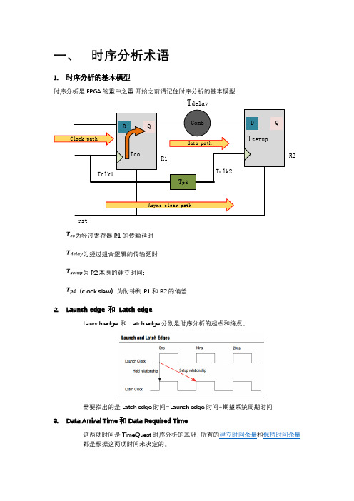
一、 时序分析术语1. 时序分析的基本模型时序分析是FPGA 的重中之重.开始之前请记住时序分析的基本模型CombT delayT pdTclk1Tclk2R1DQTcoR2D QT setupClock pathdata pathrstAsync clear path为经过寄存器R1的传输延时 为经过组合逻辑的传输延时 为R2本身的建立时间;(clock slew )为时钟到R1和R2的偏差2. Launch edge 和 Latch edgeLaunch edge 和 Latch edge 分别是时序分析的起点和终点。
需要指出的是Latch edge 时间=Launch edge 时间+期望系统周期时间3. Data Arrival Time 和Data Required Time这两项时间是TimeQuest 时序分析的基础,所有的建立时间余量和保持时间余量都是根据这两项时间来决定的。
●●需要注意的是Data Arrival Time和Data Required Time在分析不同的时序节点时,计算的公式有所差别。
4.建立时间余量Clock Setup Slack建立关系是指寄存器R1发送的数据在下一次更新(更换)之前,寄存器R2可用最短时间去锁存数据建立时间余量是指从Launch edge经过一些列延迟数据输出稳定后到Latch edge 的长度。
●Internal Register-to—Register pathsData Arrival Time= Launch Edge+ Clock Network Delay to Source Register+ tCO+Register—to-Register DelayData Required Time = Latch Edge + Clock Network Delay to Destination Register–t SU–SetupUncertainty●Input Port to Internal RegisterData Arrival Time= Launch Edge+ Clock Network Delay+ Input Maximum Delay+Port-to-Register DelayData Required Time = Latch Edge + Clock Network Delay to Destination Register–t SU–SetupUncertainty●Internal Register to Output PortData Arrival Time= Launch Edge+ Clock Network Delay To Source Register + t CO +Register—to-Port DelayData Required Time = Latch Edge + Clock Network Delay to Output Port –Output MaximumDelaytCO 指寄存器R1的自身特性tSU 指寄存器R2的自身特性如上图所示:Data Arrival Time = 启动沿时间+ Tclk1 + Tco + Tdata= 0ns + 3.2ns + 0.2ns + 0。
- 1、下载文档前请自行甄别文档内容的完整性,平台不提供额外的编辑、内容补充、找答案等附加服务。
- 2、"仅部分预览"的文档,不可在线预览部分如存在完整性等问题,可反馈申请退款(可完整预览的文档不适用该条件!)。
- 3、如文档侵犯您的权益,请联系客服反馈,我们会尽快为您处理(人工客服工作时间:9:00-18:30)。
1. Define design environment
1.1. Set_operating_conditions
1.2. Set_wire_load_model
1.3. Set_driving_cell
1.4. Set_load
1.5. Set_fanout_load
1.1. Set_max_area
1.2. set_operation_conditions
1.3. set_wire_load_model
1.4. set_ideal_*
2. Must be placed in timing fixSDCfile:
2.1. Set_clock_uncertainty,
1.6. Set_min_library
2. Set design constraints
2.1. Design rule constraints
2.1.1. Set_max_transition
2.1.2. Set_max_fanout
2.1.3. Set_max_capacitance
2.2. Design optimization constraints
[-min_phys min_proc]
[-max_phys max_proc]
[-library lib]
[-object_list objects]
[condition]
数据类型:
min_condition列表
max_conditon列表
objects列表
condition列表
参数:
-analysis_type bc_wc | on_chip_variation
Condition
指定有环境特征定义的条件,在最小最大延迟分析时使用。
描述:
该命令设定控制条件或环境特征,据此对当前设计进行时序或布局的优化。控制条件必须定义在.lib或link_library包含的任一库中。当前设计的local_link_library会被加到link_library的开头,查找时优先于link_library。库搜索顺序依次为:1. lib2. local_link_library3. link_library
描述:
该命令设置wire_load_attach_name属性给特定的端口,设计或对象列表中单元或当前设计,用于连线电容的计算。如果没有任何选项,模型将作用于顶层设计。-name选项是必须的。
如果指定的是一个设计,将作用于整个设计中的所有连线。如果指定的是一个单元,存在在当前设计中。设定给单元的连线模型会取代设计赋值给单元的连线模型。可以使用该命令设定端口外部连线负载模型,并且不受设计连线模型的影响。
[object_list]
数据类型:
model_name字符
object_list集合
参数:
-name model_name
指定连线负载模型的名称。该模型必须是已定义的。这个选项必须使用。
-library lib
指定包含模型的库。可以是一个库的名称或集合。如果是集合,工具将选择集合中首个满足条件的库。
process
浮点数代表半导体工艺特征
temperature
浮点数代表环境设定的温度
voltage
浮点数定义环境设定中电压范围的上限,下限为0.0
tree_type
环境互连模型。compile命令使用互连模式选择互连延迟的计算公式。三个有效模型:
· best_case_tree,假设连线延迟为0
· worst_case_tree,使用集中(总)RC模型
设定分析的类型。两个选项只能选择其中一个。使用bc_wc或on_chip_variation切换设计到min_max模式。bc_wc值设定最小(快)最大(慢)控制条件是两个极端的控制条件。在bc_wc分析,用最大的控制条件分析SETUP,用最小控制条件分析HOLD。on_chip_variation分析分别有最小和最大控制条件表示片上最大偏差的上下限。对所有最大延迟的路径运用最大控制条件,对所有最小延迟的路径运用最小控制条件。
· balanced_tree,所有负载均匀分摊线电阻
当工艺因素,控制温度和控制电压与标称值有偏差,compile使用线性模型补偿偏差的带来的影响,模拟为单元延迟,输入负载,输出驱动等值。包含控制条件定义的库中有标称值设计的定义。
以下例子设定控制条件为WCIND,如果link_library是my_lib.db,并且设计没有local_link_library设定。my_lib.db的库为my_lib_core。
2.2. set_max_transition
2.3. set_propagated_clock
############################################################################
set_operating_conditions:定义当前设计的控制条件
-min
指定仅用于最小延迟分析的模型。你不能用-min选项设定一个不同的模型或最小模块尺寸。因为对于这些参数,无论最大最小延迟分析都使用相同的值。
-max
指定仅用于最大延迟分析的模型。任何用于最小延迟分析的模型集都没有影响。
object_list
指定将被设定连线负载模型的端口、设计或单元的列表。连线负载模型默认设定给当前设计。
set_wire_load_model
为设计、端口、当前设计中层次化单元设定wire_load_attach_name属性,选择一个连线模型用于连线电容的计算。
语法:
status set_wire_load_model
-name model_name
[-library lib]
[-min][-max]
-min min_condition
指定用于最小延迟分析的控制条件。如果没有指定,工具默认使用最大控制条件。-min必须与-max同时使用。
-max max_condition
指定用于最大延迟分析的控制条件。
-min_library min_lib
指定用于最短延迟分析,并包含有控制条件定义的库。可以是一个库的名称或集合。如果是集合,工具将选择集合中首个满足条件的库。
指定工艺资源名称搜索相匹配的电阻和电容值,用于最大延迟分析。该选项必须与-min_phys一起使用。
-library lib
指定包含控制条件定义的库,用于最小和最大延迟分析。可以是一个库的名称或集合。如果是集合,工具将选择集合中首个包含控制条件的库。
-object_list objects
指定要设置控制条件的单元或端口。如果没有指定,默认为整个设计。该选项支持子单元或子模块。
如果没有为设计指定连线模型,首个满足条件的连线模型将默认设定给设计。当auto_wire_load_selection属性被打开,如果库有wire_load_selection表,当前设计的单元部分将自动搜索与wire_load_selection表相匹配的连线模型。如果库有不只一个表,将设置default_wire_selecting_group属性将其中一个表设定为初始表。你也可以通过set_wrie_load_selection_group进行手工设定。如果你没有使用set_wire_load_min_block_size设定模块大小,当合适的连线被选用,设计单元面积被假设为至少与这个值一样大。如果没有wire_load_selection表,库中的default_wire_load会被使用。如果上述情况都没有,将没有连线会被使用。
set_operating_conditions WCIND
控制条件’WCIND’在库”my_lib_core”中查找。
使用other_lib_core.db库中BCIND值用于最小延迟分析,WCIND用于最大延迟分析。other_lib_core.db的库名称为other_lib_core
set_operating_conditions –min BCIND –max WCIND –library other_lib_core
-max_library max_lib
指定用于最大延迟分析,并包含控制条件定义的库。可以是一个库的名称或集合。如果是集合,工具将选择集合中首个满足条件的库。
-min_phys min_proc
指定工艺资源名称搜索相匹配的电阻和电容值,用于最小延迟分析。该选项必须与-max_phys一起使用。
-max_phys max_proc
连线电阻及面积也会遵照规则考虑进连线电容的计算。
使用-min选项,你可以使用set_wire_load_model指定一个不同的连线模型用于最小延迟分析。除非明确的指定,最大最小延迟分析使用相同的连线模型。你可以设定不同的连线模型指定给设计或端口。你不可以指定不同的连线模型或模块尺寸仅用于最小延迟分析。对于这种情况,最大最小分析使用相同的值。
2.2.8. Set_max_area
3. Other commands
3.1. set_clock_groups
3.2. set_false_path
3.3. set_case_analysis
3.4. set_max_delay
1. Do not exist in timing fix SDC file:
2.2.1. create_clock
2.2.2. create_generated_clock
2.2.3. Set_clock_latency
2.2.4. Set_propagated_clock
2.2.5. Set_clock_uncertainty
2.2.6. Set_input_delay
