霍尔传感器ES2881中文手册
FSYE型使用说明书(2014最新版)

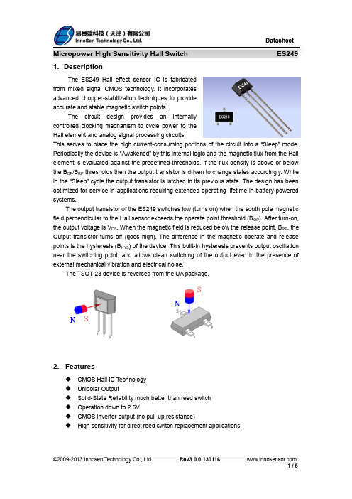
FSYE型电子称重仪表使用说明书2012年4月版●使用前请仔细阅读本产品说明书●请妥善保管本产品说明书,以备查阅长沙枫叶衡器限公司▲!安全需知1、非专业人事,请勿拆卸称重显示器。
2、传感器与称重显示器的连接必须可靠,传感器的屏蔽线必须可靠接地,连接线不允许在称重显示器通电的状态下进行插拔,防止静电损坏称重显示器或传感器。
3、传感器和称重显示器都是静电敏感设备,在使用中,必须切实采取防静电措施,严禁在秤台上进行电焊操作或其他强电操作,在雷雨季节,必须落实可靠的避雷措施,防止因雷击造成传感器和称重显示器的损坏,确保操作人员的安全和称重设备及相关设备的安全运行。
4、请确保仪器可靠接地(接地阻抗<4Ω)。
勿与其它大功率负载共同接地。
目录第一章概述................................................................................ . (1)第二章技术参数................................................................................ .. (1)第三章安装连接..................................................................... ...................... .. (2)第四章操作方法....................................................................... .... ........... (6)第五章常见故障与解决方法 (9)第六章维护保养及注意事项 (12)附录一:出厂默认参数 (13)附单 (14)第一章概述1.具有高精度、高可靠性。
2.一致性、互换性好。
3.信号抗干扰能力强:4.具有自我识别功能,便于故障诊断:5.具有较高的组秤灵活性。
霍尔传感器ES249中文手册
6. Absolute Maximum Ratings
Parameter
Supply Voltage(operating) Supply Current
©2009-2013 Innosen Technology Co., Ltd.
Symbol
VDD IDD
Value
5.5 70
Units
V μA
2/5
Symbol
VDD IDD IOUT VSAT TAW TSL
Test Conditions
Operating Average
Min
2.5
Typ
3 45 1.0
Max
5.5
Units
V μA mA
IOUT=1mA Operating Operating 20
0.4
V μS μS
600
8.
Magnetic Characteristics
24921
3 - 0.44 3.90 0.05 0.05 3.90 3 - 0.39 3.90
Active Area Depth:
3 1
0.84(Nom) 6 1
2.3. 0.1
1 2
2 1
3 4
3 1
6 1
0.5 14
Notes: 1). Controlling dimension: mm; 2). Leads must be free of flash and plating voids; 3). Do not bend leads within 1 mm of lead to package interface; 4). PINOUT: Pin 1 Pin 2 Pin 3 VDD GND Output
霍尔传感器IC分类

-
Q & A ( 3)
Q:ES2481与ES2482的区别? A:对于最新出的ES2481和ES2482两个产品,虽然名称相近,但是功能 却大不相同。 ES2481是一个单输出的产品,它可以分为ES2481H和ES2481L。 ES2481H在无磁场时输出为高,ES2481L无磁场时输出为低。 ES2482是一个双输出的产品,能同时检测N、S极,它的这一特性可以很 好的应用于玩具当中。
按输出分类(7)
微功耗霍尔IC
• 优化功耗设计的霍尔IC
风扇马达驱动霍尔IC
• 专为直流风扇设计的霍尔IC
齿轮霍尔IC
• 专为齿轮设计的霍尔IC
-
Q & A ( 1)
Q:ES495与ES49E有什么区别? A:ES495的输出是rail-to-rail输出,即霍尔IC的输出电压最高可以接近正 电源电压,最低可以低至负电源电压,该特性使得ES495的电压范围比较 广,可调空间大,被广泛应用于工业领域。 ES49E电路简单、应用普遍,大量应用与电动车调速把上。
易盛课堂
——霍尔传感器IC分类
2014.2.20
-
课题讨论安排
按工艺分类
Q&A
按输出分类
-
按工艺分类(1)
CMOS工艺
易良盛科技霍尔传感器IC可以分为:
Bipolar工艺
CMOS工艺
• 霍尔IC器件内部集成了上百个甚至上千个场效应管
A:霍尔传感器常常指一个比较大一点的模块,霍尔IC或霍尔元件只是
它其中的一部分; 霍尔元件只是根据霍尔效应集成的一个敏感元件,是复合材料; 霍尔IC是Si制作,集成了霍尔敏感元件和少量简单处理的电路。
-
霍尔接近开关使用说明书
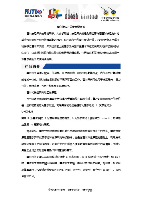
霍尔接近开关使用说明书霍尔接近开关使用说明书。
大家都知道,接近开关就是利用位移传感器对接近物体的敏感特性达到控制开关通或断的目的,现在流行一种霍尔接近开关,它的原理就是当磁性物件移近霍尔开关时,开关检测面上的霍尔元件因产生霍尔效应而使开关内部电路状态发生变化,由此识别附近有磁性物体控制开关的通或断。
今天南京凯基特就来给大家介绍一下霍尔接近开关使用说明书。
霍尔开关具有无触电、低功耗、长使用寿命、响应频率高等特点,内部采用环氧树脂封灌成一体化,所以能在各类恶劣环境下可靠的工作。
霍尔开关可应用于接近开关,压力开关,里程表等,作为一种新型的电器配件。
霍尔式接近开关的工作原理当一块通有电流的金属或半导体薄片垂直地放在磁场中时,薄片的两端就会产生电位差,这种现象就称为霍尔效应。
两端具有的电位差值称为霍尔电势U,其表达式为U=K·I·B/d其中K为霍尔系数,I为薄片中通过的电流,B为外加磁场(洛伦磁力Lorrentz)的磁感应强度,d是薄片的厚度。
由此可见,霍尔效应的灵敏度高低与外加磁场的磁感应强度成正比的关系。
霍尔效应原理图霍尔开关就属于这种有源磁电转换器件,它是在霍尔效应原理的基础上,利用集成封装和组装工艺制作而成,它可方便的把磁输入信号转换成实际应用中的电信号,同时又具备工业场合实际应用易操作和可靠性的要求。
霍尔开关的输入端是以磁感应强度B来表征的,当B值达到一定的程度(如B1)时,霍尔开关内部的触发器翻转,霍尔开关的输出电平状态也随之翻转。
输出端一般采用晶体管输出,和接近开关类似有NPN、PNP、常开型、常闭型、锁存型(双极性)、双信号输出之分。
它的主要特性参数有以下几类。
(1)输入电阻霍尔传感器元件两激励电流端的直流电阻称为输入电阻。
它的数值从几欧到儿百欧,视不同型号的元件而定。
温度升高,输入电阻变小,从而使输入电流变大,最终引起霍尔传感器电势变化。
为了减少这种影响,最好采用恒流源作为激励源。
霍尔传感器中文手册

1.描述ES582是单极霍尔效应传感器从混合信号IC制造CMOS技术。
设备集成了一个电压调节器,霍尔传感器动态补偿取消系统,施密特触发器和一个open-drain输出驱动程序,所有在一个包中。
它集成了先进的直升机稳定技术提供准确和稳定的磁开关点。
有很多申请这HED -霍尔电子设备除了那些下面列出。
由于其宽工作电压范围和扩展温度范围的选择,它非常适用于汽车,工业和消费者应用程序。
交付的设备是在一个小提纲晶体管(说)表面安装过程和在一个塑料单(- 92平)通孔。
3-lead 包都是通过无铅认证。
2.特性宽工作电压范围3.5 v和24 v介质的敏感性CMOS技术Chopper-stabilized放大级优良的温度稳定性极低的开关点漂移对身体压力低电流消耗明渠输出小SOT23 3 l和平板- 92 3 l,通过无铅认证包3.应用程序汽车、消费品和工业固态开关断续器速度检测线性位置检测角位置检测接近detectio4.原理框图5.术语表术语描述毫伏特斯拉(mT) 高斯,磁通密度单位:1吨= 10高斯 RoHS有害物质限制SOT 小轮廓晶体管(说包)——也被称为包代码” ESD 静电放电 BLDCBrush-Less 直流操作点(BOP)磁通密度应用于品牌的包将输出驱动程序(输出电压= VDSon)释放点(BRP)磁通密度应用于品牌的包挫伤了驱动程序的输出(输出电压=高)6.销的定义和描述SE 销UA 销.类型函数名称 1 1 V DD 输入 电源电压销 2 3 OUT 输出 输出销 32GND接地地面销VDDOUTV oltage Regulat o rChopperHall PlateGNDUA Package SO Package Pin 1 – V DDPin 1 – V DDPin 2 – GND P in 2 – OUT Pin 3 – OUT P in 3 – GND7.独特的特性基于混合信号CMOS技术,Innosen ES582霍尔设备与介质磁敏感性。
CTEK SWEDEN AB ESES 21 新型专业电池充电器用户手册说明书

E SETAPA 1 DESULFATACIÓNDetecta las baterías sulfatadas. Corrientes y tensiones pulsantes eliminan los sulfatos de las placas de plomo de la batería y restablecen su capacidad.ETAPA 2 INICIO SUAVEComprueba si la batería puede aceptar la carga. Esta etapa impide que continúe el proceso de carga si la batería está defectuosa.ETAPA 3 VOLUMENCarga con corriente máxima hasta aproximadamente el 80% de la capacidad de la batería.ETAPA 4 ABSORCIÓNCarga con corriente decreciente para maximizar hasta el 100% la capacidad de la batería.ETAPA 5 ANÁLISISComprueba si la batería puede retener la carga. Las baterías que no pueden retener la carga quizás deberán ser reemplazadas.ETAPA 6 REGENERACIÓNSeleccionar el programa Recond para agregar la etapa de regeneración al procesode carga. Durante la etapa Recond, la tensión aumenta para generar en la batería un desprendimiento controlado de gases. El gas emitido se combina con el ácido de la batería y hacer recuperar energía a la misma.ETAPA 7 FLOTANTEMantiene la tensión de la batería al nivel máximo mediante carga a tensión constante. ETAPA 8 PULSOSMantiene la batería al 95–100 % de su capacidad. El cargador monitorea la tensión de la batería y da un pulso cuando es necesario para mantener la batería completamente cargada.E SETAPA 1 ENCENDIDOLea la sección sobre baterías con “protección frente a bajas tensiones” en la página anterior.ETAPA 2 ADMISIÓNComprueba si la batería puede aceptar la carga. Esta etapa impide que continúe la carga si la batería está defectuosa.ETAPA 3 CARGA DE VOLUMENCarga con corriente máxima hasta aproximadamente el 90 % de la capacidad de la batería.ETAPA 4 ABSORCIÓNCarga con corriente decreciente para maximizar hasta el 100% la capacidad de la batería.ETAPA 5 ANÁLISISComprueba si la batería puede retener la carga. Podría ser necesario cambiar las baterías que no pueden retener la carga.ETAPA 6No aplicable.ETAPA 7 FLOTANTEMantiene la tensión de la batería al nivel máximo mediante carga a tensión constante. ETAPA 8 PULSOSMantenimiento de la batería al 95-100 % de su capacidad. El cargador controla la tensión de la batería y suministra un pulso para mantener la batería completamente cargada.LISTA PARA USOLa tabla muestra el tiempo estimado para cargar al 80% una batería descargada. TAMAÑO DE BATERÍA (Ah)TIEMPO HASTA EL 80% DE CARGA 5Ah2h10Ah4h15Ah6h20Ah7h25Ah9hESPECIFICACIONES TÉCNICASNúmero de modelo1087Tensión nominal CA220–240VAC, 50–60HzTensión de carga14,4V, 15,8V, 14,2VTensión de batería mín.Plomo: 2,0V, Litio: 5,0VCorriente de carga2,3A máx.Corriente, red0,6A rms (a plena corriente de carga)Pérdidas de contracorriente*< 1,5Ah/mesTensión de ondulación**<4%Temperatura ambiente-20°C a +50°CTipo de cargador De ocho etapas, ciclo de cargacompletamente automáticoTipos de batería Todos los tipos de baterías de plomo de 12 V (WET, MF,Ca/Ca, AGM, GEL)Baterías de litio 12 V (4 celdas) (LiFePO4, LiFe, Li-iron,LFP)Capacidad de batería 5 a 25AhDimensiones168 x 65 x 38 mm (Long. x Anch. x Alt.)Clase de aislamiento IP65Peso0,6kg*) La pérdida de contracorriente es la corriente que se pierde si el cargador no está conectado a la red. Los cargadores CTEK tienen una contracorriente muy baja.**) La calidad de la tensión de carga y de la corriente de carga son muy importantes. Una corriente de ondulación alta calienta la batería, lo cual tiene un efecto de envejecimiento en el electrodo positivo. Una tensión de ondulación alta puede dañar a otro equipo que esté conectado a la batería. Los cargadores de batería CTEK producen una tensión muy limpia y una corriente con una ondulación baja.GARANTÍA LIMITADACTEK SWEDEN AB, expide la presente garantía limitada al comprador original de este producto. Esta garantía limitada no es transferible. La garantía rige para defectos de fabricación y material durante 5 años a partir de la fecha de compra. El cliente debe devolver el producto junto con el recibo de compra al punto de compra. Esta garantíano es válida si el cargador de baterías se ha abierto, manejado descuidadamente o reparado por otros que no sean CTEK SWEDEN AB o sus representantes autorizados. Uno de los agujeros de tornillo en el fondo del cargador está sellado. La supresión o deterioro del sellado invalidará la garantía. CTEK SWEDEN AB no concede otra garantía que esta garantía limitada y no se hace responsable de otros costos que los arriba mencionados, es decir, no se hace responsable de daños consecuenciales. Además, CTEK SWEDEN AB no está obligada a otra garantía que la presente.ASESORAMIENTOCTEK ofrece asesoramiento profesional a los clientes: .Para la última revisión del manual vea . Por correo electrónico:************, por teléfono: +46(0) 225 351 80, por fax +46(0) 225 351 95.52345B。
CYHP881霍尔探头用户手册说明书
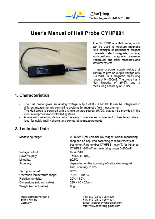
Tel.: +49 (0)8121-2574100 Markt Schwabener Str. 8User’s Manual of Hall Probe CYHP8811. Characteristics- The Hall probe gives an analog voltage output of 0 - 4.5VDC. It can be integrated indifferent measuring and controlling systems for magnetic field measurement.- The Hall probe is powered with a single voltage source +5VDC that can be provided in themost microprocessor controlled systems.- A low-cost measuring device, which is easy to operate and convenient to handle and store. - Ideal for quick quality checks and comparative measurements2. Technical DataMeasuring range:0 - 500mT (for unipolar DC magnetic field, measuring rang can be adjusted according to requirements of customer. Part number CYHP881-xxxmT, for instance, CYHP881-200mT for measuring range 0-200mT) Voltage output: 0 - 4.5VDCPower supply: +5VDC (± 10%) Linearity: ±0.5%Accuracy: depending on the accuracy of calibration magnet field, normally ±1.0% Zero point offset:0.2%Operation temperature range: -40°C ~ +85°C Relative humidity: 20% ~ 80%Dimensions (without cable): 220 x 40 x 26mm Weight (without cable):80gTel.: +49 (0)8121-2574100 Markt Schwabener Str. 83. Connection4. FunctionsThe CYHP881 can be used to measure the magnetic field by putting the head of the Hall probe on the surface of the measured magnet or at the measuring point of a magnetic field. The magnetic lines of the measured magnetic field should perpendicularly pass through the Hall Effect element of the Hall probe.By increasing the magnetic field, a linear behavior at the voltage output should be visible.Tel.: +49 (0)8121-2574100 Markt Schwabener Str. 8Moreover, the sensor head is smoother and there are no numbers or letters on the front side of the Hall chip.On the rear side of the Hall probe, there are potentiometers for adjusting the zero offset and gain.The zero offset can be adjusted by the potentiometer named with “Offset”. It is recommended to set up a zero point at about 8mV, which means a zero point deviation of about 0.2%. By using this method, a dead zone, which causes decreasing sensitivity and nonlinear behavior, can be avoided effectively.Sometimes it is necessary to adjust the output voltage for the proper usage at a certain magnetic field level. This can be done by setting up the correct gain factor with the “Gain” potentiometer.Tel.: +49 (0)8121-2574100 Markt Schwabener Str. 85. Calibration dataThe calibration is processed with a Gaussmeter CYHT201 for measuring magnetic field strength generated from an electromagnet and an Agilent 34401a multimeter for measuring the output voltage of the probe CYHP881-200mT at the magnetic field.- Calibration results by using magnetic field generated by an electromagnet(theoretical voltage output at 198.8mT: 4.473V)- Precise calibration points by using Alnico reference permanent magnet (theoretical voltage output at 178mT: 4.005V)6. Application- Measuring magnetic field strength of permanent magnet materials, electromagnets, motors, loudspeakers, magnetic sensors/transducer and other machines and instruments etc.- Magnetic field measurement by integrating in measuring instruments and controlling systems.- Magnetic field measurement together with any digital voltmeters, ADC and other voltage measuring instruments etc.7. Attention- Please be careful with the head of the Hall probe. Use the protection cover for avoiding any damage of the sensor head after using the probe.- The probe doesn’t give any output signal if one put s the front side to the surface of the measured magnet.- It is recommended to set up a zero point at about 8mV for avoiding any dead zone which decreases the sensitivity and shows nonlinear behavior.- Please do not open the case in order to avoid any damage and malfunction on the Hall probe.8. WarrantyChenYang Technologies GmbH & Co. KG warrants its products against defects in workmanship and materials under normal use and service for a period of 12 months from the shipping date. All obligations and liabilities under this warranty are limited to repairing or replacing at our option.The warranty is extended only to the original purchaser. The warranty shall not apply to any products or parts which have been damaged on account of improper installation, improper connections, misuse, neglect, accident or abnormal conditions of operation.Any attempt to tamper with the products as evidenced by disruption of warranty sticker and/or unauthorised repair/modification of the products shall render this warranty null and void.Markt Schwabener Str. 8Tel.: +49 (0)8121-2574100。
常闭型全极霍尔YS2481中文产品手册

YS2481
注意事项
1.霍尔是敏感器件,在使用过程以及存储过程中请注意采取静电防护措施。
2.霍尔在安装过程中应尽量避免对霍尔本体施加机械应力,如管脚需要弯曲请在距引线根部3MM 以外操作。
3.建议焊接温度:电烙铁焊接,建议温度350℃,最长5秒。
波峰焊:建议最高温度260℃,最长3秒红外回流焊:建议最高245℃,最长10秒
4.不建议超越数据表中的参数使用,虽然极限参数下霍尔会正常工作,但是长时间处于极限条件下可能会造成霍尔或者实际产品的损坏,为了保障霍尔的正常工作和产品的安全性稳定性,请在数据表许可范围内使用。
- 1、下载文档前请自行甄别文档内容的完整性,平台不提供额外的编辑、内容补充、找答案等附加服务。
- 2、"仅部分预览"的文档,不可在线预览部分如存在完整性等问题,可反馈申请退款(可完整预览的文档不适用该条件!)。
- 3、如文档侵犯您的权益,请联系客服反馈,我们会尽快为您处理(人工客服工作时间:9:00-18:30)。
Release Point (BRP)
Descriptions
Gauss, Units of magnetic flux density: 1mT = 10 Gauss Restriction of Hazardous Substances Small Outline Transistor (SOT package) – also referred with the package code “SO” Electro-Static Discharge Brush-Less Direct-Current Magnetic flux density applied on the branded side of the package which turns the output driver ON (VOUT = VDSon) Magnetic flux density applied on the branded side of the package which turns the output driver OFF (VOUT = high)
©2009-2013 Innosen Technology Co., Ltd.
Rev3.0.0.130124
2 / 10
Datasheet
Very High Sensitivity Hall Latch 7. Detailed General Description
ES2881
switch points. There are many applications for this sensor in addition to those listed above. The design, specifications and performance have been optimized for commutation applications in 5V and 12V brushless DC motors. Thanks to its wide operating voltage range and extended choice of temperature range, it is quite suitable for use in automotive, industrial and consumer applications. The device is delivered in a Small Outline Transistor (SOT) for surface mount process and in a Plastic Single In Line (TO-92 flat) for through- hole mount. Both 3-lead packages are RoHS compliant.
2. Features
Wide operating voltage range from 3.5V to 24V High magnetic sensitivity – Multi-purpose CMOS technology Chopper-stabilized amplifier stage Superior temperature stability Extremely low switchpoint drift Insensitive to physical stress
VDD
Voltage Regulator
ES2881
OUT
Chopper
Hall Plate
GND
UA Package Pin 1 – VDD Pin 2 – GND Pin 3 – OUT SO Package Pin 1 – VDD Pin 2 – OUT Pin 3 – GND
5. Glossary of Terms
ES2881
The ES732 exhibits latch magnetic switching characteristics. Therefore, it requires both south and north poles to operate properly. The OUT pin of these devices switches low (turns on) when a magnetic field perpendicular to the Hall sensor exceeds the operate point threshold, BOP. After turn-on, the output voltage is VDSon. Note that the device latches, that is, a south pole of sufficient strength towards the branded surface of the device turns the device on. The device remains on if the south tching property defines the device as a magnetic memory. When the magnetic field is reduced below the release point, BRP, the OUT pin turns off (goes high). The difference in the magnetic operate and release points is the hysteresis, BHYS, of the device. This built-in hysteresis prevents output oscillation near the switching point, and allows clean switching of the output even in the presence of external mechanical vibration and electrical noise. The device behaves as a latch with symmetric operating and release switching points (BOP=|BRP|). This means magnetic fields with equivalent strength and opposite direction drive the output high and low. Powering-on the device in the hysteresis region (less than BOP and higher than BRP) allows an indeterminate output state. The correct state is attained after the first excursion beyond B OP or BRP. The SOT-23 device is reversed from the UA package. The SOT-23 output transistor will be latched on in the presence of a sufficiently strong North pole magnetic field applied to the marked face.
UA package - Latch characteristic
SO package
- Latch characteristic
8. Unique Features
Based on mixed signal CMOS technology, InnoSen ES2881 is a Hall-effect device with high magnetic sensitivity. This multi-purpose latch suits most of the application requirements. The chopper-stabilized amplifier uses switched capacitor technique to suppress the offset generally observed with Hall sensors and amplifiers. The CMOS technology makes this advanced technique possible and contributes to smaller chip size and lower current
6. Pin Definitions and Descriptions
SE Pin No.
1 2 3
UA Pin No.
1 3 2
Name
VDD OUT GND
Type
Supply Output Ground
Function
Supply Voltage Pin Open Drain Output Pin Ground Pin
Low current consumption Open drain output Tiny SOT23 3L and flat TO-92 3L, both are RoHS Compliant packages
3. Applications
Automotive, Consumer and Industrial Solid-state switch Brushless DC motor commutation Speed detection Linear position detection Angular position detection Proximity detection