约克螺杆机控制线路图(原版)
YORK 约克YEWS-HP满液式水地源热泵螺杆-R134a

YEWS-HP系列
综合的专业化服务, 专为您的业务需求量身定制 我们关注您的业务需求, 了解每个 行业有其独特的要求。我们全方位 的维护服务能满足您在经济和技术 方面的所有需求, 包括日常设备检 查和预测性维护常规工作以及系统 性能检测和每年的停工检修等。
水/地源热泵系统应用
YEWS-HP型水/地源热泵机组
YEWS-HP水/地源热泵机组为江森自控最新开发的产品,采用高效、工业用、专 为水/地源热泵开发的半封闭双螺杆压缩机,制冷剂为HFC-134a,优质可靠,能 效比极高,寿命长。
采用高效满液式蒸发器,大大提高机组效率,COP值居行业前列。
高效压缩机能在最小负荷位置启动,通过一连续作用的滑阀,可以在100%~25%的 负荷范围内进行容量调节,保证压缩机效能完全发挥,令部分负荷效能大大提高。
压缩机
每台压缩机都是直接传动、半封闭双螺杆式,并包括 下列部件:
锻钢制造的双螺杆转子,采用专为HFC-a制冷剂 开发的转子型线。 精密加工的压缩机铸铁机体,为转子提供最佳的余隙。 整台压缩机的设计压力为.MPa表压,内置安全阀 的起跳压力为.0Mpa。 容量控制:压缩机在最小负荷位置启动,受微处 理器控制的容量调节阀通过一连续作用的滑阀在 00%~%负荷范围内实现无级调节。 容量调节阀的弹簧自动复位到最小负荷位置,以确 保压缩机电机在最小负荷下启动。 内置油加热器确保合适的油温。 内部排气止回阀可以防止转子在停机时逆转。 排气截止阀。 防水接线盒。 吸气冷却、高效可靠的半封闭式电机具有过载保 护:热敏电阻保护。 跟直接启动相比,星三角压缩机电机启动器使启动 电流大约降至% (工厂安装)。 专为水/地源热泵工况设计
点阵液晶,可显示×个中文字符。 轻触式键盘,分为功能键和编程键两个区。 标准控制器包括:机组报警触点、冷冻泵控制、断电 后自动复位、按运行工况对系统进行自动优化。 软件存储在非易失存储器 (FLASH ROM)中以免机组因 交流电源断电而发生故障。 程序设定值保存在EPROM存储器中。
约克螺杆式冷水机组
6. 风机段
Ⅰ.风机(空气处理机主要使用离心风机) a.离心风机按驱动形式可以分成: 皮带轮驱动
式、直联式。
皮带轮 锥套
V型皮带
皮带调节螺栓
皮带轮驱动式
直联式: 其中外转子式、无蜗壳风机也可以算作直联式 的一种。
无蜗壳直联式
直联式
外转子式
末端设备—风机盘管
2 3
1
1 4
2 3
4
风机盘管控制系统原理图
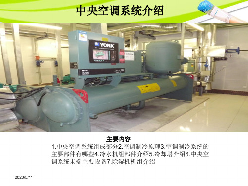
中央空调系统介绍
主要内容 1.中央空调系统组成部分2.空调制冷原理3.空调制冷系统的 主要部件有哪些4.冷水机组部件介绍5.冷却塔介绍6.中央空 调系统末端主要设备7.除湿机机组介绍
2013-7-10
一、中央空调工作系统图
2013-7-10
二、空调制冷系统流程图
气体 高温 高压 压缩机
油分离器 把制冷剂 和润滑油 分离
四、冷水机组部件—控制中心
开/关
冷水机组部件—水流开关
冷水机组部件—安全阀
冷水机组—制冷剂视镜
冷水机组部件—制冷剂注入口
制冷剂注入口
五、冷却塔
• 冷却塔是水与空气直 接接触进行热交换的 一种设备, • 它主要由风机、电机、 填料、播水系统、塔 身、水盘等组成, • 主要由在风机作用下 的温度比较低的空气 与填料中的水进行热 交换从而达到降低水 温的目的
2013-7-10
80% , 粒子直径 5μm
板式过滤器分为可清洗和 褶形板式一次性过滤器。
中效过滤段
滤网标准配置为袋式,有板
式可供选择。 净化空调:过滤级别为 F6,F7,F8(30万级),大气层计数效 率:40-90% 粒子直径1μm
也可采用密褶式中效过滤器
约克资料(冷水机组接线)
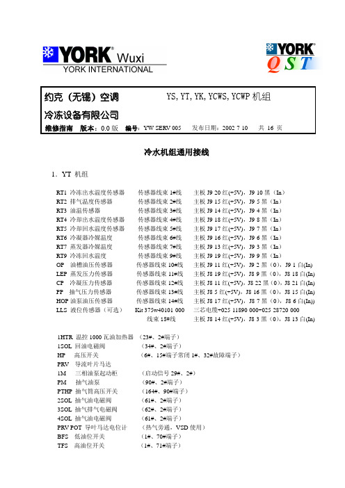
约克(无锡)空调YS,YT,YK,YCWS,YCWP机组冷冻设备有限公司维修指南版本:0.0版编号:YW-SERV-005 发布日期:2002-7-10 共16 页冷水机组通用接线1.YT 机组RT1 冷冻出水温度传感器传感器线束1#线主板J9-20红(+5V),J9-10黑(In)RT2 排气温度传感器传感器线束2#线主板J9-15红(+5V),J9-5黑(In)RT3 油温传感器传感器线束3#线主板J9-14红(+5V),J9-4黑(In)RT4 冷却出水温度传感器传感器线束4#线主板J9-18红(+5V),J9-8黑(In)RT5 冷却回水温度传感器传感器线束5#线主板J9-17红(+5V),J9-7黑(In)RT6 冷凝器冷媒温度传感器线束6#线主板J9-16红(+5V),J9-6黑(In)RT7 蒸发器冷媒温度传感器线束7#线主板J9-13红(+5V),J9-3黑(In)RT9 冷冻回水温度传感器线束9#线主板J9-19红(+5V),J9-9黑(In)OP 油槽油压传感器传感器线束10#线主板J9-11红(+5V),J9-2黑(0),J9-1白(In) LEP 蒸发压力传感器传感器线束11#线主板J8-19红(+5V),J8-9黑(0),J8-18白(In) CP 冷凝压力传感器传感器线束12#线主板J8-11红(+5V),J8-22黑(0),J8-21白(In) PP 抽气压力传感器传感器线束13#线主板J8-5红(+5V),J8-16黑(0),J8-15白(In) HOP油泵油压传感器传感器线束14#线主板J8-17红(+5V),J8-7黑(0),J8-6白(In)) LLS 液位传感器(可选)Kit 375w40101-000 三芯电缆+025-11890-000+025-28720-000线束15#线主板J8-14红(+5V),J8-3黑(0),J8-13白(In) 1HTR 温控1000瓦油加热器(23#、2#端子)1SOL 回油电磁阀(34#、2#端子)HP 高压开关(6#、15#端子常闭1#、32#故障端子)PRV 导流叶片马达1M 三相油泵起动柜(启动信号29#、2#)PM 抽气油泵(90#、2#端子)PTHP 抽气筒高压开关(164#、90#端子)2SOL 抽气油电磁阀(61#、2#端子)3SOL 抽气排气电磁阀(62#、2#端子)4SOL 抽气油电磁阀(61#、2#端子)PRV POT 导叶马达电位计(热气旁通,VSD使用)BFS 低油位开关(1#、70#端子)TFS 高油位开关(1#、71#端子)VMS 限位开关(1#、18#端子)2.YS机组RT1 冷冻出水温度传感器传感器线束1#线主板J9-20红(+5V),J9-10黑(In)RT2 排气温度传感器传感器线束2#线主板J9-15红(+5V),J9-5黑(In)RT3 油温传感器传感器线束3#线主板J9-14红(+5V),J9-4黑(In)RT4 冷却出水温度传感器传感器线束4#线主板J9-18红(+5V),J9-8黑(In)RT5 冷却回水温度传感器传感器线束5#线主板J9-17红(+5V),J9-7黑(In)RT7 蒸发器冷媒温度传感器线束7#线主板J9-13红(+5V),J9-3黑(In)RT9 冷冻回水温度传感器线束9#线主板J9-19红(+5V),J9-9黑(In)FOP 油过滤器压力传感器传感器线束10#线主板J9-11红(+5V),J9-2黑(0),J9-1白(In) EP 蒸发压力传感器传感器线束11#线主板J8-19红(+5V),J8-9黑(0),J8-18白(In) CP 冷凝压力传感器传感器线束12#线主板J8-11红(+5V),J8-22黑(0),J8-21白(In) POT 滑阀电位计传感器线束13#线主板J8-12红(+5V),J8-2黑(0),J8-1白(In) OP 油压传感器传感器线束14#线主板J8-17红(+5V),J8-7黑(0),J8-6白(In)) SOP 轴封油压传感器传感器线束15#线主板J8-5红(+5V),J8-16黑(0),J8-15白(In)1SOL 油路电磁阀(62#、2#端子)2SOL 液相电磁阀(29#、2#端子)1HTR 温控500瓦油加热器(28#、2#端子温控开关64#、28#)SOLS 油位开关(1#、18#正常闭合)aSOL 滑阀卸载(58#、2#)bSOL 滑阀上载(4#、2#)HP 高压开关(6#、15#常闭,1#、30#故障)3.YK机组RT1 冷冻出水温度传感器传感器线束1#线主板J9-20红(+5V),J9-10黑(In)RT2 排气温度传感器传感器线束2#线主板J9-15红(+5V),J9-5黑(In)RT3 油温传感器传感器线束3#线主板J9-14红(+5V),J9-4黑(In)RT4 冷却出水温度传感器传感器线束4#线主板J9-18红(+5V),J9-8黑(In)RT5 冷却回水温度传感器传感器线束5#线主板J9-17红(+5V),J9-7黑(In)RT6 冷凝器冷媒温度传感器线束6#线主板J9-16红(+5V),J9-6黑(In)RT7 蒸发器冷媒温度传感器线束7#线主板J9-13红(+5V),J9-3黑(In)RT9 冷冻回水温度传感器线束9#线主板J9-19红(+5V),J9-9黑(In)OP 油槽油压传感器传感器线束10#线主板J9-11红(+5V),J9-2黑(0),J9-1白(In) LEP 蒸发压力传感器传感器线束11#线主板J8-19红(+5V),J8-9黑(0),J8-18白(In) CP 冷凝压力传感器传感器线束12#线主板J8-11红(+5V),J8-22黑(0),J8-21白(In) 近程式传感探头传感器线束13#线J8-12棕(+5V),J8-2黑(0),J8-15兰(In),红(+24V) HOP泵油压传感器传感器线束14#线主板J8-17红(+5V),J8-7黑(0),J8-6白(In)) LLS 液位传感器传感器线束15#线主板J8-14红(+5V),J8-3黑(0),J8-13白(In) 变频油泵驱动传感器线束19#线主板J20-1白(PWM),J20-2红(+12),J20-3黑(En)OV A POT节流孔板电位计传感器线束21#线主板J7-12红(+5V),J7-24黑(0),J7-23白(In)1HTR 温控3000瓦三相油加热器(温控端子34#、107#,接触器端子107#、2#)1SOL 回油电磁阀(61#、2#)HP 高压开关(正常6#、15#常闭,故障1#、32#)OV A 节流孔板执行器PRV 导流叶片马达关键部件功能及接线1.Control panel由主板、I/O板、电源、显示器、键盘及CM-2板(机电式启动用)或ACCB(自适应容量控制板,VSD用)组成。
约克螺杆式冷水机组YS系列样本图册

状态信息包括: - 系统准备启动 - 正常停机-自动重启 - 紧急停机-手动重启 - 开机程序被启动 - 系统正在运行 - 禁止启动 - 滑阀在关机前关闭 - 系统锁定延时 - 控制冷冻水出水 - 电机-降温需求限制 - 电机-高电流限定 - 防再循环XX分钟/秒 - 滑阀位置>0% - 电机电流>1%FLA
的运行参数与机组运行状态。
高效热交换器,表现卓越
热交换器采用了最新的高效换热铜管,使传热效率最佳、结构紧凑。水侧和制冷
剂侧强化传热,减少机组能耗和管道结垢。
双螺杆压缩机,高效可靠
采用世界著名品牌的工业用双螺杆压缩机,效率极
高,安全可靠。
结构紧凑,安装方便
机组设计精密紧凑,大大减少机房占地面积。安装时只需少量的接管和布线,减
可以在远程位置用触点闭合信号或通过串行通信来更改设定值。远程重设范围可 调(达11.1℃),可以按重设的需要来灵活、有效地使用远程信号。约克ISN楼宇自 动化系统(BAS)通过专用通讯接口,通讯协议为Modbus RTU。
智能防冻保护使冷水机组能在2.2℃的冷冻水出口温 度下运行,当水温过低时机组不会出现干扰跳闸。复 杂的程序和传感器将监控冷水机组的水温,以免结 冰。每个可编程点都给出了容许范围,禁止在设计极 限之外对冷水机组编程。
智能防冻 - 蒸发器-压力传感器或
出水温度探头 - 蒸发器-压力传感器或
温度传感器 - 冷凝器-高压保护触点
断开 - 冷凝器-压力过高 - 冷凝器-压力传感器超
出量程
- 辅助安全停机- 触点闭合
- 排气-温度过高 - 排气-温度过低 - 润滑油-温度过高 - 润滑油-压差过小 - 润滑油-密封圈压差
YS型标准冷水机组具有最大的灵活性,设定了两个不 同的低水温再启动限制值,可以方便地在标准和蓄冰 两种模式下切换,避免了不必要的周期性停机。
约克螺杆机控制线路图(原版)
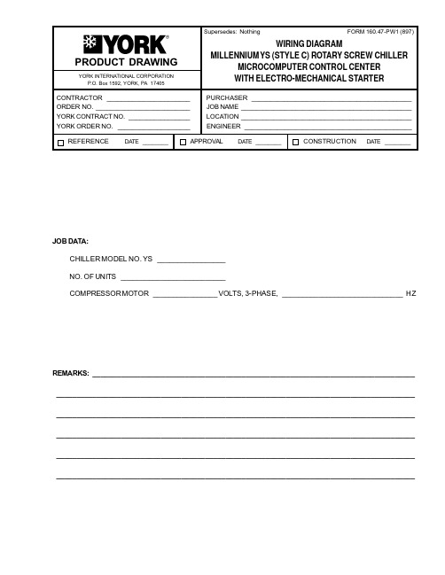
PRODUCT DRAWINGYORK INTERNATIONAL CORPORATIONP .O. Box 1592, YORK, PA 17405CONTRACTOR _______________________PURCHASER ____________________________________________ORDER NO.__________________________JOB NAME _______________________________________________YORK CONTRACT NO._________________LOCATION _______________________________________________YORK ORDER NO.____________________ENGINEER ______________________________________________REFERENCEDA TE ________APPROVAL DA TE ________CONSTRUCTION DATE ________Supersedes: Nothing WIRING DIAGRAMMILLENNIUM Y S (STYLE C) ROTARY SCREW CHILLERMICROCOMPUTER CONTROL CENTER WITH ELECTRO-MECHANICAL STARTERJOB DATA:CHILLER MODEL NO. YS _________________NO. OF UNITS __________________________COMPRESSOR MOTOR ________________VOLTS, 3-PHASE,______________________________H ZREMARKS:_____________________________________________________________________________________________________________________________________________________________________________________________________________________________________________________________________________________________________________________________________________________________________________________________________________________________________________________________________________________________________________________________________________FORM 160.47-PW1 (897)ELEMENTARY DIAGRAMREF. 035-09973-000, REV D(Cont d. on pages 3 & 4)LD023992 YORK INTERNATIONALFORM 160.47-PW13YORK INTERNATIONALELEMENTARY DIAGRAMLD02400LD02401TIMING DIAGRAMELEMENTARY DIAGRAM (Cont d.)4YORK INTERNATIONALFORM 160.47-PW15YORK INTERNATIONALLD02403ELEMENTARY DIAGRAM (Cont d.)NOTES:1.This wiring diagram describes the standard electroniccontrol scheme for use with an Electro-Mechanical Starter. For details of standard modifications (by oth-ers), refer to Product Drawing Form 160.47-PW5.2.Field wiring to be in accordance with the NationalElectrical Code as well as all other applicable codes and specifications. See Product Drawing Form 160.47-PW3 for field wiring connections.3.Numbers along the left side of diagram are line iden-tification numbers. The numbers along the right side indicate the line number location of relay contacts.An underlined contact location signifies a normally closed contact.4.Main control panel Class 1 field wiring terminal con-nection points are indicated by numbers within a rect-angle, i.e. 15 . Main control panel factory wiring terminal connection points are indicated by numbers within a triangle, i.e. 5 . Component terminal markings are indicated by numbers within a circle, i.e.C1 . Numbers adjacent to circuit lines are the circuit identification numbers.5.To cycle on and off automatically with contacts otherthan those shown, install a cycling device between terminals 1 & 13 (line 27) (see Note 9). If a cycling device is installed, jumper must be removed between terminals 1 & 13 .pressor motor starter with starter interlock con-tacts (rated 0.2 amps @ 120 volts A.C.) must be per Form 160.47-PW7. Control panel shall be grounded.7.Units installed in Canada must have a field suppliedCSA approved 30 amp disconnect switch and a 15 amp dual element fuse mounted external to control panel for 115 volt control supply.8.To stop unit and not permit it to start again, install astop device between terminals 1 & 8 (line 23) (see Note 9). A Remote start-stop switch may beconnected to terminals 1 , 7 & 8 (lines 22 and23) (see Note 9). Remote start-stop switch (line 22)is operative only in the remote operating mode.9.Device contact rating to be 5 miliamperes at 115 voltsA.C.10.Contact rating is 5A resistive @ 120 volts A.C. or240 volts A.C.11.To check motor rotation on initial start-up, install mo-mentary switch between terminals 24 & 25 (line35). Depress start switch, after approx. 30 seconds,jog motor with momentary switch. When proper rota-tion is obtained, replace momentary switch with jumper. Switch must have a minimum contact rating of 2 FLA, 10 LRA at 115 volts A.C.12.Solid state motor overload (CM) is set to trip at 105%FLA. During momentary power interruption (power fault), contact also opens for 1 second.13.For high and low voltage units, the factory suppliedjumper between 1 & 53 must be removed when Electro-Mechanical starter overloads and/or safety devices are used. For high voltage (2300-4160) UL and CSA approved units only, electro-mechanical compressor motor starter overloads (normally closed) must be connected between 1 & 53 .14.Contact rating is 5 amps resistive @ 250 volts A.C.& 30 volts D.C., 2 amp inductive (0.4 PF) @ 250 volts A.C. & 30 volts D.C.15.Each 115VAC field-connected inductive load, i.e. re-lay coil, motor starter coil, etc. shall have a transient suppressor wired in parallel with its coil, physically located at the coil. Spare transient suppressors and control circuit fuses are supplied in a bag attached to the top of the hinged panel.16.Low oil pressure (LOP) safety shutdown occurs whenoil pressure evaporator pressure differential is less that 15 psi following a 3 minute bypass at compres-sor start.LEGENDLD024026 YORK INTERNATIONALFORM 160.47-PW17YORK INTERNATIONALPRESSURE TEMPERATURE CHARTLD02404* Function provided by condenser transducerCONNECTION DIAGRAM8YORK INTERNATIONALFORM 160.47-PW19YORK INTERNATIONALCONNECTION DIAGRAMLD02405CONNECTION DIAGRAM (Cont d)10YORK INTERNATIONALFORM 160.47-PW111YORK INTERNATIONAL LD02406CONNECTION DIAGRAM (Cont d)P.O.Box1592,YORK,Pennsylvania USA17405-1592Subject to change without notice.Printed in USA Copyright©by YORK International Corporation1997ALL RIGHTS RESERVED Form160.47-PW1(897)Supersedes:Nothing。
YORK螺约克杆机离心机YS、YK、YT主板故障常见

判断YORK约克螺杆机离心机YS、YK、YT主板常见故障私人日志2010-03-17 19:57:48| 分类:约克机|字号大中小订阅YSYKYT主板常见故障判断一、元件功能介绍Control Panel 由主板、I/O板、电源、显示器、键盘及CM-2板(机电式启动用)或ACCB(自适应容量控制板,VSD用)组成。
1. 主板主板包括操作软件,微处理器及模拟量输入。
其中EPROM包括启动自检程序,BRAM 为保存数据的电池,FLASH贮存整个操作程序。
启动失败时,可检查EPROM、BRAM和FLASH CARD。
FLASH版本描述,C.MLM.nn —(01=YK、02=YT、03=YS、04=YK(P)、05=YR)跳线设定JP2、JP3、JP4、JP5、JP7、JP8根据不同显示器品牌,按照显示器标签描述设定JP34 冷媒型式设定。
YS、YK机组IN:选择R22,OUT:选择R134aYT机组IN:选择R11,OUT:选择R123JP35 冷水/盐水程序设定,IN:冷水工况OUT:盐水工况JP37 压缩机电机启动器类型IN:机电式或固态启动器OUT:VSD,同时JP39必须为IN。
JP39 固态启动器类型IN:A型OUT:B型JP41、JP42—高速止推轴承近程式传感探头型号IN:+12DCOUT:+24DCSW1设定SW1-2 油泵型式ON:变频油泵OFF:定速油泵SW1-3预润滑时间ON:增强型预润滑,时间180S OFF:标准预润滑,时间150SSW1-4软件自检SW1-5重启动设定ON:自动启动OFF:手动启动SW1-6反重复启动计时ON:反重复启动计时,OFF:反重复启动计时失效SW1-7VSD电源频率ON:50Hz OFF:60Hz主板J19连接I/O板J1J19-1 高压开关J19-2 马达控制器安全关机J19-3 停止开关J19-4 启动开关J19-5 高浮球开关(YT)J19-6 VSD油泵运行状态(YK),低浮球开关(YT)J19-7 PRV限位(YT, YK)油位开关(YS)J19-14 冷冻水流开关J19-17 辅助安全关机J19-18 冷却水流开关J19-21 +5VJ19-22~J9 -25 接地J19-26, 27 +12VJ19-28 OVA关J19-29 OVA 开J19-32 PRV或滑阀关J19-33 PRV或滑阀开J19-46 循环关机J19-47 安全关机电源J1-1 +5V 接稳压电源311AJ1-2 地接稳压电源309AJ1-3 +12V 接稳压电源307AJ1-4 -12V 接稳压电源303A2.I/O板包括数字量的输入输出。
约克离心式、螺杆式冷水机组现场开关机流程

约克离心式、螺杆式冷水机组现场开关机流程下载温馨提示:该文档是我店铺精心编制而成,希望大家下载以后,能够帮助大家解决实际的问题。
文档下载后可定制随意修改,请根据实际需要进行相应的调整和使用,谢谢!并且,本店铺为大家提供各种各样类型的实用资料,如教育随笔、日记赏析、句子摘抄、古诗大全、经典美文、话题作文、工作总结、词语解析、文案摘录、其他资料等等,如想了解不同资料格式和写法,敬请关注!Download tips: This document is carefully compiled by theeditor.I hope that after you download them,they can help yousolve practical problems. The document can be customized andmodified after downloading,please adjust and use it according toactual needs, thank you!In addition, our shop provides you with various types ofpractical materials,such as educational essays, diaryappreciation,sentence excerpts,ancient poems,classic articles,topic composition,work summary,word parsing,copy excerpts,other materials and so on,want to know different data formats andwriting methods,please pay attention!约克离心式与螺杆式冷水机组的现场开关机流程详解约克作为全球知名的暖通空调设备制造商,其离心式和螺杆式冷水机组被广泛应用在各类大型建筑的冷却系统中。
螺杆机原理图

螺杆机原理图压缩原理:吸气过程:气体通过吸气口进入转子齿槽。
随着转子的旋转,星轮依次进入与转子齿槽啮合的状态,气体进入压缩腔(转子齿槽曲面、机壳内腔和星轮齿面所形成的密闭空间)。
压缩过程:随着转子旋转,压缩腔容积不断减小,气体随压缩直至压缩腔前沿转至排气口。
排气过程:压缩腔前沿转至排气口后开始排气,便完成一个工作循环。
由于星轮对称布置,循环在每旋转一周时便发生两次压缩,排气量相应是上述一周循环排气量的两倍。
机组运行时被冷液体(水或盐水的总称)流经蒸发器。
R22冷媒在蒸发器中低温沸腾,从液体中吸收热量。
冷却后的液体经管道进入风机盘管或其它空调未端装置。
冷液在通过这些装置内的翅片盘管时,从空气中吸收热量。
然后受热的液体再回到蒸发器,于是完成了一个被冷液体的循环回路。
在蒸发器中因沸腾作用而产生的冷媒蒸气被螺杆压缩机进行压缩,然后排入油分离器,高压汽体在进入冷凝器管束前被油分离器除油。
流经冷凝器管束的水从冷媒蒸汽中吸热使其冷凝。
冷却水借助于外部动力被送至一个冷却装置,通常是冷却塔,过冷的冷媒从冷凝器底部排至一个管接机构。
在此机构中,限流孔板使液体冷媒膨胀进入蒸发器,从而完成了冷媒循环。
机组主要部件是依满负荷设计工况下处理冷媒能力来选配的。
但是大多数装置却是按运行机组只有部分时间为满负荷工况来选择的。
由于主要部件是按满负荷选配的,故冷量必须进行控制,使出蒸发器的冷冻水温度在满负荷与低负荷工况时均保持恒定,调节位于螺杆压缩机上的滑阀位置就能适应负荷变化。
故障的分析与解决问题的方法(螺杆机)安全保护装置运行分析表螺杆式压缩机故障排除压缩机故障排除是局限于要辩明引起故障的可能原因。
如果对机械故障有怀疑,与办事处联系,不得拆卸压缩机。
故障查寻单螺杆冷水机组产品装备A、总体本冷水机组由压缩机、蒸发器、冷凝器、电气箱和控制面板所组成,由厂方完成运转必需的冷媒、冷冻机油的充填,只要投入适当的水配管和主电源,就能正常运转。
约克螺杆式冷水机组面板操作说明书

约克螺杆式冷水机组面板操作说明书约克螺杆式冷水机组是一种常见的工业冷却设备,面板操作是使用该设备的关键步骤。
本文将为您详细介绍约克螺杆式冷水机组面板操作的相关内容,以便用户能正确、有效地操作设备。
首先,我们来看一下约克螺杆式冷水机组的面板布局。
通常,约克螺杆式冷水机组的面板上包含了以下几个主要部分:电源开关、电子控制器、温度显示、压力显示以及故障显示等。
针对不同型号的冷水机组,面板布局可能会有所差异,但是基本的功能和操作方法是相似的。
面板操作的第一步是检查电源开关。
在使用约克螺杆式冷水机组之前,首先确保电源开关处于关闭状态。
然后,将电源插头插入插座,将电源开关切换到打开状态。
在操作过程中,随时检查电源开关的状态,以确保设备正常运行。
接下来,我们需要使用电子控制器来设置和调整冷水机组的运行参数。
电子控制器上通常有菜单显示和功能按键。
首先,按下电子控制器的开启按键,系统将启动并显示主菜单界面。
然后,根据实际需求,使用功能按键浏览和选择不同的操作菜单。
例如,在菜单中选择参数设置功能,可以设置冷水机组的主要运行参数,如冷却水温度、压力设定等。
温度和压力显示是约克螺杆式冷水机组面板上的两个重要指示器,用于实时监测设备的工作状态。
温度显示通常以数字方式显示设备的出水温度、进水温度等。
压力显示以数字或图形方式显示设备的各种压力值,例如冷却水压力、冷凝压力等。
通过监测这些参数,可以了解设备运行是否正常,是否需要进行调整或保养。
在使用约克螺杆式冷水机组过程中,如果出现故障,面板上的故障显示将起到重要的作用。
故障显示通常以文字、图形或灯光等形式提示设备的故障类型和位置。
用户可以根据故障显示信息,参考设备使用手册或与厂家联系,查找故障原因并采取相应的措施修复。
在解决故障后,务必按照相关程序复位设备,以确保其正常运行。
总结起来,约克螺杆式冷水机组面板操作主要包括检查电源开关、使用电子控制器进行参数设置和调整、监测温度和压力显示、以及根据故障显示进行故障排查和修复等。
约克主机的工作原理及流程图

主机的工作原理及流程图目录一、热力工程学和传热学基本知识1.流体的状态参数2.功和热的关系3.热力学第一定律4.热力学第二定律二、制冷主机的基本原理1.制冷主机的基本原理2.大学城约克主机的工作原理一、热力工程学和传热学基本知识1.流体的状态参数液体和气体统称为流体。
液体的基本状态参数有温度、压力、比容、焓、熵和内能.1)温度:温度是物质冷、热程度的标志,而不是热的量。
从物质分子运行来看,温度是分子运动平均动能的度量。
A)摄氏温度:在标准大气压下,把水的冰点定为0℃,沸点定为100℃,符号t表示,单位为℃B)绝对温度:(即热力学温度,又称开氏温标),符号为T表示,单位为开(尔文)代号为K,它把纯水的冰点定为273。
15℃,水的沸点为373。
15℃。
绝对温度T和摄氏温度t之间的关系为:T= t +273.15≈273 KC)华氏温标:单位为℉,它与摄氏温度的关系为:t=5/9(F—32)℃2)压力A)单位面积上所受到垂直作用的力称为压力,物理中习惯称为压强。
公式为P=F/A P=压力,单位为Pa(帕);F=牛顿;A=面积,m²。
物理学中将0℃时760mmHg所表示的压力为标准大气压。
1标准大气压=101325Pa,1(bar)巴=100000PaB)以绝对真空为0点起算的压强称为“绝对压强”,以 P ’表示.C)相对压强:以同高的当地大气压Pa作为0点起算的压强称为“相对压强”,以 P 表示绝对压强与相对压强之间相差一个当地的大气压P = P' — PaD)工业上使用的各种压力表,其读值一般是相对压强,也称表压。
相对压强可能出现负值。
工程上一段习惯用真空度P V表示。
P V = Pa – P’真空亦称负压,而不是指什么都没有。
3)比容(容重)和比重A)物质所占有的体积与其重量之比称为该物质的比容,其符号为V单位为m³/kg;B)比容和比重互为倒数.4)热量和比热A)热量是表示物体吸热或放热多少的物理量。
约克制冷机组

80
100
130
250
200
70
60
170
50
40
30
20
10
0
0 5 10 15 20 25 30 35 40 45 50 55 60 65 70 75 㻮捼 (L/S)
2500
外形尺寸
YEWS100/130/170/200SA及YEWS100DA
┸⑈㔌⫞( kPa)
⍤⎊⠕⍤┡㷡┸⑈柺
130
120
先进的微处理控制系统采用“模糊控制逻辑”,超智能地通过监控机组关键变 量,预测机组运行趋势,从而对机组进行更精确的控制,是同类型机组中最先进 的控制系统。微处理控制系统可通过MODBUS协议实现对机组的远程控制。
单独的配电盘和控制盘,配有紧急停机装置,保证了操作人员的安全。
整装式机组设计紧凑,占地空间减少,令用户大大节省安装成本。整装式机组出 厂前已注入润滑油和冷媒,只需连接水管及电源,便可开机调试运行,极为简 便。此外,其轻巧体积更有利于换机工程。
油分离器
压缩机内置高效油分,再加上冷凝器二级内置油分, 分离效果极高,能有效避免润滑油进入制冷系统,减 少油对系统换热的影响。
假设YEWS机组每年满负荷运行9个月,每天运行12小时,高能效的YEWS机组运 行费用大大低于其他品牌,给用户带来相当可观的经济回报。
冷量 102 130 170 202 251
效率kW/TR
YEWS
其他品牌
0.67
0.73
0.66
0.71
0.64
0.72
0.67
0.70
0.65
0.68
运行2年耗电量(kW.h)
173
B(mm) 1275 1275 1325 1400 1400
约克YS系列螺杆式冷水机组维修技术手册

0-2172.4KpaD
0-2172.4KpaD 17.2-243.4KPaA
电气绝缘电阻
》2MΩ
》2MΩ
》2MΩ
电压范围
380V±10%
380V±10%
380V±10%
机 组 运 行 参 数
轴封包括有一个弹簧承载,十分精密的碳质环,这个一种耐高温有弹性的“0”型静力密 封环,还有一个能减少应力也很精密的搭接型密封套,整个轴封的空穴处于低压状态,来自压 缩机的润滑油经过它流向泄油系统,由于是低压与油直接冷却两者相结合所以轴封寿命长
通过压缩机滑阀的移动使压缩机阴、阳螺杆齿间容积对在齿面接触线从吸入端向排气端移 动的前一段时间内,仍与吸气口相通,并使部份气体回流到吸气腔,即滑阀减少了螺杆的有效 工作长度以达到气量调节的目的。 油分离器:
• 制冷量: • 100-675冷
吨 • 315-2375
千瓦
YS说明
压缩机:壳体采用铸铁经精密加工使转子具有最小间隙,一对用锻钢加工而成采用不对称图形 的螺旋转子相互啮合旋转,造成曲齿型空间组成的容积变化,实现对制冷剂气体的压缩。压缩 机的轴承设计完全能抗磨使能耗减少,可靠增加,四个独立的圆柱形滚柱轴承能承受径向荷载, 两个滚球轴承受轴向荷载,它们的组合能使转子各种压力保持精确定位。
下油镜1/2以上 上油镜1/2-下油镜1/2
止推轴承间隙位置
参考值+10、-25mils
电流范围
30-105%FLA
30-105%FLA
30-105%FLA
蒸发压力显示范围
340.6-888.2(37.9-533.7)KpaD 340.6-888.2KpaD 6.9-86.2KPaA
冷凝压力显示范围
正常工作油温
YSPA系列螺杆式风冷热泵机组样本201401

785 220 3.57 764 215 3.55
2
1 25%
37.5 78.0
250 16 82
384 616 888 8942
8548 8848
1032 296 3.49 1025 284 3.61
4
1133
1234
334
364
3.39
3.39
1101
1177
314
345
3.51
3.41
R134a
蒸发器直膨式换热器,按照GB151《壳管式换热器》的标准进行制 造、检测和验收。换热器采用高效内螺纹无缝铜管,并设有合金钢 折流板,保证了高效换热。换热器表面采用19mm厚(或者38mm 选项)软质闭孔泡沫结构的橡塑保温材料,减少能量损失,同时 每个制冷剂回路均有安全阀进行保护。换热器进出水接管为法兰 (HG20615标准)。
舒适宁静
YSPA系列风冷螺杆式热泵机组提供了丰富的降噪选项,结合标准的V型盘管设 计,带来超低噪音的运行;宁静的夜间运行模式能保证机组在夜晚也达到您的静 音要求。
环保与责任
环境领先制冷HFC134a,对大气臭氧层没有任何破坏作用,在全球无淘汰期限。 高效运行减少电能消耗,间接地减少电厂CO2的排放量。
4
4
2 12.5%
2 12.5%
62.2
67.1
84.9
91.3
250×2 26 133
250×2 28 144
265/384
318/384
613/616
494/616
743/888
875/888
14533
15650
(5591+8942) (6708+8942)
MAM-100 KY02S螺杆空压机启动盘接线示意图(详实材料)
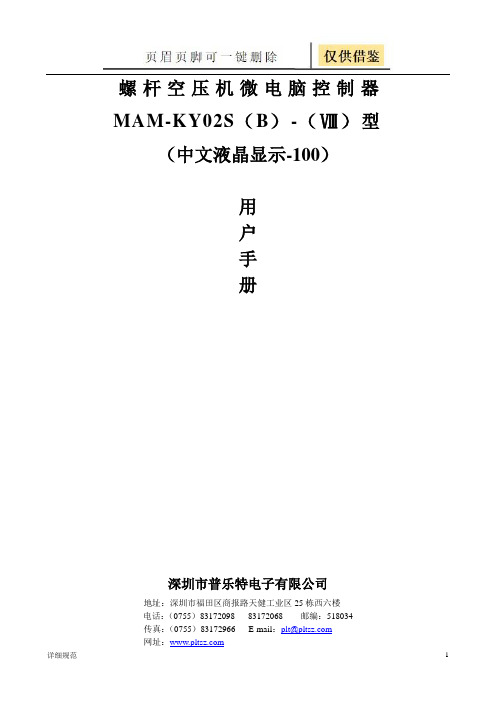
螺杆空压机微电脑控制器MAM-KY02S(B)-(Ⅷ)型(中文液晶显示-100)用户手册深圳市普乐特电子有限公司地址:深圳市福田区商报路天健工业区25栋西六楼电话:(0755)83172098 83172068 邮编:518034传真:(0755)83172966 E-mail:plt@网址:使用注意使用前,请仔细阅读使用说明书。
只有专业技术人员允许安装MAM—KY。
机械安装时务必充分考虑安装位置,确保散热良好和减少电磁干扰。
实施配线时,请按强电、弱电分开布线规则布线,减少电磁干扰。
继电器输出控制之交流接触器等感性负载必须接突波吸收器。
上电之前仔细检查输入/输出配线。
本机体之接地端子正确接地(第三种接地),可提高产品的抗杂讯能力。
电机额定电流(跳机电流)的设定按电机铭牌额定电流╳电机过载倍数/1.2倍特点:●LCD中英文显示●对电机具有短路、堵转、缺相、过载、不平衡等全方位保护功能●对电机具有起停控制、运行控制●对空压机进行防逆转保护●对多点温度进行检测与控制保护●自动调节负荷率控制压力平衡●高度集成,高可靠性,高性价比●远程/机旁选择控制●联动/独立选择运行●RS-485通讯功能一、基本操作1、按键说明排气温度:80C供压:0.60MPa运行状态:设备已停止0秒机旁ON M图1ON——起动键:按此键可起动电机运行OFF——停机键:按此键可停止电机运行M——设定键:修改完数据后,按此键确认数据存储输入❽——上移键:数据修改时,按此键上翻修改该数位;在菜单选择时作为选择键。
❾——下移键:数据修改时,按此键下翻修改该数位;在菜单选择时作为选择键。
❼——移位键/确认键:修改数据时,此键作为移位键;在菜单选择时作为确定键。
RT——返回键/复位键:在菜单操作时作为返回键返回上一级菜单;故障停机时,按此键复位。
2、状态显示与操作机组通电后显示如下界面:欢迎使用*****杆压缩机5秒后显示以下主界面:排气温度:20℃供气压力:0.60Mpa运行状态:设备已停止机旁按“❾运行参数日历a、运行参数查看按“❾”或“❽”移动黑色滚动条到“运行参数”菜单后,按确认键“❼”后弹出下一级菜单:主、风机电流运行总时间本次运行时间维护参数再按“❼”弹出电流(A):R S T主机:56.1 56.2 56.0风机: 4.1 4.1 4.1如为最后一级菜单,界面不会出现黑色滚动条,按返回键“RT”返回上级菜单或主界面。
约克YS型双螺杆冷水机组的正常运行参数R22

3.水泵的运行管理
• (1)运行检查和维护工作; • (2)运行调节
4.冷却塔的运行管理
• (1)运行检查工作; • (2)运行调节 采用的调节方式: 一是调节冷却水流量 二是调节冷却水回水温度
调节冷却水回水温度具体可采用
• 1)调节冷却塔运行台数; • 2)调节冷却塔风机运行台数;
约克YS型双螺杆冷水机组的正常运行参数(R22)
2018/10/6
运行参数 蒸发器压力 冷凝器压力 油 温
正常范围 0.450.52MPa(表压力) 0.901.40MPa(表压力) 不高于55℃
2018/10/6
•(2)运行参数调整
1)风管风量和风口风量的测定及系统风量的调整。
2)螺杆式制冷机工作参数的调整
2018/10/6
开机调试前,应先打开冷凝器的制冷剂进出口阀。开机后, 调节膨胀阀的开度,调整冷调整。 4)“露点”温度调节性能的试验与调整。 5)空调房间内气流组织的测试与调整。 6)室温调节性能的试验与调整。 7)制冷量调节性能的检验。 8)空调系统综合效果检验与测定。 2018/10/6
2)关闭贮液器或冷凝器出口的供液阀及节流阀
2.停机维护保养
2018/10/6
三、中央空调的运行调节 1.运行参数分析 (1)蒸发压力与蒸发温度 (2)冷凝压力与冷凝温度 (3)冷冻水的压力与温度 (4)冷却水的压力与温度 (5)压缩机的排气温度 (6)油压差、油温与油位高度
(7)主电机运行电流与电压
• (2)风机的启动与运转 2.水泵试运转 • (1)试运转的准备工作 • (2)水泵试运转
3.冷却塔试运转
• (1)试运转的准备工作 • (2)冷却塔试运转 4.螺杆式制冷压缩机单机无负荷试运转
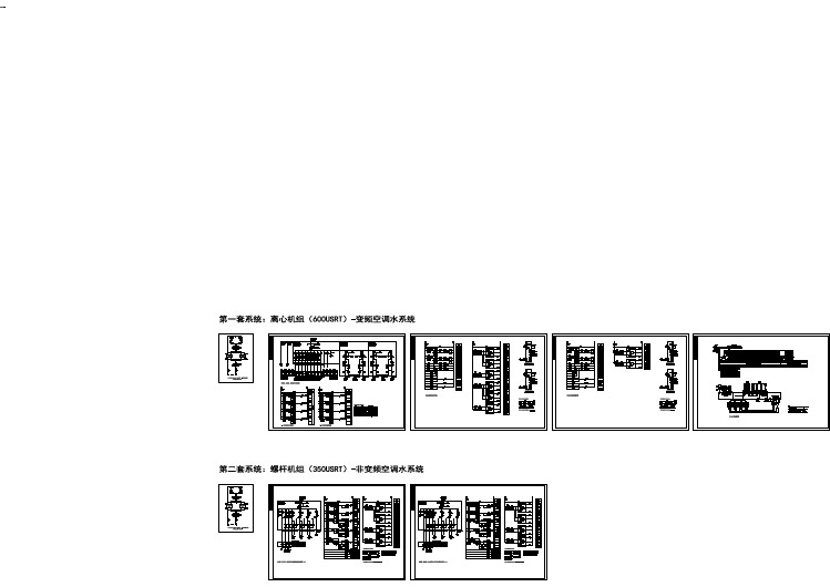
离心机组、螺杆机组中央空调水系统配电及控制原理图
- 1、下载文档前请自行甄别文档内容的完整性,平台不提供额外的编辑、内容补充、找答案等附加服务。
- 2、"仅部分预览"的文档,不可在线预览部分如存在完整性等问题,可反馈申请退款(可完整预览的文档不适用该条件!)。
- 3、如文档侵犯您的权益,请联系客服反馈,我们会尽快为您处理(人工客服工作时间:9:00-18:30)。
PRODUCT DRAWINGYORK INTERNATIONAL CORPORATIONP .O. Box 1592, YORK, PA 17405CONTRACTOR _______________________PURCHASER ____________________________________________ORDER NO.__________________________JOB NAME _______________________________________________YORK CONTRACT NO._________________LOCATION _______________________________________________YORK ORDER NO.____________________ENGINEER ______________________________________________REFERENCEDA TE ________APPROVAL DA TE ________CONSTRUCTION DATE ________Supersedes: Nothing WIRING DIAGRAMMILLENNIUM Y S (STYLE C) ROTARY SCREW CHILLERMICROCOMPUTER CONTROL CENTER WITH ELECTRO-MECHANICAL STARTERJOB DATA:CHILLER MODEL NO. YS _________________NO. OF UNITS __________________________COMPRESSOR MOTOR ________________VOLTS, 3-PHASE,______________________________H ZREMARKS:_____________________________________________________________________________________________________________________________________________________________________________________________________________________________________________________________________________________________________________________________________________________________________________________________________________________________________________________________________________________________________________________________________________FORM 160.47-PW1 (897)ELEMENTARY DIAGRAMREF. 035-09973-000, REV D(Cont d. on pages 3 & 4)LD023992 YORK INTERNATIONALFORM 160.47-PW13YORK INTERNATIONALELEMENTARY DIAGRAMLD02400LD02401TIMING DIAGRAMELEMENTARY DIAGRAM (Cont d.)4YORK INTERNATIONALFORM 160.47-PW15YORK INTERNATIONALLD02403ELEMENTARY DIAGRAM (Cont d.)NOTES:1.This wiring diagram describes the standard electroniccontrol scheme for use with an Electro-Mechanical Starter. For details of standard modifications (by oth-ers), refer to Product Drawing Form 160.47-PW5.2.Field wiring to be in accordance with the NationalElectrical Code as well as all other applicable codes and specifications. See Product Drawing Form 160.47-PW3 for field wiring connections.3.Numbers along the left side of diagram are line iden-tification numbers. The numbers along the right side indicate the line number location of relay contacts.An underlined contact location signifies a normally closed contact.4.Main control panel Class 1 field wiring terminal con-nection points are indicated by numbers within a rect-angle, i.e. 15 . Main control panel factory wiring terminal connection points are indicated by numbers within a triangle, i.e. 5 . Component terminal markings are indicated by numbers within a circle, i.e.C1 . Numbers adjacent to circuit lines are the circuit identification numbers.5.To cycle on and off automatically with contacts otherthan those shown, install a cycling device between terminals 1 & 13 (line 27) (see Note 9). If a cycling device is installed, jumper must be removed between terminals 1 & 13 .pressor motor starter with starter interlock con-tacts (rated 0.2 amps @ 120 volts A.C.) must be per Form 160.47-PW7. Control panel shall be grounded.7.Units installed in Canada must have a field suppliedCSA approved 30 amp disconnect switch and a 15 amp dual element fuse mounted external to control panel for 115 volt control supply.8.To stop unit and not permit it to start again, install astop device between terminals 1 & 8 (line 23) (see Note 9). A Remote start-stop switch may beconnected to terminals 1 , 7 & 8 (lines 22 and23) (see Note 9). Remote start-stop switch (line 22)is operative only in the remote operating mode.9.Device contact rating to be 5 miliamperes at 115 voltsA.C.10.Contact rating is 5A resistive @ 120 volts A.C. or240 volts A.C.11.To check motor rotation on initial start-up, install mo-mentary switch between terminals 24 & 25 (line35). Depress start switch, after approx. 30 seconds,jog motor with momentary switch. When proper rota-tion is obtained, replace momentary switch with jumper. Switch must have a minimum contact rating of 2 FLA, 10 LRA at 115 volts A.C.12.Solid state motor overload (CM) is set to trip at 105%FLA. During momentary power interruption (power fault), contact also opens for 1 second.13.For high and low voltage units, the factory suppliedjumper between 1 & 53 must be removed when Electro-Mechanical starter overloads and/or safety devices are used. For high voltage (2300-4160) UL and CSA approved units only, electro-mechanical compressor motor starter overloads (normally closed) must be connected between 1 & 53 .14.Contact rating is 5 amps resistive @ 250 volts A.C.& 30 volts D.C., 2 amp inductive (0.4 PF) @ 250 volts A.C. & 30 volts D.C.15.Each 115VAC field-connected inductive load, i.e. re-lay coil, motor starter coil, etc. shall have a transient suppressor wired in parallel with its coil, physically located at the coil. Spare transient suppressors and control circuit fuses are supplied in a bag attached to the top of the hinged panel.16.Low oil pressure (LOP) safety shutdown occurs whenoil pressure evaporator pressure differential is less that 15 psi following a 3 minute bypass at compres-sor start.LEGENDLD024026 YORK INTERNATIONALFORM 160.47-PW17YORK INTERNATIONALPRESSURE TEMPERATURE CHARTLD02404* Function provided by condenser transducerCONNECTION DIAGRAM8YORK INTERNATIONALFORM 160.47-PW19YORK INTERNATIONALCONNECTION DIAGRAMLD02405CONNECTION DIAGRAM (Cont d)10YORK INTERNATIONALFORM 160.47-PW111YORK INTERNATIONAL LD02406CONNECTION DIAGRAM (Cont d)P.O.Box1592,YORK,Pennsylvania USA17405-1592Subject to change without notice.Printed in USA Copyright©by YORK International Corporation1997ALL RIGHTS RESERVED Form160.47-PW1(897)Supersedes:Nothing。