AC伺服驱动Σ-V系列综合样本
电动驱动器 - 长杆型 - AC Servo 电机规格 LX-135A-AB说明书

Electric Actuator- Long Stroke Type- AC Servo Motor SpecificationsLX-135A-ABFeature 1: Maximum speed 1000mm/s. (for Ø10, 20mm lead.)- Ball screw: Ø10, 10, 15, 20mm lead →Ø8, 2mm, 5mm lead for standard model.Feature 2: Long stroke specifications (Maximum 400mm)→Maximum 200mm stroke for LXP standard modelFeature 3: Panasonic AC servo motor (50W)(Matsushita Electric Industrial Co., Ltd.) (See note1)- Types of motors (Model No.: MSM5AZP1A, MSM5AZP1B)- Types of driver units (Model No.: MSD5A1P1E, MSD5A3P1E)SpecificationsElectric actuatorModel LX-135A-ABELX-135A-ABFLX-135A-ABG Stroke mm 50, 100, 150, 200, 250, 300, 350, 400Motor specifications 【Model No.】Panasonic AC servo motor (50W) 【Model No.】MSM5AZP1A(Without brake)MSM5AZP1B (With brake)Driver unit 【Model No.】Panasonic driver unit for AC servo motor 【Model No.】MSD5A1P1E (For 100VAC) MSD5A3P1E (For 200VAC)Screw (Ball screw) Ø10; Lead: 10mm Ø10; Lead: 15mm Ø10; Lead: 20mmHorizontal 6kg Maximumpayload Vertical 5kg 4kg 3kg Maximum thrust 149.7N 99.8N 74.9NMaximum speed (Note 2) 500mm/s 750mm/s 1000mm/sPositioning repeatability ±0.03mmType of guide Linear ball bearingOperating temperature range 5 to 40℃(With no condensation)Home position auto switch PM-L24 (Manufacturer: SUNX Corporation) (See note 1)Proximity microswitch(Manufacturer: SUNX Corporation) (See note 1)- Microswitch model No. - Microswitch specificationsSymbol Model No. Type of switch Model No. GXL-8F(B) GXL-8FU GXL-8FUBGU GXL-8FU N.O. type; 2 wires Repeatability Front sensing, Top sensing: 0.04mm or lessGUB GXL-8FUB N.C. type; 2 wires Power supply voltage 12 to 24VDC±10%, Ripple p-p10% or lessG GXL-8F N.O. type; 3 wires Current consumption 15mA or less0.8mA or less (With output OFF)GB GXL-8FB N.C. type; 3 wiresControlled outputNPN TransistorMax. load current: 100mAMax. applied voltage : 30VDCResidual voltage: 1V or lessNon-contactDC 2-wire typeLoad current: 3 to 70mAResidual voltage: 3V or lessMaximumresponsefrequency500Hz 1kHzIndicator lightRed LED(Lights up when output is ON)Green LED (Stable sensing condition)Red LED (Unstable sensing condition)Note 1) Refer to each manufacturer’stechnical information for furtherdetails.Note 2) Due to the acceleration setting that is chosen, as well as payloadconditions, it is possible that themaximum speed will not beachieved in certain applications. Operating temperaturerange -10 to 55℃-25 to 70℃SP017X-009EIssued: Aug 2001SMC CORPORATION1-16-4 Shimbashi, Minato-kuTokyo 105-0004, JAPANURL: P.G. InformationSupplement: If a Panasonic motor driver unit is selected, a power supply connector (5557-10R by Molex) and an interface connector(10126-3000VE by Sumitomo/3-M Limited) are also required.Note 2: If motor/driver unit voltage 100VAC or 200VAC is selected from the How to Order page,a driver unit will automatically be shipped together with your order.Note 3: The lead wire is connected to EE-SX673 at the factory prior to shipment.。
AC伺服驱动器
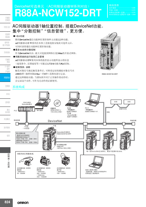
3G8F7-DRM21
Tߚᬃ ˄1ߚᬃൟ˅
᳔㔥㒰䭓ᑺ ˄Փ⫼THICK⬉㓚ᯊ˅
䗮ֵ䗳ᑺ500kbpsϟ 100m˄ᑆ㒓İ6mǃᬃ㒓İ39m˅ 䗮ֵ䗳ᑺ125kpbsϟ 50 0 m˄ᑆ㒓İ6mǃᬃ㒓İ156m˅
U V W B2 B1 L2C L1C
- + 2 + 1 L2 L1
ACԎ᳡⬉ᴎ W㋏߫ ᠕ᑇൟ ˄3000r/min˅ 100̚1500W
PC व ˄ᏺ䜡㕂䕃ӊ˅
3G8E2-DRM21-V1
Ңキ
Ңキ
ᬃ㒓
ᬃ㒓ৃߚᬃ
㒜ッ⬉䰏
- + 2 + 1 L2 L1
AC SERVO DRR8IV8EDR-WTA5H 200V
50W
MODE/SET CHARGE
L1
DATA/ POWER
电机1转分割为指定的等分后定位(1~32,767等分)
在指定位置减速停止(正负均可在±99,999,999范围内设定方向)
远程I/O通信、可根据输入信号
可根据远程I/O通信
跟踪对象模拟量数据 (可选择2要素)
指令脉冲速度[r/min]、位置偏差[指令单位]、速度反馈[r/min]、 转矩指令[%]
跟踪对象ON/OFF数据 (可选择2要素)
设定AC伺服电机是作为直线轴使用,还是作为旋转轴使用
定位中的速度,最多可进行16段变速(多段速定位运行时)
无极限反转
原点附近信号+原点信号、原点信号、原点附近信号+Z相、Z相、其中之一使用ON/OFF信号
有极限反转
原点附近信号+原点信号、原点信号、原点附近信号+Z相、其中之一使用ON/OFF信号
安川伺服中文样本
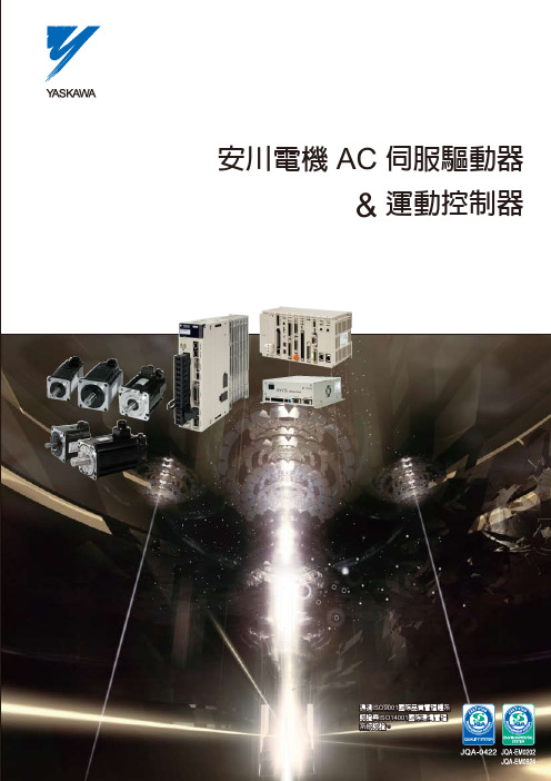
超群與靈活的機電整合系統 安川電機 AC伺服驅動系統
即時核心通信網路
Cell/Line 控制
程式編輯軟體 MPE720
P21
運動控制
運動控制器 MP2000 系列
P22-23
高速專用 通信網路
MPE720 MP2100
驅動器
AC 伺服驅動器 P6-13
伺服驅動器 P14-15
SGDV
MPLOGGER MEMOLOGGER
位置指令速度 定位完成
位置指令速度 定位完成
具備因摩擦使響應改變的補償機能,使伺服響應性更加安定。
無摩擦補償 約0~30%摩擦所產 生之位置偏差變動 位置偏差pulse
定位完成 約20ms變動
使用摩擦補償 約0~30%摩擦所產 生之位置偏差變動 位置偏差pulse 定位完成
約1ms變動
搭配中慣量伺服馬達d讓設備性能向上提升
*SGMAV-02ADA, SGDV-1R6A 負載慣量比值為1倍時
速度響應頻率特性
轉矩指令 速度指令
位置
速度 速度 轉矩
指令
位置 控制部 指令
控制部
指令
電流 控制部
馬達定時間
位置指令 速度
位置偏差
定位完成
整定時間0~4ms!
將振動與摩擦影響的抑制機能強化
運轉
簡單調整
解決往常製品的Auto-Tuning問題點
馬達組裝後欲立即動作
新調整LESS機能(出廠設定)
即便沒有伺服調整,在容許負載慣量內,負載產生變動的情況下,伺服馬達也 不會發生振動,仍可正常動作。
1 不限指令、摩擦大小、機構分類,可常時安定運轉。此外即便在搬送過程中 ,負載有大的變化,機構仍可保持安定狀態。
安川伺服电机V中文说明书1-7
· Σ-V系列絕對值檢測系統的多回轉資料的輸出範圍與原系統(15位元編碼器、12位元編碼器)不同。特 別是 Σ 系列的“無限長定位系統”由 Σ-V 系列構成時,請務必變更系統。
· 安裝在機械上開始運轉時,請事先將馬達置於可隨時緊急停止的狀態。 否則會導致人員受傷、機械損壞。
· 請絕對不要觸摸伺服驅動器內部。 否則會導致觸電。
· 在通電狀態下,請務必安裝好電源端子台的外蓋。 否則會導致觸電。
· 在關閉電源後的5分鐘內,請勿觸摸端子。 否則會因殘留電壓而導致觸電。
· 在耐電壓試驗後的5分鐘內,請勿觸摸端子。 否則會因殘留電壓而導致觸電。
Σ-V 系列的SGMAV、SGMJV、SGMGV、SGMPS、SGMCS(直接驅動)型伺服馬達
SERVOPACK (伺服驅動器) Σ-V 系列的 SGDV 型伺服驅動器
伺服單元
伺服馬達與伺服驅動器的配套
伺服系統
由伺服驅動器和上位控制器以及週邊裝置配套而成的一套完整的伺服控制系統
類比·脈波型
伺服驅動器的介面規格為類比電壓·脈波指令型
AC 伺服驅動器 Σ-V 系列型錄 (資料編號∶ KACPS80000042)
Σ-V 系列 SGM V/SGDV 使用手冊 數位操作器 操作篇 (資料編號∶ SIJPS80000055)
Σ-V 系列 AC 伺服單元 SGDV 安全注意事項 (資料編號∶ TOBPC71080010)
Σ 系列 數位操作器 安全注意事項 (資料編號∶ TOBPC73080000)
請事先務必閱讀
本手冊是對 Σ-V 系列伺服驅動器的設計、維護所需的資訊進行說明的手冊。
Σ-7与Σ-V参数比较

8
噪音 滤波 器
Pn416 ~ Pn41F
有
无
A型阻 尼控 Pn166 制功 能 免调 整值 设定 报警 追踪 Pn170.2
有
无
设定范围:0~7
设定范围:0~4
Pn548
0000
无
Σ-7& Σ-V伺服参数比较 (M&CO1509-04 -10/11)
类别 序号 Pn55A Pn824 消费 电力 显示 Pn825 Un032 ~ Un034 Pn824 设置 环境 监测 Pn825 Un025 Un026 说明 功耗监视单位时 间 选购件监控 1 选 择 选购件监控 2选 择 功耗[W] 功耗[0.001Wh] 累积功耗[Wh] 选购件监控 1 选 择 选购件监控 2选 择 设置环境监视 - 伺服单元 设置环境监视 - 伺服电机 Σ-7
Pn30A Pn406
伺服OFF 及强 制停止时的减 速时间 紧急停止转矩
出厂设定:0
无
出厂设定:800 0: 1: . . . . . . . . F: 出厂设定:10000
出厂设定:800
Pn516.0
强制停止输入 (FSTP)信号 的分配
无
最高 速度 设定
Pn316
电机最高速度
无
Σ-7& Σ-V伺服参数比较 (M&CO1509-04 -7/11)
(M&CO1509-04 -1/11)
Σ-7与Σ-V参数比较
资料编号:(M&CO1509-04)
YASKAWA ELECTRIC (CHINA)CO.,LTD M&CO1509-04
Σ-7& Σ-V伺服参数比较 (M&CO1509-04 -2/11)
Σ-V-MD系列 AC伺服单元安全注意事项说明书

Σ-V -MD 系列AC 伺服单元安全注意事项型号:SGDV-MDA02E8M3AΣ-V -MD Series AC SERVOPACK SAFETY PRECAUTIONS MANUAL NO. YASTKSV-20027A为了您对产品的安全使用,请务必阅读本手册。
同时,请妥善保管本手册,并保证将其交给最终用户手中。
T ype: SGDV-MDA02E8M3ATo properly use the product, read this manual thoroughly and retain for easy reference, inspection, and maintenance. Ensure the enduser receives this manual.A02型T ype A02Copyright © 2020 安川电机(中国)有限公司未经本公司的书面许可,严禁转载或复制本书的部分或全部内容。
C-1与安全有关的标记说明本资料中有关安全的内容,使用如下标记进行说明。
有关安全标记的说明,表示重要内容,请务必遵守。
一般注意事项• 为了说明产品的细节部分,本资料中的插图在描绘时去掉了外罩或安全保护体。
在实际运行时,请务必按规定将外罩或安全保护体安装到原来的位置,再根据用户手册的说明进行运行。
• 本资料中的插图为代表性图例,可能会与您收到的产品有所不同。
• 由于产品改良、规格变更以及为提高本资料的使用便利性,我们将会适时对本资料进行变更。
变更后,本资料的资料编号将进行更新,并作为改订版发行。
• 对于客户自行改造的产品,本公司不对质量提供任何保证。
对于因改造产品所造成的伤害及损失,本公司概不负责。
表示错误使用时,将会引发危险情况,导致人身伤亡。
表示错误使用时,将会引发危险情况,导致轻度或中度人表示禁止(绝对不能做)。
例如严禁烟火时,则表示为。
表示强制(必须做)安全注意事项C-2C-3保管、搬运C-4安装C-5接线C-6C-7运行C-8维护·检查废弃关于保修保证期限产品的保证期限以向贵公司或贵公司客户交货后一年以内,或出厂后18个月以内两者中先至时间为准。
4.安川Σ-V伺服驱动_SigmaWin调试实习3

反共振:负载轴在动,但电机轴却保持不动的频率就是反共振频率。 注:这里①和②实际是重合的,为了便于理解,描画了两条线。
安川电机(中国)有限公司
21
4.2.4 实践准备
1)设置实时监测1:速度控制模式时
实时监测窗口
③从下拉列表选中“Speed referenece”,然后单击 “Apply”。 ④设定采样时间为“1000” (可采样1000μs x 1000 = 1 s 的数据。)
运动控制培训课程
20
4.2.3 机械分析
2.惯性负载引起的共振和反共振
电机(转子的惯量)和负载(的惯量)通 过弹簧连接的机构称为2惯性模型。
电机(转子的惯量)和负载(的惯量)直 连的机构称为刚性模型。
在2惯性模型中,电机轴会出现反共振现象。
振幅(dB)
①
负载轴
共振 共振频率
反共振频率 电机轴
②
频率(Hz) (对数刻度) 反共振
单参数调谐安川电机中国有限公司5413伺服调整功能的调整对象免调整位置速度增益惯性转矩比摩擦补偿自动陷波滤波器aa型抑振控制振动控制转矩指令滤波器模型追踪控制aat指令输入aat单参数调谐免调整检测出振动时使用安川电机中国有限公司6414模型追踪控制和摩擦补偿模型追踪控制
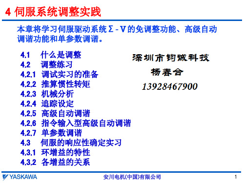
4 伺服系统调整实践
本章将学习伺服驱动系统Σ‐Ⅴ的免调整功能、高级自动 调谐功能和单参数调谐。 4.1 4.2 4.2.1 4.2.2 4.2.3 4.2.4 4.2.5 4.2.6 4.2.7 4.3 4.3.1 4.3.2 什么是调整 调整练习 调试实习的准备 推算惯性转矩 机械分析 追踪设定 高级自动调谐 指令输入型高级自动调谐 单参数调谐 伺服的响应性确定实习 环增益的特性 各增益的关系
SMC AC伺服电机驱动器LECSA系列说明书

Do not drop, hit or apply excessive shock to the product. Prevent any foreign matter from entering the product. Use the product within the specified ambient temperature range. If abnormal heating, smoke or a fire occurs in the product, immediately
IEC 60204-1: Safety of machinery - Electrical equipment of machines. (Part 1: General requirements) ISO 10218-1: Robots and robotic devices - Safety requirements for industrial robots - Part 1: Robots. Refer to product catalogue, Operation Manual and Handling Precautions for SMC Products for additional information. Keep this manual in a safe place for future reference.
A regenerative resistor is mounted on the back of the LECSA. The regenerative resistor causes a temperature rise of 100°C relative to the ambient temperature. Fully examine heat dissipation and the installation position before installing the driver.
伺服电机及驱动综合样本-1406

DDS
数字伺服驱动系统
发格数字伺服驱动系统为需要平滑、快速、精确加工的机床制造者提供 完美的解决方案。
常 规特性
接口 速度反馈 保护 控制 直接位置反馈 精插补 Sercos 或模拟量 高分辨率正弦波编码器 过压, 过流, 超速, 超温, 过载等. 高速主轴和嵌入式电机 差动 TTL, Vpp, 带距离编码器的参考标志, Fagor绝对值 位置环(250微秒)和速度环(62.5微秒)
RPS 系 列
带能量调节的课再生电源,提供了一个可编程的DC输出电压(不管电源电压),剩余的的能量返回到主电源,可降低系统的功耗,且 不会产生额外的热量.
RPS-20 输入电压 输出电压 额定 (峰值) 输出功率 额定 (峰值) 输出电流 提供给驱动器的控制信号电压 关联电抗器 宽 20 kW (26 kW in S6) 32 A (41.6 A in S6) 24 V DC (192 W) Choke RPS-20 194 mm
XPS-25
XPS-65
三相 50/60 Hz, 360 V AC 到 506 V AC 565 - 650 V DC 25 kW (75 kW, 1s) 45 A (135 A, 1s) 24 V DC (240 W) 16.5 � (500 W) 77 mm 565 - 650 V DC 65 kW (195 kW, 1s) 120 A (360 A, 1s) — 9 � (600 W) 117 mm
发格电源模块连接到三相交流电源(360 to 506 VAC,50/60 Hz ),通过动力总线向驱动模块 的提供电源。他们还负责管理制动电机时产生的 能量。
PS 系列
非再生电源. 制动时产生的能量以热能方式释放 .
∑-Ⅴ系列样本

ᣀᅽ /eN
4(.+7"
ᣀ
ᤳ
NJO
"
#
ᣀᅽ /eN
4(.+7"
ᣀ
ᤳ
NJO
"
#
ᣀᅽ /eN
7
伺服电机
SGMJV 型
旋转型
外形尺寸 mm
( 注 ) 型号的第 7 位是“S”或“E”。 键尺寸同上表。
8
外形尺寸 mm
(2) 200 ~ 750W .%Fra bibliotek-
--
-.
-(
"
-3 -&
φ "
ƾ-$ .8
φ 4I φ -#I
.) 8
2, 6
:
:
"
φ -"
ᛂጮfຆऎ
φ-;
5 ᭦::
#
ᣀᅽ /eN
4(.+7"
ᣀ
ᤳ
NJO
"
#
ᣀᅽ /eN
4(.+7"
ᣀ
ᤳ
NJO
"
#
ࣛ᪃֖ᛂጮ ᣈቪសڎ
型号 SGMJV-
L
法兰面尺寸
键尺寸
LL
LM
S 螺纹 × 深度
LR LE LG LC LA LB LZ
AC伺服主轴+MDS-C1系列-主轴参数一览表

说明
《对于 MDS-C1-SP/SPH》
F E D C B A 9 8 7 6 54 3 2 1 0
poff hzs
ront
pycal pychg pyst pyoff
sftk dflt 1a2m
bit
设定为 0 时的意义
1a2 1 放大器 2 电机功能:无效 0m
1 dflt 默认电机:主
2 sftk 无 SF-TK 卡
设定为 1 时的意义
标准
0
0
0
0
0
0
0
0
0
最小励磁率的高速区域降低方式有
效
0
0
0
READY ON 高速
0
MDS-B-PJEX 连接有效
1
通过高周期零速度实现门关闭有效 0 NC 电源关闭时接触器保持有效 0
在简称上加有“*” 符号(如 osp* 等)的参数、是在 NC 电源重启后才有效的参数。
3-59
1~32767
设定相对于齿轮 001 的主轴侧齿数。
1~32767
设定相对于齿轮 010 的主轴侧齿数。
1~32767
设定相对于齿轮 011 的主轴侧齿数。
1~32767
设定相对于齿轮 000 的电机轴侧齿数。
1~32767
设定相对于齿轮 001 的电机轴侧齿数。
1~32767
设定相对于齿轮 010 的电机轴侧齿数。
速度控制时· SP022 VGNP1* 速度环比例增益
速度控制时· SP023 VGMI1* 速度环积分增益 SP024 SP025 GRA1* 主轴侧齿轮齿数 1 SP026 GRA2* 主轴侧齿轮齿数 2 SP027 GRA3* 主轴侧齿轮齿数 3 SP028 GRA4* 主轴侧齿轮齿数 4 SP029 GRB1* 电机轴端齿轮齿数 1 SP030 GRB2* 电机轴侧齿轮齿数 2 SP031 GRB3* 电机轴侧齿轮齿数 3 SP032 GRB4* 电机轴侧齿轮齿数 4
COPLEY综合样本

伺服驱动器步进驱动器控制软件Copley Controls 为广泛的工业应用提供高性能的运动控制解决方案。
应用包括半导体,生命科学,自动化装备,测试和测量,以及COTS 军工。
作为一个 ISO 9001:2008 企业, Copley 生产符合 RoHS 认证的高质量产品。
Copley 为所有的驱动器产品提供 2 年质保期。
Copley 在与OEM 客户合作方面已有超过 25 年的经验。
Copley 拥有高素质,快响应的研发以及应用支持团队。
我们的销售及技术支持团队遍布美国,欧洲和亚洲,旨在提供全球化的服务。
关于Copley作为Analogic 集团公司的一部分,Copley C ontrols 拥有强大的资源以及购买力以应对全球市场的竞争。
我们的产品经受了时间的考验,许多型号产品的生产已超过10年。
从可实现网络连接控制的伺服和步进驱动器到传统的力矩控制驱动器,Copley 可根据客户的应用需求提供专业的解决方案。
Copley 可提供功率在 100W - 6kW 范围内安装结构灵活的驱动器。
并提供交流和直流两种供电方式以便选择。
Copley 驱动器提供了全面的电机反馈接口。
先进的调节和整定算法极大地提高了电机的使用性能。
一些型号的伺服驱动器可提供恶劣环境版本,适用于COTS 军工应用。
由于驱动器设计的耐温范围更宽,防潮,抗震动及抗冲击性能更强,Copley R 系列驱动器在恶劣环境中可提供高可靠性能。
伺服 & 步进 驱动器Copley 驱动器参数配置软件界面清晰直观,并带有功能强大的诊断工具。
软件集成了简单易用的 Indexer 编程工具。
Copley 还提供了灵活性更高的高级编程语言以适应更加复杂的应用。
网络软件工具使得多轴控制系统的开发快速而便捷。
可靠的源码软件可支持 EtherCAT 和 CANopen 两种网络应用程序的管理和执行。
并且应用程序可实现从 CANopen 到 EtherCAT 的直接无缝移植。
富士AC伺服系统FALDIC-W系列用户手册 参数

希望帮到您!5 参数5 - 1参数构成5 - 2参数一览表5 - 3参数的说明希望帮到您!顺序模式监控器模式 参数编集模式 试运行模式 参数构成伺服放大器中有调整机械系统的设定、伺服的特性与精度的各种参数。
由于参数的设定值被存储在可电换写的ROM(EEPROM)中,因此,即使切断电源也不会丢失。
作为参数一览表的“变更”项目的“电源”的参数,即使切断主电源,再接通电源时仍然有效。
(请确认主电源切断时,伺服放大器的触摸面板<7段文字显示>灯灭。
)■参数的编集方法有两种编集方法,即触摸面板编集法和电脑编程器编集法。
5.1.1 利用触摸面板编集的方法利用键选择参数编集模式,利用/键选择参数编号。
选择模式接通电源选择子模式显示例希望帮到您!5.1.2 利用电脑编程器编集的方法利用电脑编程器设定。
希望帮到您!参数一览表■参数速查表(1)希望帮到您!■参数速查表(2)希望帮到您!希望帮到您!※()内为GYG型电机的初始值。
※()内为GYG型电机的初始值。
※1) 指刚执行完“参数初始化”后的值,在05调整模式中若选择了“自动调整”或“半自动调整”希望帮到您!,将自动更新。
希望帮到您!希望帮到您!<α/β设定画面>5.2参数说明按编号顺序记载参数的设定内容。
/-参数01~02号 编号 名称设定范围 初始值 变更 01 命令脉冲补偿α 1~32767(1刻度) 16 一直 02命令脉冲补偿β1~32767(1刻度)1一直※只在位置控制时有效。
以每一命令脉冲的机械系统的移动量为单位量设定参数(电子齿轮)。
利用以下计算式计算。
■命令脉冲补偿α/β计算式请约分,使命令脉冲补偿α/β变为整数(32767以下)。
■利用电脑编程器设定可以利用电脑编程器的参数编集画面“利用机械构成设定α/β”,自动设定命令脉冲补偿α/β。
只输入机械规格就可自动设定。
另外,由于划分为不同的机械构成,故可以简单输入。
(伺服电机旋转1周时的机械系统移动量)131072脉冲/转命令脉冲补偿α 命令脉冲补偿β命令脉冲补偿α 命令脉冲补偿β131072脉冲/转(伺服电机旋转1周时的机械系统移动量)※ 单位量为「1」,「0.1」,「0.01」,「0.001」等数值。
安川伺服选型样本

安川伺服选型样本1.介绍安川电机安川电机是一家全球领先的工业自动化和机器人技术供应商,成立于1915年,总部位于日本。
公司致力于为世界各地的制造业提供高质量、高性能的产品和解决方案。
安川电机的产品线涵盖伺服驱动器、控制器、机器人、PLC、触摸屏等。
2.样本选型条件在进行安川伺服选型时,需要考虑以下几个条件:-应用需求:根据具体的应用需求,包括负载类型、负载惯性、加速度、速度和位置精度等。
-功率要求:伺服系统的功率需求是选型的重要考虑因素。
-电源和电压:选择合适的电源和电压,以满足实际应用的要求。
-控制方式:根据应用的控制要求,选择合适的控制方式,包括位置控制、速度控制和力控制等。
-机械接口:机械接口的选型要与实际应用相匹配,确保伺服系统与其他设备的连接稳定可靠。
3.样本选型及应用示例样本1: Sigma-7系列伺服驱动器- 产品特点: Sigma-7系列伺服驱动器采用了领先的1000Hz采样率和20-bit分辨率的编码器技术,提供了卓越的性能和精度。
同时具备快速的加速度响应、快速的寻位精度和平缓的运动特性。
-应用示例:适用于需要高速、高精度和高刚性的应用,如半导体设备、自动化工作站、机床等。
样本2:SGMMV系列直驱伺服电机-产品特点:SGMMV系列伺服电机采用了无刷有刷开关技术,具有高效、高响应、高刚性等特点。
同时,电机结构紧凑,重量轻、噪音小、寿命长。
-应用示例:适用于需要高速、高精度和高刚性的应用,如半导体设备、机床、印刷设备等。
样本3:WVZA系列伺服驱动器-产品特点:WVZA系列伺服驱动器采用先进的矢量控制技术,具有高速响应、高稳定性和精确的位置和速度控制能力。
同时,该系列驱动器具有紧凑设计、高效节能等特点。
-应用示例:适用于需要高性能和低噪音的应用,如包装机械、纺织机械等。
样本4:SGD7S系列高压伺服驱动器-产品特点:SGD7S系列伺服驱动器采用了电流控制技术,具有卓越的性能和稳定性。
安川伺服驱动器使用说明书.

资料编号SICP S800000 45C用户手册设计²维护篇模拟量电压²脉冲序列指令型/旋转型©-V系列伺服单元SGDV伺服电机SGMJV/SGMAV/SGMPS/SGMGV/SGMSV/SGMCSAC伺服驱动器概要面板操作器接线和连接试运行运行调整辅助功能(Fn□□□监视显示(Un□□□全闭环控制故障诊断附录版权所有© 2007 株式会社安川电机未经本公司的书面许可,禁止转载或复制本书的部分或全部内容。
iii请事先务必阅读本手册是对©-V 系列伺服单元的设计、维护所需的信息进行说明的手册。
进行设计、维护时,请务必参照本手册,正确进行作业。
请妥善保管本手册,以便在需要时可以随时查阅。
除本手册外,请根据使用目的阅读下页所示的相关资料。
本手册使用的基本术语如无特别说明,本手册使用以下术语。
关于重要说明对于需要特别注意的说明,标示了以下符号。
本手册的书写规则在本手册中,反信号名(L 电平时有效的信号通过在信号名前加(/来表示。
<例>S-ON 书写为/S-ON。
基本术语意义伺服电机©-V 系列的SGMJV、SGMAV、SGMPS、SGMGV、SGMSV、SGMCS (直接驱动型伺服电机伺服单元©-V 系列的SGDV 型伺服放大器伺服驱动器伺服电机与伺服放大器的配套伺服系统由伺服驱动器和上位装置以及外围装置配套而成的一套完整的伺服控制系统模拟量²脉冲型伺服单元的接口规格为模拟量电压²脉冲序列指令型M-ⅠⅠ型伺服单元的接口规格为MECHATROLINK-II 通信指令型²表示说明中特别重要的事项。
也表示可能会引起警报等,但还不至于造成装置损坏的轻度注意事项。
iv©-V 系列的相关资料请根据使用目的,阅读所需的资料。
资料名称机型和外围设备的选型想了解额定值与特性进行系统设计进行柜内安装与接线进行试运行进行试运行²伺服调整进行维护和检查©-V 系列用户手册设定篇旋转型(资料编号∶ SICPS80000043AC 伺服驱动器©-V 系列综合样本(资料编号∶ KACPS80000042©-V 系列用户手册数字操作器操作篇(日文版(资料编号∶ SIJPS80000055©-V 系列AC 伺服单元SGDV安全注意事项(资料编号∶ TOBPC71080010© 系列数字操作器安全注意事项(资料编号∶ TOBPC73080000AC 伺服电机安全注意事项(资料编号∶ TOBPC23020000v与安全有关的标记说明本手册根据与安全有关的内容,使用了下列标记。
安川伺服 Σ-Ⅴ自调谐
∑-V自动调谐的注意事项<概要>本文介绍的是∑-V自动调谐的注意事项和SigmaWin功能的应用示例。
本文将围绕下面3个项目进行详细阐述。
今后我们将继续探讨并实施SigmaWin的功能以及说明书中的明确记载。
①欲通过内部指令型高级自动调谐变更指令形态(移动速度等)时的处理方法⇒替代SigmaWin的“程序JOG运行”。
②高级自动调谐(AAT)不能正常完成或不能抑制振动时的处理方法⇒与高分辨率的编码器无关,定位完成宽度太小时,设定适宜的定位完成宽度(Pn522)。
或暂时增大到Pn522,待AAT适用后,再将Pn522恢复为原设定,然后通过单参数调谐进行微调。
⇒不能检测出或不能抑制振动时,通过机械分析、运行时的跟踪来判断频率,然后手动设定陷波滤波器、A 型减振、振动抑制。
③对不稳定的阶梯状指令响应跟踪过头时的处理方法(Σ-V 有时会发生AAT 时增益上升过高,对不稳定的指令跟踪过头而产生振动和噪音的情况。
)⇒手动设定指令类滤波器(移动平均滤波器等)。
欲通过内部指令型高级自动调谐变更指令形态(移动速度等)时的处理方法下面介绍一下程序JOG运行时高级自动调谐的步骤。
图1 高级自动调谐的条件设定对话框程序JOG运行(SGDV、SigmaWin+)时高级自动调谐的步骤下面介绍一下程序JOG运行时高级自动调谐(AAT)的方法。
程序JOG运行的指令作为模拟的外部指令,实施外部指令输入型AAT。
程序JOG运行无需连接上游装置即可任意控制伺服电机的功能。
可设定移动距离、移动速度、加减速时间、运行次数等,还可简单地变更运行条件。
详细内容请参考用户手册。
下面介绍操作步骤。
①从SigmaWin菜单中选择[测试运行]⇒ [程序JOG运行]。
(图2)②在程序JOG运行的设定对话框内设定移动距离、移动速度、加减速时间、运行次数等。
(图2)③执行程序JOG运行,使伺服连续运行。
(图2)④从SigmaWin菜单中选择[自动调谐]。
安川Σ-V伺服驱动_SigmaWin调试实习
①因为事先已推算过转动惯量比,所以这里选 择“1:A moment of inertia is not presumed”。
②模式选择设为“2:Positioning”。 ③机构选择设为“2:Ball screw mechanism
or linear motor” 。 ④由于设定了指令单位0.001(mm)的电子齿轮
安川电机(中国)有限公司
1
4.1 什么是调整
调整(调谐)是优化伺服单元响应性的功能。响应性取决于伺 服单元中设定的伺服增益。
一般情况下,刚性高的机械可通过提高伺服增益来提高响应性。 但对于刚性低的机械,当提高伺服增益时,可能引起振动,从 而无法提高响应性。
伺服增益通过多个参数的组合进行设定,彼此之间相互影响。 本章我们将实践练习如何设定各参数,并保持设定值之间的平 衡。
※滚珠丝杠移动轴的例子
整定时间: 241.33ms
整定时间:241.33ms
Pn100 Kv Pn101 Ti Pn102 Kp Pn401 Tf
: 40.0Hz : 20.00ms : 40.0/s : 1.00ms
安川电机(中国)有限公司
24
4.2.5 高级自动调谐
高级自动调谐是伺服单元根据内部指令自动运 行时,对以下机械特性自动进行调整的功能。
⑤再次点击菜单项 “Tuning”。
⑥ 单击窗口②的 “Execute”按钮,将 显示测算惯性转矩的 窗口。
④单击“OK”,并 重启电源。
11
4.2.2推算转动惯量
2)设定惯性转矩比的步骤1 执行测算惯性转矩的功能,系统可快速计算出作用在电机轴的负载惯性转矩。
①单击“Execute” 。
②显示条件设定窗口(本次 练习不修改窗口中数值), 单击“Next” 。
高性能标准AC驱动器(0.75~75kW 1~100HP至0.75~375kW 1~500HP)三相

iS7 High Performance Standard AC Drive0.75~75kW(1~100HP) 3-Phase 200~230Volts0.75~375kW(1~500HP) 3-Phase 380~480VoltsIP54 0.75kW~22kW(1~30HP) 3-Phase 200~230VoltsIP54 0.75kW~22kW(1~30HP) 3-Phase 380~480VoltsContents 04121316182327FeaturesModel & Type Specifications Wiring Peripheral Device Option Dimensions2Scan the QR code on your drive front andcheck the key use informationThe iS7 sets the world standard for drives (VFDs) because of its features that meet all of your needs in AC drives.The iS7 offers powerful performance, flexibility through diverse options, and a more convenient and user-friendly interface. 34is dependable because it has high performance and reliability.iS7 Feature | Reliability & High PerformanceReliabilityHigh PerformancePowerful electric current type sensorless vector controlOur iS7 technology includes a competitive and strong low-speed torque control and a speed-precision-driven vector algorithm.● Speed control range 100:1● Extremely low torque control capability: 0.1Hz/150% real torque ● Max. torque control capability within the restoration rangeSensored vector realizing precise speed/torque controlIn the entire speed range including zero speed, powerful torque (morePowerful PerformanceV/F control, V/F PG, slip compensation, sensorless vector controlKinetic Energy Buffering (KEB) for a stable system stopin case of power loss or failureFlying start functionDrive capable of quick reliable smooth restarts into bi-directional rotating loads.Safety OptionThe Safety input function meets EN ISO 13849-1 PLd and EN 61508 SIL2FlexibilityExpa nsion* 1) Extension I/O-2 is only dedicated for WEB(Winder)customized models.* 2) In order to use position control and synchronousoptions, customer have to purchase that customizedproduct or to install customized main software.* 3) Below 22kW : Default Built-in Basic I/OAbove 30kW : Default Built-in Isolation I/O* More information about the options, refer to the 23Page.is flexible because it is easily expandable.iS7 Feature |Flexibility & Expansion 6High Torque Performance and Precise Control -Conduit kit option●Acquired UL open type & enclosed type1certification* UL open type is offered as default* UL enclosed type1 needsconduit kit(option)installation●0.75~75kW (1~100HP)Flange Option●The heat sink can be mountedoutside of the panel in casethe space is limited.●0.75~75kW (1~100HP)I/O Board Slot* 3)●Basic I/O●Isolation I/O7 Option Slot #3 (Encoder)●Encoder●24V Encoder●Position Control * 2)Option Slot #2 (PLC/Extension)●PLC●Extension I/O-1●Extension I/O-2 * 1)●Synchronous * 2)●Safety●Binary●Auxiliary PowerOption Slot #1(Field bus)●Profibus DP ●DeviceNet●CANopen ●CC-link●Ethernet IP / Modbus-TCP●LonWorks ●R-Net/F-Net●RAPIEnet ●PROFInet●CC-Link IEOption Slot #3Option Slot #1Option Slot #2I/O Board SlotConvenienceEnvironmentDC reactor built-in for harmonic reduction and power factor improvementEMC filter (in conformity with EN61800-3) built-in for protection from excessive electronic distortionOverloading rate THD power factor IP Level Insulation Class110% (VT rated standard)18 ~ 37% 94 ~ 96%IP21155℃ (300℉)Input current and THD analysisis convenient because it has a user friendly interface.iS7 Feature | Convenience & Environment8Convenience through User-friendly InterfaceProtective functions dedicated motor controlVarietyiS7 is competitive because it is applicable to various industrial fields.STARVERT iS7 Feature |Variety Application10ApplicationWarping/Beaming Machine● Encoder feedback●Tension control with built-in PID ● (Winding)● Jog operation ● Anti-rollbackLaminating Machine● Tension control with dancer feedback ●Diameter estimator winding ● Positive/negative taper● Constant linear speed controlWire Drawing Machine● Capstan operation with sensorless ●Tension control with dancer feedback ● Diameter estimator winding ● Skip function● Constant linear speed controlHigh Torque Performance and Precise Control -11Press Machine● Peak current limit●Inhibit regenerative operationCrane/Hoist● Sensorless control●Weight load brake control function ● Optimized load balancing ● Customized DB unitTire Line●Tag time reduction (Fast response time)● Tension control with draw function ● Jog operation● C3 conformal coating ● IP54 enclosureWashing Machine/extractor● Powerful laundry property with strong torque ●Effective deceleration with power braking & flux braking● High speed operation with optimized algorithmParking Facility● Low speed torque control ●Powerful starting torque● 2nd source for Vertical and horizontal transverse sequential motor controlElevator●Elevator optimized brake control ● Zero speed control (with encoder)● Over speed check function● Elevator master function (with PLC option)● Ideal S curve (for comfortable driving)Air Compressor●Optimized operation with enhanced PID algorithm● Energy saving with sleep & wake up function● Soft start/stop functionAutomated Warehouse●Smooth deceleration and precise target layer stops with powerful torque● Real-time monitoring with Driveview7Lift● Joystick function ●Soft start & stop● Over speed check function ● Stationary torque holding ● Dual motor control※ (F) : Built-in EMC(F) or Non-EMC(Blank) selectable ※ (D) : Built-in DCR(D) or Non-Reactor(Blank) selectable-SV0008iS72N O F D W200V ClassHigh Torgue Performance and Precise Control -▒Rated Input and Output: Input voltage of 200V class (0.75~22kW)▒2.1.2 Rated Input and Output: Input voltage of 200V class (30~75kw)▒Rated Input and Output: Input voltage of 400V class (0.75~22kW)High Torque Performance and Precise Control -*1)Motor Applied indicates the maximum capacity applied to use of a standard 4 pole standard motor.*2)Rated Capacity: the input capacity of a 200V class is based on 220V and that of a 400V class is based on 440V. The current rating is based on CT current.*3)The output of rated current is limited according to the setting of the carrier frequency (CON-04).*4)You can set the frequency at up to 300Hz by selecting 3, 4 Sensorless-1, Sensorless-2 as the control mode (DRV-09 Control Mode).*5) The maximum output voltage does not go over the supplied power voltage. You can select the output voltage as you want below the supplied power voltage.▒Control*1)Motor Applied indicates the maximum capacity applied of a standard 4 pole OTIS-LG motor.*2)Rated Capacity: the input capacity of a 200V class is based on 220V and that of a 400V class is based on 440V. The current rating is based on CT current.*3)The output of rated current is limited according to the setting of the carrier frequency (CON-04).*4)In case of Sensorless-1, you can set the frequency at up to 300Hz by selecting 3, 4 as the control mode (DRV-09 Control Mode).In case of Sensorless-2, you can set the frequency at up to 120Hz by selecting 3, 4 as the control mode (DRV-09 Control Mode).*5) The maximum output voltage does not go up over the supplied power voltage. You can select the output voltage as you want below the supplied power voltage. * Non DCR products are provided warranty service when used in CT (Heavy duty) load rating only.▒Rated Input and Output: Input voltage of 400V class (30~375kW)High Torgue Performance and Precise Control -▒Specifications▒Protective Functions▒Structure and Use Environment*1) The Functions for Multi-function terminal available according to IN-65~72 parameter setting of IN Group.High Torque Performance and Precise Control -▒0.75~22kW (Basic I/O)▒30~375kW (Insulated I/O)High Torgue Performance and Precise Control -Relay2(Normal Open)Relay2(Normal Open)Relay1 (Normal Open)Relay1 (Normal Open)Digital contact point inputDigital contact point inputIn case of analogIn case of analogpotentiometer(0V~+10V input)In case of analogIn case ofOpenCollectorOutputRS485Port0~10V Output0~10V Output4~20mA Output4~20mA Output0~20mA Output0~20mA Output24VpowersupplyRelay2(Normal Open)Relay2(Normal Open)Relay1 (Normal Open)Relay1 (Normal Open)Digital contact point input(NPN/PNP, Sink/Source mode support)(0V~+10V input)In case of analogvoltage input withpotentiometer(0V~+10V input)In case of analogcurrent input(4~20mA input)In case ofanalog currentinput(0~20mA input)Port0~10V Output0~10V Output4~20mA Output4~20mA Output0~20mA Output0~20mA Output TR terminal located on the above the right side of terminal block is for the terminal resistor of RS485 communication(120 )We recommend the potentiometer for 1/2W, 1k .*TR terminal located on the above the right side of terminal18▒AC Reactor Specifications ▒DC Reactor SpecificationsHigh Torgue Performance and Precise Control -▒Dynamic Braking Unit*1)It is not necessary to option type dynamic braking unit for IS7 0.75~22kW(200V, 400V) because basically the dynamic braking unit is built in.*2) You nust refer to dynamic braking unit manual for usage recommended dynamic braking unit in the table above due to changeable table.*3) Resistance/watt/breaking torque/%ED of DB Resistor for Type A DB Unit refer to the table of "6)DB Resistors". And in case of Type B&C refer to the manual of DB Unit.* Please refer to the manual for dimensions of DB Unit.19High Torgue Performance and Precise Control -▒Dynamic Braking Resistor (Option)Resistance/watt/breaking torque/%ED of DB Resistor for Type A DB Unit refer to the table of "6) DB Resistors".And in case of Type B&C refer to the manual of Unit. Rating Watt of DBU has to be doubled when %ED is doubled.Please refer the following if you use option type dynamic braking unit to IS7.1) If you use the DB Unit in parallel, the combined resistance value must the resistance value in the table above.2) If the braking resistor type name is not listed in the table above, purchase separately a braking resistor reference to resistance and wattage in the table above.▒Specifications of Wiring switch and Electronic contactorHigh Torgue Performance and Precise Control -Ethernet Card●Modbus TCP, Ethernet IP Protocol support● 10Mbps, 100Mbps communication speed● Half duplex, full duplex support ● Auto negotiation● Max. 100m(328ft.) transmission distance● CSMA/CD communication accessmethodLonWorks● 78kbps communication speed ●Free/bus topology● Resistance built-in per topology ● Max. 2700m (8858 ft.) connectiondistance (bus topology)DeviceNet●Communication speed:125kbps, 250kbps, 500kbps ● Free/Bus topology● Max. 64 node connection points ● Max. 500m (1640 ft.) transmissiondistance (125kbps)R-Net/F-Net Card●1Mbps Communication speed ● Manchester Biphase-L Frame synchronization● Max. 64 node connection points ● Max. 750m transmission distance(segment each)RAPIEnet Card● RAPIEnet Protocol support●100Mbps communication speed ● Full Duplex support● High speed link(8 WORD), P2P(2 WORD) support ● Max. 64 connection points ●Topology: Line/Ring topologyPROFInet Card●PROFInet Protocol support PROFInet IO CC-A● 100Mbps communication speed ● Full Duplex support ● PROFIdrive Class 1● Max. 64 connection points ●Topology: Line topologyCC-LINK IE Field Card●CC-LINK IE Field Protocol support● 1Gbps Transmission speed ● Intelligent device station ● Max, number of stations: 120● RX/Y 32bits, RWr/w 8words support●Ring/Line/Star topologyCanOpen Card ●1Mbps communication speed ● Bus Topology● Max. 64 node connection points (include master)● PDO, SDO, Sync, NMC communication support● Support profile :PDO1 (CiA402 drive & motion controldevice profile), PDO3 (LS Profile)CC-Link Card● 10Mbps communication speed ●Connecting up to 42 AC drives● Station type: Remote device station ●1 connection point for 1 AC driveI/O Expansion Card●Insulated I/O 3 points each●Ext-1 - Analog Input : voltage (-10V~10V) 1point, current (0~20mV) 1 pointAnalog Output : voltage (-10V~10V) 1 point,current (0~20mV) 1 pointDigital Input 3 points / Digital Output (Relay) 3 points●Ext-2 - Analog Input : 4points ( voltage(-10V~10V) & current (0~20mV) selectable)Analog Output : voltage (-10V~10V) 2 point,current (0~20mV) 2 pointDigital Output (TR) 2 pointsExt-2 is available for Web customized version onlyBinary Input Card●Operating frequency setting withdigital input (NPN/PNP)●Max. 16bit digital input (8bit / 12bit / 16bit)●Frequency setting with Bias-Gain or BCD●Frequency resolution (0.01Hz~10Hz)●Digital input filter function Input signalread timing terminalAuxiliary Power Option●Power supply via external 200~230VACwhen main power is off●5Vdc power supply to fieldbus cardsand control board●Support fieldbus options(Ret, CANopen, DeviceNet, LonWorks,Profibus-DP, EtherNet, CC-Link,RAPIEnet)Synchronization Option Card●Closed loop control●100kHz Max. input frequency●Position/Speed synchronization●Synchronization hold (only slave)●15 slaves per master(3 serial - 5 parallel max)●Open collector output : 26V/100mA (2 points)●Synchronization option card is only availablefor synchronization version product.PLC Card●Master-K 120S platform●Normal input 6 points (Sink/Source selectable),Max. input 14 points when expanded●Normal output 4 points (N.O. Relay),Max. output 7 points when expanded●RTC (Real Time Clock)●KGL WIN operating systemfor synchronization version product.High Torgue Performance and Precise Control -▒Marine CertificationMarine classification is that the structure and equipment of the ship has been estimated from the test with the certain standards for certificate issued and given by classification society. SV-IS7 Series is certificated with product testing, process, production equipment and test equipment to install on the shipping.• DNV(Det Norske Veritas) Marine Certification Details• BV (Bureau Veritas) Marine Certification Details• ABS (American Bureau of Shopping) Marine Certification Details▒Marine CertificationHigh Torgue Performance and Precise Control -▒SV0008 ~ 0037iS7 (200V/400V Class)▒SV0055 ~ 0075iS7 (200V/400V Class)▒SV0110 ~ 0150iS7 (200V/400V Class)▒SV0185 ~ 0220iS7 (200V/400V Class)High Torgue Performance and Precise Control -▒ SV0300iS7 (200V Class, IP00 TYPE)▒ SV0370 ~ 0450iS7 (200V Class, IP00 TYPE)▒ SV0550 ~ 0750iS7 (200V Class, IP00 TYPE)▒SV0300 ~ 0450iS7 (400V Class)▒SV0550 ~High Torgue Performance and Precise Control -▒SV0900/1100iS7 (400V Class, IP00 TYPE)▒SV1320/1600iS7 (400V Class, IP00 TYPE)▒SV1850/SV2200iS7 (400V Class, IP00 TYPE)▒SV2800iS7 (400V Class, IP00 TYPE)High Torgue Performance and Precise Control -▒SV3150/3750iS7 (400V Class, IP00 TYPE)▒SV0008 ~▒SV0055 ~High Torgue Performance and Precise Control -▒ SV0110 ~▒ SV0185 ~36Drive + Conduit BoxDrive + Conduit BoxDrive + Conduit BoxDrive + Conduit Box ▒▒SV0055 ~▒SV0110 ~ 0150iS7 (200V/400V Class)▒SV0185 ~ 0220iS7 (200V Class)37High Torgue Performance and Precise Control -Drive + Conduit Box▒ ▒ SV0300 ~ 0450iS7 (400V Class)▒ SV0550 ~ 0750iS7 (400V Class)38Drive + FlangeDrive + FlangeDrive + FlangeDrive + Flange ▒SV0008 ~ 0037iS7 (200V/400V Class)▒SV0055 ~▒SV0110 ~▒SV0185 ~High Torgue Performance and Precise Control -39▒ SV0185 ~ 0220iS7 (400V Class)Drive + FlangeDrive + FlangeDrive + Flange▒ ▒High Torgue Performance and Precise Control -High Torgue Performance and Precise Control -•For your safety, please read user's manual thoroughly before operating.•Contact the nearest authorized service facility for examination, repair, or adjustment.• P lease contact qualified service technician when you need maintenance. Do not disassemble or repair by yourself !•Any maintenance and inspection shall be performed by the personnel having expertise concerned.Safety Instructions■ Overseas Branches• L SIS Shanghai Office (China)Tel: 86-21-5237-9977(609) Fax: 86-21-5237-7189 E-Mail: ygeo @ • L SIS Beijing Office (China)Tel: 86-10-5761-3127 Fax: 86-10-5761-3128 E-Mail: htroh @ • L SIS Guangzhou Office (China)Tel: 86-20-8326-6784 Fax: 86-20-8326-6287 E-Mail: sojhtroh @• L SIS Qingdao Office (China)Tel: 86-532-8501-6058 Fax: 86-532-8501-6057 E-Mail: htroh @ • L SIS Chengdu Office (China)Tel: 86-28-8670-3200 Fax: 86-28-8670-3203 E-Mail: yangcf @ • L SIS ShenYang Office (China)Tel:86-24-2321-9050 Fax: 86-24-8386-7210 E-Mail: yangcf @ • L SIS Jinan Office (China)Tel: 86-531-8699-7826 Fax: 86-531-8697-7628 E-Mail: yangcf @ • L SIS Co., Ltd. Tokyo Office (Japan)Tel: 81-3-6268-8241 Fax: 81-3-6268-8240 E-Mail: jschuna @ • L SIS Co., Ltd. Rep. Office (Vietnam)Tel: 84-8-3823-7890 E-Mail: sjbaik @ • L SIS Moscow Office (Russia)Tel: 7-499 682 6130 E-Mail: info @ • L SIS Jakarta Office (Indonesia)Tel: 62-21-293-7614 E-Mail: dioh @■ H ead QuarterLS-ro 127(Hogye-dong) Dongan-gu, Anyang-si, Gyeonggi-Do, 14119, Korea Tel: 82-2-2034-4620 mswoo @Tel: 82-2-2034-4907 hjchoid @■ O verseas Subsidiaries• L SIS(Dalian) Co., Ltd. (Dalian, China)Tel: 86-411-8730-7510 Fax: 86-411-8730-7560 E-Mail: dskim @ • L SIS(Wuxi) Co., Ltd. (Wuxi, China)Tel: 86-510-8534-6666-8005 Fax: 86-510-8534-4078 E-Mail: sojin @ • L S VINA Industrial Systems Co., Ltd. (Hanoi, Vietnam)Tel: 84-4-6275-8055 Fax: 84-4-3882-0220 E-Mail: hjchoid @ • L SIS Middle East FZE (Dubai, U.A.E.)Tel: 971-4-886-5360 Fax: 971-4-886-5361 E-Mail: shunlee @ • L SIS Europe B.V. (Amsterdam, Netherlands)Tel: 31-20-654-1420 Fax: 31-20-654-1429 E-Mail: europartner @ • L SIS Japan Co., Ltd. (Tokyo, Japan)Tel: 81-3-6268-8241 Fax: 81-3-6268-8240 E-Mail: jschuna @ • L SIS USA Inc. (Chicago, U.S.A.)Tel: 1-800-891-2941 Fax: 1-847-383-6543 E-Mail: @2017. 092008. 02 LSIS Co., Ltd. All Rights Reserved. / (26) 2017.09 Pacomkorea。
菱泛用AC伺服系统基本及应用

構造複雜、且昂貴。
價格
•菱泛用AC伺服系统基本及应用
相對值編碼器
Incremental Encoder: 通過固定式刻度盤、回轉圓盤時。隨時檢測出刻度變換的 相對電氣信號位置裝置。 當回轉圓盤轉動時,連續脈波數的累計數值取得。
•菱泛用AC伺服系统基本及应用
絕對值編碼器
Absolute Encoder: 馬達軸安裝絕對值編碼器,常時對馬達軸位置做儉測工作。 及脈波計數工作,當斷電再復電後不需再做原點復歸。
•菱泛用AC伺服系统基本及应用
INC及ABS指令方式
位置決定時的位置指命方式: 1.INC:必需對位置值加以計算,Roll等、往返運動時一定位
置量的控制系統。 2.ABS:直接下達位置值,可用於XY軸、table等,一般的機械
均可使用。於指命程式中較為簡便。
•菱泛用AC伺服系统基本及应用
伺服的原理構成
•菱泛用AC伺服系统基本及应用
MELSERVO演進圖
1980
1985
1990
1995
2000
產業界 的需求
生產性向 FMS
免保養
小型化
高速應答、CIM 低噪音
低價位化
省配線化
規格對應 耐環境性 高速高性能
網路化 開放化
2005 年
診斷機能
MODEL適應控制
標準ABS編碼器
機能、性能
全數位式伺服 無線的放大器
•菱泛用AC伺服系统基本及应用
ENCODER 的 種 類
ENCODER的種類:
項 目 相對值形編碼器 絕對值形編碼器
輸出內容 相對值輸出。
絕對值輸出。
回轉角度變化相對值脈波輸 回輕角度的絕對值輸出。
- 1、下载文档前请自行甄别文档内容的完整性,平台不提供额外的编辑、内容补充、找答案等附加服务。
- 2、"仅部分预览"的文档,不可在线预览部分如存在完整性等问题,可反馈申请退款(可完整预览的文档不适用该条件!)。
- 3、如文档侵犯您的权益,请联系客服反馈,我们会尽快为您处理(人工客服工作时间:9:00-18:30)。
SGMGV - 03 A D A 2 1
第1+2位
第3位第4位第5位第6位第7位
第7位选配
第1+2位
额定输出
第5位
设计顺序
第3位
电源电压
第4位
串行编码器
第6位
轴端
额定值和规格
:
F :
AC1500V 1分钟(200V 级) AC1800V 1分钟
(400V 级):
全封闭自冷式IP67(轴贯通部分除外):
20~80%(不得结露):
直接连接:
正转指令下从负载侧看时为逆时针方向(CCW )旋转额定时间振动等级绝缘电阻使用环境温度励磁方式安装方式耐热等级绝缘耐压保护方式使用环境湿度连接方式旋转方向:连续
:V15:DC500V ,10M Ω以上
:
0~40°C :
永磁式:法兰式1:这些项目及转矩–转速特性值是与SGDV 型伺服单元组合后运行时,电枢线圈温度为20°C 时的值。
**2:SGDV -200A 型伺服单元与SGMGV -30A 型电机组合时,请按下行的降低额定值使用。
(注) 1 ( )内的数值为带保持制动器电机的值。
2 作为冷却条件,本特性为安装下列散热片时的值。
SGMGV -03A/-05A
:250×250×6mm (铝制)SGMGV -09A/-13A/-20A
:400×400×20mm (铁制)SGMGV -30A/-44A/-55A/-75A :550×550×30mm (铁制)SGMGV -1AA/-1EA
:650×650×35mm
(铁制)
200V 级
*
:这些项目及转矩–转速特性值是与SGDV 型伺服单元组合后运行时,电枢线圈温度为20°C 时的值。
(注) 1 ( )内的数值为带保持制动器电机的值。
2 作为冷却条件,本特性为安装下列散热片时的值。
SGMGV -03D/-05D
:250×250×6mm (铝制)SGMGV -09D/-13D/-20D
:400×400×20mm (铁制)SGMGV -30D/-44D/-55D/-75D :550×550×30mm (铁制)SGMGV -1AD/-1ED
:650×650×35mm
(铁制)
400V 级
转矩-转速特性(电压200V/400V ) A :连续使用区域 B :反复使用区域
2 对于超过20m 的伺服电机主回路电缆,其电压降会增大,反复使用区域会变窄,敬请注意。
SGMGV-03A, -03D
SGMGV-05A, -05D
SGMGV-09A, -09D
SGMGV-13A, -13D
35003000
2500
200015001000500035003000
2500
2000150010005000转速(min
)
转速(min
)
50
100
150
50
100150
200
50100150200250
20
40
60
80
100
3000
20001000
0转
速(min
)转矩(N·m )
(N·m )
转矩(N·m )
转矩转矩(N·m )
(注) 1 若有效转矩小于额定转矩值,则可在反复使用区域内使用。
