外文翻译(汽车差速器)
汽车差速器中英文对照外文翻译文献
汽车差速器中英文对照外文翻译文献 FailureanalysisofanautomobiledifferentialpinionshaftAbstractDifferentialisusedtodecreasethespeedandtoprovidemomentincreasefortransmittingthecomingfromtheenginetothewheelsbyturning itaccording tothesuitable angleinvehicles andtoprovide thatinnerandouterturndifferently. Piniongearandshaftattheentrancearemanufactured asasinglepartwhereastheyareindifferentformsaccordingtoautomobileMirrorgearwhichwillworkwiththisgearshouldbecomefamiliar beforetheassembly. Incaseofanybreakdown, theyshouldbechangedasapair.Generally, inthesesystemsthereareweardamagesingears.Thegearinspected inthisstudyhasdamageasaformofshaftfracture.Inthisstudy,failureanalysisofthedifferentialpinionshaftiscarriedout.Mechanicalcharacteristics ofthematerialareobtainedfirst.Then,themicrostructure andchemicalcompositionsaredetermined.Somefractographicstudiesare2020ElsevierLtd.Allrightsreserved.Keywords: Differential;Fracture;Powertransfer;Pinionshaft1.IntroductionThefinal-drivegearsbedirectlyorindirectly drivenfromtheoutputgearingofthegearbox.Directlydrivenfinaldrivesareusedwhentheengineandtransmission unitscombinedtogethertoformanintegralconstruction. Indirectlydrivenfinaldrivesareusedattherearofthevehiclebeingeithersprungandattachedthebodystructureorunsprungandincorporated intherear-axlecasing.Thefinal-drive gearsareusedinthetransmission systemforthefollowingreasons[1]:(a)toredirectthedrivefromthegearboxorpropeller shaftthrough90°and,(b) toprovideapermanent gearreduction betweentheengineandtheroad-wheels. Invehicles,differential isthemainpartwhichtransmitsthemovementcomingfromtheenginetothewheelsOnasmoothroad,thecomes tobothwheels evenly. Theinner wheel should turnlessandtheouter wheel should turnmoretodotheturning without lateralslippingandbeingflung.Differential, whichisgenerallyplacedinthemiddlepartoftherearbridge,consistsofpiniongear,mirrorgear,differential box,twoaxlegearandtwopinionspidergears.Aschematicillustration ofadifferential isgiveninFig,1.ThetechnicaldrawingofpinionthefracturedshaftisalsogiveninFig,2,Fig.3showsthephotographofthefracturedpinionshaftandthefracturesectionisindicated.In differentials,andpiniongeararemadetogetusedtoeachotherduringmanufacturing andthesameserialnumberisgiven.Bothofthemareoncondition thatthereareanyproblems. Inthesesystems, thecommondamageisthewearofgears[2-4].Inthisstudy,thepinionofthedifferential ofaminibushasbeeninspected. Theminibusisadieselvehicledrivenattherearaxleandhasapassengercapacityof15people.Maximumenginepoweris90/4000HP/rpm,andmaximumtorqueis205/1600Nm/rpm.Itstransmission boxhasmanualsystem(5forward,1back).Thedamagewascausedbystoppingandstartingtheminibusatatrafficlights.Inthisdifferential, entranceshaftwhichcarriesthepiniongearwasbroken. Various studies havebeenmadetodetermine thetypeandpossible reasons ofthedamage. Theseare:?studies carried outtodetermine thematerialoftheshaft;?studiescarriedouttodeterminethemicro-structure; ?studiesrelatedtothefracturesurface.Thereisacloserphotographofthefractured surfacesandfractureareainFig.4.Thefracturewascausedbytakingoutcircularmarkgearseeninthemiddleofsurfaces.2.ExperimentalprocedureSpecimens extractedfromtheshaftweresubjectedtovarioustestsincludinghardnesstestsandmetallographicandscanningelectronmicroscopyaswellasthedeterminationofchemicalcomposition.Alltestswerecarriedoutatroomtemperature.2.1 Chemicalandmetallurgical analysisChemicalanalysisofthefractureddifferentialmaterialwascarriedoutusingaspectrometer. Thechemicalcomposition ofthematerialisgiveninTable1.Chemicalcomposition showsthatthematerialisalowalloycarburizing steeloftheAISI8620type.Hardenability ofthissteelisverylowbecauseoflowcarbonproportion.Therefore,surfaceareabecomeshardandhighlyenduring,andinnerareasbecomestoughbyincreasing carbonproportion onthesurfaceareawithcementation operation. Thisisthekindofsteelwhichisgenerally usedinmechanical partssubjected dotorsionandbending.Highresistance isobtainedonthesurfaceandhighfatigueendurance valuecanbeobtainedwithcompressiveresidual stressbymakingthesurfaceharder[5-7].In whichalloyelements distribute themselves incarbonsteelsdependsprimarily onthecompound andcarbideformingtendencieseachelement. Nickeldissolves intheαferrite ofthesteelsinceithaslesstendency toformcarbides thanironSilicon combines tolimitedextentwiththeoxygenpresentinthesteeltoformnonmetallic inclusions butotherwise dissolves intheferrite.Mostofthemanganese addedcarbonsteelsdissolvesintheferrite.Chromium,whichhasasomewhatstrongercarbide-forming dependsontheiron,partitionsbetweentheferriteandcarbidephases.distributionofchromiumdependsontheamountofcarbonpresentandifotherstrongercarbide-forming elementssuchastitaniumandcolumbiumamountofcarbonpresentandifotherstrongercarbide-forming elementssuchastitaniumandcolumbiumareabsent.Tungstenandmolybdenumcombinewithcarbontoformcarbidesisthereissufficientcarbonpresentandifotherstrongercarbide-forming elementssuchdatitaniumandcolumbiumareabsent.Manganeseandnickellowertheeutectoidtemperature[8].Preliminarystructural examination ofthefaileddifferential materialisshowninFig.5.Itcanbeseenthatthematerialhasamixedstructureinsomeferrite existprobably asaresult ofslowcooling andhighSicontent. HighSicontent inthistypeofsteelimproves thetreatmentsusceptibility aswellasanimprovementofyieldstrengthandmaximumstresswithoutanyreductionofductility[9].Ifthemicro-structure cannotbeinvertedtomartensitebyquenching,areductionoffatiguelimitisobserved.There areareaswithcarbonphaseinFig.5(a).ThereisthetransitionboundaryofinFig.5(b)and(c)showsthematrixregionwithoutcarburization. Asfarasitisseenintherephotographs, thepiecewasfirstthenthequenchingoperationwasdonethantempered.Thissituationcanbeunderstood fromblindmartensite plates.2.2 HardnesstestsThehardnessmeasurements arecarriedoutbyaMetTest-HT typecomputer integrated hardness tester.Theloadis1471N.Themediumhardness valueoftheinterior regionsisobtained asobtainedas43HRC.Microhard-nessmeasurements havebeenmadetodeterminethechanceofhardnessvaluesalongcross-section be-causeofthehardeningofsurfaceduetocarburization. TheresultsofVickershardnessmeasurementunderaloadof4.903NareillustratedinTable2.2.3Inspectionofthefracturedirectobservations ofthepiecewithfracturedsurfacesandSEManalysesaregiveninthischapter.Thecrackstartedbecauseofapossibleproblemthebottomofnotchcausedtheshafttobebrokencompletely. Thecrackstartedontheouterpart,aftersometimeitcontinued beyondcentreandtherewasonlyalittlepartleft.Andthispartwasbrokenstatically duringsuddenstarting ofthevehicleatthetrafficlights.Asacharacteristic ofthefatigue,therearetworegionsinthefracturedsurface.Theseareasmoothsurfacecreatedbycrackpropagation。
常用汽车技术用语英汉词典
常用汽车技术用语英汉词典本文档是一个常用汽车技术用语的英汉词典,收录了一些在汽车行业中常用的术语及其对应的英语和中文翻译。
希望对汽车技术领域的学习、工作以及交流有所帮助。
A•ABS (Antilock Braking System) - 防抱死刹车系统•accelerator - 加速器•airbag - 安全气囊•alignment - 定位,轮胎定位•alternator - 发电机•anti-roll bar - 防侧翻杆•automatic transmission - 自动变速器•axle - 轴B•battery - 电池•body - 车身•brake - 刹车•brake fluid - 刹车液•brake pad - 刹车片•bumper - 缓冲器,保险杠C•camshaft - 凸轮轴•carburetor - 汽化器,化油器•catalyst - 催化剂•clutch - 离合器•combustion - 燃烧•coolant - 冷却剂•crankshaft - 曲轴•cylinder - 气缸D•dashboard - 仪表盘•differential - 差速器•dipstick - 油尺•distributor - 分配器•drive shaft - 传动轴•driver - 驾驶员E•engine - 发动机•exhaust - 排气•exhaust pipe - 排气管F•fan belt - 风扇皮带•filter - 过滤器•flameout - 熄火•flywheel - 飞轮•fuel - 燃料•fuel injection - 燃油喷射G•gearbox - 变速箱•gearshift - 变速器•glow plug - 预热塞•GPS (Global Positioning System) - 全球定位系统•grille - 进气格栅H•halogen lamp - 镉灯•headlights - 大灯•high beam - 远光灯•horn - 喇叭•hybrid - 混合动力•hydraulic - 液压的I•ignition - 点火•injector - 喷油嘴•intake - 进气•intercooler - 中冷器L•lift - 升降机•light sensor - 光感应器•low beam - 近光灯•lubricant - 润滑剂M•maintenance - 维护保养•manifold - 歧管•manual transmission - 手动变速器•muffler - 消声器O•oil filter - 机油滤清器•oil pump - 油泵•odometer - 里程表P•parallel parking - 平行停车•piston - 活塞•power steering - 动力转向•radiator - 散热器•rearview mirror - 后视镜•reverse gear - 倒档S•safety belt - 安全带•shock absorber - 减震器•spark plug - 火花塞•starter - 起动机•steering wheel - 方向盘•suspension - 悬架•switch - 开关T•tail light - 尾灯•tire - 轮胎•transmission - 变速器•turbocharger - 涡轮增压器V•valve - 阀门•vehicle - 车辆W•windshield - 挡风玻璃•wiper - 雨刷以上是部分常用汽车技术用语的英汉词典,希望能够对你在学习和使用汽车技术中有所帮助。
机械制造及其自动化专业外文翻译--差速器壳体工艺及工装设计

外文原文Differential shell process and boring tooling design The motor car engine power transmission shaft and the clutch, and finally to drive around again assigned half shaft drive wheels, in this article, the drive power transmission way, it is the final assembly of the main parts is reducer and differential. Gear reducer is increased, the function of torque and completely on gear meshing gears, between are easy to understand. But more difficult to understand differential, what, why "differential differential"?The car is driven car differential main parts. It is in the power of both half shaft transmission shaft, allowing both half with different speed spinning wheels, satisfy both pure rolling form as possible, reducing equi-distant not tire and ground friction.Spider diagramObject graph theory differentialfunctionalAt the turn of the car wheel track line, if the car is circular arc, turn left at the center, and at the same time, the wheels went arc length, the wheels than to balance the difference, left, and right wheel wheels slowlySlip differentialFaster, with different speed up the distance.If you make a whole after wheel, can accomplish on both sides of the wheel speed difference, is also does not have an automatic adjustment. In order to solve this problem, a hundred years ago, France Renault automotive company founderluis Renault will design a differential this thing.Slip differentialconstituteOrdinary differential planetary wheel planetary gear, by plane (d ifferential shell), half axle gear parts etc. The power of the engine into the differential transmissionStructurePlanetary wheel frame, driven directly by the planets wheel driv e, right and left two half shaft, wheel drive left and right. Meet the design requirements of differential (left) and the shaft speed (right) = 2 (axial rotational speed) planet round frame. When the car goe s, left, right wheel and planetary wheel frame of equal speed, and in a state of equilibrium in the balance among car when turning ro und to destruction, reduce the speed, the wheel speed increase.StructurePrincipleThis adjustment is automatic differential here, involves "minimal energyconsumption principle", namely earth all objects are tend to minimum energy. Such a grain of beans in a bowl, beans will automatically stays in the bowl bottom and never stay in the bowl wall, because the bowl bottom is the lowest energy (potential), it automatically select static (minimum) without energy. In the same way,A 3d effectWheel in turning also will be the lowest power consumption tendency, automatically adjusted according to turn radius of the wheel speed around.When turning wheel, because the pull of the phenomenon, the medial wheel slip phenomenon, two driving wheel at will produce two opposite direction of additional force, due to the "principle of minimal energy consumption, will inevitably lead to the wheel speed different sides, thus destroyed the balance between three and half shaft are reflected by the half axle gear planetary gears, forced to produce the half shaft rotation speed, speed, the medial axis speed slow speed, so as to realize the difference on both sides wheels.If the drive wheels on both sides of the drive shaft with a whole rigid connection, only two wheels at the same Angle rotation. So, when the steering wheel, due to the lateral than inside the distance moved across the wheels, will make the scroll wheel on the slide, and drag on the scroll wheel inside the slip. Even the car run straight road gravamen, because although flat tire surface or rolling radius (but ranging from manufacturing error, wear different tyres, ranging from uneven pressure or carrying of sliding wheel) and cause.When the wheel sliding tire wear, not only aggravate increased power and fuel consumption, still can make steering difficulties, braking performance deterio rated. As for the wheels, and does not occur in structure sliding must ensure each wheel at different angles can rotate.Axis between differential driven wheels usually use bearing spindle support in the, can at any Angle rotation, and drive wheels with two and half shaft rigid connection, between two and half shaft with differential. The differential and called shaft between differential.Many of the drive shaft, and to make each off-road vehicle drive to different velocity rotating, in order to eliminate the bridge of the drive wheels, some in two axles sliding between between shaft with differential.Differential inspection1 differential shell doesn't have any properties of crack, shell and planetary gear differential half shaft washer, contact between gear, should be smooth without groove, If there is a slight groove or wear, can continue to use after grinding, or should be replaced or be repaired.2 the planetary gear differential shell and planetary gear wheel when the fitting clearance shall not greater than 0.1-0.15 mm, half axle gear shaft neck and shell hole for clearance, with no obvious loose labels should be replaced or feeling, or repair.Shell's processing technologyThe processing quality not only affects shell, the assembly precision and accuracy, but also affects the movement of the machine working accuracy, performance and life.There are many kinds of shell structure, its size and form with the structure of the machine and the shell in machine has the different function. But they rema in on the analysis from the craft had a lot in common and its structure features are:(1) appearance is basically composed of six or five plane again into the closed-end polyhedron, integral and combined two,(2) structure shape is more complex. Inside the cavity is often, some places "partition wall, shell and uneven thickness thin.(3) shell walls are usually decorate have parallel hole or vertical hole,(4) on the shell, main processing is the number of plane, in addition to many higher accuracy and precision of supporting bearing with less demanding tighten pore.Shell parts technical requirements:(1) bearing support size precision and accuracy, surface roughness, requirements,(2) position precision including hole axis of the distance between the dimension precision, the same axis parallel degree in each hole, and KongDuan facing the coaxial tolerance of vertical axis holes; etc.(3) to meet the needs and positioning of the shell processing machine assembly request, shell and assembly of shell with the datum plane positioning due and certain degree, and the surface roughness requirements, The bearing hole and assembling a certain distance between datum due to the accuracy requirement of the size.中文译文差速器壳体工艺及工装设计汽车发动机的动力经离合器、变速器、传动轴,最后传送到驱动桥再左右分配给半轴驱动车轮,在这条动力传送途径上,驱动桥是最后一个总成,它的主要部件是减速器和差速器。
差速器壳体中英文术语

差速器壳体中英文术语
English: The differential case, also known as the differential housing
or differential carrier, is a component of the differential assembly in a vehicle. It houses the gears and bearings that allow the two wheels
on an axle to rotate at different speeds while receiving torque from the drivetrain. The differential case is typically made of cast iron or aluminum and is designed to withstand the forces and stresses encountered during normal operation. It also provides support for
the ring gear, pinion gear, and other internal components of the differential.
中文翻译: 差速器壳体,也称为差速器壳或差速器承载体,是车辆差速器总
成的组成部分之一。
它容纳着齿轮和轴承,使得同一轴上的两个车轮能够在接收传动系扭矩的同时以不同的速度旋转。
差速器壳体通常由铸铁或铝制成,并且设计用于承受正常运行中遇到的力量和应力。
它还为差速器的环齿、小齿轮和其他内部组件提供支撑。
差速器和车桥--中英文翻译
DIFFERENTIAL AND REAR AXLESThe differential is part of the rear-axle-housing assembly,which includes the differential,rear axles,wheels,and bearing.If the car were to be driven in a straight line without having to make turns,then no differential would be necessary.However,when the car rounds a turn,the outer wheel must travel farther than the inner wheel.The differential permits the two rear wheels to rotate different amounts when the car goes around a turn , while still delivering power to both rear wheels.The rear axles are attached to the wheels and have bevel side gears on their inner ends.The differential case is assembled on the left axle but can rotate on a bearing independently of the axle.The differential case supports the differential-pinion gear on a shaft,and this gear meshes with the two bevel gears.The fing gear is attached to the differential case so that the case rotates with the fing gear when the latter is driven by the drive pinion.The driving power enters the differential through the drive pinion on the end of the propeller shaft.The drive pinion is meshed with a large ring gear so that the ring gear revoves with the pinion.Attached to the ring gear is a differential-pinion shaft on which are assembled two differential-pinion gears.Each rear car wheel has a separate axle, and there are two side gears splined to the inner ends of the two wheel axles.The two side gears.When the car is on a straighet road ,the two differential-pinion gears do not rotate on the pinion shaft ,but they do exert pressure on the two side gears turn at the same speed as the ring gear ,causing both rear wheels to turn at the same speed,also.When the car rounds a curve ,the outer wheel must turn faster than the inner wheel,To permit this,the two pinino gears rotate on their pinion shaft,transmitting more turning movement to the outer side gear that to the inner side gear.Thus,the side gear on the outer-wheel axle turns more rapidly than the side gear on the inner wheel axle.This permits the outer wheel to turn more rapidly while the car is rounding the curve.There are two basic types of axle:deed axles and live axle.The dead axle does not rotate; the wheel rotates on it.A common exmple is the axle on a horse-drawn wagon.Live axles are attached to the wheel so that both the wheel and the axle rotate together.Live axles are classified according to the manner in which they are supported:semifloating, three-quarer-floating,and full-floating.AUTOMOBILE SYSTEMThe fuel system has the job of supplying a combustible mixture of air and fuel to the engine. The fuel system must vary the proportions of air and fuel to suit different operating conditions. When the engine is cold, for example, then the mixture must be rich(have a high proportion of fuel).The reason for this is that the fuel does not vaporize rapidly at low temperatures. Therefore, extra fuel must be added to the mixture so that there will be enough vaporized fuel to form a combustible mixture.The fuel system consists of the fuel tank, fuel pump, fuel filter, carburetor, intake manifold, and fuel lines, or tubes, connecting the tank, pump, and carburetor. Some gasoline engines use a fuel-injection system; in this system, a fuel-injection pump replaces the carburetor.The fuel tank, in which gasoline is stored, is normally located at the rear of the vehicle. It is made of sheet metal and is attached to the frame.A fuel pump delivers fuel from the tank to the carburetor. There are two general types of fuel pump, mechanical and electric.The fuel system has filters and prevent dire in the fuel from entering the fuel pump or carburetor. Dirt could, of course, prevent normal operation of these units and cause poor engine performance.The carburetor is essentially a mixing device which mixes liquid gasoline with air. In this process, it throws a fine spray of gasoline into air passing through the carburetor on its way to the engine. The gasoline vaporizes and mixes with the air to form a highly combustion chambers, where it is ignited. It burns, causing the engine to produce power. The mixture must be of varying degrees of rich nice to suit engine operating conditions.It must be rich(have a higher percentage of fuel)for starting, acceleration, and high-speed operation. And it should lean to(become less rich)for operation at intermediate speed with a worm engine. The carburetor has several different circuits, or passages, through which fuel and air-fuel mixture flow under different operating conditions to produce the varying richness of the air-fuel mixture.The purpose of the cooling system is to keep the engine at its most efficient operating temperature at all engine speeds and all drilling conditions.A great deal of heat is produced in the engine by the burning of the air-fuel mixture. Some of this heat escapes from the engine through the exhaust gases(the hot gases left after the gasoline is burned). But enough remains in the engine to cause serious trouble unless removed by some other means. The cooling system takes care of this additional heat.The cooling system is built into the engine. There are hollow spaces around each engine cylinder and combustion chamber. These hollow spaces are called waterjackets, since they are filled with water. When the engine is running, the water takes heat from the engine, becoming hot in the process.A water pump pumps the hot water from the engine water jackets into the radiator. The radiator has two sets of passages. One set carries air(pulled through by car motion and the engine fan). As the hot water passes through, it gives up its heat to the air passing through. The cooled water then reenters the engine, where it can pick up more heat. In operation, water continuously circulates between the engine and radiator, carrying heat from the engine temperatures are prevented.Two general types of cooling systems are used, air cooling and liquid cooling. The liquid cooling system consists of water pumps, water jackets, engine fan, radiator and so on. The water pump, driven by a belt from the engine crankshaft, circulates the cooling liquid between the radiator andengine water jackets. The cooling liquid is water. Antifreeze compounds are added to the water during the winter. The water jacket are cast into the cylinder blocks and heats. The engine fan is usually mounted on the water-pump shaft and is driven by the same belt that drives the pump shaft and the generator. The purpose of the fan is to provide a powerful draft of air through the radiator. The radiator is a device for holding a large volume of air so that heat will transfer from the water to the air. The radiator core is divided into two separate compartments; water passes through one, and air passes through the other.The ignition system is part of the electric system of the automobile. Its purpose is to produce high-voltage surges(up to 20 000 volts)and to deliver them to the combustion chambers in the engine. These high-voltage surge surges then cause electric sparks in the combustion chambers. The sparks ignite, or set fire to, the air-fuel mixture in the combustion chambers so that it burns and cause the engine ton operate.The ignition system consists three basic parts: the ignition distributor, the ignition coil, and the spark plug, together with the connecting wires. When the engine is running, the ignition coil is repeatedly connected, it becomes loaded with electrical energy. Then, when it is disconnected, the “load” of electrical energy is released in a high-voltage. This surge flows through the wiring to the spark plug in the engine cylinder that is ready to fire.You must understand that all this takes place very rapidly. At high speed, the whole series of events happens in less than one three-hundredth of a second. That is, there will be as many as 300 of these events every second that the engine is running at high speed.Some systems use transistors to reduce the load on the distributor contract points. Other systems do not have contract points use instead a combination of transistors and a magnetic pick-up in the distributor.The ignition distributor has two jobs. First, it closes and opens the circuit between the battery and the ignition coil. The distributors second job is to distribute each high-voltage surge to the correct spark plug at the correct instant by means of the distributor rotor and cap and secondary wiring.There are two basic types of distributor:(1)the type using contact points to close and open the coil primary circuit;(2)the type using a magnetic pick-up and a transistor control unit to interrupt the current flow of the coil primary circuit.Automobile engines are not self-starts. In order to start them, the engine crankshaft must be turned over by some outside means so as to(a)admit air-fuel mixture to the cylinder, and(b)cause the mixture to fire.In the case of automobile engines, the mixture in the cylinder, after being compressed, must be not enough to ignite. This requires that the engine be turned over with sufficient speed. If the engine is turned over too slowly, the unavoidable small leaks past the piston rings and also through the intake and exhaust valves of four-circle engines will permit a substantial part of the fuel-air mixture to escape during the compression stroke. Also, the heat loss from the compressed air to the cylinder walls will be greater at low speed because of the longer exposure. The escape of air and the loss of heat both result in a lower temperature at the end of compression. Therefore, there is a minimum speed which the engine must attain before ignition will occur and the engine will begin firing. The starting speed depends upon the type and size of the engine, its condition, and the temperature of the air entering engine.The starting system contains a cranking, or starting, motor and other accessories.The starting motor electrically cranks the engine for starting. It is a special direct-current motor operating on battery voltage and is mounted on the engine flywheel house. The starter changes the electrical current into the mechanical energy to push the crank-shaft round. By means of this, the engine can be started. The cranking motor consists of the commutator end head, holding the brushes; the field frame, into which the field windings are assembled around pole shoes; the drive housing, which house the drive assembly and supports the motor on the engine flywheel housing; the armature; and the drive assembly. Some cranking motors also have a solenoid that operates the shift lever.Cranking-motor controls have varied from a simple foot-operated pedal to automatic devices that close the cranking-motor circuit when the accelerator pedal is depressed.The present system that has been almost universally adopted for passenger cars and many other vehicles has starting contacts in the ignition switch. When the ignition key is turned against spring pressure past the ON position to START, the starting contacts close. This connects the cranking-motor solenoid or magnetic switch to the battery. After the engine starts and the ignition key is released, spring pressure returns it to the ON position.The starting motor should not be operated more than 5 seconds during each starting operating, for the sake of recovering the energy of battery. It will not be allowed to start it again until its stopped for fifteen seconds.The manual transmission shown in Fig.—1 provides a means of varying the relationship between the speed of the engine and the speed of the wheels .Varying these gear ratios allows the right amount of engine power at many different speeds.Manual transmission requires use of a clutch to apply and remove thetorque to the transmission input shaft. The clutch allows this to happen gradually a so that the car can be started from a complete stop.Modern manual transmissions do not disengage any of the forward drive gears, they are simply connected to their shafts through the use of “synchronizers”.Reverse is achieved reverse idler gears ,which are engaged to move the car backwards.Some manual transmissions have an “overdrive”. An overdrive is a mechanical unit bolted to rear of the transmission. It is usually known as the fifth gear .When you use it, it will reduce the engine speed by about one-third ,which maintaining the same road speed.In an automatic transmission, gear ratios are changed automatically. This eliminates the need for the driver to operate the clutch and manually “shift gears.”The typical automatic transmission combines a fluid torque converter , a planetary-gear system, and a hydraulic control system in a single unit. As car speed changes , various gear ratios between the crankshaft and the wheels are selected and then changed automatically. Automatic controls inside the transmission supply the proper ratio for the driving condition. In addition to the forward-gear ratios, neutral, and reverse, the automatic transmission has a PAPK position. This locks the transmission to prevent the car from moving or rolling away while parked.差速器和车桥差速器和后桥壳总成的一个部件,后桥壳总成包括差速器、后桥、车轮和轴承。
最新外文翻译汽车差速器
外文翻译汽车差速器Failure analysis of an automobile differential pinion shaftAbstractDifferential is used to decrease the speed and to provide moment increase for transmitting the movement coming from the engine to the wheels by turning it according to the suitable angle in vehicles and to provide that inner and outer wheels turn differently. Pinion gear and shaft at the entrance are manufactured as a single part whereas they are in different forms according to automobile types. Mirror gear which will work with this gear should become familiar before the assembly. In case of any breakdown, they should be changed as a pair. Generally, in these systems there are wear damages in gears. The gear inspected in this study has damage as a form of shaft fracture.In this study, failure analysis of the differential pinion shaft is carried out. Mechanical characteristics of the material are obtained first. Then, the microstructure and chemical compositions are determined. Some fractographic studies are carried out to asses the fatigue and fracture conditions.Keywords: Differential; Fracture; Power transfer; Pinion shaft1. IntroductionThe final-drive gears may be directly or indirectly driven from the output gearing of the gearbox. Directly driven final drives are used when the engine and transmission units are combined together to form an integral construction. Indirectly driven final drives are used at the rear of the vehicle being either sprung and attached to the body structure or unsprung and incorporated in the rear-axle casing. The final-drive gears are used in the transmission system for the following reasons [1]:(a) to redirect the drive from the gearbox or propeller shaft through 90° and,(b) to provide a permanent gear reduction between the engine and the driving road-wheels.In vehicles, differential is the main part which transmits the movement coming from the engine to the wheels. On a smooth road, the movement comes to both wheels evenly. The inner wheel should turn less and the outer wheel should turn more to do the turning without lateral slipping and being flung. Differential, which is generally placed in the middle part of the rear bridge, consists of pinion gear, mirror gear, differential box, two axle gear and two pinion spider gears.A schematic illustration of a differential is given in Fig. 1. The technical drawing of the fractured pinion shaft is also given in Fig. 2. Fig. 3 shows the photograph of the fractured pinion shaft and the fracture section is indicated.In differentials, mirror and pinion gear are made to get used to each other during manufacturing and the same serial number is given. Both of them are changed on condition that there are any problems. In these systems, the common damage is the wear of gears [2–4]. In this study, the pinion shaft of the differential of aminibus has been inspected. The minibus is a diesel vehicle driven at the rear axle and has a passenger capacity of 15 people. Maximum engine power is 90/4000 HP/rpm, and maximum torque is 205/1600 Nm/rpm. Its transmission box has manual system (5 forward, 1 back). The damage was caused by stopping and starting the minibus at atraffic lights. In this differential, entrance shaft which carries the pinion gear was broken. Various studies have been made to determine the type and possible reasons of the damage.These are:studies carried out to determine the material of the shaft;studies carried out to determine the micro-structure;studies related to the fracture surface.There is a closer photograph of the fractured surfaces and fracture area in Fig. 4. The fracture was caused by taking out circular mark gear seen in the middle of surfaces.Fig. 1. Schematic of the analysed differential.Fig. 2. Technical drawing of the analysed pinion shaftFig. 3. The picture of the undamaged differential pinion analysed in the studyFig. 4. Photographs of failed shaft2. Experimental procedureSpecimens extracted from the shaft were subjected to various tests including hardness tests and metallographic and scanning electron microscopy as well as the determination of chemical composition. All tests were carried out at room temperature.2.1. Chemical and metallurgical analysisChemical analysis of the fractured differential material was carried out using a spectrometer. The chemical composition of the material is given in Table 1. Chemical composition shows that the material is a low alloy carburising steel of the AISI 8620 type.Hardenability of this steel is very low because of low carbon proportion. Therefore, surface area becomes hard and highly enduring, and inner areas becomes tough by increasing carbon proportion on the surface area with cementation operation. This is the kind of steel which is generally used in mechanical parts subjected do torsion and bending. High resistance is obtained on the surface and high fatigue endurance value can be obtained with compressive residual stress by making the surface harder [5–7].In which alloy elements distribute themselves in carbon steels depends primarily on the compound- and carbide-forming tendencies of each element. Nickel dissolves in the a ferrite of the steel since it has less tendency to form carbides than iron. Silicon combines to a limited extent with the oxygen present in the steel to form nonmetallic inclusions but otherwise dissolves in the ferrite. Most of the manganese added tocarbon steels dissolves in the ferrite. Chromium, which has a somewhat stronger carbide-forming tendency than iron, partitions between the ferrite and carbide phases. The distribution of chromium depends on the amount of carbon present and if other stronger carbide-forming elements such as titanium and columbium are absent. Tungsten and molybdenum combine with carbon to form carbides if there is sufficient carbon present and if other stronger carbide-forming elements such as titanium and columbium are absent. Manganese and nickel lower the eutectoid temperature [8].Preliminary micro structural examination of the failed differential material is shown in Fig. 5. It can be seen that the material has a mixed structure in which some ferrite exist probably as a result of slow cooling and high Si content. High Si content in this type of steel improves the heat treatment susceptibility as well as an improvement of yield strength and maximum stress without any reduction of ductility [9]. If the microstructure cannot be inverted to martensite by quenching, a reduction of fatigue limit is observed.Table 1Chemical analysis of the pinion gear material (wt%)Fe C Si Mn P S Cr Mo Ni 96.92 0.235 0.252 0.786 0.044 0.016 0.481 0.151 0.517 and fracture surfaces.Fig. 5. Micro structure of the material (200·).There are areas with carbon phase in Fig. 5(a). There is the transition boundary of carburisation in Fig. 5(b) and (c) shows the matrix region without carburisation. As far as it is seen in these photographs, the piece was first carburised, then the quenching operation was done and than tempered. This situation can be understood from blind martensite plates.2.2. Hardness testsThe hardness measurements are carried out by a MetTest-HT type computer integrated hardness tester. The load is 1471 N. The medium hardness value of the interior regions is obtained as 43 HRC. Micro hardness measurements have been made to determine the chance of hardness values along the cross-section because of the hardening of surface area due to carburisation. The results of Vickers hardness measurement under a load of 4.903 N are illustrated in Table 2.2.3. Inspection of the fractureThe direct observations of the piece with fractured surfaces and SEM analyses are given in this chapter. The crack started because of a possible problem in the bottom of notch caused the shaft to be broken completely. The crack started on the outer part, after some time it continued beyond the centre and there was only a little part left. And this part was broken statically during sudden starting of the vehicle at the traffic lights. As a characteristic of the fatigue fracture, there are two regions in the fractured surface. These are a smooth surface created by crack propagation and a rough surface created by sudden fracture. These two regions can be seen clearly for the entire problem as in Fig. 4. The fatigue crack propagation region covers more than 80% of the cross-section.Table 2Micro hardness values Distance from surface (lm) 50 100 200 400 CenterValues HV (4903N) 588 410 293 286 263Fig.Fig. 6. SEM image of the fracture surface showing the ductile shear.Fig. 7. SEM image of the fracture surface showing the beach marks of the fatigue crack propagation.Shaft works under the effect of bending, torsion and axial forces which affect repeatedly depending on the usage place. There is a sharp fillet at level on the fractured section. For this reason, stress concentration factors of the area have been determined. Kt = 2.4 value (for bending and tension) and Kt = 1.9 value (for torsion) have been acquired according to calculations. These are quite high values for areas exposed to combined loading.These observations and analysis show that the piece was broken under the influence of torsion with low nominal stresses and medium stress concentration [10].The scanning electron microscopy shows that the fracture has taken place in a ductile manner (Fig. 6). There are some shear lips in the crack propagation region which is a glue of the plastic shear deformations. Fig. 7 shows the beach marks of the fatigue crack propagation. The distance between any two lines is nearly 133 nm.3. ConclusionsA failed differential pinion shaft is analysed in this study. The pinion shaft is produced from AISI 8620 low carbon carburising steel which had a carburising, quenching and tempering heat treatment process. Mechanical properties, micro structural properties, chemical compositions and fractographic analyses are carried out to determine the possible fracture reasons of the component. As a conclusion, the following statements can be drawn:The fracture has taken place at a region having a high stress concentration by a fatigue procedure under a combined bending, torsion and axial stresses having highly reversible nature.The crack of the fracture is initiated probably at a material defect region at the critical location.The fracture is taken place in a ductile manner.Possible later failures may easily be prevented by reducing the stress concentration at the critical location.AcknowledgementThe author is very indebted to Prof. S. Tasgetiren for his advice and recommendations during the study.H. Bayrakceken / Engineering Failure Analysis 13 (2006) 1422–1428References[1] Heisler H. Vehicle and engine technology. 2nd ed. London: SAE International; 1999.[2] Makevet E, Roman I. Failure analysis of a final drive transmission in off-road vehicles. Eng Failure Anal 2002;9:579–92.[3] Orhan S, Aktu¨rk N. Determination of physical faults in gearbox through vibration analysis. J Fac Eng Arch Gazi University2003;18(3):97–106.[4] Tas getiren S, Aslantas K, Ucun I. Effect of press-fitting pressure on the fatigue damages of root in spur gears. Technol Res: EJMT2004;2:21–9.[5] Nanawarea GK, Pableb MJ. Failures of rear axle shafts of 575 DI tractors. Eng Failure Anal 2003;10:719–24.[6] Aslantas K, Tas getiren S. A study of spur gear pitting formation and life prediction. Wear 2004;257:1167–75.[7] Savas V, O¨ zek C. Investigation of the distribution of temperature on a shaft with respect to the deflection. Technol Res: EJMT2005;1:33–8.[8] Smith FW. Principles of materials science and engineering. 3rd ed. USA: McGraw-Hill Series; 1996. p. 517–18.[9] ASM metal handbook, vol. 1. Properties and selection, irons, steels, and high performance alloys; 1991.[10] Voort GFV. Visual examination and light microscopy. ASM handbook metallography and microstructures. Materials Park(OH): ASM International; 1991. p. 100–65.汽车差速器小齿轮轴的失效分析摘要差速器的作用是根据车辆合适的角度, 通过将运动转向, 为运动传输减速或者提供瞬间加速, 这个运动来自引擎, 到车轮去, 使内外车轮转动不同。
汽车专业英语翻译
汽车专业英语翻译Unit 1 Automotive BasicsAutomobiles, trucks, and buses are essential forms of transportation. They are complex machines made up of many parts. These parts can be grouped into a number of systems. An understanding of how the system work will help you understand how the automobile works.轿车、卡车和客车是交通运输的重要组成部分。
它们都是由许多部件组成的复杂机器。
这些部件可以归类为汽车的几个组成系统。
了解这些各个小系统是如何工作的将有助于我们理解整个汽车系统是如何工作。
An automobile can be divided into two basic parts: a body and a chassis. The body is the enclosure that houses the engine, passengers, and cargo. It is the part of the automobile that you see. The chassis is that part of the automobile beneath the body.汽车可以分为两个基本部分:车身和底盘。
车身包围发动机、乘客和行,它是汽车你所看到的部分。
而车身以下的部分就是底盘。
An automobile body is a sheet metal shell with windows, doors, a hood, and a trunk deck built into it. It provides a protective covering for the engine, passengers, and cargo. The body is designed to keep passengers safe and comfortable. For example, insulation in the body reduces noise and protects against heat and cold. The body styling provides an attractive, colorful, modern appearance for the vehicle. It is streamlined to lessen wind resistance and to keep the car from swaying at driving speeds.轿车车身是一个钣金件壳体,它上面有车窗、车门、发送机罩和行舱门等部件,它给发动机、乘客和行提供防护。
汽车差速器中英文对照外文翻译文献
中英文对照外文翻译(文档含英文原文和中文翻译)Failure analysis of an automobile differential pinion shaft AbstractDifferential is used to decrease the speed and to provide moment increase for transmitting the movement coming from the engine to the wheels by turning it according to the suitable angle in vehicles and to provide that inner and outer wheels turn differently. Pinion gear and shaft at the entrance are manufactured as a single part whereas they are in different forms according to automobile types. Mirror gear which will work with this gear should become familiar before the assembly. In case of any breakdown, they should be changed as a pair. Generally, in these systems there are wear damages in gears. The gear inspected in this study has damage as a form of shaft fracture.In this study, failure analysis of the differential pinion shaft is carried out. Mechanical characteristics of the material are obtained first. Then, the microstructure and chemical compositions are determined. Some fractographic studies are 2005 Elsevier Ltd. All rights reserved.Keywords: Differential; Fracture; Power transfer; Pinion shaft1. IntroductionThe final-drive gears may be directly or indirectly driven from the output gearing of the gearbox. Directly driven final drives are used when the engine and transmission units are combined together to form an integral construction. Indirectly driven final drives are used at the rear of the vehicle being either sprung and attached to the body structure or unsprung and incorporated in the rear-axle casing. The final-drive gears are used in the transmission system for the following reasons [1]:(a) to redirect the drive from the gearbox or propeller shaft through 90°and,(b) to provide a permanent gear reduction between the engine and the driving road-wheels.In vehicles, differential is the main part which transmits the movement coming from the engine to the wheels On a smooth road, the movement comes to both wheels evenly. The inner wheel should turn less and the outer wheel should turn more to do the turning without lateral slipping and being flung. Differential, which is generally placed in the middle part of the rear bridge, consists of pinion gear, mirror gear, differential box, two axle gear and two pinion spider gears.A schematic illustration of a differential is given in Fig, 1. The technical drawing of pinion the fractured pinion shaft is also given in Fig, 2, Fig. 3 shows the photograph of the fractured pinion shaft and the fracture section is indicated.In differentials, mirror and pinion gear are made to get used to each other during manufacturing and the same serial number is given. Both of them are changed on condition that there are any problems. In these systems, the common damage is the wear of gears [2-4]. In this study, the pinion shaft of the differential of a minibus has been inspected. The minibus is a diesel vehicle driven at the rear axle and has a passenger capacity of 15 people. Maximum engine power is 90/4000 HP/rpm, and maximum torque is 205/1600 Nm/rpm. Its transmission box has manual system (5 forward, 1 back). The damage was caused by stopping and starting the minibus at a traffic lights. In this differential, entrance shaft which carries the pinion gear was broken. Various studies have been made to determine the type and possible reasons of the damage. These are:•studies carried out to determine the material of the shaft;•studies carried out to determine the micro-structure;•studies related to the fracture surface.There is a closer photograph of the fractured surfaces and fracture area in Fig. 4. The fracture was caused by taking out circular mark gear seen in the middle of surfaces.2. Experimental procedureSpecimens extracted from the shaft were subjected to various tests including hardness tests and metallographic and scanning electron microscopy as well as the determination of chemical composition. All tests were carried out at room temperature.2.1 Chemical and metallurgical analysisChemical analysis of the fractured differential material was carried out using a spectrometer. The chemical composition of the material is given in Table 1. Chemical composition shows that the material is a lowalloy carburizing steel of the AISI 8620 type.Hardenability of this steel is very low because of low carbon proportion. Therefore, surface area becomes hard and highly enduring, and inner areas becomes tough by increasing carbon proportion on the surface area with cementation operation. This is the kind of steel which is generally used in mechanical parts subjected do torsion and bending. High resistance is obtained on the surface and high fatigue endurance value can be obtained with compressive residual stressby making the surface harder [5-7].In which alloy elements distribute themselves in carbon steels depends primarily on the compound and carbide forming tendencies of each element. Nickel dissolves in the αferrite of the steel since it has less tendency to form carbides than iron Silicon combines to a limited extent with the oxygen present in the steel to form nonmetallic inclusions but otherwise dissolves in the ferrite. Most of the manganese added to carbon steels dissolves in the ferrite. Chromium, which has a somewhat stronger carbide-forming depends on the iron, partitions between the ferrite and carbide phases. The distribution of chromium depends on the amount of carbon present and if other stronger carbide-forming elements such as titanium and columbium amount of carbon present and if other stronger carbide-forming elements such as titanium and columbium are absent. Tungsten and molybdenum combine with carbon to form carbides is there is sufficient carbon present and if other stronger carbide-forming elements such da titanium and columbium are absent. Manganese and nickel lower the eutectoid temperature [8]. Preliminary micro structural examination of the failed differential material is shown in Fig. 5. It can be seen that the material has a mixed structure in which some ferrite exist probably as a result of slow cooling and high Si content. High Si content in this type of steel improves the heat treatment susceptibility as well asan improvement of yield strength and maximum stress without any reduction of ductility [9]. If the micro-structure cannot be inverted to martensite by quenching, a reduction of fatigue limit is observed.There are areas with carbon phase in Fig. 5(a). There is the transition boundary of carburization in Fig. 5(b) and (c) shows the matrix region without carburization. As far as it is seen in there photographs, the piece was first carburized, then the quenching operation was done than tempered. This situation can be understood from blind martensite plates.2.2 Hardness testsThe hardness measurements are carried out by a MetTest-HT type computer integrated hardness tester. The load is 1471 N. The medium hardness value of the interior regions is obtained as obtained as 43 HRC. Micro hard-ness measurements have been made to determine the chance of hardness values along cross-section be-cause of the hardening of surface area dueto carburization. The results of Vickers hardness measurement under a load of 4.903 N are illustrated in Table 2.2.3 Inspection of the fractureThe direct observations of the piece with fractured surfaces and SEM analyses are given in this chapter. The crack started because of a possible problem in the bottom of notch caused the shaft to be broken completely. The crack started on the outer part, after some time it continued beyond the centre and there was only a little part left. And this part was broken statically during sudden starting of the vehicle at the traffic lights. As a characteristic of the fatigue , there are two regions in the fractured surface. These are a smooth surface created by crack propagation and a rough surface created by sudden fracture. These two regions can be seen clearly for the entire problem as in Fig. 4. The fatigue crack propagation region covers more than 80% of the cross-section.Shaft works under the effect of bending, torsion and axial forces which affect repeatedlydepending on the usage place. There is a sharp fillet at level on the fractured section. For this reason, stress concentration factors of the area have been determined. K t = 2.4 value (for bending and tension), and K t = 1.9 value (for torsion) have been acquired according to calculations. These are quite high values for areas exposed to combined loading.These observations and analysis show that the piece was broken under the influence of torsion with low nominal stresses electron microscopy shows that the fracture has taken place in a ductile manner (Fig.6). There are some shear lips in the crack propagation region which is a glue of the plastic shear deformations. Fig. 7 shows the beach marks of the fatigue crack propagation. The distance between any lines is nearly 133 nm.3. ConclusionsA failed differential pinion shaft is analysed in this study. The pinion shaft is produced from AISI 8620 low carbon carburising steel which had a carbursing, quenching and tempering heat treatment process. Mechanical properties, micro structural properties, chemical compositions and fractographic analyses are carried out to determine the possible fracture reasons of the component. As a conclusion, the following statements can be drawn:•The fracture has taken place at a region having a high stress concentration by a fatigue procedure under a combined bending, torsion and axial stresses having highly reversible nature.•The crack of the fracture is initiated probably at a material defect region at the critical location.•The fracture is taken place in a ductile manner.•Possible later failures may easily be prevented by reducing the stress concentration at the critical locationAcknowledgementThe author is very indebted to Prof. S. Tasgetiren for his advice and recommendations during the srudy.References[1]Heisler H. Vehicle and engine technology. 2nd ed. London: SAE International; 1999.[2]Makevet E, Roman I. Failure analysis of a final drive transmission in off-road vehicles. EngFailure Anal 2002;9:579-92.[3]Orhan S, Aktu ¨rk N. Determination of physical faults in gearbox through vibrationanalysis. J Fac Eng Arch Gazi University 2003;18(3):97–106..[4]Tasgetiren S, Aslantas ? K, Ucun I. Effect of press-fitting pressure on the fatiguedamages of root in spur gears. Technol Res: EJMT 2004;2:21–9.[5]Nanawarea GK, Pableb MJ. Failures of rear axle shafts of 575 DI tractors. EngFailure Anal 2003;10:719–24.[6]Aslantas K, Tasgetiren S. A study of spur gear pitting formation and life prediction.Wear 2004;257:1167–75.[7]Savas V, O ¨ zek C. Investigation of the distribution of temperature on a shaft withrespect to the deflection. Technol Res: EJMT 2005;1:33–8.[8]Smith FW. Principles of materials science and engineering. 3rd ed. USA: McGraw-HillSeries; 1996. p. 517–18.[9]ASM metal handbook, vol. 1. Properties and selection, irons, steels, and highperformance alloys; 1991.[10]Voort GFV. Visual examination and light microscopy. ASM handbook metallographyand microstructures. Materials Park (OH): ASM International; 1991. p. 100–65.汽车差速器小齿轮轴的失效分析摘要差速器是用来降低速度增加扭矩并根据合适的角度向两轮传递动力。
汽车相关词汇翻译(5)
汽车相关词汇翻译(5)贯通式主减速器 thru-drive双速主减速器 two speed final drive行星齿轮式双速主减速器 two speed planetary final drive双级双速主减速器 two speed double reduction final drive轮边减速器 wheel reductor(hub reductro)行星圆柱齿轮式轮边减速器 planetary wheel reductor行星锥齿轮式轮边减速器differential geared wheel reductor(bevelepicyclick hub reductor)外啮合圆柱齿轮式轮边减速器 spur geared wheel reductor差速器 differential锥齿轮式差速器 bevel gear differential圆柱齿轮式差速器 spur gear differential防滑式差速器 limited -slip differential磨擦片式自锁差速器 multi-disc self -locking differential凸轮滑滑块自锁差速器self-locking differential with side ring and radial cam plate自动离合式自锁差速器 automotive positive locking differential 强制锁止式差速器 locking differential液压差速器 hydraulic differential轴间差速器 interaxial differential差速器壳 differential carrieer(case)主降速齿轮 final reduction gear驱动轴减速比 axle ratio总减速比 total reduction ratio主降速齿轮减速比 final reduction gear ratio双减速齿轮 double reduction gear差速器主齿轮轴 differential pinion-shaft差速器侧齿轮 differential side gear行星齿轮 spider gear(planetary pinion)螺旋锥齿轮 spiral bevel gear双曲面齿轮 hypoid gear格里林齿制 gleason tooth奥林康型齿制 oerlikon tooth锥齿轮齿数 number of teeth in bevel gears and hypoid gears 锥齿轮齿宽face width of tooth in bevel gears and hypoid gears平面锥齿轮 plane bevel gear奥克托齿形 octoid form平顶锥齿轮 contrate gear齿面接触区 circular tooth contact齿侧间隙 backlash in circular tooth差速器十字轴 differential spider差速器锁止机构 differential locking -device差速器锁止系数 differential locking factor差速器壳轴承 carrier bearing桥壳 axle housing整体式桥壳 banjo housing可分式桥壳 trumpet-type axle housing组合式桥壳 unitized carrier-type axle housing对分式桥壳 split housing冲压焊接桥壳 press-welding axle housing钢管扩张桥壳 expanded tube axle housing锻压焊接桥壳 forge welding axle housing整体铸造式桥壳 cast rigid axle housing半轴 axle shaft全浮式半轴 full-floating axle shaft半浮式半轴 semi-floating axle shaft四分之三浮式半轴 three-quarter floating axle shaft驱动桥最大附着扭矩 slip torque驱动桥额定桥荷能力 rating axle capactiy 驱动桥减速比 driveaxle ratio驱动桥质量 drive axle mass单铰接式摆动轴 single-joint swing axle 双铰接式摆动轴 double joint swig axle 悬架系 suspension system悬架 suspension类型 type非独立悬架 rigid axle suspension独立悬架 independent suspension平衡悬架 equalizing type of suspension 组合式悬架 combination suspension可变刚度悬架 variable rate suspension 纵置板簧式 parallel leaf spring type上置板簧式 over slung type下置板簧式 under slung type双横臂式 double with-bone arm type 横置板簧式 transversal leaf spring type 双纵臂式 double trailing arm type单横臂式 single transverse arm type双横臂式 double -wishbone type单横臂式 singe trailing arm type双纵臂式 double-trailing arm type单斜臂式 single oblique arm tyep四连杆式 four link type扭矩套管式 torque tube drive type第迪安式 de dion type烛式 sliding pillar type麦弗逊式 macpherson type金属弹簧式 metal spring type空气弹簧式 air spring type油气弹簧式 hydro-pneumatic spring type 橡胶液体弹簧式 hydro-rubber spring type 橡胶弹簧式 rubber spring type液体弹簧式 hydraulic spring type三点悬架 three-point suspension四点悬架 four-point suspension部件 assembly and parts悬架臂 suspension arm上悬架臂 upper suspension arm控制臂 control arm上控制臂 upper control arm下控制臂 lower control arm纵臂 trailing arm横臂 transverse arm斜臂 oblique arm支撑梁 support beam横向推力杆 lateral rod纵向推力杆 longitudinal rod拉杆 tension rod压杆 strut bar支撑杆 strut bar扭矩套管 torque tube变截面弹簧 tapered spring钢板弹簧 leaf spring(laminated spring)副钢板弹簧 auxiliary spring非对称钢板弹簧 unsymmetrical leaf spring。
浅谈差速器--外文翻译
浙江师范大学本科毕业设计(论文)外文翻译译文:浅谈差速器普通行星齿轮差速器由行星架(差速器壳),半轴齿轮等零件组成.它将发动机的动力,直接驱动差速器壳体内的轴,再由行星齿轮驱动左、右两半轴,并分别驱动左、右车轮。
差速器的设计应满足:左半轴转速与右半轴转速之和等于两倍的行星架转速。
当两侧车轮以纯滚动的形式做等距行驶时,会减少轮胎和路面的摩擦。
差速器的这种调整是自动的,这里涉及到“最小能耗原理",即地球上所有物体都倾向于耗能最小的状态。
例如把一粒豆子放入一个碗内,豆子会自动停留在碗底,而不会留在碗壁,因为碗底是能量消耗最低的位置(位能),它会自动选择静止(动能最小)而不会不断地运动.同样的道理,汽车转弯时所有的驱动轮,左、右车轮与行星架的速度是相等的,而在汽车转弯时的三个平衡状态被破坏,导致内侧轮转速减小,横向轮RPM增加。
汽车差速器是驱动桥的主要部件。
其功能是传递两侧半轴的动力,同时允许两半轴以不同的速度旋转,同时能够满足按照国家标准的自动的最低能量消耗的趋势,在转弯时自动接受转向半径来调整右轮转速,由于横向摩擦轮拖动现象,内侧车轮有滑动现象,现在两个驱动轮可以产生两个相反方向的附加力,因此符合最小的能源消耗原理,这不可避免地导致了两侧车轮的速度差,从而摧毁了三个平衡关系,并通过半轴齿轮体现出来。
迫使行星齿轮产生自转,使外侧半轴转速更快,内侧半轴减速,从而实现两侧车轮转速的差异。
如果任意一侧驱动轴上的驱动轮都使用一个整体的刚性连接,那么这两个轮子只能以相同的角度旋转。
所以,当车辆的转向轮驱动时,由于外侧车轮比内侧车轮横过的距离大,将使外侧车轮在滚动的同时产生延迟,内侧车轮在滚动的同时产生滑动。
即使车轮在凹凸不平的道路上跑直线,因为虽然道路是直,但轮胎滚动半径范围(轮胎制造误差,磨损不同,通过不均或气压不等所造成的车轮滑动)轮毂时,不仅会加剧轮胎的磨损滑动,增加动力性和燃油消耗,还能使车辆的转向困难,制动性能变得差.为了使车轮尽可能不会发生滑动的结构,必须保证车轮可以以不同的角度旋转。
汽车变速器外文文献翻译、中英文翻译、外文翻译

TRANSMISSIONManual transmission is one of the most common transmission, referred to as MT. Its basic structure in a single sentence is a central axis, two input shaft, namely, the axial and axial oart, they constituted the transmission of the subject, and, of course, a reverse axis. Manual transmission gear transmission and manual, contain can in axial sliding gears, through different meshing gears to change gear of torsional purpose. The typical structure and principle of the manual transmission.Input shaft also says, it's in front of the spline shaft directly with clutch platen, thus the spline set by the engine relay of torque. The first shaft gear meshing gears, often with oart as input shaft, and the gear on oart will turn. Also called shaft, because even more solid shaft of gear. The output shaft, and the second shaft position have the drive shaft gear, may at any time and under the influence of the control devices and the corresponding oart gear, thus changing the speed and torque itself. The output shaft is associated with tail spline shaft torque transmission shaft, through to drive to gear reducer.Predictably, transmission gear drive forward path is: input shaft gear - oart gnaws gnaws gear - because the second shaft gear - corresponding corresponding gear. Pour on the axle gear can also control device, by moving axis in the strike, and the output shaft gear and oart gear, in the opposite direction.Most cars have five forward and reverse gear, each one has certain ratio, the majority of gear transmission more than 1, 4 gears transmission is 1, called directly, and ratio is less than 1 of article 5 gear shift accelerated called. The output axis gear in the mesh position, can accept power transmission.Due to the gearbox output shaft to input shaft and the speed of their gear rotating, transform an "synchronization problem". Two rotating speed different meshing gears forcibly inevitable impact and collision damage gear. Therefore, the old transmission shift to use "two feet clutch" method, ShengDang in neutral position shift to stay for a while, in the space location on the door, in order to reduce gear speed. But this operation is more complex, difficult to grasp accurately. Therefore designers to create "synchronizer", through the synchronizer will make the meshing gears reach speed and smooth.Currently the synchronous transmission adopts is inertial synchronizer, it mainly consists of joints, synchronizer lock ring etc, it is characteristic of the friction effect on achieving synchronization. Mating, synchronizer and mating locking ring gear tooth circle have chamfering (locking horns), the synchronizer lock ring inside surface ofgear engagement ring and the friction surface contact. The lock horns with cone when designing the proper choice, has been made to the surface friction of meshing gears with gear synchronous, also can rapid produces a locking function, prevent the synchronous before meshing gears. When synchronous lock ring of gear engagement with surface contact surface, the outer circle in friction torque under the action of gear speed rapid decrease (increase) or to synchronous speed equal, both locking ring spun concurrent, relative to lock ring gear synchronous speed is zero, thus inertia moment also disappear, then in force, driven by the junction of unimpeded with synchronous lock ring gear engagement, and further to engagement with the engagement ring gear tooth and complete shift process. functional(1) change ratio, meet different driving conditions for traction engine, the need to work in the favorable conditions and meet the speed may request. In a wide range of vehicle speed changing the size and automobile driving wheel on the size of the torque. Due to the different demands, automobile driving conditions of vehicle speed and torque can drive in a broad range of change. For example, in high speed can be reached on 100km/h, while in the urban district, speed in 50km/h. In the empty flat roads, road, very little resistanceWhen carrying uphill, driving resistance was great. And the characteristics of automobile engine speed range is lesser, and torque changes more cannot meet the actual conditions range.(2) drive backward, to satisfy the need to drive car backwards. Realizing the backing, engine crankshaft are generally only to a direction, and sometimes need to back, so, often used in the transmission of reverse to realize the car drive backward.(3) in power, interruption, idle running engine starting, auto shift or need to stop the dynamic output, interrupted to transfer the power of the drive wheels.(4), when the clutch engagement realize gap, gearbox can not power output. For example, can ensure drivers in engine flameout loosen the clutch when leaving drivers seat.constituteBy continuously variable transmission gearbox and speed control two parts. The main function of the variable transmission torque and speed is the change of numerical and direction, The main function of the operation is controlled transmission mechanism, realize the transformation of transmission ratio, shift to speed torque. Principle,Mechanical transmission main application of the principle of gear transmission velocity. Say simply, there are a number of different transmission gearbox group of gear pair of vehicle, and behavior, is also shifting gears trunk by manipulating institutions make different gearpair work. As in low-speed, ratio of gear pair work, and in high-speed, let ratio of small gear pair work.Classification,1, according to the change of transmission, transmission way, there can be divided into grade level and synthetical three.(a) : several levels of transmission ratio, can choose the fixed by gear. And can be divided into: gear axis of ordinary gear transmission and fixed gear planetary gear (part) of planetary gear transmission axis of rotation.b) stepless type transmission: ratio can be continuous variation within a certain range, commonly, mechanical and electric hydraulic type etc.(c) comprehensive type transmission by a class type, transmission and stepless type transmission, the ratio of the maximum and minimum values can be in between the scope for several section stepless change.2, press control can be divided into compulsory manipulation, transmission, automatic control and semi-automatic control 3 kinds.(a) mandatory manipulation of transmission by direct manipulation, change gear shift lever drivers.(b) automatic control type transmission ratio of choice and change: the shift is automatic. Drivers simply manipulate accelerated pedal, transmission can according to the engine speed and load control signal signal actuator, realize the transformation of gear.(c) semi-automatic control type transmission can be divided into two kinds: one kind is part of gear, automatic shift gears, manual (mandatory) shift, Another kind is selected by button in mining under gear clutch pedal or accelerated release pedal, the executing agency to shift. Transmission of maintenance1 transmission gears maintenanceTransmission gears are always changing speed, load, gear tooth surface by bluntThe impact of load, which struck gear tooth surface (especially) damage. Common injuries are:(1) gear transmission is worn gear under normal working conditions, shows the wear uniform angled tooth gear, long wear along the direction of the tooth should not exceed 30 percent longer, Tooth thickness should not exceed usd, Gear tooth surface area of not less than two-thirds, Running gear mesh clearance shall be commonly used, 0.15-0.26 mm to 0.8 mm limit, Gear engagement between 0.10-0.15 mm, should use limit for 0.60 mm. Available batches or soft metal rivalries. If more than clearance method for measuring the pairs, should be replaced.(2) gear teeth, broken tooth gear clearance is mainly due to fail to meet the requirements, gear meshing parts or work under great impact load. If you are not greater than 2mm edge of gear oil can smile ShiXiuafter-grinding continue to use, If the scope or have more than three pairs, should smile.(3) often mesh surface of the helical gear often wear face due. 10-0.30 mm, in order to ensure that the axial clearance, if tooth gear good operation within the wear, can repair tank, but the amount of grinding grinding should not exceed. 50.(4) often meshing gears shaft neck, needle roller bearing and wear into seat hole hole meshing gears seat with needle bearings and shaft neck with clearance should be 0.01 - three 0.08 mm, otherwise must be changed.2 the overhaul. Transmission shellGearbox shell is transmissions, to ensure the basis of each part of the transmission is correct position, work under load. Common injuries are:(1) the abrasion of shell bearing hole hole wear will destroy its bearing assembly relation with the bearing, the direct impact of input, output shaft transmission position relative to the hole. Bearing seat with 0-0.03 mm clearance shall be used for the maximum limit, should be replaced or 0.10 mm) shell or pile hole repair.(2) shell threaded holes repair note oil ROM plug hole, dumping screw hole threads connecting bolts damage and between shellThreaded hole, can take damage with screw repair.3 transmission shaft of maintenanceTransmission in the process of operation, each bearing the torsional moment of change, and bending moment, JianChi part is under pressure, impact and sliding friction etc. Various axial load of common injuries are:(1) the shaft neck and neck too worn wear axis gear axis will not only offset, and can bring the change gear clearance, when making noise transmission shaft neck. Also make coordination relationship with bearing damage, may cause ablation. So roller bearings in a place with no more than 0.02 axis wear mm needle bearing shaft neck wear with place, otherwise than 0.07 mm landscape change or chrome.(2) JianChi wear JianChi wear in stress and more serious side of the spline. JianChi with check, when more than 0.25 or and wear with more than usd keyway apprentice, gear engagement mm, combining with the gear with JianChi weeks, according to the mm apprentice woodruff key and shaft neck keyways apprentice to JianChi 0.08 mm over there when the keyway weeks, or should be repaired or replaced shaft.(3) transmission shaft bending thimble resist transmission shaft with maintenance on both ends of the roof, using pinhole batches of shaft radial micrometers, check the deviation should be less than 0.10 mm) pressure correction repair.4 synchronizer overhaulA. lock ring type inertial synchronizer ring maintenance: lock horns cone a about six degrees - 7 degrees, in use, cone Angle deformation ofrapid synchronous, and not be change in time.B. locking pin type inertial synchronizer: locking pin type synchronizer major damage for cone rim wear, when, cone-disk cone rim on the thread of groove depth 0.40 mm wear to 010mm deep, should be replaced. If the cone rim are scratching, face to face, but two turning machining, must not be more than 1mm should be replaced.变速器手动变速器是最常见的变速器,简称MT。
中英文文献翻译-驱动桥和差速器
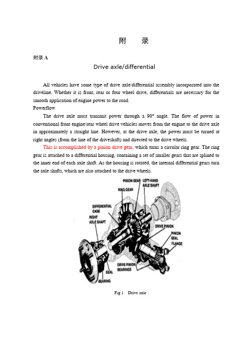
附录附录ADrive axle/differentialAll vehicles have some type of drive axle/differential assembly incorporated into the driveline. Whether it is front, rear or four wheel drive, differentials are necessary for the smooth application of engine power to the road.PowerflowThe drive axle must transmit power through a 90°angle. The flow of power in conventional front engine/rear wheel drive vehicles moves from the engine to the drive axle in approximately a straight line. However, at the drive axle, the power must be turned at right angles (from the line of the driveshaft) and directed to the drive wheels.This is accomplished by a pinion drive gear, which turns a circular ring gear. The ring gear is attached to a differential housing, containing a set of smaller gears that are splined to the inner end of each axle shaft. As the housing is rotated, the internal differential gears turn the axle shafts, which are also attached to the drive wheels.Fig 1 Drive axleRear-wheel driveRear-wheel-drive vehicles are mostly trucks, very large sedans and many sports car and coupe models. The typical rear wheel drive vehicle uses a front mounted engine and transmission assemblies with a driveshaft coupling the transmission to the rear drive axle. Drive in through the layout of the bridge, the bridge drive shaft arranged vertically in the same vertical plane, and not the drive axle shaft, respectively, in their own sub-actuator with a direct connection, but the actuator is located at the front or the back of the adjacent shaft of the two bridges is arranged in series. Vehicle before and after the two ends of the driving force of the drive axle, is the sub-actuator and the transmission through the middle of the bridge. The advantage is not only a reduction of the number of drive shaft, and raise the driving axle of the common parts of each other, and to simplify the structure, reduces the volume and quality.Fig 2 Rear-wheel-drive axleSome vehicles do not follow this typical example. Such as the older Porsche or Volkswagen vehicles which were rear engine, rear drive. These vehicles use a rear mounted transaxle with halfshafts connected to the drive wheels. Also, some vehicles were produced with a front engine, rear transaxle setup with a driveshaft connecting the engine to the transaxle, and halfshafts linking the transaxle to the drive wheels.Differential operationIn order to remove the wheel around in the kinematics due to the lack of co-ordination about the wheel diameter arising from a different or the same rolling radius of wheel travel required, inter-wheel motor vehicles are equipped with about differential, the latter to ensure that the car driver Bridge on both sides of the wheel when in range with a trip to the characteristics of rotating at different speeds to meet the requirements of the vehicle kinematics.Fig 3 Principle of differentialThe accompanying illustration has been provided to help understand how this occurs.1.The drive pinion, which is turned by the driveshaft, turns the ring gear.2.The ring gear, which is attached to the differential case, turns the case.3.The pinion shaft, located in a bore in the differential case, is at right angles to the axle shafts and turns with the case.4.The differential pinion (drive) gears are mounted on the pinion shaft and rotate with the shaft .5.Differential side gears (driven gears) are meshed with the pinion gears and turn with the differential housing and ring gear as a unit.6.The side gears are splined to the inner ends of the axle shafts and rotate the shafts as the housing turns.7.When both wheels have equal traction, the pinion gears do not rotate on the pinion shaft, since the input force of the pinion gears is divided equally between the two side gears.8.When it is necessary to turn a corner, the differential gearing becomes effective and allows the axle shafts to rotate at different speeds .Open-wheel differential on each general use the same amount of torque. To determine the size of the wheel torque to bear two factors: equipment and friction. In dry conditions, when a lot of friction, the wheel bearing torque by engine size and gear restrictions are hours in the friction (such as driving on ice), is restricted to a maximum torque, so that vehicles will not spin round. So even if the car can produce more torque, but also need to have sufficient traction to transfer torque to the ground. If you increase the throttle after the wheels slip, it will only make the wheels spin faster.Limited-slip and locking differential operationFig 5 Limited-slip differentialDifferential settlement of a car in the uneven road surface and steering wheel-driven speedat about the different requirements; but is followed by the existence of differential in theside car wheel skid can not be effective when the power transmission, that is, the wheel slipcan not produce the driving force, rather than spin the wheel and does not have enoughtorque. Good non-slip differential settlement of the car wheels skid on the side of the powertransmission when the issue, that is, locking differential, so that no longer serve a usefuldifferential right and left sides of the wheel can be the same torque.Limited-slip and locking differential operation can be divided into two major categories:(1) mandatory locking type in ordinary differential locking enforcement agencies toincrease, when the side of the wheel skid occurs, the driver can be electric, pneumatic ormechanical means to manipulate the locking body meshing sets of DIP Shell will be withthe axle differential lock into one, thus the temporary loss of differential role. Relatively simple structure in this way, but it must be operated by the driver, and good roads to stop locking and restore the role of differential.(2) self-locking differential installed in the oil viscosity or friction clutch coupling, when the side of the wheel skid occurs when both sides of the axle speed difference there, coupling or clutch friction resistance on the automatic, to make certain the other side of the wheel drive torque and the car continued to travel. When there is no speed difference on both sides of the wheel, the frictional resistance disappeared, the role of automatic restoration of differentials. More complicated structure in this way, but do not require drivers to operate. Has been increasingly applied in the car. About non-slip differential, not only used for the differential between the wheels, but also for all-wheel drive vehicle inter-axle differential/.Gear ratioThe drive axle of a vehicle is said to have a certain axle ratio. This number (usually a whole number and a decimal fraction) is actually a comparison of the number of gear teeth on the ring gear and the pinion gear. For example, a 4.11 rear means that theoretically, there are 4.11 teeth on the ring gear for each tooth on the pinion gear or, put another way, the driveshaft must turn 4.11 times to turn the wheels once. The role of the final drive is to reduce the speed from the drive shaft, thereby increasing the torque. Lord of the reduction ratio reducer, a driving force for car performance and fuel economy have a greater impact. In general, the more reduction ratio the greater the acceleration and climbing ability, and relatively poor fuel economy. However, if it is too large, it can not play the full power of the engine to achieve the proper speed. The main reduction ratio is more Smaller ,the speed is higher, fuel economy is better, but the acceleration and climbing ability will be poor.附录B驱动桥和差速器所有的汽车都装有不同类型的驱动桥和差速器来驱动汽车行驶。
中英文文献翻译—驱动桥和差速器概述

附录A 英文文献Drive axle/differentialAll vehicles have some type of drive axle/differential assembly incorporated into the driveline. Whether it is front, rear or four wheel drive, differentials are necessary for the smooth application of engine power to the road.PowerflowThe drive axle must transmit power through a 90°angle. The flow of power in conventional front engine/rear wheel drive vehicles moves from the engine to the drive axle in approximately a straight line. However, at the drive axle, the power must be turned at right angles (from the line of the driveshaft) and directed to the drive wheels.This is accomplished by a pinion drive gear, which turns a circular ring gear. The ring gear is attached to a differential housing, containing a set of smaller gears that are splined to the inner end of each axle shaft. As the housing is rotated, the internal differential gears turn the axle shafts, which are also attached to the drive wheels.Rear-wheel driveRear-wheel-drive vehicles are mostly trucks, very large sedans and many sports car and coupe models. The typical rear wheel drive vehicle uses a front mounted engine and transmission assemblies with a driveshaft coupling the transmission to the rear drive axle. Drive in through the layout of the bridge, the bridge drive shaft arranged vertically in the same vertical plane, and not the drive axle shaft, respectively, in their own sub-actuator with a direct connection, but the actuator is located at the front or the back of the adjacent shaft of the two bridges is arranged in series. Vehicle before and after the two ends of the driving force of the drive axle, is the sub-actuator and the transmission through the middle of the bridge. The advantage is not only a reduction of the number of drive shaft, and raise the driving axle of the common parts of each other, and to simplify the structure, reduces the volume and quality.Some vehicles do not follow this typical example. Such as the older Porsche or Volkswagen vehicles which were rear engine, rear drive. These vehicles use a rear mounted transaxle with halfshafts connected to the drive wheels. Also, some vehicles were produced with a front engine, rear transaxle setup with a driveshaft connecting the engine to the transaxle, and halfshafts linking the transaxle to the drive wheels.Differential operationIn order to remove the wheel around in the kinematics due to the lack of co-ordination about the wheel diameter arising from a different or the same rolling radius of wheel travel required, inter-wheel motor vehicles are equipped with about differential, the latter to ensure that the car driver Bridge on both sides of the wheel when in range with a trip to the characteristics of rotating at different speeds to meet the requirements of the vehicle kinematics.The accompanying illustration has been provided to help understand how this occurs.1.The drive pinion, which is turned by the driveshaft, turns the ring gear.2.The ring gear, which is attached to the differential case, turns the case.3.The pinion shaft, located in a bore in the differential case, is at right angles to the axle shafts and turns with the case.4.The differential pinion (drive) gears are mounted on the pinion shaft and rotate with the shaft .5.Differential side gears (driven gears) are meshed with the pinion gears and turn with the differential housing and ring gear as a unit.6.The side gears are splined to the inner ends of the axle shafts and rotate the shafts as the housing turns.7.When both wheels have equal traction, the pinion gears do not rotate on the pinion shaft, since the input force of the pinion gears is divided equally between the two side gears.8.When it is necessary to turn a corner, the differential gearing becomes effective and allows the axle shafts to rotate at different speeds .Open-wheel differential on each general use the same amount of torque. To determine the size of the wheel torque to bear two factors: equipment and friction. In dry conditions, when a lot of friction, the wheel bearing torque by engine size and gear restrictions are hours in the friction (such as driving on ice), is restricted to a maximum torque, so that vehicles will not spin round. So even if the car can produce more torque, but also need to have sufficient traction to transfer torque to the ground. If you increase the throttle after the wheels slip, it will only make the wheels spin faster.Limited-slip and locking differential operationDifferential settlement of a car in the uneven road surface and steering wheel-driven speed at about the different requirements; but is followed by the existence of differential in the side car wheel skid can not be effective when the power transmission, that is, the wheel slip can not produce the driving force, rather than spin the wheel and does not have enough torque. Good non-slip differential settlement of the car wheels skid on the side of the power transmission when the issue, that is, locking differential, so that no longer serve a useful differential right and left sides of the wheel can be the same torque.Limited-slip and locking differential operation can be divided into two majorcategories:(1) mandatory locking type in ordinary differential locking enforcement agencies to increase, when the side of the wheel skid occurs, the driver can be electric, pneumatic or mechanical means to manipulate the locking body meshing sets of DIP Shell will be with the axle differential lock into one, thus the temporary loss of differential role. Relatively simple structure in this way, but it must be operated by the driver, and good roads to stop locking and restore the role of differential.(2) self-locking differential installed in the oil viscosity or friction clutch coupling, when the side of the wheel skid occurs when both sides of the axle speed difference there, coupling or clutch friction resistance on the automatic, to make certain the other side of the wheel drive torque and the car continued to travel. When there is no speed difference on both sides of the wheel, the frictional resistance disappeared, the role of automatic restoration of differentials. More complicated structure in this way, but do not require drivers to operate. Has been increasingly applied in the car. About non-slip differential, not only used for the differential between the wheels, but also for all-wheel drive vehicle inter-axle differential/.Gear ratioThe drive axle of a vehicle is said to have a certain axle ratio. This number (usually a whole number and a decimal fraction) is actually a comparison of the number of gear teeth on the ring gear and the pinion gear. For example, a 5.12 rear means that theoretically, there are5.12 teeth on the ring gear for each tooth on the pinion gear or, put another way, the driveshaft must turn 5.12 times to turn the wheels once. The role of the final drive is to reduce the speed from the drive shaft, thereby increasing the torque. Lord of the reduction ratio reducer, a driving force for car performance and fuel economy have a greater impact. In general, the more reduction ratio the greater the acceleration and climbing ability, and relatively poor fuel economy. However, if it is too large, it can not play the full power of the engine to achieve the proper speed. The main reduction ratio is more Smaller ,the speed is higher, fuel economy is better, but the acceleration and climbing ability will be poor.附录B 文献翻译驱动桥和差速器所有的汽车都装有不同类型的驱动桥和差速器来驱动汽车行驶。
差速器外文文献
差速器外文By ordinary differential planetary gear, the planet round rack (differential shell) and half axle gears, etc parts. By the power of the engine, direct drive shaft into differential planetary wheel frame, again by the planets wheel drive left, right, two half shaft are respectively driven wheels left and right. Differential design requirements meet: (left) + (right shaft speed shaft speed)= 2 (planets wheel frame speed). When the automobile moher, left, right wheel and planetary wheel frame three speed equal in balance, while in the car when turning three equilibrium state is destroyed, cause the medial wheel speed decreases, and the lateral wheel RPM increases。
Automotive differential is driven axle Lord pieces. Its function is to both sides half shaft transmission power, while allowing both sides half shaft in different speed rotating, satisfy both sides wheel as pure rolling forms do isometric driving, reducing tire and the surface friction。
差速器外文文献
差速器外文By ordinary differential planetary gear, the planet round rack (differential shell) and half axle gears, etc parts。
By the power of the engine, direct drive shaft into differential planetary wheel frame, again by the planets wheel drive left, right, two half shaft are respectively driven wheels left and right。
Differential design requirements meet: (left) + (right shaft speed shaft speed) = 2 (planets wheel frame speed). When the automobile moher, left, right wheel and planetary wheel frame three speed equal in balance, while in the car when turning three equilibrium state is destroyed, cause the medial wheel speed decreases, and the lateral wheel RPM increases。
Automotive differential is driven axle Lord pieces。
Its function is to both sides half shaft transmission power, while allowing both sides half shaft in different speed rotating, satisfy both sides wheel as pure rolling forms do isometric driving, reducing tire and the surface friction.Differential this adjustment is automatic, here involves "minimal energy consumption principle", namely earth all objects are inclined to consumption minimum state. For example a grain of beans into a bowl, beans will automatically stays in the bowl bottom and never stay in bowl wall, because bowl bottom is lowest energy position (potential), it automatically select static (minimum) without constantly kinetic energy movement。
差速器外文文献
差速器外文By ordinary differential planetary gear, the planet round rack (differential shell) and half axle gears, etc parts. By the power of the engine, direct drive shaft into differential planetary wheel frame, again by the planets wheel drive left, right, two half shaft are respectively driven wheels left and right. Differential design requirements meet: (left) + (right shaft speed shaft speed) = 2 (planets wheel frame speed). When the automobile moher, left, right wheel and planetary wheel frame three speed equal in balance, while in the car when turning three equilibrium state is destroyed, cause the medial wheel speed decreases, and the lateral wheel RPM increases.Automotive differential is driven axle Lord pieces. Its function is to both sides half shaft transmission power, while allowing both sides half shaft in different speed rotating, satisfy both sides wheel as pure rolling forms do isometric driving, reducing tire and the surface friction.Differential this adjustment is automatic, here involves "minimal energy consumption principle", namely earth all objects are inclined to consumption minimum state. For example a grain of beans into a bowl, beans will automatically stays in the bowl bottom and never stay in bowl wall, because bowl bottom is lowest energy position (potential), it automatically select static (minimum) without constantly kinetic energy movement. In the same way, Wheel in cornering would also automatically tendency of the lowest energy consumption in accordance with state, automatically turning radius adjusting right wheels speed.When cornering, due to the lateral friction wheel dragged phenomenon, medial wheel have slip phenomenon, two driving wheel now can produce two opposite direction of additional force, as a result of "minimal energy consumption principle", which inevitably leads on both sides of the wheel speed difference, thus destroyed three balance relationship, and through the half shaft are reflected in half axle gear, forcing planetary gear produce rotation, make the lateral half shaft speed faster, medial half axle planetismal, thus realize both sides wheel speed difference.If the drive wheels on either side of the drive axle shaft to the use of a whole rigid connection, the two wheels can only at the same Angle rotation. So, when the vehicle steering wheel drive, due to the lateral than medial wheels moved across the distance is big, will make the lateral wheels in rolling produced simultaneously slippery procrastinate, and medial wheels in rolling produced simultaneously slip. Even the car run straight road gravamen, because although pavement straight but tyres or rolling radius range (tyre manufacture error, wear different, by the uneven or pneumatic ranging caused by the wheels of sliding).Wheel when not only aggravate sliding tire wear, increase power and fuel consumption, still can make the vehicle steering difficulties, braking performance becomes poor. For the wheel as far as possible will not occur in the structure of sliding, must guarantee the wheels can come with different Angle rotation.Axis between differential: usually driven wheel bearings for support on spindle, enable to any Angle rotation, and drive wheels respectively with two root half axle rigid connection, in between two root half shaft with differential. This differential also called shaft between differential.slowly, right wheels faster, with different speed to compensate for the distance of the differences.If after axles make it a whole, he couldn't do it on both sides of the wheel speed difference, namely can't do an automatic adjustment. In order to solve this problem, as early as in a hundred years ago, France Renault automotive company founder luis Renault will design a differential in this thing.Modern vehicles on the differential usually according to its work characteristics into gear type differential and slip differential two kinds big.The structure of the Cherokee open-die differential is typical of planetary gear set structure, only the sun wheel and outside the pinion gear ring are the same. In this planetary gear set, driving gear is planet shelf, passive round is two SUNS wheel. Through the planetary gear set the transmission properties we know, if the planet shelf as ZhuDongZhou, two SUNS wheel speed and rotation direction is not affirmatory, even two SUNS wheel rotation direction is the opposite.Vehicle condition, this differential moher, feature is to two and a half shaft transmission torque of the same. In a driving wheel impending case, if the drive shaft rotation, have adhesion is uniform the driving wheels of driving force, if there is no drive shaft rotation is accelerated, have adhesion the driving wheels driving force equals impending wheel Angle acceleration and rotary inertia of the product.Vehicle turning tires don't skid condition, connect the two halves of the differential shaft torque direction is opposite, give the vehicle driving forward, and only the inside of the wheel, the planet shelf and medial sun round by the isokinetic transmission between became deceleration transmission, driving sensation is accelerated speed corners than straight more powerful.The advantages of open-die differential is installed in the pavement turned driving on the best effect. Weakness is in a driving wheel loss adhesion, under the situation of another nor driving force.Open-die differential is the suitable scope that all paving road traffic, front axle and rear axle driver drive can be installed.2. Limited slip differentialLimited slip differential used for parts make up open-die differential transmission in off-road defects, it is in the open differential institution improved, and the differential shell side increase friction between gear piece, corresponding to the planetary gear set speaking, is the planet shelf and the sun round between increased friction slices, increase the sun wheel and planet shelf free rotating resistance torque.Limited slip differential provide additional torque, and friction slices transfer of power and two driving wheel rotation difference of concerned.In open-die differential structure to improve on LSD, cannot produce 100% limited slip, because the limited slip coefficient, the higher the vehicles to the characteristics of the poor.LSD have open-die differential transmission characteristics and mechanical structure. Advantage is to provide certain limited slip torque, defect is turning performance becomes poor, friction slices limited life.LSD is the suitable scope paving road surface and mild off-road. Usually used for the drive. Former drove generally does not installed, because LSD interfere steering, limited slip coefficient, the greater the steering the more difficult.Three. The lock type differential (mechanical locking check, electric the lock, pneumatic locking check)In order to guarantee the off-road vehicles in complex conditions, driving performance through certain mechanical structure of the differential locked achieve two half axle synchronous rotation. Through the analysis of planetary gear set is the planetary gear set of gear mechanisms locked, guarantee the planet shelf wheel with the sun, and two SUNS round between the transmission ratio between is 1:1. Can the sun to the wheel and planet shelf the lock, can put the planet shelf and planetary gear locked, still can put two SUNS wheel locked.The lock type differential, without the lock, its transmission characteristics and open-die differential exactly the same as that in the lock, under the situation of transmission ratio was fixed for 1:1.The advantages of this differential in off-road self-evident that provides the biggest drawback is the driving force, the differential lock up the situation, vehicle steering extremely difficult, Existing single wheel inherit engine 100% torque possible, half shaft will because torque excessive deformation or break, Vehicles in the process of steering bearings, two and a half by opposite torque, if both sides tires adhesion are large, would wring half axle. Moreover, this kind of differentials, the vehicle process execution lock up the action will produce larger noise.Four. Electronic differentials lockElectronic differentials lock and the aforesaid compared, without changing the structure and characteristics of open-die differential, but use ABS or EBD systemto implement unilateral braking skid wheels movement, limit of two driving wheel rotation difference, guarantee the drive wheels momentum.Advantages: good safety, won't damaged vehicle. Faults: need ABS and costly; EBD system, In the harsh off-road conditions, electronic product reliability as mechanical products; Unilateral wheel driving force, as the lock type differential. 1, gear type differential:When driving wheel rotation difference exists about when, differential assigned to slow turns driving wheel torque is greater than turn fast driving wheel torque. This kind of differential torque partitioning characteristics can satisfy the car in good pavement moving. But when the automobile in bad the road, but serious influence through capacity. E.g. when a car driving wheel into muddy road, although another driving wheel in good road, the car was often cannot advance (known as slips). At this point in the muddy road on the driving wheels in-situ slip, in good road wheels is motionless. This is because in the muddy road wheels and road surface adhesion between the lesser, road only through this round of half-and-half shaft role of smaller reaction torque, therefore differential assigned to this round of torque also small, although another driving wheel and better road to improve adhesion of the larger, but because average distribution characteristics of torque, which make this drive wheels can only also assigned to the drive wheels with slip equal amounts of torque, so that the driving force to overcome driving resistance, cars can't advance and motivation is expended in slip driving wheel. At this time to floor not only made the car ahead, instead of waste fuel, accelerate parts wear, especially tire wear is intensified. Effective solutions are: slicer slip driving wheel under the mud or in this wheel mat dry soil, gravel, branches, hay, etc. 2, slip differential:In order to improve the car in a bad way through capacity, some off-road vehicle and limousines screwup slip differential. Slip differential characteristics are, when driving wheel in a bad way side slip, can make the most or all torque in good road to the driving wheels, to take full advantage of the drive wheels adhesion to generate enough force, that car start or continue to drive.1. Differential shell there cannot be any properties of crack, shell and planetary gear gaskets, differential half axle gear contact between, should be smooth without groove, If there is a slight groove or wear, can continue to use after grinding, otherwise must be changed or be repaired.2 the planetary gear differential shell and planetary gear wheel when the fitting clearance must not be more than 0.1-0.15 mm, half axle gear shaft neck and shell with holes for clearance fit, should have no obvious loose feeling, otherwise desert must be changed or repair.。
- 1、下载文档前请自行甄别文档内容的完整性,平台不提供额外的编辑、内容补充、找答案等附加服务。
- 2、"仅部分预览"的文档,不可在线预览部分如存在完整性等问题,可反馈申请退款(可完整预览的文档不适用该条件!)。
- 3、如文档侵犯您的权益,请联系客服反馈,我们会尽快为您处理(人工客服工作时间:9:00-18:30)。
外文翻译(汽车差速器)Failure analysis of an automobile differential pinion shaftAbstractDifferential is used to decrease the speed and to provide moment increase for transmitting the movement coming from the engine to the wheels by turning it according to the suitable angle in vehicles and to provide that inner and outer wheels turn differently. Pinion gear and shaft at the entrance are manufactured as a single part whereas they are in different forms according to automobile types. Mirror gear which will work with this gear should become familiar before the assembly. In case of any breakdown, they should be changed as a pair. Generally, in these systems there are wear damages in gears. The gear inspected in thisstudy has damage as a form of shaft fracture.In this study, failure analysis of the differential pinion shaft is carried out. Mechanical characteristics of the material are obtained first. Then, the microstructure and chemical compositions are determined. Some fractographic studies are carried out to asses the fatigue and fracture conditions.Keywords: Differential; Fracture; Power transfer; Pinion shaft1. IntroductionThe final-drive gears may be directly or indirectly driven from the output gearing of the gearbox. Directly driven final drives are used when the engine and transmission units are combined together to form anintegral construction. Indirectly driven final drives are used at the rear of the vehicle being either sprung and attached to the body structure or unsprung and incorporated in the rear-axle casing. Thefinal-drive gears are used in the transmission system for the following reasons [1]:(a) to redirect the drive from the gearbox or propeller shaftthrough 90? and,(b) to provide a permanent gear reduction between the engine and the driving road-wheels.In vehicles, differential is the main part which transmits the movement coming from the engine to the wheels. On a smooth road, the movement comes to both wheels evenly. The inner wheel should turn less and the outer wheel should turn more to do the turning without lateral slipping and being flung. Differential, which is generally placed in the middle part of the rear bridge, consists of pinion gear, mirror gear, differential box, two axle gear and two pinion spider gears.A schematic illustration of a differential is given in Fig. 1. The technical drawing of the fractured pinion shaft is also given in Fig. 2. Fig. 3 shows the photograph of the fractured pinion shaft and the fracture section is indicated.In differentials, mirror and pinion gear are made to get used to each other during manufacturing and the same serial number is given. Both of them are changed on condition that there are any problems. Inthese systems, the common damage is the wear of gears [2–4]. In this study, the pinion shaft of the differential of aminibus has been inspected. The minibus is a diesel vehicle drivenat the rear axle and has a passenger capacity of 15 people. Maximum engine power is 90/4000 HP/rpm, and maximum torque is 205/1600 Nm/rpm. Its transmission box has manual system (5 forward, 1 back). The damage was caused by stopping and starting the minibus at a traffic lights. In this differential, entrance shaft which carries the pinion gear was broken. Various studies have been made to determine the type and possible reasons of the damage.These are:studies carried out to determine the material of the shaft;studies carried out to determine the micro-structure;studies related to the fracture surface.There is a closer photograph of the fractured surfaces and fracture area in Fig. 4. The fracture was caused by taking out circular mark gear seen in the middle of surfaces.Fig. 1. Schematic of the analysed differential.Fig. 2. Technical drawing of the analysed pinion shaftFig. 3. The picture of the undamaged differential pinion analysed in the studyFig. 4. Photographs of failed shaft2. Experimental procedureSpecimens extracted from the shaft were subjected to various tests including hardness tests and metallographic and scanning electronmicroscopy as well as the determination of chemical composition. All tests were carried out at room temperature.2.1. Chemical and metallurgical analysisChemical analysis of the fractured differential material was carried out using a spectrometer. The chemical composition of the material is given in Table 1. Chemical composition shows that the material is a low alloy carburising steel of the AISI 8620 type.Hardenability of this steel is very low because of low carbon proportion. Therefore, surface area becomes hard and highly enduring, and inner areas becomes tough by increasing carbon proportion on the surface area with cementation operation. This is the kind of steel which is generally used in mechanical parts subjected do torsion and bending. High resistance is obtained on the surface and high fatigue endurance value can be obtained with compressive residual stress by making the surface harder [5–7].In which alloy elements distribute themselves in carbon steels depends primarily on the compound- and carbide-forming tendencies of each element. Nickel dissolves in the a ferrite of the steel since it has less tendency to form carbides than iron. Silicon combines to a limited extent with the oxygen present in the steel to form nonmetallic inclusions but otherwise dissolves in the ferrite. Most of the manganese added to carbon steels dissolves in the ferrite. Chromium, which has a somewhat stronger carbide-forming tendency than iron, partitions between the ferrite and carbide phases. The distribution ofchromium depends on the amount of carbon present and if other stronger carbide-forming elements such as titanium and columbium are absent. Tungsten and molybdenum combine with carbon to form carbides if there is sufficient carbon present and if other stronger carbide-forming elements such as titanium and columbium are absent. Manganese and nickel lower the eutectoid temperature [8].Preliminary micro structural examination of the failed differential material is shown in Fig. 5. It can be seen that the material has a mixed structure in which some ferrite exist probably as a result of slow cooling and high Si content. High Si content in this type of steel improves the heat treatment susceptibility as well as an improvement of yield strength and maximum stress without any reduction of ductility [9]. If the microstructure cannot be inverted to martensite by quenching, a reduction of fatigue limit is observed.Table 1Chemical analysis of the pinion gear material (wt%)Fe C Si Mn P S Cr Mo Ni 96.92 0.235 0.252 0.786 0.044 0.016 0.4810.151 0.517 and fracture surfaces.Fig. 5. Micro structure of the material (200?).There are areas with carbon phase in Fig. 5(a). There is the transition boundary of carburisation in Fig. 5(b) and (c) shows thematrix region without carburisation. As far as it is seen in these photographs, the piece was first carburised, then the quenching operation was done and than tempered. This situation can be understood from blind martensite plates.2.2. Hardness testsThe hardness measurements are carried out by a MetTest-HT type computer integrated hardness tester. The load is 1471 N. The medium hardness value of the interior regions is obtained as 43 HRC. Micro hardness measurements have been made to determine the chance of hardness values along the cross-section because of the hardening of surface area due to carburisation. The results of Vickers hardness measurement undera load of 4.903 N are illustrated in Table 2.2.3. Inspection of the fractureThe direct observations of the piece with fractured surfaces and SEM analyses are given in this chapter. The crack started because of a possible problem in the bottom of notch caused the shaft to be broken completely. The crack started on the outer part, after some time it continued beyond the centre and there was only a little part left. And this part was broken statically during sudden starting of the vehicle at the traffic lights. As a characteristic of the fatigue fracture, there are two regions in the fractured surface. These are a smooth surface created by crack propagation and a rough surface created by sudden fracture. These two regions can be seen clearly for the entire problemas in Fig. 4. The fatigue crack propagation region covers more than 80% of the cross-section.Table 2Micro hardness values Distance from surface (lm) 50 100 200 400 Center Values HV (4903N) 588 410 293 286 263Fig.Fig. 6. SEM image of the fracture surface showing the ductile shear.Fig. 7. SEM image of the fracture surface showing the beach marks of the fatigue crack propagation.Shaft works under the effect of bending, torsion and axial forces which affect repeatedly depending on the usage place. There is a sharpfillet at level on the fractured section. For this reason, stress concentration factors of the area have been determined. Kt = 2.4 value (for bending and tension) and Kt = 1.9 value (for torsion) have been acquired according to calculations. These are quite high values for areas exposed to combined loading.These observations and analysis show that the piece was broken under the influence of torsion with low nominal stresses and medium stress concentration [10].The scanning electron microscopy shows that the fracture has taken place in a ductile manner (Fig. 6). There are some shear lips in the crack propagation region which is a glue of the plastic shear deformations. Fig. 7 shows the beach marks of the fatigue crack propagation. The distance between any two lines is nearly 133 nm.3. ConclusionsA failed differential pinion shaft is analysed in this study. The pinion shaft is produced from AISI 8620 low carbon carburising steel which had a carburising, quenching and tempering heat treatment process. Mechanical properties, micro structural properties, chemical compositions and fractographic analyses are carried out to determine the possible fracture reasons of the component. As a conclusion, the following statements can be drawn:The fracture has taken place at a region having a high stress concentration by a fatigue procedure under a combined bending, torsion and axial stresses having highly reversible nature.The crack of the fracture is initiated probably at a material defect region at the critical location.The fracture is taken place in a ductile manner.Possible later failures may easily be prevented by reducing thestress concentration at the critical location.AcknowledgementThe author is very indebted to Prof. S. Tasgetiren for his adviceand recommendations during the study.H. Bayrakceken / Engineering Failure Analysis 13 (2006) 1422–1428References[1] Heisler H. Vehicle and engine technology. 2nd ed. London: SAE International; 1999.[2] Makevet E, Roman I. Failure analysis of a final drivetransmission in off-road vehicles. Eng Failure Anal 2002;9:579–92.[3] Orhan S, Aktu?rk N. Determination of physical faults in gearbox through vibration analysis. J Fac Eng Arch Gazi University 106. 2003;18(3):97–[4] Tas getiren S, Aslantas K, Ucun I. Effect of press-fitting pressure on the fatigue damages of root in spur gears. Technol Res: EJMT 2004;2:21–9.[5] Nanawarea GK, Pableb MJ. Failures of rear axle shafts of 575 DI tractors. Eng Failure Anal 2003;10:719–24.[6] Aslantas K, Tas getiren S. A study of spur gear pittingformation and life prediction. Wear 2004;257:1167–75.[7] Savas V, O? zek C. Investigation of the distribution of temperature on a shaft with respect to the deflection. Technol Res: EJMT 2005;1:33–8.[8] Smith FW. Principles of materials science and engineering. 3rd ed. USA: McGraw-Hill Series; 1996. p. 517–18.[9] ASM metal handbook, vol. 1. Properties and selection, irons, steels, and high performance alloys; 1991.[10] Voort GFV. Visual examination and light microscopy. ASM handbook metallography and microstructures. Materials Park (OH): ASM International; 1991. p. 100–65.汽车差速器小齿轮轴的失效分析摘要差速器的作用是根据车辆合适的角度, 通过将运动转向, 为运动传输减速或者提供瞬间加速, 这个运动来自引擎, 到车轮去, 使内外车轮转动不同。