stm32定时器指南
STM32定时器配置(TIM1、TIM2、TIM3、TIM4、TIM5、TIM8)高级定时。。。
STM32定时器配置(TIM1、TIM2、TIM3、TIM4、TIM5、TIM8)⾼级定时。
⽂章结构:——> ⼀、定时器基本介绍——> ⼆、普通定时器详细介绍TIM2-TIM5——> 三、定时器代码实例⼀、定时器基本介绍之前有⽤过野⽕的学习板上⾯讲解很详细,所以直接上野⽕官⽅的资料吧,作为学习参考笔记发出来⼆、普通定时器详细介绍TIM2-TIM52.1 时钟来源计数器时钟可以由下列时钟源提供:·内部时钟(CK_INT)·外部时钟模式1:外部输⼊脚(TIx)·外部时钟模式2:外部触发输⼊(ETR)·内部触发输⼊(ITRx):使⽤⼀个定时器作为另⼀个定时器的预分频器,如可以配置⼀个定时器Timer1⽽作为另⼀个定时器Timer2的预分频器。
由于今天的学习是最基本的定时功能,所以采⽤内部时钟。
TIM2-TIM5的时钟不是直接来⾃于APB1,⽽是来⾃于输⼊为APB1的⼀个倍频器。
这个倍频器的作⽤是:当APB1的预分频系数为1时,这个倍频器不起作⽤,定时器的时钟频率等于APB1的频率(36MHZ);当APB1的预分频系数为其他数值时(即预分频系数为2、4、8或16),这个倍频器起作⽤,定时器的时钟频率等于APB1的频率的2倍。
{假如APB1预分频为2(变成36MHZ),则定时器TIM2-5的时钟倍频器起作⽤,将变成2倍的APB1(2x36MHZ)将为72MHZ给定时器提供时钟脉冲。
⼀般APB1和APB2的RCC时钟配置放在初始化函数中例如下⾯的void RCC_Configuration(void)配置函数所⽰,将APB1进⾏2分频,导致TIM2时钟变为72MHZ输⼊。
如果是1分频则会是36MHZ输⼊,如果4分频:CKINT=72MHZ/4x2=36MHZ; 8分频:CKINT=72MHZ/8x2=18MHZ;16分频:CKINT=72MHZ/16x2=9MHZ}1//系统时钟初始化配置2void RCC_Configuration(void)3 {4//定义错误状态变量5 ErrorStatus HSEStartUpStatus;6//将RCC寄存器重新设置为默认值7 RCC_DeInit();8//打开外部⾼速时钟晶振9 RCC_HSEConfig(RCC_HSE_ON);10//等待外部⾼速时钟晶振⼯作11 HSEStartUpStatus = RCC_WaitForHSEStartUp();12if(HSEStartUpStatus == SUCCESS)13 {14//设置AHB时钟(HCLK)为系统时钟15 RCC_HCLKConfig(RCC_SYSCLK_Div1);16//设置⾼速AHB时钟(APB2)为HCLK时钟17 RCC_PCLK2Config(RCC_HCLK_Div1);18 //设置低速AHB时钟(APB1)为HCLK的2分频(TIM2-TIM5输⼊TIMxCLK频率将为72MHZ/2x2=72MHZ输⼊)19 RCC_PCLK1Config(RCC_HCLK_Div2);20//设置FLASH代码延时21 FLASH_SetLatency(FLASH_Latency_2);22//使能预取指缓存23 FLASH_PrefetchBufferCmd(FLASH_PrefetchBuffer_Enable);24//设置PLL时钟,为HSE的9倍频 8MHz * 9 = 72MHz25 RCC_PLLConfig(RCC_PLLSource_HSE_Div1, RCC_PLLMul_9);26//使能PLL27 RCC_PLLCmd(ENABLE);28//等待PLL准备就绪29while(RCC_GetFlagStatus(RCC_FLAG_PLLRDY) == RESET);30//设置PLL为系统时钟源31 RCC_SYSCLKConfig(RCC_SYSCLKSource_PLLCLK);32//判断PLL是否是系统时钟33while(RCC_GetSYSCLKSource() != 0x08);34 }35//允许TIM2的时钟36 RCC_APB1PeriphClockCmd(RCC_APB1Periph_TIM2,ENABLE);37//允许GPIO的时钟38 RCC_APB2PeriphClockCmd(RCC_APB2Periph_GPIOB,ENABLE);39 }APB1的分频在STM32_SYSTICK的学习笔记中有详细描述。
stm32 timer 用法
stm32 timer 用法摘要:1.引言2.STM32定时器简介3.STM32定时器工作原理4.STM32定时器配置与使用5.STM32定时器应用实例6.总结正文:1.引言STM32是一款广泛应用于嵌入式系统的微控制器,拥有丰富的外设资源。
其中,定时器(Timer)是STM32外设中非常关键的部分,它在系统时钟、输入捕捉、输出比较、PWM等功能中起着举足轻重的作用。
本文将详细介绍STM32定时器的用法。
2.STM32定时器简介STM32定时器主要包括基本定时器(Basic Timer)、高级定时器(Advanced Timer)和看门狗定时器(Watchdog Timer)。
其中,基本定时器主要用于系统时钟的生成和控制;高级定时器具有更多的功能,如输入捕捉、输出比较、PWM等;看门狗定时器用于检测系统的运行状态,防止系统崩溃。
3.STM32定时器工作原理STM32定时器的工作原理主要基于计数器、预分频器和比较器。
计数器用于记录定时器滴答(Tick)的数量;预分频器用于控制定时器滴答频率;比较器用于产生定时器溢出信号。
当定时器溢出时,定时器硬件会自动产生中断,通过编程可以设置相应的中断处理程序,实现特定功能。
4.STM32定时器配置与使用配置STM32定时器主要包括以下步骤:(1)使能定时器:通过设置相应寄存器位,使能定时器;(2)配置定时器工作模式:根据需求选择定时器工作模式,如计数模式、PWM模式等;(3)配置定时器时钟源:选择定时器时钟源,如内部时钟、外部时钟等;(4)配置定时器预分频器:设置定时器预分频器值,以满足定时器滴答频率要求;(5)配置比较器:设置比较器值,以产生定时器溢出信号;(6)配置中断:根据需求配置定时器中断,如使能中断、设置优先级等。
5.STM32定时器应用实例以下是一个简单的STM32定时器应用实例:使用STM32F103C8T6微控制器实现一个LED闪烁的程序。
(1)配置定时器:使能定时器TIM2,设置工作模式为计数模式,时钟源为内部时钟,预分频器值为72000,比较器值为65536。
STM32之TIM通用定时器

STM32之TIM通⽤定时器本⽂介绍如何使⽤STM32标准外设库配置并使⽤定时器,定时器就是设置⼀个计时器,待计时时间到之后产⽣⼀个中断,程序接收到中断之后可以执⾏特定的程序,跟现实中的闹钟功能类似。
与延时功能不同,定时器计时过程中程序可以执⾏其他程序。
最简单直观的应⽤为定时翻转指定IO引脚。
本例程使⽤通⽤定时器TIM3,每100ms翻转GPIOB的Pin5输出,如果该引脚外接有LED灯,可以看到LED灯周期性的闪烁。
STM32F103VE系列共有8个定时器,分为基本定时器、通⽤定时器和⾼级定时器,其中通⽤定时器包括TIM2/3/4/5共4个,如果⼀个定时器不够⽤,可以启动其他⼏个定时器。
本⽂适合对单⽚机及C语⾔有⼀定基础的开发⼈员阅读,MCU使⽤STM32F103VE系列。
TIM通⽤定时器分为两部分,初始化和控制。
1. 初始化分两步:通⽤中断、TIM。
1.1. 通⽤中断:优先级分组、中断源、优先级、使能优先级分组:设定合适的优先级分组中断源:选择指定的TIM中断源:TIM3_IRQn优先级:设定合适的优先级使能:调⽤库函数即可1.2. TIM:时钟、预分频器、定时器周期、分频因⼦、计数模式、初始化定时器、开启定时器中断、使能计数器。
结构体:typedef struct{uint16_t TIM_Prescaler;uint16_t TIM_CounterMode;uint16_t TIM_Period;uint16_t TIM_ClockDivision;uint8_t TIM_RepetitionCounter;} TIM_TimeBaseInitTypeDef;时钟:需要使能定时器时钟//开启定时器时钟,即内部时钟CK_INT=72MRCC_APB1PeriphClockCmd(RCC_APB1Periph_TIM3, ENABLE);预分频器:默认定时器时钟频率为72M,那么预分频器设置为71,那么⼀次计数为1us//时钟预分频数为71,则计数器计数⼀次时间为1usTIM_TimeBaseStructure.TIM_Prescaler = 71;定时器周期:设置为999,那么产⽣⼀次定时器中断的时间为1ms//⾃动重装载寄存器为999,则产⽣⼀次中断时间为1msTIM_TimeBaseStructure.TIM_Period = 1000 - 1;计数模式:⼀般选择向上计数模式// 计数器计数模式,选择向上计数模式TIM_TimeBaseStructure.TIM_CounterMode = TIM_CounterMode_Up;时钟分频因⼦:⼀般选择1分频// 时钟分频因⼦,选择1分频TIM_TimeBaseStructure.TIM_ClockDivision = TIM_CKD_DIV1;重复计数器的值:仅对⾼级定时器有效,⽆需设置初始化定时器:调⽤库函数即可//初始化定时器TIM_TimeBaseInit(TIM3, &TIM_TimeBaseStructure);开启定时器中断//开启计数器中断TIM_ITConfig(TIM3, TIM_IT_Update, ENABLE);使能计数器//使能计数器TIM_Cmd(TIM3, ENABLE);2. 处理2.1. 中断服务函数定时器TIM3的中断服务函数名称为TIM3_IRQHandler ()。
stm32定时器

STM32定时器定时器功能简介区别于SysTick一般只用于系统时钟的计时,STM32的定时器外设功能非常强大。
STM32一共有8个都为16位的定时器。
其中TIM6、TIM7是基本定时器;TIM 2、TIM3、TIM4、TIM5是通用定时器;TIM1和TIM8是高级定时器。
这些定时器使STM32具有定时、信号的频率测量、信号的PWM测量、PWM输出、三相6步电机控制及编码器接口等功能,都是专门为工控领域量身定做的。
定时器工作分析基本定时器基本定时器TIM6和TIM7只具备最基本的定时功能,就是累加的时钟脉冲数超过预定值时,能触发中断或触发DMA请求。
这两个基本定时器使用的时钟源都是TIMxCLK,时钟源经过PSC预分频器输入至脉冲计数器TIMx_CNT,基本定时器只能工作在向上计数模式,在重载寄存器TIMx_ARR中保存的是定时器的溢出值。
工作时,脉冲计数器TIMx_CNT由时钟触发进行计数,当TIMx_CNT的计数值X等于重载寄存器TIMx_ARR中保存的数值N时,产生溢出事件,可触发中断或DMA请求。
然后TIMx_CNT的值重新被置为0,重新向上计数。
通用定时器相比之下,通用定时器TIM2~TIM5就比基本定时器复杂得多了。
除了基本的定时,它主要用在测量输入脉冲的频率、脉冲宽与输出PWM脉冲的场合,还具有编码器的接口。
通用定时器的基本计时功能与基本定时器的工作方式是一样的,同样把时钟源经过预分频器输出到脉冲计数器TIMx_CNT累加,溢出时就产生中断或DMA请求。
而通用定时器比基本定时器多出的强大功能,就是因为通用定时器多出了一种寄存器----捕获/比较寄存器TIMx_CRR(capture/compareregister)它在输入时被用于捕获(存储)输入脉冲在电平发生翻转时脉冲计数器TI Mx_CNT的当前计数值,从而实现脉冲的频率测量;在输出时被用来存储一个脉冲数值,把这个数值用于与脉冲计数器TIMx_CNT的当前计数值进行比较,根据比较结果进行不同的电平输出定时器的时钟源从时钟源方面来说,通用定时器比基本定时器多了一个选择,它可以使用外部脉冲作为定时器的时钟源。
STM32的定时器定时时间计算(计数时间和中断定时时间)

STM32的定时器定时时间计算(计数时间和中断定时时间)时基单元可编程⾼级控制定时器的主要部分是⼀个16位计数器和与其相关的⾃动装载寄存器。
这个计数器可以向上计数、向下计数或者向上向下双向计数。
此计数器时钟由预分频器分频得到。
计数器、⾃动装载寄存器和预分频器寄存器可以由软件读写,即使计数器还在运⾏读写仍然有效。
时基单元包含:●计数器寄存器(TIMx_CNT)●预分频器寄存器 (TIMx_PSC)●⾃动装载寄存器 (TIMx_ARR)●重复次数寄存器 (TIMx_RCR)⾃动装载寄存器是预先装载的,写或读⾃动重装载寄存器将访问预装载寄存器。
根据在TIMx_CR1寄存器中的⾃动装载预装载使能位(ARPE)的设置,预装载寄存器的内容被⽴即或在每次的更新事件UEV时传送到影⼦寄存器。
当计数器达到溢出条件(向下计数时的下溢条件)并当TIMx_CR1寄存器中的UDIS位等于0时,产⽣更新事件。
更新事件也可以由软件产⽣。
随后会详细描述每⼀种配置下更新事件的产⽣。
计数器由预分频器的时钟输出CK_CNT驱动,仅当设置了计数器TIMx_CR1寄存器中的计数器使能位(CEN)时,CK_CNT才有效。
(更多有关使能计数器的细节,请参见控制器的从模式描述)。
注意,在设置了TIMx_CR寄存器的CEN位的⼀个时钟周期后,计数器开始计数。
预分频器描述预分频器可以将计数器的时钟频率按1到65536之间的任意值分频。
它是基于⼀个(在TIMx_PSC寄存器中的)16位寄存器控制的16位计数器。
因为这个控制寄存器带有缓冲器,它能够在运⾏时被改变。
新的预分频器的参数在下⼀次更新事件到来时被采⽤。
尤其注意的是当发⽣⼀个更新事件时,所有的寄存器都被更新,硬件同时(依据URS位)设置更新标志位(TIMx_SR寄存器中的UIF位)。
●重复计数器被重新加载为TIMx_RCR寄存器的内容。
●⾃动装载影⼦寄存器被重新置⼊预装载寄存器的值(TIMx_ARR)。
STM32CUBEMX配置教程(十二)STM32的定时器触发的固定频率ADC采样(使用DMA)
STM32CUBEMX配置教程(十二)STM32的定时器触发的固定频率ADC采样(使用DMA)本教程将向您展示如何使用STM32CubeMX配置定时器触发的固定频率ADC采样,并使用DMA进行数据传输。
此配置可以用于您需要按照固定频率对模拟信号进行采样的应用中。
在开始之前,请确保已安装好STM32CubeMX和相应的IDE(如Keil、IAR等),并且您已熟悉STM32CubeMX的基本使用方法。
以下是配置步骤:1. 打开STM32CubeMX,并选择您的目标MCU型号。
2. 在"Pinout & Configuration"选项卡中,配置定时器和ADC引脚。
a.选择一个定时器,并设置其时钟源和频率。
您可以选择任何一个可用的定时器来触发ADC采样。
b.配置ADC引脚,将其连接到您的模拟信号源。
3. 在"Configuration"选项卡中,配置ADC。
a.启用ADC和DMA控制器。
b.配置ADC分辨率,采样时间和采样周期。
这些参数取决于您的应用需求。
c. 在"Mode"选项中,选择"Continuous Conversion Mode"。
这样ADC将会不断地根据定时器触发进行采样。
d. 启用"DMA Continuous Requests"。
这样当ADC完成一次采样后,DMA控制器将自动将数据传输到内存中。
4. 在"NVIC Settings"选项卡中,启用DMA和ADC中断。
5. 在"Project"选项卡中,选择生成代码所需的IDE和工程路径。
然后单击"Generate Code"按钮生成代码。
现在您已成功配置了定时器触发的固定频率ADC采样,并使用DMA进行数据传输。
您可以在生成的代码中初始化和启用各个模块,并编写相应的中断处理函数来处理DMA和ADC中断。
STM32通用定时器
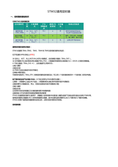
STM32通用定时器一、定时器的基础知识三种STM32定时器区别通用定时器功能特点描述:STM3 的通用 TIMx (TIM2、TIM3、TIM4 和 TIM5)定时器功能特点包括:位于低速的APB1总线上(APB1)16 位向上、向下、向上/向下(中心对齐)计数模式,自动装载计数器(TIMx_CNT)。
16 位可编程(可以实时修改)预分频器(TIMx_PSC),计数器时钟频率的分频系数 为 1~65535 之间的任意数值。
4 个独立通道(TIMx_CH1~4),这些通道可以用来作为:①输入捕获②输出比较③ PWM 生成(边缘或中间对齐模式)④单脉冲模式输出可使用外部信号(TIMx_ETR)控制定时器和定时器互连(可以用 1 个定时器控制另外一个定时器)的同步电路。
如下事件发生时产生中断/DMA(6个独立的IRQ/DMA请求生成器):①更新:计数器向上溢出/向下溢出,计数器初始化(通过软件或者内部/外部触发)②触发事件(计数器启动、停止、初始化或者由内部/外部触发计数)③输入捕获④输出比较⑤支持针对定位的增量(正交)编码器和霍尔传感器电路⑥触发输入作为外部时钟或者按周期的电流管理STM32 的通用定时器可以被用于:测量输入信号的脉冲长度(输入捕获)或者产生输出波形(输出比较和 PWM)等。
使用定时器预分频器和 RCC 时钟控制器预分频器,脉冲长度和波形周期可以在几个微秒到几个毫秒间调整。
STM32 的每个通用定时器都是完全独立的,没有互相共享的任何资源。
定时器框图:倍频得到),外部时钟引脚,可以通过查看数据手册。
也可以是TIMx_CHn,此时主要是实现捕获功能;框图中间的时基单元框图下面左右两部分分别是捕获输入模式和比较输出模式的框图,两者用的是同一引脚,不能同时使用。
二、定时器相关的寄存器和寄存器操作库函数时钟选择, 计数器时钟可以由下列时钟源提供:时钟选择①内部时钟(CK_INT)②外部时钟模式1:外部输入脚(TIx)③外部时钟模式2:外部触发输入(ETR)④内部触发输入(ITRx):使用一个定时器作为另一个定时器的预分频器,如可以配置一个定时器Timer1而作为另一个定时器Timer2的预分频器。
stm32定时器的使用流程

STM32定时器的使用流程1. 简介STM32定时器是STM32系列微控制器中重要的外设之一。
定时器可以用于生成特定的定时器事件,实现计时、测量时间间隔、产生PWM信号等功能。
本文将介绍STM32定时器的使用流程。
2. STM32定时器的基本工作原理STM32定时器通常由一个或多个计数器和若干个通道组成。
计数器用于计算时间的流逝,而通道用于控制输出。
计数器的计数范围和分辨率可以根据需求进行配置。
通常情况下,定时器通过外部时钟源进行计数,也可以使用内部时钟源。
3. STM32定时器的使用流程使用STM32定时器通常需要以下步骤:3.1 初始化定时器在使用定时器之前,需要初始化定时器的相关参数,包括计数器的计数范围、分频系数等。
通常可以通过寄存器的设置来完成初始化工作。
使用HAL库的话,可以使用HAL_TIM_Base_Init()函数进行初始化。
3.2 配置定时器的工作模式定时器可以根据需求配置为不同的工作模式,常见的模式包括单脉冲模式、连续模式、PWM输出模式等。
可以使用TIM_CR1、TIM_CR2等寄存器进行配置。
使用HAL库的话,可以使用相应的函数进行配置。
3.3 配置定时器的中断和DMA定时器可以配置中断和DMA功能,在特定的条件下触发相应的中断或DMA请求。
可以使用TIM_DIER寄存器进行配置。
使用HAL库的话,可以使用相应的函数进行配置。
3.4 启动定时器在配置完成后,需要启动定时器开始计数。
可以使用TIM_CR1寄存器进行配置。
使用HAL库的话,可以使用相应的函数进行配置。
3.5 处理定时器中断如果配置了定时器中断,当定时器达到设定的计数值时,会触发中断。
在中断服务函数中可以根据需求进行相应的处理。
3.6 设置定时器输出如果配置了定时器的通道输出模式,可以在定时器计数到一定值时,通过通道输出相应的信号。
可以使用TIM_CCR1、TIM_CCR2等寄存器进行配置。
3.7 停止定时器如果需要停止定时器的计数,可以使用TIM_CR1寄存器进行配置。
STM32++定时器与+PWM+快速使用入门
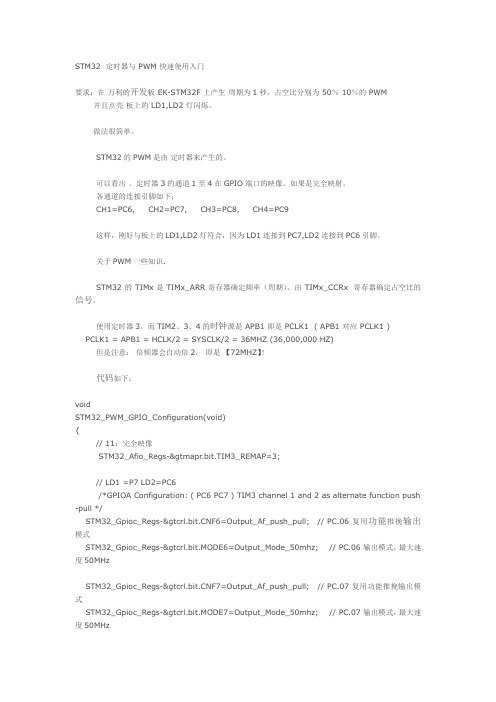
STM32 定时器与 PWM 快速使用入门要求:在万利的开发板 EK-STM32F 上产生周期为1秒,占空比分别为 50% 10%的 PWM 并且点亮板上的 LD1,LD2 灯闪烁。
做法很简单。
STM32的PWM是由定时器来产生的。
可以看出。
定时器3的通道1至4在GPIO端口的映像。
如果是完全映射。
各通道的连接引脚如下:CH1=PC6, CH2=PC7, CH3=PC8, CH4=PC9这样,刚好与板上的LD1,LD2灯符合,因为LD1连接到PC7,LD2连接到PC6引脚。
关于PWM一些知识.STM32的TIMx 是 TIMx_ARR 寄存器确定频率(周期)、由TIMx_CCRx 寄存器确定占空比的信号。
使用定时器3。
而TIM2、3、4的时钟源是 APB1 即是 PCLK1 ( APB1 对应 PCLK1 )PCLK1 = APB1 = HCLK/2 = SYSCLK/2 = 36MHZ (36,000,000 HZ)但是注意:倍频器会自动倍2,即是【72MHZ】!代码如下:voidSTM32_PWM_GPIO_Configuration(void){// 11:完全映像STM32_Afio_Regs->mapr.bit.TIM3_REMAP=3;// LD1 =P7 LD2=PC6/*GPIOA Configuration: ( PC6 PC7 ) TIM3 channel 1 and 2 as alternate function push -pull */STM32_Gpioc_Regs-&F6=Output_Af_push_pull; // PC.06 复用功能推挽输出模式STM32_Gpioc_Regs->crl.bit.MODE6=Output_Mode_50mhz; // PC.06 输出模式,最大速度50MHzSTM32_Gpioc_Regs-&F7=Output_Af_push_pull; // PC.07 复用功能推挽输出模式STM32_Gpioc_Regs->crl.bit.MODE7=Output_Mode_50mhz; // PC.07 输出模式,最大速度50MHz}//end subvoidSTM32_TIM3_Configuration(void){// TIM_DeInit( TIM3);//复位TIM3定时器STM32_Rcc_Regs->apb1rstr.all |= RCC_TIM3RST;STM32_Rcc_Regs->apb1rstr.all &= ~RCC_TIM3RST;//时钟使能STM32_Rcc_Regs->apb1enr.all |=RCC_TIM3EN;/* TIM3 base configuration *///TIM_TimeBaseStructure.TIM_Period = 9999;//TIM_TimeBaseStructure.TIM_Prescaler = 7200;//TIM_TimeBaseStructure.TIM_ClockDivision = 0x0;//TIM_TimeBaseStructure.TIM_CounterMode = TIM_CounterMode_Up;//TIM_TimeBaseInit(TIM3, &TIM_TimeBaseStructure);STM32_Tim3_Regs->arr.all=9999; // 定时周期,PWM频率! 10毫秒*100=1秒STM32_Tim3_Regs->psc.all=720; // 7200分频 72MHZ/72,00 72,000,000/72,00=10,000STM32_Tim3_Regs->cr1.bit.CKD=0; // 时钟分频因子STM32_Tim3_Regs->cr1.bit.DIR=0; // 0:计数器向上计数/* Clear TIM3 update pending flag[清除TIM3溢出中断标志] *///TIM_ClearFlag(TIM3, TIM_FLAG_Update);STM32_Tim3_Regs->sr.bit.UIF=0; //更新中断标记由软件清0 ,例如当上溢或下溢时,软件对CNT重新初始化/* PWM1 Mode configuration: Channel1 Channel2 *///TIM_OCInitStructure.TIM_OCMode = TIM_OCMode_PWM1;//TIM_OCInitStructure.TIM_OutputState = TIM_OutputState_Enable;//TIM_OCInitStructure.TIM_Pulse = CCR1_Val;//TIM_OCInitStructure.TIM_OCPolarity = TIM_OCPolarity_High;//TIM_OC1Init(TIM3, &TIM_OCInitStructure);// timer3 的通道1 是 PC6 引脚, AFIO完全映射STM32_Tim3_Regs-&1P=0; // 输入/捕获1输出极性 0:OC1高电平有效 1:OC1低电平有效STM32_Tim3_Regs-&1E=1; // 输入/捕获1输出使能 1:开启- OC1信号输出到对应的输出引脚。
STM32高级定时器详解
高级定时器(TIM1和TIM8)由一个16位的自动装载计数器组成,它由一个可编程的预分频器驱。
它适合多种用途,包含测量输入信号的脉冲宽度(输入捕获),或者产生输出波形(输出比较、PWM、嵌入死区时间的互补PWM等)。
使用定时器预分频器和RCC时钟控制预分频器,可以实现脉冲宽度和波形周期从几个微秒到几个毫秒的调节。
高级控制定时器和通用定时器是完全独立的,它们不共享任何资源。
它们可以同步操作。
Table 457. TIM寄存器寄存器描述CR1 控制寄存器1CR2 控制寄存器2SMCR 从模式控制寄存器DIER DMA/中断使能寄存器SR 状态寄存器EGR 事件产生寄存器CCMR1 捕获/比较模式寄存器1CCMR2 捕获/比较模式寄存器2CCER 捕获/比较使能寄存器CNT 计数器寄存器PSC 预分频寄存器APR 自动重装载寄存器CCR1 捕获/比较寄存器1CCR2 捕获/比较寄存器2CCR3 捕获/比较寄存器3CCR4 捕获/比较寄存器4DCR DMA控制寄存器DMAR 连续模式的DMA地址寄存器Table 458. 例举了TIM的库函数Table 458. TIM库函数函数名描述TIM_DeInit 将外设TIMx寄存器重设为缺省值TIM_TimeBaseInit根据TIM_TimeBaseInitStruct中指定的参数初始化TIMx的时间基数单位TIM_OCInit 根据TIM_OCInitStruct 中指定的参数初始化外设TIMxTIM_ICInit 根据TIM_ICInitStruct 中指定的参数初始化外设TIMxTIM_TimeBaseStructInit 把TIM_TimeBaseInitStruct 中的每一个参数按缺省值填入TIM_OCStructInit 把TIM_OCInitStruct 中的每一个参数按缺省值填入TIM_ICStructInit 把TIM_ICInitStruct 中的每一个参数按缺省值填入TIM_Cmd 使能或者失能TIMx 外设TIM _ITConfig 使能或者失能指定的TIM 中断TIM_DMAConfig 设置TIMx的DMA接口TIM_DMACmd 使能或者失能指定的TIMx 的DMA请求TIM_InternalClockConfig 设置TIMx 内部时钟TIM_ITRxExternalClockConfig 设置TIMx 内部触发为外部时钟模式TIM_TIxExternalClockConfig 设置TIMx 触发为外部时钟TIM_ETRClockMode1Config 配置TIMx 外部时钟模式1TIM_ETRClockMode2Config 配置TIMx 外部时钟模式2TIM_ETRConfig 配置TIMx 外部触发TIM_SelectInputTrigger 选择TIMx 输入触发源TIM_PrescalerConfig 设置TIMx 预分频TIM_CounterModeConfig 设置TIMx 计数器模式TIM_ForcedOC1Config 置TIMx 输出1 为活动或者非活动电平TIM_ForcedOC2Config 置TIMx 输出2 为活动或者非活动电平TIM_ForcedOC3Config 置TIMx 输出3 为活动或者非活动电平TIM_ForcedOC4Config 置TIMx 输出4 为活动或者非活动电平TIM_ARRPreloadConfig 使能或者失能TIMx在ARR 上的预装载寄存器TIM_SelectCCDMA 选择TIMx 外设的捕获比较DMA源TIM_OC1PreloadConfig 使能或者失能TIMx在CCR1 上的预装载寄存器TIM_OC2PreloadConfig 使能或者失能TIMx在CCR2 上的预装载寄存器TIM_OC3PreloadConfig 使能或者失能TIMx在CCR3 上的预装载寄存器TIM_OC4PreloadConfig 使能或者失能TIMx在CCR4 上的预装载寄存器TIM_OC1FastConfig 设置TIMx 捕获比较1 快速特征。
STM32设置定时器TIM2

STM32如何设置定时器STM32如何设置定时器下面以stm32的TIM2作为实例一步步配置成为定时器:第一种对定时器的基本配置TIM_TimeBaseStructure.TIM_Period = 1000;//设置自动装载寄存器TIM_TimeBaseStructure.TIM_Prescaler = 35999; //分频计数TIM_TimeBaseStructure.TIM_ClockDivision = 0;TIM_TimeBaseStructure.TIM_CounterMode = TIM_CounterMode_Up;//选择向上计数TIM_TimeBaseInit(TIM2, &TIM_TimeBaseStructure);TIM_Cmd(TIM2, ENABLE); //是能定时器始能定时器的中断:TIM_ITConfig(TIM2, TIM_IT_Update, ENABLE);在开启时钟里一定要打开TIM2的时钟,函数表达式如下:RCC_APB1PeriphClockCmd(RCC_APB1Periph_TIM2, ENABLE);4:中断向量函数的编写:void NVIC_Configuration(void){NVIC_InitTypeDef NVIC_InitStructure;#ifdef VECT_TAB_RAM //如果程序在ram中调试那么定义中断向量表在Ram 中否则在Flash中NVIC_SetVectorTable(NVIC_VectTab_RAM, 0x0);#else /* VECT_TAB_FLASH *//* Set the Vector Table base location at 0x08000000 */NVIC_SetVectorTable(NVIC_VectTab_FLASH, 0x0);#endif/* Enable the TIM2 global Interrupt */NVIC_InitStructure.NVIC_IRQChannel = TIM2_IRQChannel;NVIC_InitStructure.NVIC_IRQChannelPreemptionPriority = 0;NVIC_InitStructure.NVIC_IRQChannelSubPriority = 0;NVIC_InitStructure.NVIC_IRQChannelCmd = ENABLE;NVIC_Init(&NVIC_InitStructure);}5:中断函数的编写:当有TIM2的无论哪个中断触发中断发生那么就会进入这个函数TIM2_IRQHandler(void)所以这个更新事件的中断判断要依靠以下语句:if (TIM_GetITStatus(TIM2, TIM_IT_Update) == SET)按照以上步骤配置可以顺利进行定时器的基本定时应用第二种方法:/* Enable TIM2 Update interrupt [TIM2溢出中断允许]*/ TIM_ITConfig(TIM2, TIM_IT_CC1, ENABLE);中断中的设置为:if (TIM_GetITStatus(TIM2, TIM_IT_CC1) != RESET)。
STM32定时器定时时间配置总结
STM32定时器定时时间配置总结STM32系列微控制器内置了多个定时器模块,它们可以用于各种定时功能,如延时、周期性触发、脉冲计数等。
在使用STM32定时器之前,我们需要进行定时时间配置,本文将总结一下STM32定时器定时时间配置的相关知识,包括定时器工作模式、定时器时钟源选择、定时器时钟分频、定时器计数器重载值以及定时器中断配置等内容。
首先,我们需要选择定时器的工作模式。
STM32定时器支持多种工作模式,包括基本定时器模式、高级定时器模式、输入捕获模式和输出比较模式等。
基本定时器模式适用于简单的定时和延时操作,输入捕获模式适用于捕获外部事件的时间参数,输出比较模式适用于产生精确的PWM波形。
根据具体的应用需求,选择合适的工作模式。
其次,我们需要选择定时器的时钟源。
STM32定时器的时钟源可以选择内部时钟源(如系统时钟、HCLK等)或外部时钟源(如外部晶体)。
内部时钟源的稳定性较差,适用于简单的定时操作,而外部时钟源的稳定性较好,适用于要求较高的定时操作。
然后,我们需要选择定时器的时钟分频系数。
定时器的时钟分频系数决定了定时器的时钟频率,从而影响了定时器的计数速度。
我们可以通过改变时钟分频系数来调整定时器的计数速度,从而实现不同的定时时间。
时钟分频系数的选择需要考虑定时器的最大计数周期和所需的定时精度。
接着,我们需要配置定时器的计数器重载值。
定时器的计数器从0开始计数,当计数器达到重载值时,定时器将重新开始计数。
通过改变计数器重载值,可以实现不同的定时时间。
计数器重载值的选择需要考虑定时器的时钟频率和所需的定时时间。
最后,我们需要配置定时器的中断。
定时器中断可以在定时器计数达到重载值时触发,用于通知CPU定时器已经计数完成。
在定时器中断中,我们可以执行相应的中断服务程序,比如改变一些IO口的状态,实现定时操作。
通过配置定时器的中断使能和中断优先级,可以实现不同的中断操作。
需要注意的是,不同型号的STM32微控制器的定时器模块可能略有不同,具体的配置方法和寄存器设置也可能不同,请参考相应的数据手册和参考手册进行具体操作。
STM32HAL库学习系列第4篇定时器TIM-----开始定时器与PWM输出配置
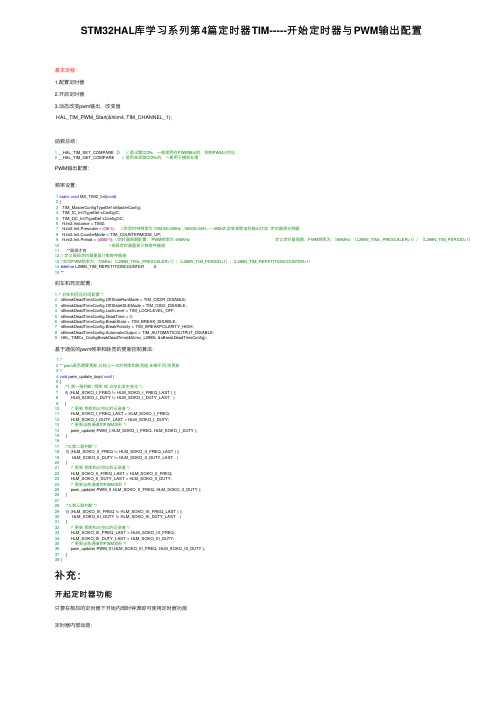
STM32HAL库学习系列第4篇定时器TIM-----开始定时器与PWM输出配置基本流程:1.配置定时器2.开启定时器3.动态改变pwm输出,改变值HAL_TIM_PWM_Start(&htim4, TIM_CHANNEL_1);函数总结:1 __HAL_TIM_SET_COMPARE()// 是设置CCRx,⼀般是⽤在PWM输出的,控制PWM占空⽐2 __HAL_TIM_GET_COMPARE // 是⽤来读取CCRx的,⼀般⽤于捕获处理PWM输出配置:频率设置:1static void MX_TIM2_Init(void)2 {3 TIM_MasterConfigTypeDef sMasterConfig;4 TIM_IC_InitTypeDef sConfigIC;5 TIM_OC_InitTypeDef sConfigOC;6 htim2.Instance = TIM2;7 htim2.Init.Prescaler = (36-1); //实际时钟频率为 72M/36=2MHz /40000=50H,-----490HZ,改变观察电机输出状态定时器预分频器8 htim2.Init.CounterMode = TIM_COUNTERMODE_UP;9 htim2.Init.Period = (4082-1); //定时器周期配置 PWM频率为 490KHz 定义定时器周期,PWM频率为:168MHz/ (L298N_TIMx_PRESCALER+1)/ (L298N_TIM_PERIOD+1)10//⾼级定时器重复计数寄存器值11 **⾼级才有12// 定义⾼级定时器重复计数寄存器值13//实际PWM频率为:72MHz/(L298N_TIMx_PRESCALER+1)/(L298N_TIM_PERIOD+1)/(L298N_TIM_REPETITIONCOUNTER+1)14#define L298N_TIM_REPETITIONCOUNTER 015 **刹车和死区配置:1/* 刹车和死区时间配置 */2 sBreakDeadTimeConfig.OffStateRunMode = TIM_OSSR_DISABLE;3 sBreakDeadTimeConfig.OffStateIDLEMode = TIM_OSSI_DISABLE;4 sBreakDeadTimeConfig.LockLevel = TIM_LOCKLEVEL_OFF;5 sBreakDeadTimeConfig.DeadTime = 0;6 sBreakDeadTimeConfig.BreakState = TIM_BREAK_DISABLE;7 sBreakDeadTimeConfig.BreakPolarity = TIM_BREAKPOLARITY_HIGH;8 sBreakDeadTimeConfig.AutomaticOutput = TIM_AUTOMATICOUTPUT_DISABLE;9 HAL_TIMEx_ConfigBreakDeadTime(&htimx_L298N, &sBreakDeadTimeConfig);基于通信的pwm频率和脉宽的更新控制算法:1/*2** pwm是否需要更新,⽐较上⼀次的频率和脉宽值,如果不同,则更新3*/4void pwm_update_loop( void )5 {6/*1,第⼀路判断: 频率或占空⽐发⽣变化 */7if( (HLM_SOKO_I_FREQ != HLM_SOKO_I_FREQ_LAST ) ||8 HLM_SOKO_I_DUTY != HLM_SOKO_I_DUTY_LAST )9 {10/* 更新频率和占空⽐的记录值 */11 HLM_SOKO_I_FREQ_LAST = HLM_SOKO_I_FREQ;12 HLM_SOKO_I_DUTY_LAST = HLM_SOKO_I_DUTY;13/* 更新当前通道的PWM波形 */14 pwm_update( PWM_I,HLM_SOKO_I_FREQ, HLM_SOKO_I_DUTY );15 }1617/*2,第⼆路判断 */18if( (HLM_SOKO_II_FREQ != HLM_SOKO_II_FREQ_LAST ) ||19 HLM_SOKO_II_DUTY != HLM_SOKO_II_DUTY_LAST )20 {21/* 更新频率和占空⽐的记录值 */22 HLM_SOKO_II_FREQ_LAST = HLM_SOKO_II_FREQ;23 HLM_SOKO_II_DUTY_LAST = HLM_SOKO_II_DUTY;24/* 更新当前通道的PWM波形 */25 pwm_update( PWM_II,HLM_SOKO_II_FREQ, HLM_SOKO_II_DUTY );26 }2728/*3,第三路判断 */29if( (HLM_SOKO_III_FREQ != HLM_SOKO_III_FREQ_LAST ) ||30 HLM_SOKO_III_DUTY != HLM_SOKO_III_DUTY_LAST )31 {32/* 更新频率和占空⽐的记录值 */33 HLM_SOKO_III_FREQ_LAST = HLM_SOKO_III_FREQ;34 HLM_SOKO_III_DUTY_LAST = HLM_SOKO_III_DUTY;35/* 更新当前通道的PWM波形 */36 pwm_update( PWM_III,HLM_SOKO_III_FREQ, HLM_SOKO_III_DUTY );37 }38 }补充:开起定时器功能只要在相应的定时器下开始内部时钟源即可使⽤定时器功能定时器内部动能:定时器时钟配置:M是10的6次⽅微秒是10的-6次⽅内部时钟设置为不分频(CKD),则CK_PSC的时钟频率等于APB1的时钟频率108MHz,即108000 000Hz。
第六章STM32 定时器的使用
}
}
步骤五:配置main函数,实现定时器控制跑马灯。
volatile u32 time;
int i=0;
int main(void) { SystemInit(); //配置系统时钟为72控制跑马灯(P190)
1.理解STM32通用定时器的结构和基本工作原理; 2.掌握STM32通用定时器初始化和操作方法; 3.理解中断概念; 4.掌握STM3中断服务程序的写法。
硬件设计 硬件连接图如下,实验板上stm32f103x处理器
通过配置GPIO实现如下功能:D3~D6轮流点亮,点亮时 间持续1秒。
软件设计 步骤一:添加库函数,以及操作函数。 添加相应库函数:
操作函数有:USER/main.c ;stm32f10x_it.c ;led.h; led.c ;timer.h;timer.c;TIM2_IRQHandler()。 步骤二:在timer.h函数中设置宏定义和函数声明:
void TIM2_NVIC_Config(void); void TIM2_Config(void);
TIN_TimBaseInitTypeDef TIM_TimeBaseStructure;
TIM_TimeBaseStructure.TIM_Period = (10000 - 1); //自动重装的计数值
TIM_TimeBaseStructure.TIM_Prescaler =7200-1 ; // 预分频系数
立即加载计数器(ARPE=0)
更新事件时加载计数器(ARPE=0)
6.2.2 计数器模式 1. 向上计数模式:计数器从0计数到设定的数值,然 后重新从0开始计数并且产生一个计数器溢出事件。
计数器时序图(内部时钟分频因子为1)
STM32通用定时器
STM32的定时器功能很强大,学习起来也很费劲儿.其实手册讲的还是挺全面的,只是无奈TIMER的功能太复杂,所以显得手册很难懂,我就是通过这样看手册:while(!SUCCESS){看手册…}才搞明白的!所以接下来我以手册的顺序为主线,增加一些自己的理解,并通过11个例程对TIMER做个剖析。
实验环境是STM103V100的实验板,MDK3.2 +Library2.东西都不怎么新,凑合用……TIMER主要是由三部分组成:1、时基单元。
2、输入捕获。
3、输出比较。
还有两种模式控制功能:从模式控制和主模式控制。
一、框图让我们看下手册,一开始是定时器的框图,这里面几乎包含了所有定时器的信息,您要是能看明白,那么接下来就不用再看别的了…为了方便的看图,我对里面出现的名词和符号做个注解:TIMx_ETR:TIMER外部触发引脚 ETR:外部触发输入ETRP:分频后的外部触发输入 ETRF:滤波后的外部触发输入ITRx:内部触发x(由另外的定时器触发)TI1F_ED:TI1的边沿检测器。
TI1FP1/2:滤波后定时器1/2的输入TRGI:触发输入 TRGO:触发输出CK_PSC:应该叫分频器时钟输入CK_CNT:定时器时钟。
(定时周期的计算就靠它)TIMx_CHx:TIMER的输入脚 TIx:应该叫做定时器输入信号xICx:输入比较x ICxPS:分频后的ICxOCx:输出捕获x OCxREF:输出参考信号关于框图还有以下几点要注意:1、影子寄存器。
有阴影的寄存器,表示在物理上这个寄存器对应2个寄存器,一个是程序员可以写入或读出的寄存器,称为preload register(预装载寄存器),另一个是程序员看不见的、但在操作中真正起作用的寄存器,称为shadow register(影子寄存器);(详细请参考版主博客/STM32/401461/message.aspx)2、输入滤波机制在ETR何TIx输入端有个输入滤波器,它的作用是以采样频率Fdts来采样N次进行滤波的。
STM32Cubemx配置定时器定时1mS
STM32Cubemx配置定时器定时1mS 最近才发现原来我把定时器⾥的配置参数代表的意义给搞混了,这⾥记录⼀下,防⽌以后⾃⼰忘记。
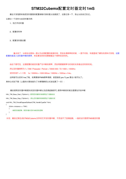
以建⽴⼀个定时1mS定时器为例: 1、先打开定时器 2、配置好时钟 3、配置定时器设置 重点来了,以前在这⾥我⼀直以为这⾥配置的就是时间,然后在调频率的时候,⼀直不对劲,知道查阅了硬⽯的资料才发现,这⾥配置的是进⼊定时器中断的频率,然后要定的时间要跟据这个频率来定时的。
由这个图可见,这⾥配置的是定时器产⽣中断的频率,然后再跟据频率与时间的关系推出定时的时间。
所以定时器频率为 f = 72M / Prescaler / Period = 72000 000 / 72 /1000 = 1000Hz; 定时时间T = 1 / f 则: 1s / 1000Hz = 1000 000us / 1000Hz = 1000us =1ms。
这样就可以定时1ms了啦,如果要做PWM频率调频,就直接改 pre 与 per 算出 f 就可以了。
具体公式如下图(上⾯的计算我是为了⽅便理解把公式逆运算了⼀次): 最后使⽤定时器中断跟关闭定时器中断以及回调函数即可, 使⽤中断的时候注意要先开启中断HAL_TIM_Base_Start_IT(&htim1); //使⽤定时器的时候调⽤这个函数启动HAL_TIM_Base_Stop_IT(&htim1); //停⽌定时器的时候调⽤这个函数关闭void HAL_TIM_PeriodElapsedCallback(TIM_HandleTypeDef *htim){ if(htim->Instance == TIM1) { //编写回调逻辑,即定时器1定时1MS后的逻辑 }}补充:最后记得⽣成STM32Cubemx⽂件时打开定时器中断,不然进不了回调函数,⼀般的话习惯⽤TIM3做定时器。
STM32定时器
一、定时器(TIMx)1.关联函数:A.TIM_OC1Init(TIM_TypeDef* TIMx, TIM_OCInitTypeDef* TIM_OCInitStruct) :TIMx通道1配置函数。
B.TIM_OC2Init(TIM_TypeDef* TIMx, TIM_OCInitTypeDef* TIM_OCInitStruct) :TIMx通道2配置函数。
C.TIM_OC3Init(TIM_TypeDef* TIMx, TIM_OCInitTypeDef* TIM_OCInitStruct):TIMx通道3配置函数。
D.TIM_OC4Init(TIM_TypeDef* TIMx, TIM_OCInitTypeDef* TIM_OCInitStruct):TIMx通道4配置函数。
E.TIM_ICInit(TIM_TypeDef* TIMx, TIM_ICInitTypeDef* TIM_ICInitStruct):TIMx捕获输入配置函数F.TI1_Config(TIM_TypeDef* TIMx, uint16_t TIM_ICPolarity, uint16_t TIM_ICSelection,uint16_t TIM_ICFilter):TI1配置函数G.TI2_Config(TIM_TypeDef* TIMx, uint16_t TIM_ICPolarity, uint16_t TIM_ICSelection,uint16_t TIM_ICFilter):TI2配置函数H.TI3_Config(TIM_TypeDef* TIMx, uint16_t TIM_ICPolarity, uint16_t TIM_ICSelection,uint16_t TIM_ICFilter):TI3配置函数I.TI4_Config(TIM_TypeDef* TIMx, uint16_t TIM_ICPolarity, uint16_t TIM_ICSelection,uint16_t TIM_ICFilter):TI4配置函数J.TIM_SetICxPrescaler(TIM_TypeDef* TIMx, uint16_t TIM_ICPSC):配置TIMx输入捕获x的预分频器函数K.TIM_PWMIConfig(TIM_TypeDef* TIMx, TIM_ICInitTypeDef* TIM_ICInitStruct):TIMx的PWM输入模式配置函数L.TIM_BDTRConfig(TIM_TypeDef* TIMx, TIM_BDTRInitTypeDef *TIM_BDTRInitStruct)配置刹车, 死区时间, 锁定级别, OSSI,OSSR 状态和自动输出函数. M.TIM_Cmd(TIM_TypeDef* TIMx, FunctionalState NewState)typedef enum {DISABLE = 0, ENABLE = !DISABLE} FunctionalState; TIMx功能的开关状态N.TIM_CtrlPWMOutputs(TIM_TypeDef* TIMx, FunctionalState NewState)typedef enum {DISABLE = 0, ENABLE = !DISABLE} FunctionalState; TIMx的PWM功能的开关状态O.TIM_ITConfig(TIM_TypeDef* TIMx, uint16_t TIM_IT, FunctionalState NewState)TIMx中断和DMA开启与关断函数P.TIM_GenerateEvent(TIM_TypeDef* TIMx, uint16_t TIM_EventSource)事件产生配置函数Q.TIM_DMAConfig(TIM_TypeDef* TIMx, uint16_t TIM_DMABase, uint16_tTIM_DMABurstLength)TIMx的DMA基本配置函数R.TIM_DMACmd(TIM_TypeDef* TIMx, uint16_t TIM_DMASource, FunctionalState NewState)TIMx的DMA发送函数【说明:】函数体中,tmpccmrx 、tmpccer 、tmpcr2 为中间变量,先读取当前寄存器的配置数据,再使用&=配置相关位的数值以便保留当前配置数据。
第八章 STM32定时器

RCC_APB1PeriphClockCmd (RCC_APB1Periph_TIM2 ,ENABLE) ; }
8.7 TIM2应用实例概述
2.GPIO的配置
设系统时钟为72MHz ,则定时时间T: T= (TIM_Period+1)* (TIM_Pre scaler+1)/TI MxCLK= (35999+1)* (1999+1)/72MHz= 1s
8.6 通用定时器TIMx寄存器
STM32通用定时器的TIMx寄存器较多 ,有 18个 ,使用较复杂。
8.7 TIM2应用实例概述
3.NVIC的配置
设置初始化中断向量
void NVIC_Config (void)
{
/*设置优先分级组,选择中断通道*/
NVIC_In itTypeDef NVIC_In itStructure ;
NVIC_PriorityGroupConfig (NVIC_PriorityGrou p_0) ;
6) TIM_TimeBase In it ():TIMx初始化 7) TIM_ClearFlag (): 清除溢出中断标志; 8) TIM_ITConfig ():开启定时器中断 ,和NVIC作
用相当于双保险 ;便于以后开启和关闭定时器。
9) TIM_Cmd(): 允许定时器工作。
8.7 TIM2应用实例概述
具体选择哪个时钟可通过TIMx_SMCR寄 存器的相关位来设置 。CK_INT时钟是从APB1 倍频得到的 。从图中可看出 , 定时器的时钟 不是直接来自APB1或APB2 ,而是来自于输入 为APB1或APB2的一个倍频器。
- 1、下载文档前请自行甄别文档内容的完整性,平台不提供额外的编辑、内容补充、找答案等附加服务。
- 2、"仅部分预览"的文档,不可在线预览部分如存在完整性等问题,可反馈申请退款(可完整预览的文档不适用该条件!)。
- 3、如文档侵犯您的权益,请联系客服反馈,我们会尽快为您处理(人工客服工作时间:9:00-18:30)。
February 2012Doc ID 022500 Rev 11/27AN4013Application noteSTM32F1xx, STM32F2xx, STM32F4xx, STM32L1xx timer overview1 IntroductionThis document:●presents an overview of the timer peripherals in the STM32F1xx, STM32F2xx, STM32F4xx and STM32L1xx microcontroller families,●describes the various modes and specific features of the timers, such as clock sources,●explains how to use the available modes and features,●explains how to compute the time base in each configuration,●describes the timer synchronization sequences and the advanced features for motor control applications, in addition to the basic timer modes.For each mode, typical configurations are presented and examples of how to use the modes are provided.In the rest of this document (unless otherwise specified), the term STM32xx is used to refer to STM32F1xx, STM32F2xx, STM32F4xx and STM32L1xx microcontroller families.Contents AN4013Contents1Introduction . . . . . . . . . . . . . . . . . . . . . . . . . . . . . . . . . . . . . . . . . . . . . . . . 1 2Overview . . . . . . . . . . . . . . . . . . . . . . . . . . . . . . . . . . . . . . . . . . . . . . . . . . 33Basic timer modes . . . . . . . . . . . . . . . . . . . . . . . . . . . . . . . . . . . . . . . . . . 63.1Clock input sources . . . . . . . . . . . . . . . . . . . . . . . . . . . . . . . . . . . . . . . . . . 63.1.1Internal clock . . . . . . . . . . . . . . . . . . . . . . . . . . . . . . . . . . . . . . . . . . . . . . 63.1.2External clock . . . . . . . . . . . . . . . . . . . . . . . . . . . . . . . . . . . . . . . . . . . . . 63.2Time base generator . . . . . . . . . . . . . . . . . . . . . . . . . . . . . . . . . . . . . . . . . 73.3Timer input capture mode . . . . . . . . . . . . . . . . . . . . . . . . . . . . . . . . . . . . . 93.4Timer output compare mode . . . . . . . . . . . . . . . . . . . . . . . . . . . . . . . . . . 103.5Timer PWM mode . . . . . . . . . . . . . . . . . . . . . . . . . . . . . . . . . . . . . . . . . . 123.6Timer one pulse mode . . . . . . . . . . . . . . . . . . . . . . . . . . . . . . . . . . . . . . . 134Timer synchronization . . . . . . . . . . . . . . . . . . . . . . . . . . . . . . . . . . . . . . 144.1Timer system link . . . . . . . . . . . . . . . . . . . . . . . . . . . . . . . . . . . . . . . . . . . 144.2Master configuration . . . . . . . . . . . . . . . . . . . . . . . . . . . . . . . . . . . . . . . . . 144.3Slave configuration . . . . . . . . . . . . . . . . . . . . . . . . . . . . . . . . . . . . . . . . . . 155Advanced features for motor control . . . . . . . . . . . . . . . . . . . . . . . . . . 165.1Signal generation . . . . . . . . . . . . . . . . . . . . . . . . . . . . . . . . . . . . . . . . . . . 165.2Specific features for motor control applications . . . . . . . . . . . . . . . . . . . . 185.2.1Complementary signal and dead time feature . . . . . . . . . . . . . . . . . . . . 185.2.2Break input . . . . . . . . . . . . . . . . . . . . . . . . . . . . . . . . . . . . . . . . . . . . . . . 195.2.3Locking mechanism . . . . . . . . . . . . . . . . . . . . . . . . . . . . . . . . . . . . . . . . 205.2.4Specific features for feedback measurement . . . . . . . . . . . . . . . . . . . . . 206Specific applications . . . . . . . . . . . . . . . . . . . . . . . . . . . . . . . . . . . . . . . . 246.1Infrared application . . . . . . . . . . . . . . . . . . . . . . . . . . . . . . . . . . . . . . . . . . 246.23-phase AC and PMSM control motor . . . . . . . . . . . . . . . . . . . . . . . . . . . 246.3Six-step mode . . . . . . . . . . . . . . . . . . . . . . . . . . . . . . . . . . . . . . . . . . . . . 24 7Revision history . . . . . . . . . . . . . . . . . . . . . . . . . . . . . . . . . . . . . . . . . . . 26 2/27Doc ID 022500 Rev 1AN4013OverviewDoc ID 022500 Rev 13/272 OverviewSTM32 devices use various types of timers, with the following features for each:●General purpose timers are used in any application for output compare (timing and delay generation), one-pulse mode, input capture (for external signal frequency measurement), sensor interface (encoder, hall sensor)...●Advanced timers : these timers have the most features. In addition to general purpose functions, they include several features related to motor control and digital power conversion applications: three complementary signals with deadtime insertion, emergency shut-down input.●One or two channel timers : used as general purpose timers with a limited number of channels.●One or two channel timers with complementary output : same as previous type, but having a deadtime generator on one channel. This allows having complementary signals with a time base independent from the advanced timers.●Basic timers have no input/outputs and are used either as timebase timers or for triggering the DAC peripheral.Table 1 summarizes the STM32 family timers.Table 2 presents a general overview of timer features.Overview AN40134/27Doc ID 022500 Rev 1Table 1.STM32 family timersTimer typeSTM32F101/102/ 103/105/107familiesSTM32F100family STM32L1familySTM32F2 and STM32F4families AdvancedTIM1TIM1TIM1TIM8TIM8General purpose16-bitTIM2TIM2TIM2TIM3TIM3TIM3TIM3TIM4TIM4TIM4TIM4TIM5TIM532-bitTIM2TIM5BasicTIM6TIM6TIM6TIM6TIM7TIM7TIM7TIM71-channelTIM10TIM10TIM10TIM11TIM11TIM11TIM13TIM13TIM13TIM14TIM14TIM142-channelTIM9TIM9TIM9TIM12TIM12TIM121-channel with one complementary output TIM152-channel with one complementary outputTIM16TIM17AN4013OverviewDoc ID 022500 Rev 15/27Table 2.Timer features overviewTimer typeCounter resolutionCounter typeDMAChannelsComp. channelsSynchronizationMaster config.Slave config.Advanced 16 bit up, down and center aligned Y es 43Y es Y es General purpose 16 bit 32 bit (1) up, down and center alignedY es 40Y es Y es Basic 16 bit up Y es 00Y es No 1-channel 16 bit up No 10Y es (OC signal) No 2-channel16 bitupNo2Y es Y es1-channel with one complementary output16 bit up Y es 11Y es (OC signal)No2-channel with one complementary output16 bit up Y es 21No Y es1.TIM2 and TIM5 are 32-bit counter resolution in the STM32F2 and STM32F4 families.Basic timer modes AN40136/27Doc ID 022500 Rev 13 Basic timer modesBasic timers can be programmed to work in one of the following configurations.3.1 Clock input sourcesThe timer can be synchronized by several clocks simultaneously:●Internal clock ●External clock –External mode1 (TI1 or TI2 pins)–External clock mode2 (ETR pin)–Internal trigger clock (ITRx)3.1.1 Internal clockThe timer is clocked by default by the internal clock provided from the RCC. To select thisclock source, the SMCR_SMS (if present) bits should be reset.3.1.2 External clockThe external clock timer is divided in two categories:●External clock connected to TI1 or TI2 pins ●External clock connected to ETR pinIn these cases, the clock is provided by an external signal connected to TIx pins or ETR pin.The maximum external clock frequency should be verified.Note:1In addition to all these clock sources, the timer should be clocked with the APBx clock.2The external clocks are not directly feeding the prescaler, but they are first synchronized with the APBx clock through dedicated logical blocks.External clock mode1 (TI1 or TI2 pins)In this mode the external clock will be applied on timer input TI1 pin or TI2 pin. To do this:1.Configure the timers to use the TIx pin as input:a) Select the pin to be used by writing CCxS bits in the TIMx_CCMR1 register.b) Select the polarity of the input:For the STM32F10x family : by writing CCxP in the TIMx_CCER register to select the rising or the falling edge;For the STM32L1x, STM32F2xx or STM32F4xx: by writing CCxP and CCxNP in the TIMx_CCER register to select the rising/falling edge, or both edges (a).a.For the STM32F10x family, polarity selection for both edges can be achieved by using TI1F_ED, but only for TI1 input.AN4013Basic timer modesc) Configure the filter and the prescaler if needed by writing the ICxF[3:0] bits in theTIMx_CCMR1:Select the timer TIx as the trigger input source by writing TS bits in theTIMx_SMCR register.Select the external clock mode1 by writing SMS=111 in the TIMx_SMCR register.Enable the corresponding channel by setting the CCEx bit in the TIMx_CCERregister.2. Select the timer TIx as the trigger input source by writing TS bits in the TIMx_SMCRregister.3. Select the external clock mode1 by writing SMS=111 in the TIMx_SMCR register.External clock mode2 (ETR pin)The external clock mode2 uses the ETR pin as timer input clock. To use this feature:1.Select the external clock mode2 by writing ECE = 1 in the TIMx_SMCR register.2. Configure, if needed, the prescaler, the filter and the polarity by writing ETPS [1:0], ETF[3:0] and ETP in the TIMx_SMCR register.Internal trigger clock (ITRx)This is a particular mode of timer synchronization. When using one timer as a prescaler foranother timer, the first timer update event or output compare signal is used as a clock for thesecond one.3.2 Time base generatorThe timer can be used as a time base generator. Depending on the clock, prescaler andautoreload, repetition counter (if present) parameters, the 16-bit timer can generate anupdate event from a nanosecond to a few minutes. For the 32-bit timer, the range is larger.Example update event periodThe update event period is calculated as follows:Update_event = TIM_CLK/((PSC + 1)*(ARR + 1)*(RCR + 1))Where:TIM_CLK = timer clock inputPSC = 16-bit prescaler registerARR = 16/32-bit Autoreload registerRCR = 16-bit repetition counterTIM_CLK = 72 MHzPrescaler = 1Auto reload = 65535No repetition counter RCR = 0Update_event = 72*106/((1 + 1)*(65535 + 1)*(1))Update_event = 549.3 HzDoc ID 022500 Rev 17/27Basic timer modes AN40138/27Doc ID 022500 Rev 1Example external clock mode2In this mode, the update event period is calculated as follows:Update_event = ETR_CLK/((ETR_PSC)*(PSC + 1)*(ARR + 1)*(RCR + 1))Where ETR_CLK = the external clock frequency connected to ETR pin.ETR_CLK = 100 kHz Prescaler = 1ETR_PSC = 2Autoreload = 255Repetition counter = 2Update_event= 100*103/((2 + 1)* (1+ 1)*((255 + 1)*(2 + 1))Update_event = 21.7 HzExample external clock mode1In this mode, the update event period is calculated as follows:Update_event = TIx_CLK/((PSC + 1)*(ARR + 1)*(RCR +1))Where TIx_CLK = the external clock frequency connected to TI1 pin or TI2 pin.TIx_CLK = 50 kHz Prescaler = 1Auto reload = 255Repetition counter = 2Update_event = 50 000/((1+ 1)*((255 + 1)*(2 + 1))Update_event = 32.55 HzExample Internal trigger clock (ITRx) mode1In this mode, the update event period is calculated as follows:Update_event = ITRx_CLK/((PSC + 1)*(ARR + 1)*(RCR + 1))Where ITRx_CLK = the internal trigger frequency mapped to timer trigger input (TRGI)ITRx_CLK = 8 kHz Prescaler = 1Auto reload = 255Repetition counter = 1Update_event = 8000/((1+ 1)*((255 + 1)*(1 + 1))Update_event = 7.8 HzDepending on the counter mode, the update event is generated each:●Overflow, if up counting mode is used: the DIR bit is reset in TIMx_CR1 register ●Underflow, if down counting mode is used: the DIR bit is set in TIMx_CR1 register ●Overflow and underflow, if center aligned mode is used: the CMS bits are different from zero.AN4013Basic timer modesDoc ID 022500 Rev 19/27The update event is generated also by:●Software, if the UG (update generation) bit is set in TIM_EGR register.●Update generation through the slave mode controllerAs the buffered registers (ARR, PSC, CCRx) need an update event to be loaded with their preload values, set the URS (Update Request Source) to 1 to avoid the update flag each time these values are loaded. In this case, the update event is only generated if the counter overflow/underflow occurs.The update event can be also disabled by setting the bit UDIS (update disable) in the CR1 register. In this case, the update event is not generated, and shadow registers (ARR, PSC, CCRx) keep their value. The counter and the prescaler are reinitialized if the UG bit is set, or if a hardware reset is received from the slave mode controller.An interrupt or/ and a DMA request can be generated when the UIE bit or/and UDE bit are set in the DIER register.For more details on using the timer in this mode, refer to the examples provided in the STM32xx standard peripheral libraries in the /Project/STM32xx_StdPeriph_Examples/ TIM/TimeBase folder.3.3 Timer input capture modeThe timer can be used in input capture mode to measure an external signal. Depending on timer clock, prescaler and timer resolution, the maximum measured period is deduced.To use the timer in this mode:1.Select the active input by setting the CCxS bits in CCMRx register. These bits should be different from zero, otherwise the CCRx register will be read only.2. Program the filter by writing the IC1F[3:0] bits in the CCMRx register, and the prescaler by writing the IC1PSC[1:0] if needed.3.Program the polarity by writing the CCxNP/CCxP bits to select between rising, falling or both edges.The input capture module is used to capture the value of the counter after a transition is detected by the corresponding input channel. To get the external signal period, twoconsecutive captures are needed. The period is calculated by subtracting these two values.Period = Capture(1) /(TIMx_CLK *(PSC+1)*(ICxPSC)*polarity_index(2))The capture difference between two consecutive captures CCRx_tn and CCRx_tn+1:●If CCRx_tn < CCRx_tn+1: capture = CCRx_tn+1 - CCRx_tn●If CCRx_tn > CCRx_tn+1: capture = (ARR_max - CCRx_tn) + CCRx_tn+1The polarity index is 1 if the rising or falling edge is used, and 2 if both edges are used.Particular caseTo facilitate the input capture measurement, the timer counter is reset after each rising edge detected on the timer input channel by:●selecting TIxFPx as the input trigger by setting the TS bits in the SMCR register ●selecting the reset mode as the slave mode by configuring the SMS bits in the SMCR registerBasic timer modes AN401310/27Doc ID 022500 Rev 1Using this configuration, when an edge is detected, the counter is reset and the period of the external signal is automatically given by the value on the CCRx register. This method is used only with channel 1 or channel 2.In this case, the input capture prescaler (ICPSC) is not considered in the period computation.The period is computed as follows:Period = CCRx /(TIMx_CLK *(PSC+1)* polarity_index(1))The polarity index is 1 if rising or falling edge is used, and 2 if both edges are used.For more details on using the timer in this mode, refer to the examples provided in the STM32xx standard peripheral libraries in the /Project/STM32xx_StdPeriph_Examples/ TIM/InputCapture folder.3.4 Timer output compare modeTo control an output waveform, or to indicate when a period of time has elapsed, the timer is used in one of the following output compare modes. The main difference between these modes is the output signal waveform.●Output compare timing : The comparison between the output compare register CCRx and the counter CNT has no effect on the outputs. This mode is used to generate a timing base.●Output compare active : Set the channel output to active level on match. The OCxRef signal is forced high when the counter (CNT) matches the capture/compare register (CCRx).●Output compare inactive : Set channel to inactive level on match. The OCxRef signal is forced low when the counter (CNT) matches the capture/compare register (CCRx).●Output compare toggle : OCxRef toggles when the counter (CNT) matches the capture/compare register (CCRx).●Output compare forced active/inactive : OCREF is forced high (active mode) or low (inactive mode) independently from counter value.AN4013Basic timer modesTo configure the timer in one of these modes:1.Select the clock source.2. Write the desired data in the ARR and CCRx registers.3. Configure the output mode:a) Select the output compare mode: timing / active / inactive / toggle.b) In case of active, inactive and toggle modes, select the polarity by writing CCxP inCCER register.c) Disable the preload feature for CCx by writing OCxPE in CCMRx register.d) Enable the capture / compare output by writing CCxE in CCMRx register.4. Enable the counter by setting the CEN bit in the TIMx_CR1 register.5. Set the CCxIE / CCxDE bit if an interrupt / DMA request is to be generated.Timer output compare timing / toggle update rate computationCCx update rate = TIMx_Counter_CLK / CCRx●If internal clock: TIMx_Counter_CLK = TIM_CLK / (PSC + 1)●If external clock mode2: TIMx_Counter_CLK = ETR_CLK / ((ETR_PSC)*(PSC + 1))●If external clock mode1: TIMx_Counter_CLK = ETR_CLK / ((ETR_PSC)*(PSC + 1))Timer output compare active/inactive delay computationCCx_delay = CCRx /TIMx_Counter_CLK●If internal clock: TIMx_Counter_CLK = TIM_CLK / (PSC + 1)●If external clock mode2: TIMx_Counter_CLK = ETR_CLK / ((ETR_PSC)*(PSC + 1))●If external clock mode1: TIMx_Counter_CLK = ETR_CLK / ((ETR_PSC)*(PSC + 1))●If internal trigger clock: TIMx_Counter_CLK = ITRx_CLK / (PSC + 1)For more details on using the timer in this mode, refer to the examples provided in theSTM32xx standard peripheral libraries, in the /Project/STM32xx_StdPeriph_Examples/TIM/OC_Toggle, /OCActive and /OCInactive folders.Doc ID 022500 Rev 111/27Basic timer modes AN401312/27Doc ID 022500 Rev 13.5 Timer PWM modeThe timer is able to generate PWM in edge-aligned mode or center-aligned modeindependently on each channel, with a frequency determined by the value of the TIMx_ARR register, and a duty cycle determined by the value of the TIMx_CCRx register.PWM mode 1●In up-counting, channelx is active as long as CNT< CCRx, otherwise it is inactive. ●In down-counting, channelx is inactive as long as CNT> CCRx, otherwise it is active PWM mode 1.●In up-counting, channelx is inactive as long as CNT < CCRx, otherwise it is active. ●In down-counting, channelx is active as long as CNT > CCRx, otherwise it is inactive.Note:Active when OCREF = 1, inactive when OCREF = 0.To configure the timer in this mode:1.Configure the output pin:a) Select the output mode by writing CCS bits in CCMRx register.b) Select the polarity by writing the CCxP bit in CCER register.2. Select the PWM mode (PWM1 or PMW2) by writing OCxM bits in CCMRx register.3. Program the period and the duty cycle respectively in ARR and CCRx registers.4. Set the preload bit in CCMRx register and the ARPE bit in the CR1 register.5.Select the counting mode:a) PWM edge-aligned mode: the counter must be configured up-counting or down-counting.b) PWM center aligned mode: the counter mode must be center aligned countingmode (CMS bits different from '00').6. Enable the capture compare.7.Enable the counter.For more details on using the timer in this mode, refer to the examples provided in the STM32xx standard peripheral libraries, in the /Project/STM32xx_StdPeriph_Examples/ TIM/PWM_Output and /7PWM_Output folders.AN4013Basic timer modes3.6 Timer one pulse modeOne pulse mode (OPM) is a particular case of the input capture mode and the outputcompare mode. It allows the counter to be started in response to a stimulus and to generatea pulse with a programmable length after a programmable delay.To configure the timer this mode:1.Configure the input pin and mode:a) Select the TIxFPx trigger to be used by writing CCxS bits in CCMRx register.b) Select the polarity of the input pin by writing CCxP and CCxNP bits in CCERregister.c) Configure the TIxFPx trigger for the slave mode trigger by writing TS bits in SMCRregister.d) Select the trigger mode for the slave mode by writing SMS = 110 in SMCRregister.2. Configure the output pin and mode:a) Select the output polarity by writing CCyP bit in CCER register.b) Select the output compare mode by writing OCyM bits in CCMRy register (PWM1or PWM2 mode).c) Set the delay value by writing in CCRy register.d) Set the autoreload value to have the desired pulse: pulse = TIMy_ARR -TIMy_CCRy.3. Select the one pulse mode by setting the OPM bit in CR1 register, if only one pulse is tobe generated. Otherwise this bit should be reset.Delay = CCRy/(TIMx_CLK/(PSC + 1))Pulse-Length = (ARR - CCRy)/(TIMx_CLK/(PSC + 1))For more details on using the timer in this mode, refer to the examples provided in theSTM32xx standard peripheral libraries, in the /Project/STM32xx_StdPeriph_Examples/TIM/OnePulse folder.Doc ID 022500 Rev 113/27Timer synchronization AN401314/27Doc ID 022500 Rev 14 Timer synchronization4.1Timer system linkSTM32 timers are linked together internally for timer synchronization or chaining. Each timerhas several internal trigger inputs and outputs. These signals allow the timer to be connected with other timers.4.2 Master configurationWhen a timer is selected as a master timer, the corresponding trigger output signal is usedby the slave internal trigger (when configured). The trigger output can be selected from the following list:●Reset : the UG bit from the EGR register is used as a trigger output (TRGO).●Enable : the counter enable signal is used as a trigger output (TRGO). It is used to start several timers at the same time, or to control a window in which a slave timer is enabled.●Update : the update event is selected as trigger output (TRGO). For example, a master timer can be used as a prescaler for a slave timer.●Compare pulse : the trigger output sends a positive pulse when the CC1IF flag is to be set (even if it was already high) as soon as a capture or a compare match occurs.●OC1Ref : OC1REF signal is used as trigger output (TRGO).●OC2Ref : OC2REF signal is used as trigger output (TRGO).●OC3Ref : OC3REF signal is used as trigger output (TRGO).●OC4Ref : OC4REF signal is used as trigger output (TRGO).AN4013Timer synchronizationDoc ID 022500 Rev 115/27To configure a timer in master mode:1.Configure your timer.2. Select the trigger output to be used, by writing the MSM (Master Mode Selection) bits in CR2 register.3.Enable the MSM (Master/slave mode) bit in the SMCR register to allow a perfect synchronization between the current timer and its slaves (through TRGO).4.3 Slave configurationThe slave timer is connected to the master timer through the input trigger. Each ITRx isconnected internally to another timer, and this connection is specific for each STM32 product.The slave mode can be:●Reset mode : rising edge of the selected trigger input (TRGI) reinitializes the counter and generates an update of the registers.●Gated mode : the counter clock is enabled when the trigger input (TRGI) is high. The counter stops (but is not reset) as soon as the trigger becomes low. Both start and stop of the counter are controlled.●Trigger mode : the counter starts at a rising edge of the trigger TRGI (but it is not reset). Only the start of the counter is controlled.●External clock mode 1: rising edges of the selected trigger (TRGI) clock the counter.To configure a timer in slave mode:1.Select the slave mode to be used by writing SMS (Slave Mode Selection) bits in SMCR register.2.Select the internal trigger to be used by writing TS (T rigger selection) bits in SMCR registerFor more details on using the timer in this mode, refer to the examples provided in the STM32xx standard peripheral libraries, in the /Project/STM32xx_StdPeriph_Examples/ TIM/Cascade_Synchro, /ExtTrigger_Synchro and /Parallel_Synchro folders.5 Advanced features for motor controlgeneration5.1 SignalThe STM32 timer can output two complementary signals and manage the switching-off andthe switching-on instants of the outputs.The complementary signals OCx and OCxN are activated by a combination of severalcontrol bits: the CCxE and CCxNE and the MOE, OISx, OISxN, OSSI and OSSR bits.The main output enable (MOE) bit is reset as soon as a break input is active. It is set bysoftware or automatically, depending on the automatic output enable (AOE) bit. When thisbit (MOE) is reset, the OCx and OCxN outputs are disabled or forced to idle state (OISxOISxN), depending on whether the OSSI bit is set or not.Note:The MOE bit is valid only on the channels that are configured in output.The Off-state selection for Run mode (OSSR) bit is used when MOE=1 on channels thathave a complementary output configured as outputs. When this bit is set, OCx and OCxNoutputs are enabled with their inactive level as soon as CCxE=1 or CCxNE=1. The output isstill controlled by the timer.The Off-state selection for Idle mode (OSSI) bit is used when MOE=0 due to a break eventor by a software write, on channels configured as outputs. When this bit is set, OCx andOCxN outputs are first forced with their inactive level, then forced to their idle level after thedead time. The timer maintains its control over the output.Table3 explains the possible configurations of the advanced timer.16/27Doc ID 022500 Rev 1Doc ID 022500 Rev 117/27Note:1Dead time insertion is enabled by setting both CCxE and CCxNE bits, and the MOE bit.2When only OCxN is enabled (CCxE=0, CCxNE=1), it is not complemented and becomes active as soon as OCxREF is high. For example, if CCxNP=0 then OCxN=OCxRef. On the other hand, when both OCx and OCxN are enabled (CCxE=CCxNE=1) OCx becomes active when OCxREF is high, whereas OCxN is complemented and becomes active when OCxREF is low.Table 3.Advanced timer configurationsControl bitsOutput stateTypical useMOEOSSI OSSR OCxE OCxNE OCx outputstate OCxN outputstate 1x 000Output disable Output disable General purpose x 001Output disable OCxREF + Polarity x1OCxREF + Polarity Output disable x 011OCxREF + Polarity + Deadtime (not OCxREF)+ Polarity + Deadtime Motor control (sinewave)x 100Output disabledOutput disabled Motor control (6-steps)x 101Off-state OCxREF + Polarity x11OCxREF + Polarity Off-state x 111OCxREF + Polarity + Deadtime (not OCxREF)+ Polarity + Deadtime Motor control (sinewave)MOE OSSI OSSR OCxE OCxNE OCx outputstateOCxN outputstateComments 00x 00Output disableOutputs disconnected from I/O ports0x 010x 100x 111x 00Off-state(outputs are first forced with their inactive level then forced to their idle level after the deadtime.)All PWMs OFF (low Z for safe stop)1x 011x 101x1118/27Doc ID 022500 Rev 15.2 Specific features for motor control applications5.2.1 Complementary signal and dead time featureSTM32 advanced timers can generate up to three complementary outputs with insertion ofdead time.To use the complementary signal for one channel, set the two output compare enable bits of this channel and its complementary (OCxE and OCxNE) channel.If the dead time bits are different from zero, the two signals are generated with insertion of a dead time as illustrated in Figure 2: Two signals are generated with insertion of a dead time :The dead time parameter is computed using the DTG[7:0] bits and the dead time clock (Tdtg).The dead time clock is computed as follows:Tdtg = TDTS, if DTG[7] = 0Tdtg = 2 x TDTS, if DTG[6] = 0Tdtg = 8 x TDTS, if DTG[5] = 0Tdtg = 16 x TDTS, if DTG[7:5] = 111Note:TCK_INT is the timer internal clock.Where:TDTS = TCK_INT, if CKD[1:0] = 00TDTS = 2 x TCK_INT, if CKD[1:0] = 01TDTS = 4 x TCK_INT, if CKD[1:0] = 10。
