继电器规格书
继电器规格书 - RJ-SS-112DM1-S - WRG-Wangrong说明书
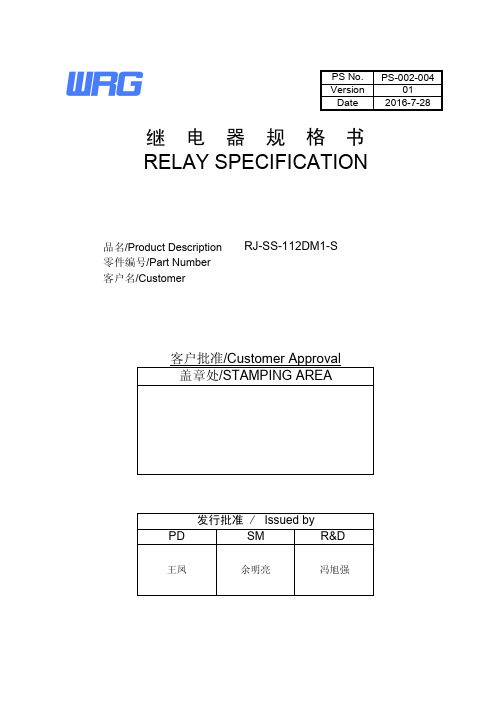
PS-002-004012016-7-28客户名/CustomerRELAY SPECIFICATION零件编号/Part Number品名/Product Description RJ-SS-112DM1-SDate Version PS No.继 电 器 规 格 书冯旭强余明亮王凤客户批准/Customer Approval 盖章处/STAMPING AREAR&DSM PD发行批准 / Issued by序号担当00凌剑冰01凌剑冰2016-7-28增加黄山工厂描述变更履历/HISTORY日期变更项目2015-4-13初版1零件清单/PARTS LIST123 4 5 6 7 8 9 10 11 12 13 14 15 16Ver01RG3015010GN6-30 M8XRG301RG301FLAME CLASSUL FILE No.E171666E53664E171666E171666TYPE/TREATMENT型号/处理方式镀镍Vicryst R850Part零件名No.材质MATERIAL镀镍Nickel Plated镀镍Nickel PlatedNickel Plated3UEW 155(F Class)镀锡Base基座骨架Bobbin外壳Case推片CardSolder Coated挂钩Hinge可动弹片C Terminal轭铁Yoke衔铁Armature线材Wire可动接点C ContactM接点M ContactE171666线圈端子Coil Terminal铁芯CoreM端子M TerminalE234867PS-002-004E164502Epoxy胶水UV GlueSealing ResinAg Alloy铜包钢Cu coverd Steel聚氨脂漆包圆铜线Cu Alloy铜合金Polyurethane copper wire环氧树脂Steel铜合金Cu Alloy银合金Ag Alloy银合金Cu Alloy铁LCP铁Steel铁Steel铜合金PBTUV胶PBTPBT2.性能/SPECIFICATIONS2.1驱动部分/COIL SPECIFICATIONS2.1.1额定电压12VDC(在20℃时)Rated Coil Voltage12VDC at 20℃2.1.2额定功率0.45W(在20℃时)Nominal Power0.45W at 20℃2.1.3线圈电阻320Ω±10%(在20℃时)Coil Resistance320Ω±10%(at 20℃)2.1.4额定电流37.5mA±10%(在20℃时)Nominal Current37.5mA±10%(at 20℃)2.1.5吸合电压9VDC以下(在20℃时)Operate Voltage9VDC Max. at 20℃2.1.6释放电压0.6VDC以上(在20℃时)Release Voltage0.6VDC Min. at 20℃2.1.7最大连续施加电压18.6VDC Max. 155%额定电压Max Power18.6VDC Max. 155%of Nominal2.2开关部/CONTACT SPECIFICATION2.2.1开关类型单刀常开型Contact Configuration 1 Form A2.2.2接点规格10 A 250VAC(阻性负载)Contact Rating10 A @250VAC (Resistive)2.2.3接触电阻100mΩ以下, (初期值,DC 24V/1A条件下)Contact Resistance100mΩ Max. @ Initiate, DC 24V/1A500mΩ以下, (寿命试验后,DC 24V/1A条件下)500mΩ Max. @ After Life, DC 24V/1A2.2.4吸合时间20ms 以下(额定电压下)Operate Time20ms Max. @ Rated Voltage2.2.5释放时间10ms 以下(施加额定电压后断开时)Release Time10ms Max. @ Rated Voltage2.2.6最大动作频率300次/分(无负载)Max. Switching Rate300ops./min. (no load).6次/分(额定负载)6ops./min. (Rated load)Ver 01 PS-002-0042.3特性/GENERAL SPECIFICATION2.3.1绝缘电阻1000MΩ以上(500VDC)Insulation Resistance1000MΩ Min@500VDC2.3.2介质耐压1000VAC/分钟(接点间)Dielectric Strength4000VAC/分钟(线圈/接点间)1000VAC@50/60Hz 1 min.(Between Open Contacts)4000VAC@50/60Hz 1 min.(Between Coil and Contacts)2.3.3电气寿命1×10⁵次以上(额定负载,气孔打开)Electrical Life1×105*******************************.2.3.4机械寿命1×10⁶次以上(无负载)Mechanical Life1×106Cycle Min. @no load2.3.5使用环境温度-40~105℃(无凝结时)Temperature-40~105℃ @no condensation2.3.6使用环境湿度20~85%RH(无凝结时)Humidity20~85%RH @no condensation2.3.7抗振动耐久10~55Hz,双振幅 1.5mmVibration Mechanical10 to 55Hz, 1.5mm double amplitude误动作10~55Hz,双振幅2.5mmOperational10 to 55Hz, 2.5mm double amplitude2.3.8抗冲击耐久980m/s2 Min(约100G)Shock Mechanical980m/s2 Min(100G approximately)误动作98m/s2 Min(约10G)Operational98m/s2 Min(10G approximately)2.3.9重量 5.7克Weight 5.7g2.3.10焊锡条件5s@ 260°C (波峰焊)Solder ability5s@ 260°C (wave soldering)2.4端子性能/TERMINAL CHARACTERSITICS2.4.1端子强度5牛/10秒,任意方向静态压力,无异常,但端子弯曲可以Terminals strength5N 10s,Thereshall be no abnormalities.(The curving of the terminal shall be acceptable)2.4.2可焊性260±5℃ 3s,端子头部3mm部分90%以上的面积有锡覆盖Terminal solderbility(无铅焊锡)260±5℃ 3s,In Case of lead lead free solder,90% of the dipped portion shall be solderd.2.4.3耐热性5s @ 260°C,端子头部3mm浸入锡中,无异常发生Soldring Heat Resistance5s @ 260°C,There shall be no abnormalities. (wave soldering)01 Ver PS-002-0042.5安全规格/SAFETY REQUIREMENTS2.5.1UL规格认定(UL & C-UL)档案号:UL(UL & C-UL)File No.:2.5.2CQC标志认证证书编号:CQC Certificate No.:2.5.3TUV规格认定证书号TUV Certificate No.2.5.4产品符合ROHS和REACH要求。
继电器技术规格书

产品技术规格书
继电器尺寸图及内部接线图
C J Z R 2 P (D)
注:带灯型的动作指示灯与线圈并联,无单独接点。
C J Z R 3 P (D)
注:带灯型的动作指示灯与线圈并联,无单独接点。
C J Z R 4 P (D)
注:带灯型的动作指示灯与线圈并联,无单独接点。
C J D R 2 P (D)
注:带灯型的动作指示灯与线圈并联,无单独接点。
-40℃~+70℃
空气相对湿度 污染等级 安装类别
5-85%RH
3级
II 类
接点机构
单接点
接点材质
Ag 合金
型号
CJZR2P(D) CJZR3P(D)/CJZR4P(D)
CJDR2P(D)
接点电压最大值
AC250V、DC125V AC250V、DC125V
AC250V、DC125V
接点
接点电流最大值
电气寿命
50 万次
20 万次
50 万次
机械寿命
5000 万次
动作电压
AC:≤80%Us;DC:≤75%Us
释放电压
AC:≥30%Us;DC:≥10%Us
接触电阻
<50mΩ
动作时间
<20ms
释放时间
<20ms
性能
最大开 机械 关频率 额定负载
线圈和接点间
18000 次/小时 2400 次/小时 AC 2000V 50/60Hz 1min
耐电压 异极接点间
AC 2000V 50/60Hz 1min
同级接点间
AC 1000V 50/60Hz 1min
绝缘电阻
>1000MΩ
振动
耐久 误动作
固态继电器 规格书

固态继电器规格书固态继电器是一种在电路中起到开关作用的电子元件,相比传统的机械继电器,固态继电器具有体积小、寿命长、响应速度快等优点。
在本文中,将详细介绍固态继电器的规格书内容。
一、产品概述固态继电器是一种半导体器件,由输入端、输出端和控制端组成。
根据不同的工作原理,固态继电器可以分为三种类型:AC输出型、DC输出型和AC/DC双输出型。
AC输出型适用于交流电路,DC输出型适用于直流电路,而AC/DC双输出型则同时适用于交流和直流电路。
二、技术参数1. 额定负载电流:固态继电器的额定负载电流决定了其可以承受的最大电流大小。
根据实际需求选择合适的额定负载电流,以确保电路正常工作。
2. 控制电压范围:固态继电器的控制电压范围是指其可以正常工作的输入电压范围。
需要根据实际控制信号的电压确定选择合适的固态继电器。
3. 额定输入电流:固态继电器的额定输入电流是指其正常工作时所需的输入电流大小。
根据实际控制信号的电流确定选择合适的固态继电器。
4. 额定输出电压:固态继电器的额定输出电压是指其可以正常工作的输出电压范围。
根据实际负载的电压确定选择合适的固态继电器。
5. 隔离电压:固态继电器的隔离电压是指其输入端和输出端之间的绝缘程度。
较高的隔离电压可以有效防止电路间的干扰和电气安全问题。
三、特性和功能1. 响应速度快:固态继电器由于采用半导体器件,其响应速度远快于机械继电器,可以实现快速的开关动作。
2. 寿命长:固态继电器没有机械接触,因此不存在机械磨损的问题,寿命远远高于机械继电器。
3. 体积小:固态继电器采用半导体技术,体积较小,可以节省空间,方便安装和布线。
4. 静音工作:固态继电器在工作过程中没有机械震动和噪音,可以实现静音工作。
5. 低功耗:固态继电器在工作时的功耗较低,可以节省能源。
6. 宽工作温度范围:固态继电器可以在较宽的温度范围内正常工作,适应各种恶劣环境。
四、应用领域固态继电器广泛应用于各种自动化控制系统中,如工业自动化、家用电器、电力电气等领域。
继电器技术规格书

电气寿命
50 万次
20 万次
50 万次
机械寿命
5000 万次
动作电压
AC:≤80%Us;DC:≤75%Us
释放电压
AC:≥30%Us;DC:≥10%Us
接触电阻
<50mΩ
动作时间
<20ms
释放时间
<20ms
性能
最大开 机械 关频率 额定负载
线圈和接点间
18000 次/小时 2400 次/小时 AC 2000V 50/60Hz 1min
耐电压 异极接点间
AC 2000V 50/60Hz 1min
同级接点间
AC 1000V 50/60Hz 1min
绝缘电阻
>1000MΩ
振动
耐久 误动作
10-55Hz,双振幅 1.0mm 10-55Hz,双振幅 1.0mm
冲击
耐久 误动作
1000m/s² 200m/s²
重量
约 35g
江阴长江电器有限公司 2017
产品技术规格书
产品型号规格 产品名称
普通型 CJZR2P、CJZR3P、CJZR4P、CJDR2P 带灯型 CJZR2PD、CJZR3PD、CJZR4PD、CJDR2PD 小型控制继电器
产品执行标准 GB14048.5-2008
使用条件
海拔高度 ≤2000m
使用环境温度
标准型
-55℃~+70℃
带灯型
江阴长江电器有限公司 2017
产品技术规格书
插座尺寸图及内部接线图 C J 5 8 X | E ︻ 配 C J Z R 2 P ︵ D ︶ ︼ C J 5 1 1 X | E ︻ 配 C J Z R 3 P ︵ D ︶ ︼
继电器_EVR150CI_150A_800V-产品规格书说明书

EVR150CI继电器规格书1、技术参数注)①.在微小负载水平下能够通断的下限目标值。
该值有时会根据通断频率、环境条件、所期待的可靠水准发生改变,因此在使用时,推荐在实际负载下进行确认②. 寿命测试通断时间:通0.3s,断2.7s,使用二极管时,触点复位时间可能会延迟,电寿命可能会下降,敬请注意。
2、外形尺寸图技术要求:1、未注公差按公差列表。
2、外观无脏污、划伤等不良,标签需正确。
3、安装底部平面度要求:≤0.5mm。
4、出货包装满足功率继电器出货包装标准要求。
※配套连接器信息(选配)母端品牌:矢崎护套:7283-1020金属端子:7116-4020※配套螺丝(选配)规格:GB9074.13十字槽凹穴六角头螺栓组合件_M4×10_8.8级3、标贴信息4、出货检验项目(at 23℃)● 外观检查 ● 尺寸检查 ● 吸合电压 ● 释放电压 ● 额定动作电流 ● 接触电阻 ● 耐电压 ●绝缘电阻5、 正确使用注意事项:⏹ 工作电压1) 吸合电压、释放电压会随着环境温度和使用条件而发生变化,因此敬请注意。
2) 施加的电压超过最大施加电压时,线圈中的异常升温会缩短绝缘涂层的寿命而发生线圈烧损和层间短路,因此请务必注意。
另外,使用环境温度的范围也请注意不要超过使用范围。
3) 对于这款继电器,如果额定电压(或电流)长时间施加到线圈和接点上,然后关闭并立即打开,则线圈温度和线圈电阻将比平时高。
这意味着操作电压也比平时高,超过了额定值(“热启动”)。
在这种情况下,应采取适当措施,例如降低负载电流和通电时间或限制使用环境温度,防止施加额定操作电压以上的线圈电压等。
4) 线圈长期连续通电时,受线圈自身发热的影响,会促使线圈的绝缘发生劣化。
5) 额定值中的主触点额定值均为电阻负载时的数值。
使用L/R>1ms 的感性负载(L 负载)的情况下,请与感性负载并行采取浪涌吸收措施。
未采取措施的情况下,可能会造成电气寿命下降、发生切断不良。
继电器规格书

Page 4 of 7
Tyco Electronics (Shenzhen) Co., Ltd. Relay China R&D Engineering Department
Cold resistance 耐低温
Thermal resistance 耐高温
RELAY SPECIFICATION
继电器规格书
(File No.: 06319 / Version: 00 / Issued Date: 11th, Apr. 2008)
Product Description(品名) Part Number(泰科编码) Customer(客户)
OJ-SH-112LMH,000 9-1419128-8 -
CONTACT RATINGS 触点规格 Contact configuration 触点结构 Contact material 触点材料 Initial contact resistance 初始接触电阻 Rated switching voltage (Normally Open) 额定切换电压(常开触点) Rated switching voltage (Normally Close) 额定切换电压(常闭触点) Rated current (Normally Open) 额定电流(常开触点) Rated current (Normally Close) 额定电流(常闭触点) Rated switching power (Normally Open) 额定切换功率(常开触点)
1 Form A (SPST-NO) AgCdO ≤100 mΩ at 6VDC/1A 250VAC/30VDC 8A 2000VA/240W
4100信号继电器规格书

4100信号继电器通信继电器●Small size and low cost ●DIP standard terminals ●Surge Strength 1500V FCC68●Sealed type available●Conform to RoHS,ELV directive■TL 4100C 5V 12341.Relay brand 继电器品牌 3.转换形式Z:Form C H:Form A4.Coil Nominal Voltage 线圈额定电压3,5,6,9,12,24,48VDC2.Relay model 继电器型号■COIL DATA 线圈参数(at 20℃)Nominal Voltage 额定电压(VDC)35691224480.36WCoil Resistance 线圈阻值(Ω±10%)256910022540016006400Rated Current 额定电流(mA)12071.4604030157.5Max Operate Voltage 最大吸合电压(VDC) 2.25 3.75 4.5 6.7591836Min Release Voltage 最小释放电压(VDC)0.30.50.60.9 1.2 2.4 4.8Coil Resistance 线圈阻值(Ω±10%)205680180320128051200.45W Rated Current 额定电流(mA)150********.518.79Max Operate Voltage 最大吸合电压(VDC) 2.25 3.75 4.5 6.7591836Min Release Voltage 最小释放电压(VDC)0.30.50.60.9 1.2 2.4 4.8Coil Resistance 线圈阻值(Ω±10%)4512518010572028800.2WRated Current 额定电流(mA)66.74033.322.216.78.3Max Operate Voltage 最大吸合电压(VDC) 2.25 3.75 4.5 6.75918Min Release Voltage 最小释放电压(VDC)0.30.50.60.91.22.4Max ApplicableVoltage 最大过载电压70℃时额定电压的130%,23℃时额定电压的170%■CONTACT DATA 触点参数Contact Form 触点形式1H/1Z Contact Material 触点材料Silver AlloyLoad 负载Resistive load(COS Ф=1)Contact Ratings 触点负载3A 120VAC/24VDC ,1A 250VAC(TÜV)Minimum load 最小负载1mA 5VDC Max Switching Voltage 最大转换电压240VAC/60VDC Max Switching Current 最大转换电流5A Max Switching Power 最大转换功率360VA/90W Contact Resistance 接触电阻100m ΩMaxat 6VDC 1ALife Expectancy 寿命Electrical 电气寿命:100,000Operations(at30Operations/minute)Mechanical 机械寿命:10,000,000Operations(at300Operations/minute)CHARACTERISTICS DATA性能参数■ENGINEERING DATA设计参数Timing 5Contact Switching Capacity 54Tim3e(ms)21Coil Power(w)Operation timeRelease timecurrent(A)DCResistive3ConACtact Resistive21Contact voltage(V)Op era tio n(X 10 00)1000500Life expectancy120VAC/24VDCAmblent Temperaturevs.Maximum VoitageMaximresistive load300250VACresistive load100705030umVoitage0.51 1.5234567Contact Current(A)Ambient temperatureInsulation Resistance绝缘阻值100MΩMin at500VDC Dielectric Strength Between Open Contacts触点间耐压500VAC(for one minute) Between Contacts and coil触点与线圈间耐压1000VAC(for one minute) Operate Time吸合时间5msRelease Time释放时间5msTemperature Range环境温度-30℃to+85℃Shock Resistance冲击Operating Extremes动作极限:10G Damage Limits破坏极限:50GVibration Resistance振动10-55Hz,1.5mmMax.switching frequency最大转换频率Mechanical:18,000operations/hr Electrical:1,800operations/hrHumidity湿度40-85% Weight重量Approx3.5g安装图■OVERALL AND MOUNTING DIMENSIONS 安装图接线图1561287Form 1C56128Form A备注:1)产品部分外形尺寸中未注尺寸公差:当外形尺寸≤1mm 时,公差为±0.2mm ;当外形尺寸在1~5mm 时,公差为±0.3mm ;当外形尺寸>5mm 时,公差为±0.4mm 。
XL系列继电器说明书
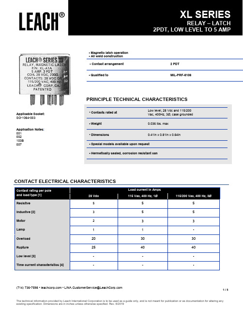
(714)736-7598••**********************************1 / 5• Magnetic latch operation • All weld construction• Contact arrangement2 PDT• Qualified toMIL-PRF-6106PRINCIPLE TECHNICAL CHARACTERISTICS• Contacts rated atLow level, 28 Vdc and 115/200 Vac, 400Hz, 3Ø, case grounded • Weight 0.036 lbs. max • Dimensions0.41in x 0.81in x 0.64in• Special models available upon request • Hermetically sealed, corrosion resistant canApplicable Socket: SO-1064-003Application Notes : 001 002 103B 007CONTACT ELECTRICAL CHARACTERISTICSContact rating per poleand load type [1] Load current in Amps28 Vdc 115 Vac, 400 Hz, 1Ø115/200 Vac, 400 Hz, 3ØResistive 5 5 5 Inductive [2] 3 5 5 Motor 23 3 Lamp 1 1 - Overload 20 30 30 Rupture 25 40 40 Low level [3]- - - Time current characteristics [4] ---COIL CHARACTERISTICS (Vdc)GENERAL CHARACTERISTICSUnless otherwise noted, the specified temperature range applies to all relay characteristics.CODEABCN [5]R [5]V [5]Nominal operating voltage 28 12 6 28 12 6 Maximum operating voltage @125°C 29 14.5 7.329 14.5 7.3 Maximum pickup voltage- Cold coil at +125° C18 9 4.5 18 9 4.5 - During high temp test at +125° C19.8 9.9 5 19.8 9.9 5 - During continuous current test at +125° C 22.5 11.25 5.7 22.5 11.25 5.7 Coil resistance in Ω ±10% at +25° C except types "C" and "R" +20%, - 10%7301824373018243Temperature range-70°C to +125°C [7] Minimum operating cycles (life) at rated load 100,000 [2] Minimum operating cycles (life) at 25% rated load 400,000 Dielectric strength at sea level- All circuits to ground and circuit to circuit 1000 Vrms - Coil to ground and coil to coil 500 Vrms Dielectric strength at altitude 80,000 ft 500 Vrms [6] Insulation resistance- Initial (500 Vdc)100 M Ω min - After environmental tests (500 Vdc) 50 M Ω minSinusoidal vibration (A, D and J mounting) 0.12 d.a. / 10 to 70 Hz 30G / 70 to 3000 Hz Sinusoidal vibration (G mounting) 0.12 d.a. / 10 to 57 Hz 20G /57 to 3000 Hz Random vibration- Applicable specification MIL-STD-202 - Method214- Test condition - A, D and J mounting 1G (0.4G2/Hz, 50 to 2000 Hz) - Test condition - G mounting 1E (0.2G2/Hz, 50 to 2000 Hz) - Duration15 minutes each plane Shock (A, D and J mounting) 200G / 6 ms Shock (G mounting)100G / 6 ms Maximum contact opening time under vibration and shock 10 μs Operate time at nominal voltage@25°C 4 ms max Release time at nominal voltage@25°C4 ms max Contact make bounce at nominal voltage@25°C 1.0 ms max Weight maximum0.036 lbs.MOUNTING STYLESDimensions in inchesTolerances, unless otherwise specified, ± 0.03 inTERMINAL TYPESDimensions in inchesTolerances, unless otherwise specified, ± 0.03 inDIAGRAMSTOL: .XX ±.03; .XXX ±.010NUMBERING SYSTEMNOTES1. Standard Intermediate Current test applicable; relay can also switch low level loads while switching any of the other rated loads on adjacent contacts.2. Inductive load life: 20,000 cycles.3. Low level endurance test: contact load of 10 to 50 millivolt, 10 to 50 microamp, 100 Ohm max. contact resistance.4. Refer to MIL-PRF-6106 for details.5. "N" "R" & "V" coils have back EMF suppression to 42 volts maximum.6. 500 Vrms with silicone rubber gasket compressed, 250 Vrms all other conditions.7. "N", "R" & "V" coils derated to 85° C.8. Reference MIL-PRF-6106/389.Relay will not be damaged, but may transfer with application of reverse polarity to coil.For any inquiries, please contact your local sales representative: XL- A 1 A- XXXBasic series designation1. Mounting styles (A, D, E, G, J)2. Terminal types (1, 2, 4,)3. Coil voltage, see coil characteristics (A, B, C, M, N, R, V)4. XXX DesignatorsDimensions in inchesTolerances, unless otherwise specified, ± 0.03 in。
三友SRD继电器规格书

机 械 寿 命 (每 小 时1 0 , 8 0 0次)
10,000,000 次
电 气 寿 命 (每 小 时1 , 8 0 0次)
100,000 次
-40℃~+105℃(不冷凝) 约8.5gLeabharlann 线圈参数 (at 20℃)
额定电压 (VDC)
3 5 6 9 12 15 18 24 48 60
120.00 71.42 60.00 40.00 30.00 24.00 20.00 15.00 7.50 6.00
寿命曲线
100 50
10 5
28VDC,250VAC阻性 1a 1c
0
5
10
15
触点电流(A)
60
50
40
10A
30
7A
20
0A
10
线圈温升
0 80 90 100 110 120 130 线圈电压额定值的百分比
3/3
订货标记
型号命名规则 SRD -S -1 12 D M 1 - F -XX
特殊参数:无-标准型,字母或数字-特殊要求
绝缘等级:无-普通型,B-Class B,F-Class F
触点材质:
C型动触点
A型动触点
B型动触点
无-AgSnO2φ2.8
无-AgSnO2φ3.0 无-AgSnO2φ3.0
1-AgCdOφ2.8
触点代码4: 7A 250VAC,Resistive&General use,NO&NC 10A 250VAC,Resistive&General use,NO
触点代码5: 7A 250VAC,Resistive&General use,NO&NC 10A 250VAC,Resistive&General use,NO
小型电磁继电器插座系列 说明书
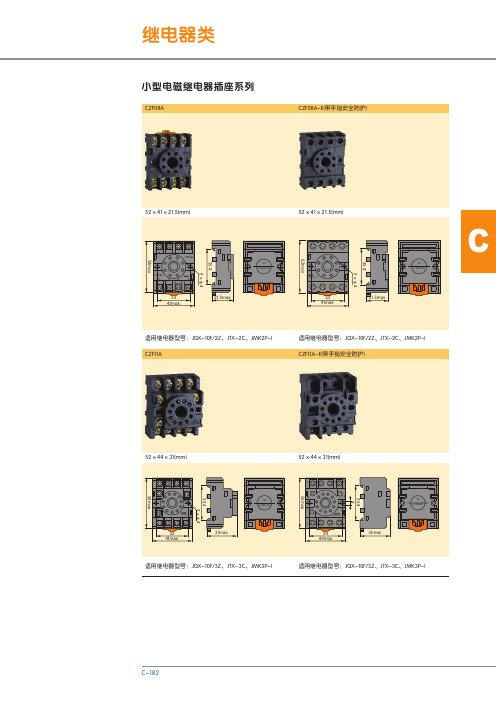
C小型电磁继电器插座系列CZF11A适用继电器型号:JQX-10F/3Z、JTX-3C、JMK3P-I适用继电器型号:JQX-10F/3Z、JTX-3C、JMK3P-I CZF08A CZF08A-E(带手指安全防护)适用继电器型号:JQX-10F/2Z、JTX-2C、JMK2P-I适用继电器型号:JQX-10F/2Z、JTX-2C、JMK2P-ICZF11A-E(带手指安全防护)CZT08B-01(宽体规格、铜带连接)适用继电器型号:JQX-13F(B)/2Z、NJX-13FW(B)/2Z、H H62P(-L)、LY2(N)CZT08A-02(窄体规格)适用继电器型号:JQX-13F(B)/2Z、NJX-13FW(B)/2Z、 H H62P(-L)、LY2(N)CZT08A-E(带手指安全防护)适用继电器型号:JQX-13F(B)/2Z、NJX-13FW(B)/2Z、HH62P(-L)、LY2(N)CZT08B-01E(宽体规格、铜带连接)适用继电器型号:JQX-13F(B)/2Z、NJX-13FW(B)/2Z、HH62P(-L)、LY2(N)CCZY11A适用继电器型号:JZX-22F(B)/3Z、NJX-13FW(B)/3ZS、HH53P(L)、MY3(N)CZY11A-E()带手指安全防护适用继电器型号:JZX-22F(B)/3Z、NJX-13FW(B)/3ZS、HH53P(L)、MY3(N)CZY08A-02(窄体规格)72×23×31(mm)适用继电器型号:JZX-22F(B)/2Z、NJX-13FW(B)/2ZS、JZX-18F(L)/2Z、 HH52P(L)、MY2(N)CZY08A-E(带手指安全防护)适用继电器型号:JZX-22F(B)/2Z、NJX-13FW(B)/2ZS、HH52P(L)、MY2(N)72×23×31(mm)CZY14A 72×30×31(mm)适用继电器型号:JZX-22F(B)/4Z、NJX-13FW(B)/4ZS、JZX-18F(L)/4Z、 HH54P(L)、MY4(N)CZY14A-E(带手指安全防护)72×30×31(mm)适用继电器型号:JZX-22F(B)/4Z、NJX-13FW(B)/4ZS、HH54P(L)、MY4(N)CZY08B-01(宽体规格、铜带连接)63×30.5×26(mm)适用继电器型号:JZX-22F(B)/2Z、NJX-13FW(B)/2ZS、JZX-18F(L)/2Z、 HH52P(L)、MY2(N)63×30.5×26(mm)适用继电器型号:JZX-22F(B)/4Z、NJX-13FW(B)/4ZS、HH54P(L)、JZX-18F(L)/4Z、 MY4(N)CZY14B(铜带连接)C63×30.5×26(mm)适用继电器型号:JZX-22F(B)/4Z、NJX-13FW(B)/4ZS、HH54P(L)、JZX-18F(L)/4Z、 MY4(N)CZY14B-E(带手指安全防护、铜带连接)适用继电器型号:JZX-22F(B)/3Z、NJX-13FW(B)/3ZS、HH53P(L)、MY3(N)CZY11B(铜带连接)63×30.5×26(mm)CZY08-02CZY11-02NG102NG103CZY14-02适用插座型号:CZT系列、CZY系列适用插座型号:CZY □B系列、CZT □B系列插座+挂钩。
技术规格书 固态继电器 SSK 2020(2)

与G2RL普通电磁式PCB焊接继电器外形一样的固态继电器SSK·交流型采用TRIAC输出,直流型采用功率晶体管输出;·内置RC突波吸收缓冲电路;·电压过零导通,电流过零关断(随机型可指定);·单列直插印刷基板安装,体积小,节省安装空间;·高电磁兼容性(EMC),适用恶劣工作环境;·接受OEM,ODM定制服务。
基本特性AC输出型号过零触发SSK4A2005 SSK4A2012 SSK4A2024 ——SSK4A20C 随机触发SSK4A2105 SSK4A2112 SSK4A2124 ——SSK4A21C输入额定工作电压5VDC 12VDC 24VDC ——电流10mA 适用电压范围4~6VDC 9.2~14.4VDC 19.2~28.8VDC ——电流5~15mA 输入阻抗(约) 0.5KΩ 1.5 KΩ 3.3 KΩ ————输出最大允许负载电流4A负载电压75~264VAC at 45~65Hz非重复浪涌电流30A峰值耐受电压600Vpeak导通压降最大1.2V at 2A关断状态漏电流最大3mA at 240VAC最小负载电流20mA动作/复位时间电源1/2周期+1ms 以下(随机型1ms以下) 触发类型过零导通过零关断(随机型可指定)基本特性DC输出型号SSK4D6105 SSK4D6112 SSK4D6124 SSK4D6132 SSK4D61C输入额定工作电压5VDC 12VDC 24VDC 5-24VDC 电流10mA 适用电压范围4~6VDC 9.2~14.4VDC 19.2~28.8VDC 3~32VDC 电流5~15mA 输入阻抗(约) 0.5KΩ 1.5 KΩ 3.3 KΩ ————输出最大允许负载电流4A负载电压5~60VDC非重复浪涌电流16A峰值耐受电压100Vpeak导通压降最大1.3V at 2A关断状态漏电流最大1mA at 60VDC 最小负载电流0.02mA动作/复位时间1ms 以下基本特性DC输出低内阻型型号SSK10D6105 SSK10D6112 SSK10D6124 SSK10D6132 SSK10D61C输入额定工作电压5VDC 12VDC 24VDC 5-24VDC 电流10mA 适用电压范围4~6VDC 9.2~14.4VDC 19.2~28.8VDC 3~32VDC 电流5~15mA 输入阻抗(约) 0.5KΩ 1.5 KΩ 3.3 KΩ ————输出最大允许负载电流10A负载电压0~60VDC非重复浪涌电流180A峰值耐受电压60Vpeak导通压降最大0.6V at 10A 关断状态漏电流最大1mA at 60VDC 最小负载电流0.02mA动作/复位时间1ms 以下基本特性DC输出交直流两用低内阻型型号SSK4K6105 SSK4K6112 SSK4K6124 ——SSK4K61C输入额定工作电压5VDC 12VDC 24VDC ——电流10mA 适用电压范围4~6VDC 9.2~14.4VDC 19.2~28.8VDC ——电流5~15mA 输入阻抗(约) 0.5KΩ 1.5 KΩ 3.3 KΩ ————输出最大允许负载电流4A负载电压0~60VDC/AC非重复浪涌电流180A峰值耐受电压60Vpeak导通压降最大1.2V at 4A关断状态漏电流最大0.01mA at 60VDC 最小负载电流0.02mA动作/复位时间1ms 以下通用特性型号SSK4A SSK4D SSK10D SSK4K适配底座PCB焊接G2R-1-SSG镀金绿色G2R-2-SSG镀金绿色导轨安装RS-ZE2M-35M RS-ZE2M-48M介质耐压2500VAC 50/60Hz 1min绝缘电阻1000MΩ以上(DC500V兆欧表)振动10~55Hz 双振幅0.75mm冲击1000m/s²使用/储藏环境温度-30℃~+80℃/30℃~+100℃无凝露,无结冰使用环境湿度45%~85%RH质量约20g1)所有技术特性参数均以25℃环境温度为测试条件,除非另有说明;2)介质耐压和绝缘电阻适用于输入和输出端之间。
安川继电器选型手册
YASKAWACONTROL安川车辆用插入式继电器使用指南型号:RB4P-G□□DC/D110RB3P-G□□DC/D110RB-3P5□□V2CL/D110明幸贸易(上海)有限公司正向垂直壁面或垂直水平面壁面水平面标准产品规格书品名中容量元件内置型车辆用插入式继电器型号 RB4P-G□□DC/D1101.适用本规格书适用于中容量元件内置型车辆用插入式继电器(型号:RB4P-G□□DC/D110).2.外形图外形图如S44484所示。
3.规格书的构成本规格书由以下几个项目构成。
(1)规格(2)完成品的出货检查(3)标识以及包装规格(4)使用注意事项(5)其他(6)用语说明4.规格4.1操作线圈规格·特性*1.环境温度20℃下适用。
*2.使用温度范围(-40℃~+70℃)下适用。
4.2接点规格以及特性注)请参照表4 的用语。
5.完成品检查收到产品后,请按照下面的内容进行检查。
表3.完成品检查完成品检查成绩表在产品出厂后10年间,请品质管理科保管。
用于保证维护品质。
6.标识·包装规格1)产品的跟踪标准:在产品的侧面用黑色的TAT墨水印上2位的生产批次编码。
例如:“E5”……2010年5月的产品生产批次E:显示年(2010年是E,2011年是F,按照罗马字母顺序依次类推。
)5:显示月(1~9月是数字1~9,10月11月12月是字母XYZ)完成品检验合格后在包装箱上印上合格印记。
2)包装时要考虑到运输过程中可能遇到的破损以及雨水湿气的侵害情况,尽力避免。
7.使用注意事项1)请避免跌落。
万一跌落,请先检查玻璃破裂以及动作特性,确认无异常后再使用。
2)线圈有极性,请将端子符号①接在+极,将⑾接在-极。
此外,线圈驱动电源请使用电池电源的完全直流或者三相全波整流那样波动率5%以下的电源。
3)线圈驱动回路请使用施加额定电压的直投法(瞬时ON,瞬时OFF)。
线圈施加电压逐渐增大,以及逐渐减小的线圈驱动回路时,会造成电气寿命变短。
继电器 规格书

FTR-K1 SERIESn FEATURESl1 pole, 32Al1 form A contactl Wide contact gap: 1.8mmDielectric strength (B/T open contacts) 2.5kVCompliant with European photovoltaic standard (VDE0126) Array and inverter safety standard (IEC62109-2)l High insulation in small package (between coil and contacts)- Dielectric strength: AC 4,000V- Surge strength: 6,000Vl Low coil power consumption: 1,400mWl Coil holding voltage can be reduced up to 35% of nominalcoil voltage (ambient temperature; +20 °C, contact current; 32A)Power consumption at the lowest coil holding voltage; 170mW* Coil holding voltage is the coil voltage after 100ms ofapplied nominal coil voltagel Plastic materials: Flammability; UL94 V-0l Cadmium-free contactsl Flux free, cat. RTII protectionl RoHS compliant.n PARTNUMBER INFORMATIONFTR-K3 A B 012 W - PS[Example] (a) (b) (c) (d) (e) (f)(a) Relay type FTR-K3 : FTR-K3-Series(b) Contact configuration A : 1 form A / PCB type(c) Coil power B : Standard (1,400mW)(d) Coil rated voltage 012 : 5.....48 VDCCoil rating table at page 3(e) Contact material W : Silver alloy(f) Option code PS : High current (32A) / contact gap 1.8mmn SPECIFICATION*1 Minimum switching loads mentioned above are reference values. Please perform the confirmation test with actualload before production since reference values may vary according to switching frequencies, environmental conditionsnCOIL RATINGType Compliance Contact ratingULUL 508Flammability: UL 94 V0 (plastics)32A, 277VAC (General use, at 85 °C)CSA 22.2 No.14 (approved by cULus)VDEIEC61810-132A, 250VAC (cos φ = 0.8, at 85 °C)n SAFETY STANDARDSNote: All values in the table are valid for 20°C and zero contact current.* Specified operate values are valid for pulse wave voltage.n DIMENSIONSl Dimensionsl PC board mounting hole layout(BOTTOM VIEW)lSchematics (BOTTOM VIEW)1. General InformationlAll signal and power relays produced by Fujitsu Components are compliant with RoHS directive 2002/95EC includingamendments.l Cadmium as used in electrical contacts is exempted from the RoHS directives on October 21st, 2005. (Amendment to Directive 2002/95/EC)l All of our signal and power relays are lead-free. Please refer to Lead-Free Status Info for older date codes at: /us/downloads/MICRO/fcai/relays/lead-free-letter.pdfl Lead free solder plating on relay terminals is Sn-3.0Ag-0.5Cu, unless otherwise specified. This material has been verified to be compatible with PbSn assembly process.2. Recommended Lead Free Solder ProfilelRecommended solder Sn-3.0Ag-0.5Cu.RoHS Compliance and Lead Free Information3. Moisture SensitivitylMoisture Sensitivity Level standard is not applicable to electromechanical relays, unless otherwise indicated.4. Tin WhiskerslDipped SnAgCu solder is known as presenting a low risk to tin whisker development. No considerable length whisker was found by our in house test.We highly recommend that you confirm your actual solder conditionsFlow Solder condition:Pre-heating: maximum 120˚CSoldering: dip within 5 sec. at260˚C solder bathSolder by Soldering Iron:Soldering Iron Temperature: maximum 360˚C Duration:maximum 3 sec.Fujitsu Components International Headquarter OfficesJapanFujitsu Component LimitedGotanda-Chuo Building3-5, Higashigotanda 2-chome, Shinagawa-ku Tokyo 141, JapanTel: (81-3) 5449-7010Fax: (81-3) 5449-2626Email: promothq@Web: North and South AmericaFujitsu Components America, Inc.250 E. Caribbean DriveSunnyvale, CA 94089 U.S.A.Tel: (1-408) 745-4900Fax: (1-408) 745-4970Email: components@Web: /components EuropeFujitsu Components Europe B.V.Diamantlaan 252132 WV HoofddorpNetherlandsTel: (31-23) 5560910Fax: (31-23) 5560950Email: info@Web: /components/Asia PacificFujitsu Components Asia Ltd.102E Pasir Panjang Road#01-01 Citilink Warehouse ComplexSingapore 118529Tel: (65) 6375-8560Fax: (65) 6273-3021Email: fcal@Web: /sg/services/micro/components/©2012 Fujitsu Components Europe B.V. All rights reserved. All trademarks or registered trademarks are the property of their respective owners. The contents, data and information in this datasheet are provided by Fujitsu Component Ltd. as a service only to its user and only for general information purposes.The use of the contents, data and information provided in this datasheet is at the users’ own risk.Fujitsu has assembled this datasheet with care and will endeavor to keep the contents, data and information correct, accurate, comprehensive, complete and up to date.Fujitsu Components Europe B.V. and affiliated companies do however not accept any responsibility or liability on their behalf, nor on behalf of its employees, for any loss or damage, direct, indirect or consequential, with respect to this datasheet, its contents, data, and information and related graphics and the correctness, reliability, accuracy, comprehensiveness, usefulness, availability and completeness thereof.Nor do Fujitsu Components Europe B.V. and affiliated companies accept on their behalf, nor on behalf of its employees, any responsibility or liability for any representation or warrant of any kind, express or implied, including warranties of any kind for merchantability or fitness for particular use, with respect to these datasheets, its contents, data, information and related graphics and the correctness, reliability, accuracy, comprehensiveness, usefulness, availability and completeness thereof. Rev. March 15, 2012。
欧姆龙继电器手册

*LY1-0 *LY2-0 **LY2Z-0 *LY3-0 *LY4-0
― ― ― ― ―
*LY1F *LY2F **LY2ZF *LY3F *LY4F
― ― ― ― ―
ܡ䌍 ⬉䆱
䆶⬉䆱 400-820-4535
᳔ᮄֵᙃ
1
LY
种类
● 插座端子型
(线圈规格仅限DC)
2 双
*LY2 **LY2Z *LY3 *LY4 **LY1-D **LY2-D **LY2Z-D
**LY2N **LY2ZN **LY3N **LY4N **LY1N-D2 **LY2N-D2 **LY2ZN-D2
3
**LY3-D
**LY3N-D2
线圈浪涌吸收用CR回 路型
型号 LY4 LY4N
― LY4N-D2
4极 额定电压 (V)
AC100/110、200/220 DC24 AC100/110、200/220 DC24
― DC24
最小订购数量 (个)
10
ܡ䌍 ⬉䆱
䆶⬉䆱 400-820-4535
᳔ᮄֵᙃ
2
LY
额定规格/性能
型号 LY4
LY4N LY4-D
4极 额定电压 (V) AC12、24、 100/110、200/220 DC12、24、48、 100/110
AC12、24、 100/110、200/220 DC12、24、48、 100/110 DC12、24、48、 100/110
LY2N-D2
DC12、24、48、 100/110
DC12、24、48、 100/110
型号 LY3
LY3N LY3-D
3极 额定电压 (V) AC12、24、 100/110、200/220 DC12、24、48、 100/110
TE泰科RTD34012继电器规格书

n 1 pole 12A/16A, 1 form C (CO) or 1 form A (NO) contact n DC or AC coiln 5kV/10mm coil-contact, reinforced insulation n Ambient temperature 85°C (DC coil)n WG version: product in accordance to IEC 60335-1n Reflow version: for THR (Through-Hole Reflow) soldering processTypical applicationsBoiler control, timers, garage door control, POS automation, interface modulesApprov a lsVDE Cert. No. 40007571, cULus E214025, cCSAus 1142018; CQC in preparationTechnical data of approved types on requestContact Data 12A 16AContact arrangement 1 form C (CO) or 1 form A (NO) Rated voltage 250VAC Max. switching voltage 400VAC Rated current 12A 16A Limiting continuous current 12A 16A, UL: 20A Limiting making currentmax. 4s, duty factor 10% 25A 30A Breaking capacity max. 3000VA 4000VA Contact material A gNi 90/10, AgNi 90/10 gold plated Frequency of operation, with/without load DC coil 360/72000h -1 AC coil 360/36000h -1Operate/release time max., DC coil 8/6ms Bounce time max., DC coil, form A/form B 4/6ms Electrical endurance see electrical endurance graph 1)Contact ratings Type Contact Load Cycles IEC 61810RT314 DC-coil A (NO) 16A, 250VAC, cos φ=1, 85°C 30x103 RT314 DC-coil C (CO) 16A, 250VAC, cos φ=1, 85°C 10x103 RT314 DC-coil A (NO) 10A, 400VAC, cos φ=1, 85°C 150x103 RT114 DC-coil A (NO) 12A, 250VAC, cos φ=1, 85°C 50x103 RT114 AC-coil A (NO) 12A, 250VAC, cos φ=1, 70°C 100x103UL 508 RT314 A/B (NO/NC) 20A, 250VAC, general purpose, 85°C 6x10³ RT334 A (NO) 16A, 250VAC, gen. purpose, 85°C 50x103 RT314 A (NO) 1hp, 240VAC, 40°C 1x10³ RT314 A (NO) FLA/LRA, 4.5/13.1A, 480VAC, 70°C 100x 103EN60947-5-1RT314 DC-coil A/B (NO/NC) 2A, 24VDC, DC13 6.050EN60730-1RT314 DC-coil A (NO) 12(2)A, 250VAC, 85°C 100x103reflow soldering process.Contact Data (continued)Mechanical endurance DC coil >30x106 operations AC coil>10x106 operations AC coil, reflow version>5x10⁶ operationsCoil DataCoil voltage range, DC coil/ AC coil 5 to 110VDC / 24 to 230VAC Operative range, IEC 61810 2Coil insulation system according UL class FCoil versions, DC coil Coil Rated Operate Release Coil Rated coil code voltage voltage voltage resistance powerVDC VDC VDC Ω±10%2) mW005 5 3.5 0.5 62 403 006 6 4.2 0.6 90 400 009 9 6.3 0.9 200 400 012 12 8.4 1.2 360 400 020 20 14.0 2.0 952 420 024 24 16.8 2.4 1440 400 048 48 33.6 4.8 5520 417 060 60 42.0 6.0 85702) 420 110 110 77.0 11.0 288002) 4202) Coil resistance ±12%.All figures are given for coil without pre-energization, at ambient temperature +23°C.Other coil voltages on request.Coil versions, AC coil 50/60 Hz Coil Rated Operate Release Coil Rated coil code voltage voltage voltage resistance power VAC VAC VAC Ω±15%3) VA 524 24 18.0 3.6 3503) 0.76 615 115 86.3 17.3 8100 0.76 620 120 90.0 18.0 8800 0.75 700 200 150.0 30.0 24350 0.76 730 230 172.5 34.5 32500 0.743) Coil resistance ±10%.All figures are given for coil without pre-energization, at ambient temperature +23°C, 50 Hz.Power PCB Relay RT1F0144-CZ bOther Data (continued)Terminal typestandard version PCB-THT, plug-in reflow version PCB-THR Mounting distance AC coil: ≥2.5mm Weight 14g Resistance to soldering heat THT, IEC 60068-2-20 RTII 270°C/10s RTIII 260°C/5s Resistance to soldering heat THRreflow soldering (for reflow version) forced gas convection 4) or vapour phase 5) temperature profile according EN61730Packaging/unit tube/20 pcs., box/500 pcs.4) infrared heating not allowed 5) recommended fluid LS/230AccessoriesFor details see datasheet A ccessories Industrial Power Relay RT NOTE: indicated contact ratings and electrical endurance data for direct wiring of relays (according IEC 61810-1); for relays mounted on sockets deratings may apply.Insulation DataInitial dielectric strength between open contacts 1000V rms between contact and coil 5000V rms Clearance/creepagebetween contact and coil ≥10/10mmMaterial group of insulation parts IIIa Tracking index of relay base PTI 250V reflow versionPTI 175VOther DataMaterial compliance: EU RoHS/ELV , China RoHS, REACH, Halogen content refer to the Product Compliance Support Center at /customersupport/rohssupportcenter Resistance to heat and fireWG version or Reflow version according EN60335, par30Ambient temperatureDC coil -40 to 85°C AC coil -40 to 70°C Category of environmental protection, IEC 61810 standard version R TII - flux proof, RTIII - wash tight reflow version RTII - flux proof Vibration resistance (functional)form A/form B contact, 30 to 500Hz 20g/5g Shock resistance (destructive)100gPCB layout / terminal assignmentBottom view on solder pins12 A , pinning 3.5 mm12 A , pinning 5 mm16 A , pinning 5 mmS0163-BES0163-BC S0163-BG S0163-BH S0163-BD S0163-BF*) With the recommended PCB hole sizes a grid pattern from 2.5 m m to 2.54 m m can be used.Product code structureTypical product codeRT 3 1 4 024Type RT Power PCB Relay RT1Version 1 12A, pinning 3.5mm, flux proof 2 12A, pinning 5mm, flux proof *) 3 16A, pinning 5mm, flux proof B 12A, pinning 3.5mm, wash tight D 16A, pinning 5mm, wash tight Contact arrangement 1 1 form C (CO) contact 3 1 form A (NO) contact Contact material 4 AgNi 90/10 5 AgNi 90/10 gold plated (for type RT31.)Coil Coil code: please refer to coil versions table Version Blank Standard version WG Product in accordance with IEC 60335-1 (domestic appliances) R Reflow solderable*) Wash tight version on requestDimensionsProcess conditions for Reflow soldering according to EN61760-1THT version THR version (reflow solderable)Product codeVersionContactsContact materialCoilVersionPart numberRT114009 12A, pinning 3.5mm, 1 form C (CO) AgNi 90/10 9VDC Standard 1393239-9 RT114012 flux proof contact 12VDC 1419108-1 RT114012WG IEC60335-1 compliant 7-1415538-6 RT114024 24VDC Standard 1-1393239-3 RT114024WG IEC60335-1 compliant 1415539-4 RT114730 230VAC Standard 1-1393239-9 RT115024 AgNi 90/10 gold pl. 24VDC 2-1393239-1 RT134012 1 form A (NO) AgNi 90/10 12VDC 2-1393239-6 RT134024 contact 24VDC 3-1393239-0 RT214012 12A, pinning 5mm, 1 form C (CO) 12VDC 5-1393239-4 RT214024 flux proof contact 24VDC 5-1393239-5 RT214524 24VAC 5-1393239-9 RT214730 230VAC 1419108-6 RT314005 16A, pinning 5mm, 5VDC 9-1393239-1 RT314006 flux proof 6VDC 9-1393239-3 RT314012 12VDC 9-1393239-5 RT314012WG IEC60335-1 compliant 8-1415535-6 RT314024 24VDC Standard 9-1393239-8 RT314024WG IEC60335-1 compliant 1415538-7 RT314048 48VDC Standard 1393240-1 RT314730 230VAC 1393240-7 RT315024 AgNi 90/10 gold pl. 24VDC 1-1393240-4 RT334009WG 1 form A (NO) AgNi 90/10 9VDC IEC60335-1 compliant 3-1415538-1 RT334012 contact 12VDC Standard 4-1393240-5 RT334012WG IEC60335-1 compliant 1-1415527-1 RT334024 24VDC Standard 4-1393240-8 RT334048 48VDC 5-1393240-0 RTB14005 12A, pinning 3.5mm, 1 form C (CO) 5VDC 1-1393238-2 RTB14012 wash tight contact 12VDC 1-1393238-5 RTB14024 24VDC 1-1393238-9 RTB14524 24VAC 2-1393238-4 RTD14005 16A, pinning 5mm, 5VDC 5-1393238-9 RTD14012 wash tight 12VDC 6-1393238-2 RTD14024 24VDC 6-1393238-8 RTD14048 48VAC 6-1393238-9 RTD34012 1 form A (NO) 12VDC 3-1419108-5 RTD34024 contact 24VDC 3-1419108-8 This list represents the most common types and does not show all variants covered by this datasheet.。
通灵T78继电器规格书

1.Relay ModelTRKM or 3.Contact conversionHJR-78F 2.Coil Nominal Voltage 5,6,9,12,24VDCZ:Form C B:Form BH:Form A东海县通灵电器有限公司PCB 继电器●20A switching capability ●Small size auto relay●Conform to RoHS,ELV directive15.7*12.3*14ORDERING CODETL-T78DC12VA123■COIL DATA (at 20℃)Nominal Voltage (VDC)5691224Coil Resistance (Ω±10%)7010022540016000.36WRated Current (mA)71.460403015Max Operate Voltage (VDC) 3.75 4.5 6.759.018.0Min Release Voltage (VDC)0.400.480.720.96 1.92Coil Resistance (Ω±10%)42601352409600.6W Rated Current (mA)11910066.75025Max Operate Voltage (VDC) 3.25 3.9 5.857.815.6Min Release Voltage (VDC)0.400.480.720.96 1.92Coil Resistance (Ω±10%)31451001807200.8W Rated Current (mA)161.3133.388.966.733.3Max Operate Voltage (VDC) 3.25 3.9 5.857.815.6Min Release Voltage (VDC)0.400.480.720.961.92Max ApplicableVoltage130%of rated voltage at 70℃,170%of rated voltage at 23℃JQC-T78■ENGINEERING DATAservice life current50020115cu10rren5 1.DC resistive2.AC resistiveOperati on(X100 00)1005010t(3A)2load1Contact0.50.30.13.ACresistiveContact Current(A)temperatureContact load voltage(V))80℃Ris 70e(60No contact carrying0Te mp era tur e Co il 50current40302010Vc/Vr0.60.70.80.91 1.23■OVERALL AND MOUNTING DIMENSIONS安装图安装图接线图Form CForm AForm BREMARK(备注):1、产品部分外形尺寸中未注尺寸公差:当外形尺寸≤1mm时,公差为±0.2mm;当外形尺寸在1~5mm时,公差为±0.3mm;当外形尺寸>5mm时,公差为±0.4mm。
nexem继电器eb2规格书
nexem继电器eb2规格书一、产品介绍nexem继电器eb2是一种高品质、高性能的继电器,专为电气控制系统设计。
该继电器能够稳定可靠地控制电路的通断,广泛应用于工业自动化、电力系统、交通运输等领域。
二、技术参数1. 输入电压范围:5VDC、12VDC、24VDC2. 输出电压范围:220VAC、380VAC3. 最大负载电流:10A、20A、30A4. 绝缘电阻:100MΩ以上5. 工作温度范围:-40°C至+85°C6. 连通电阻:100mΩ以下7. 绝缘强度:2000VAC8. 机械寿命:100万次以上三、产品特点1. 高可靠性:采用优质材料和先进工艺制造,具有良好的抗干扰能力和稳定的工作性能。
2. 超长寿命:精选优质电器元器件,可实现100万次以上的机械寿命,确保设备长期稳定运行。
3. 多种规格可选:输入电压、输出电压、负载电流等多种规格可供选择,满足不同用户的需求。
4. 安装简便:结构紧凑,安装方便,适用于各种环境要求。
四、应用领域nexem继电器eb2广泛应用于各种工业控制系统和电气设备中,包括但不限于:1. 电力系统:变压器、继电保护装置、开关设备等;2. 工业自动化:数控机床、工业机器人、自动包装线等;3. 交通运输:地铁系统、铁路信号系统、电动车辆控制系统等;4. 建筑设备:空调控制、电梯控制、消防设备等。
五、质量保证1. 本产品严格按照国际标准生产,通过ISO9001质量管理体系认证,保证产品工艺稳定、质量可靠。
2. 所有产品在出厂前均经过严格的测试和检查,确保产品性能符合规格要求。
3. 我们提供一年质量保证期,对因产品质量问题引起的故障进行免费维修或更换。
六、结语nexem继电器eb2以其高品质、高性能、高可靠性赢得了广大用户的信赖和好评,我们将一如既往地致力于为客户提供更优质的产品和更专业的服务,与客户共同发展,共创美好未来!针对nexem继电器eb2的性能和应用领域,我们可以进一步展开讨论。
- 1、下载文档前请自行甄别文档内容的完整性,平台不提供额外的编辑、内容补充、找答案等附加服务。
- 2、"仅部分预览"的文档,不可在线预览部分如存在完整性等问题,可反馈申请退款(可完整预览的文档不适用该条件!)。
- 3、如文档侵犯您的权益,请联系客服反馈,我们会尽快为您处理(人工客服工作时间:9:00-18:30)。
TYPE: GH SERIES
⏹ MODEL DATE
Terminal style
Contact form
UL Insulation System approval
Designation (provided with)
Flux tight Sealed type
Sealed type
washable PCB terminal
SPDT (1C )
B
GH-1C-12LF-C GH-1A-12LF GH-1C-12LF-S F
GH-1C-12L-C-F
GH-1C-12L-F
GH-1C-12L-S-F
⏹ CONTACT DATE Type
GH-1A-12LF Resistive load
10A 250VAC
Max. switching current 12A Max. switching voltage 250VAC Max. switching capacity 3,000VA
⏹ SAFETY APPROVAL
Certified CQC
TUV
UL/CUL File No.
CQC14002105590
R50158866
E321783
⏹ SAFETY APPROVAL RATING
CQC TUV
UL/CUL
10A 250VAC 7A 250VAC
7A 250VAC, cos phi=1 10A 250VAC, cos phi=1 12A 250VAC, cos phi=1
NO: 12A 125VAC 12A 125VAC NO: 10A 277VAC 10A 277VAC NO: 1/3HP 277VAC 1/3HP 277VAC NO: TV-5 120VAC TV-5 120VAC
⏹ ORDERING INFORMATION
Contact type:A--normally open;B--normally closed;C--double throw
Coil power:L--0.36w;D--0.45w;H--0.8w
Contact pole:1--1 pole Basic series designation
Coil voltage(VDC):3,4,5,6,9,12,15,18,24,36,48
Enclosure:Blank--Sealed type C--Flux tight S--Sealed type washable
Enamelled Wire:Blank--130Cused in maximum 85℃ C S.A.T F: 155C used in maximum 105C S.A.T
GH - 1 C - 12 L C F X
Special parameters:
Any number or alphanic(not affect the construction and performance )
Blank--No feature;G--Big gap ≥1.0mm;T--Glowing filament plastic;
TYPE: GH SERIES ⏹COIL DATA (At 20℃)
Rated Voltage (VDC)
Rated
current
±10% (mA)
Coil
resistance
±10%
Max.
continuous
Voltage
Pick up
Voltage
(Max)
Drop out
Voltage
(Min)
Power
consumption
at rated
voltage
3 120 25
130 % of Rated voltage 75 % of
Rated
voltage
5 % of
Rated
voltage
Approx.
0.36W
5 71.42 70
6 60 100 9 40 225 12 30 400 18 20 900 24 15 1600 48 7.5 6400
3 150 20
130 % of Rated voltage 75 % of
Rated
voltage
5 % of
Rated
voltage
Approx.
0.45W
5 90 55.6
6 75 80
9 50 180
12 37.5 320
18 25 720
24 18.75 1280
48 9.4 5120
⏹SPECIFICATION
Contact material Silver alloy
Contact resistance( Initial ) 100MΩMax.
Operate time 10ec Max.
Release time 5msec Max. Insulation system 250mΩMin.(DC500V)
Dielectric strength Between open contacts: AC750V, 50/60Hz for 1min. Between coil and contact: AC1500V, 50/60Hz for 1min
Vibration resistance Functional 10~55Hz at double amplitude of 3.3 Destructive 10~55Hz at double amplitude of 3.3
Shock resistance Functional 100m/s²11ms Destructive 100m/s²11ms
Expected
Service Endurance Mechanical Endurance 10,000,000 cycles (10,800 cycles/h) Electrical Endurance 100,000 cycles (1,800 cycles/h)
Ambient temperature -40℃~+105℃(No condensation) Weight Approx. 9.5g
TYPE: GH SERIES
OUTLINE DIMENSIONS
×
TOLERANCE:
LESS THAN:1±0.2 5±0.3 MORE THAN:5±0.4
WIRING DIAGRAM
1A 1C
BOTTOM VIEW
PC BOARD LAYOUT
1
2.
22
12
64- 1.3
12.2
2
12
65- 1.3
1A 1C
TOLERANCE: ±0.1 BOTTOM VIEW
ITEM
GH OUTLINE
VERSION UNIT DATE V1.0 mm 2013-8-1 DONGGUAN GOLDEN ELECTRICAL APPLIANCES CO.LTD
APPROVED
CHECKED
DRAW
TYPE: GH SERIES
⏹ Marking and Printing
NOTE:
1 Marking “C1307-C ” is the production date and batch
number
2 The meaning of the marking according to below:
3 May have no the marking if customer have no demand
Eng. Change Initial Issued
2013-8-1
DONGGUAN GOLDEN ELECTRICAL APPLIANCES CO.LTD
Unit mm Version V1.1 Approval
Review
Drawn by
ITEM Marking and Printing
Model
GH
TYPE: GH
⏹ PACKING SPECIFICATION
Inner Packiage-1Inner Packiage-2
100PCS/Tray 100PCS/Tray*10Tray
External Package
2*( 100PCS/Tray*10Tray)
DONGGUAN GOLDEN ELECTRICAL APPLIANCES CO.LTD Unit mm Version V1.1 Approval Review Drawn by
ITEM PACKING SPECIFICATION Model GH。
