THKA多回路智能工业调节器
智能调节器的作用
智能调节器是一种数字化的过程控制仪表,以微处理器或单片微型计算机为核心,具有数据通信功能,能完成生产过程1~4个回路直接数字控制任务,在DCS的分散过程控制级中得到了广泛的应用。
智能调节器不仅可接受4~20mA DC电流信号输入的设定值,还具有异步通信接口RS-422/485、RS-232等,可与上位机连成主从式通信网络,发送接收各种过程参数和控制参数。
智能调节器在我国的工业控制领域得到了广泛应用。
艾驰商城是国内最专业的MRO工业品网购平台,正品现货、优势价格、迅捷配送,是一站式采购的工业品商城!具有10年工业用品电子商务领域研究,以强大的信息通道建设的优势,以及依托线下贸易交易市场在工业用品行业上游供应链的整合能力,为广大的用户提供了传感器、图尔克传感器、变频器、断路器、继电器、PLC、工控机、仪器仪表、气缸、五金工具、伺服电机、劳保用品等一系列自动化的工控产品。
如需进一步了解相关仪器仪表产品的选型,报价,采购,参数,图片,批发等信息,请关注艾驰商城/。
智能调节器使用说明书
SIC-03型━━━━━━━━━━━━━━━━━组合型智能调节器智能调节器安装使用说明书━━━━━━━━━━━━━━━━━大连工业大学━━━━━━━━━━━━━━━━━大连工业大学一、概述一、概述本型号调节器是基于MCU(微型工业处理器)的新一代调节器,硬件设计上采用最新的微处理器技术及IC技术。
软件设计上采用成熟、可靠的控制算法,全部程序采用汇编语言实现,效率高、速度快。
显示功能完善:测量值、设定值、两参数在前面板同时以光柱和数码管两种形式显示,光柱用于以百分数形式显示两参数,数码管用于以工程量形式显示两参数;输出值以数字形式显示,阀位值以光柱形式显示,所有操作过程中关心的参数:测量值、设定值、输出值、阀位值、自动/手动控制方式、内/外给定方式、正/反作用方式在调节器的前面板上同时显示,不必按键选择显示,方便对控制过程的监控。
操作简单:仅通过前面板上四个按键,可实现对设定参数、实时参数的监测,其中,需要经常整定的PID参数、手动/自动切换操作,专门设计了简洁的操作方法,方便操作。
支持RS-485总线,有专门的通讯协议,方便构成现场总线测控系统。
二、主要功能与技术指标主要功能:1.自动/手动双向无平衡无扰动。
2.积分、微分作用可切除。
3.重要参数:被控变量给定值与测量值以数字形式与光柱形式同时显示;被控变量的工程量与满量程百分数同时显示;被控变量给定值、测量值、调节器输出值、阀位值、自动/手动状态、内/外给定形式、正/反作用方式同时在仪器的前面板上显示,不用任何操作,可完全了解调节器的工作情况。
4.支持RS-485通讯技术,方便构成局域控制网络。
5.当被控变量测量信号出现故障(小于2mA)时,阀位可保持在原有位置或自动切换到预置位置上。
主要技术指标:⒈输入信号⑴来自现场变送器的 4~20mA 电流信号或配电器输出的1~5V电压信号,两种信号可通过按键选择。
⑵外给定信号:4~20mA 电流信号。
⑶阀位信号:4~20mA 电流信号。
高流直挂NAMUR阀门电磁阀系列产品简介说明书
Fluid Control Division Global Marketing Update High Flow Valve Actuation SeriesGlobal Marketing Update No. 134, June 14, 2007 __________________________________________________________________________________________________________________________________ Parker Fluid ControlDivision is continually expanding its Valve Actuation product portfolio to meet the ever increasing demands of the process industry. Our goal is to provide the highest quality feature enhanced portfolio to the actuation segment of the process industry.We are pleased to introduce our new Series of High Flow direct mount NAMUR solenoid valves for the Process and Industrial markets. The High Flow Series complements our highly successful specification grade 7300 Series product line. The High Flow product line provides new, cost effective solutions for general purpose customer application needs.Attachments and EnclosuresI Catalog BrochureII List Price SheetIII Installation, Operation andMaintenanceInstructionsIV Competitive FeatureComparisonV CompetitiveCross-Reference ValveListing PRODUCT FEATURESThe High Flow Series is a NAMUR interfaceinternal pilot spool valve for direct mounting toactuators. The NAMUR mount spool valve isavailable for either 3/2 normally closed valveor 5/2 four-way functionality.The axial valve construction allowsa low profile or in-line operatororientation with valve body valve style.The portfolio consists of 1/4” ported single and dual solenoid valves (Cv = 1.2) and a larger high flow 1/2” ported valve (Cv = 3.0) meeting a wide variety of application requirements. (Reference catalog pages and construction reference drawings)The valve body is a hard anodized aluminum. The standard pressure vessel end cap is made of an engineered thermoplastic.The primary valve characteristic is a patented “swimming” o-ring sealing system that increases sealing force as pressure increases thereby minimizing stiction potential at lower pressures. The valve series incorporates numerous other benefits including: •Utilizing a combined pneumatic and spring return for standard fail-safe operation in case of power failure.•The valves are equipped with a standard locking manual override.•The valve uses a “bug screen” nut exhausting the pilot section of the valve to atmosphere for safe outdoor service.•Mounting plates are available for use with the hazardous coils.The spool valve design uses a low power coil for reduced energy consumption and computer base control. DIN, conduit and hazardous coils complete the electrical portfolio.Global Marketing Update No. 134, June 14, 2007 __________________________________________________________________________________________________________________________________ OPERATION FUNCTIONALITY3/2 Single Solenoid (4 ported, 2 position)NAMUR valve, solenoid operated, for 3-way normally closed operation. In case of an electrical or air failure, valve returns to a fail-safe position through pneumatic and assisted spring return.5/2 Single Solenoid (5 ported, 2 position)NAMUR valve solenoid operated, for 4-way, 2 position operation. In case of an electrical or air failure, valve returns to a fail-safe position through pneumatic and assisted spring return.5/2 Dual Solenoid (5 ported, 2 position)NAMUR valve used for 4-way, 2-position operation. In case of an electrical or air failure, valve “fails as is”. Therefore, valve remains in last position upon failure and will not return to a predetermined position.5/3 Dual Solenoid, Center Position Closed (5 ported, 2 position)NAMUR valve used for 4-way, 2-position operation. In case of an electrical or air failure, the spool returns to the center position thereby removing pressure to the cylinder ports.TECHNICAL PRODUCT CHARACTERISTICSThe new line of valve actuation products offer many features and benefits as follows:Modular construction – Facilitates use of various body configurations and coil options.Mounting Configurations - Direct mount NAMUR pattern with axial operator orientation for single and dual solenoid models for low profile mounting requirements.Manual Override – Standard on all models for manual valve operation during start-up and diagnostic procedures.7mm (1.2Cv ) and 12mm (3.0 Cv) orifice sizes – Multiple sizes to meet various application demands to ensure the solenoid valve is properly sized.Body Materials - Lightweight anodized aluminum.Spool Design – Stainless steel with NBR sealing materials.Exhaust Pilot Cap– Protected pilot sleeve exhaust using “Bug Screen” nut. Helps protect against plugging, dirt, and insects, etc.Ratings – Meets pressures up to 150 psi.Ambient Temperatures – From 14°F (-10°C) to 122°F (50°C), serving most temperature environments. Fluid Temperatures – From 32°F (0°C) to 104°F (40°C).COIL PRODUCT CHARACTERISTICSA selection of low power encapsulated coils as follows:•DIN coil - with 3-pin DIN 43650 type B plug.•Conduit - 3-wire coil.•Hazardous – 3-wire coil with FM and CSA agency approvals meeting Class 1, Groups A,B,C,D and Class II, Groups E,F,G. Meets EEx m II T4 Division 1 requirements.NAMUR INTERFACEMany actuator manufacturers utilize a common mounting pattern referred to as a NAMUR interface for mounting configurations of solenoid valves.The actuator interface dimensions for NAMUR mounting of the pilot valve to the actuator is shown below (dimensions in millimeters).MATERIALS OF CONSTRUCTIONBody: Anodized AluminumEnd Covers: Thermoplastic – Glass-Filled Polyamid 6/6Plunger: 430 Stainless SteelCore Tube: 304 Stainless SteelSteelSprings: StainlessSeals: NBRCages: Polyamide Filled ThermoplasticSteelSpool: StainlessShading Rings: CopperMOUNTING BOLTSThe standard NAMUR interface includes (2) mounting bolts to mount the valve on to the actuator, a positioning stud and two O-rings seals.MOUNTING PLATESDue to the increased width of the hazardous coil to comply with FM and CSA certifications, a mounting plate must be installed as shown in the photograph.The mounting plate kit contains the plate, 2 o-rings, and 2 longer mounting screws.For the ¼” port valve, order kit N60001. For the ½ “ port valve, order kit N60002.ElectricalStandard voltages and voltage code:VOLTAGE CODE 12VDC A 24VDC B 120/60 C 240/60 D 24/60 E 120/50-60 F 240/50-60 GSolenoid Coil SpecificationsThe electrical portfolio is comprised of general purpose class F DIN coil per 43650B and conduit class H coils rated for NEMA classification Types, 1, 2, 3, 3S, 4, 4X. In addition, the hazardous location class H coil is rated for NEMA classification Types 7 and 9; Class I, Divisions 1 and 2, Groups A,B,C,D and Class II, Division 1, Groups E,F,G. The coils are rated for continuous duty application demands.The electrical selector table summarizes each coil specification:Coil Type Coil Part Number Class Protection Construction Agency22mm DINND1x F DIN connector needed for IP65 protection Per DIN 43650B epoxy moldedUL,CSA Conduit –Ordinary locationNC1x H Type 1,2,3,3S,4,4X Epoxy molded, ½ inch NPT conduit None Conduit –Hazardous locationNH1xHType 4X,7,9½ inch NPT conduitCSA,FMCOMPETITIVE FEATURES AND BENEFITSThe primary valve characteristic is a patented “swimming” o-ring sealing system that increases sealing force as pressure increases thereby minimizing stiction potential at lower pressures.The diagram shows a typical cross section view of the valve.valve-head to keep moisture out in brass or in stainless steel available on request, only in combination with alu-head Spool in stainless steel, other inner-parts made from brass, NBR, POM stainless steel Fiber-enforced PA-head, aluminium-version on request 360° turnable,Date CodePRODUCT LABELINGValves are sold in either:• A modular format ordering pressure vessel and coil separately. • Fully assembled with coil assembled to pressure vessel.In either case, the pressure vessel valve body provides the valve identification information defining the valve part number, performance rating and date code. Sample pressure vessel markingCoils will be marked with the appropriate part number, voltage and wattage, and agency information.Sample coil markingAll valves will be packaged with an installation, operation and maintenance instruction sheet indicating conformity with the CE Mark.ORDERING INFORMATIONPRODUCT OFFERINGReference the enclosed catalog brochure (Attachment I) describing the High Flow Series product offering. The catalog pages describe the valve features, general specifications, valve and electrical selection guide, dimensional drawings, and ordering information.PRICINGPressure Vessel list prices for the High Flow NAMUR Series valves are shown in Attachment II. ORDERING INFORMATIONThe Series uses a simple valve number to identify each model. The valves are available fully assembled or in modular form allowing application flexibility in electrical selection. The electrical parts can also be purchased in modular form.Reference the enclosed catalog pages.•When purchasing individual pressure vessels, select the pressure vessel shown on the catalog page and associated list price.•When ordering electrical parts, select the electrical part and associated list price for standard voltages.•When ordering complete valves, add the list price of each component to determine the complete list price for the fully assemble valve selected.The voltage code is the last character of the fully assembled valve or electrical part selected. For example, selecting a single solenoid, 5/2 configuration, 120/60 DIN coil, the complete valve number is:U341N03 + ND1FAVAILABILITY AND DELIVERYParker Fluid Control Division plans to maintain an appropriate service level of finished goods stock to meet business demand of the following NAMUR mount valves. If finished goods stock is available, units will be shipped within 5 business days from receipt of order for order quantities of 25 units or fewer:Product Class 1 Items:U331N03U341N03ND1B, ND1F, ND1G - 24vdc, 120vac, 240vacNC1B, NC1F, NC1G - 24vdc, 120vac, 240vacNH1B, NH1F, NH1G - 24vdc, 120vac, 240vacProduct Class 4 Items - the estimated lead-time (subject to change) is 4 weeks from receipt of order.U347N03U342N03U331N04U341N04ND1A - 12vdcNC1A - 12vdcNH1A - 12vdcAs always, for larger customer orders requiring shorter lead-times, Parker Fluid Control Division will work jointly with each customer by establishing finished goods items to meet customer provided forecasts.DISCOUNTSParker Fluid Control Division’s standard published discounts apply. Current terms and conditions apply for the product.SERVICERETURNSParker Fluid Control Division’s standard return policy applies.REPAIR PARTSParker Fluid Control Division is NOT offering component repair kits for field service at this time. Since the valve is a small, cost effective product, industry experience shows the process markets will replace the complete valve rather than rebuild the valve in the field.INSTALLATION OPERATION AND MAINTENANCE (IOM)An IOM has been created describing valve operation, installation and mounting instructions, maintenance, and troubleshooting procedures for the high flow Series NAMUR valves. Reference Attachment III, IOM HN01.WARRANTYParker Skinner’s standard 2 year warranty policy applies to the pressure vessel, coil and enclosures.PROMOTIONPromotional materials have been prepared to expedite introduction into the market place.CATALOG / LITERATURE• A new catalog has been created containing the features, specifications and outline drawings of the high flow Series valves.• A product launch announcement containing product introduction materials and detailed competitor information will be distributed to each Territory Sales Manager.TRAINING•Each Territory Sales Manager should contact their respective Fluid Control Division Authorized Distributor and Valve Actuation Accounts to arrange training.•The new high flow Series valves will be included in Fluid Control Division’s Valve Actuation Training Program.•Samples of the new high flow Series actuation valves will be provided upon receipt with a complete sample request form following standard Skinner Valve ™ sample procedures.PHASE-OUT OF 2340, 3300 and 7341 Series Product LinesThe introduction of the new product line has resulted in significant product overlap with the 2340, 3300 and 7341 series valves. Therefore, we are taking the following actions to phase out these product lines. Due to the low volume of many of the products, the old families will be replaced by the new High Flow NAMUR valve as follows:The Phase In – Phase Out schedule will begin upon introduction of the new High Flow NAMUR valve. It may be possible to order a specific older model until current inventory is fully depleted at which time the old product will no longer be available. Parker reserves the right to discontinue the old products sooner if conditions warrant.COMPETITIVE REVIEWReference Competitive Feature Comparison of select valves in Attachment IV. The attachment contains a broad selection of valves representative of the competitive offering.Attachment V provides a competitive cross-reference part number listing based on available information for the individual competitors.ASCO is considered the market leader for actuation valves. Other primary competitors include Versa, Automatic, and Herion.Below is a general description of the competitive product offerings.ASCOThe ASCO 8551 Series offers a product line of NAMUR and pipe mount versions. The portfolio consists of pad mount valves with various operator configurations with single and dual solenoids.In general, the ASCO 8551 Series consists of:•Anodized aluminum and stainless steel body using resilient spool construction. •Convertible 3-way and 4-way models based on the newer version. The older version consists of non-convertible 3-way and 4-way models that are similar to the 7300 Series. •20/35 to 150 psi operating pressure differential.•Single and dual solenoid, vertical and axial operator models available.•Cv 0.50 to 0.86.•AC versions from 2.5 watts to 10.1 watts.DC versions from 3.0 watts to 11.6 watts.•DIN, watertight and explosion solenoids available based on model.The Parker High Flow Series NAMUR mount valves are specified to meet the application requirement. A conversion or mounting plate is not required when using a DIN coil. The valve mounts directly to the actuator in a very cost-effective and efficient manner.VersaVersa offers a series of valves for process control markets including applications for pneumatic actuators and 316 stainless valves for corrosive requirements. The valve offering consists of NAMUR, body ported, lockout valves, latching and manual reset valves and redundant solenoid valves.Specific to the actuation area, Versa offers a convertible 3-way / 4-way version and direct acting 3-way pad mount valve. Available options include Intrinsically Safe, Low power and CENELEC flameproof enclosures.•3/2, 5/2 port plug versions. Valves field convertible by relocating a port plug converting from 3-way to 4-way or 4-way to 3-way.•Anodized aluminum, stainless steel and brass body using resilient spool construction. •Single and dual solenoid models (5/2) and dual solenoid centered position (5/3) with standard manual override.•15 to 115 psi operating pressure, Cv 0.75.•DIN, conduit and explosion solenoids available based on model.•8.5 watt AC, 10.5 watt DC.•Class A or F insulation.Automatic Valve Co. (AVC)They are considered the low price player in the market. They offer a NAMUR mount COMPACT Series. The series has limited options, but offers the ability to order valves with the solenoid on the left or right side.•3/2, 5/2 port plug versions, 1/4” npt porting only.•Anodized aluminum body using resilient spool construction.•40 to 150 psi operating pressure differential, Cv 1.0.•NEMA 4 and 7 solenoids, remote air and manual operators.•DIN, conduit and explosion solenoids available based on model, coil ratings to Class H. Herion•3/2, 5/2 port plug versions, NAMUR mount, 1/8” NPT, ¼” NPT, ½” NPT.•Anodized aluminum body using resilient spool construction.•25 to 150 psi operating pressure differential, Cv 1.1 to 1.4.•NEMA 4 and 7 solenoids, manual operators.•Low power coils available at reduced ratings.•DIN, conduit and explosion solenoids available based on models.•Locking and momentary manual override available.•Requires spacer plate for hazardous coil.Max-Air TechnologyU.S. division of M Technology Srl located in Italy. Also offer rack & pinion actuators and position indicators and mechanical switches that can be assembled as a complete unit.•3/2, 5/2 port plug versions, 1/4” npt porting only.•Epoxy coated aluminum body with plated spool. And standard manual override.•DIN and explosion solenoids available based on model, Class F standard, Class H optional. •Uses a pop-up air indicator located in pilot section to indicate if the solenoid valve is pressurized.•Optional IS and ATEX DIN coil construction.Q&A SESSIONQ? Why did we introduce the High Flow NAMUR Series valve product line?The principle reason for introducing the valve line is to meet increasing market demands for smaller, cost effective valve models for the process valve actuation markets. The Parker 7300 Series valve line offers a high-end specification grade product in multiple bodymaterials to meet general purpose ordinary requirements to the most stringent application requirements. Also, the 2340 series of aluminum body valves lacked a suitable hazardous coil limiting application potentials.The new product line overcomes the 2340 series deficiencies at a most competitive price for general purpose application requirements. The portfolio includes expanded models with higher flow factors for larger actuator designs. The new line includes a 1/2” namur valve to accommodate the trend toward larger actuators and higher flows.Finally, we’re continuing our strategic thrust in the process markets with a new product offering and responding to competitive product positions.Q? Will the High Flow Series product line replace the 2340 Series and 3300 Series valves?In a word, yes. First, since the introduction of the 2340 series and 3300 series valves(dating back to the late ‘90’s), many changes have taken place in the market. The general purpose ordinary location market generally does not require the high technical or safety standards found in these product lines. Due to deficiencies in the former product lines, specifically the lack of a hazardous coil, we were not able to meet the availability and price competitiveness. The current product lines are focused toward higher technicalrequirements resulting in low-volume market segments and overlap price-wise with the 7300 Series valve lines. To reduce complexity and offer a simplified, cost-effective processactuation valve line, the 2340 catalog portfolio will (eventually) be phased-out.Q? Describe the comparison to the 7300 product line.The High Flow Series offers similar product features and benefits compared to the 7300 Series, in particular:• Total modularity.•Interchangeable electrical parts.•Unique spool designs to eliminate risk of sticking.•High quality in proven valve designs.•Standard manual override.The distinctive features of the High Flow Series compared to the 7300 Series include:• Smaller physical size.•More cost effective compared to 7300 with manual override (for certain type application needs).Q? Where must the 7300 series valves be used versus the new line?The 7300 series contains features, multiple operator configurations and electrical coilsappropriate for more demanding critical applications including:•Higher flows appropriate for higher actuator torque specifications.•Intrinsically Safe (IS) and ultra low power environmental conditions.•Manual reset options used as a safety device on solenoid valves to prevent process resumption without manually resetting each valve.•Low temperatures application demands of –40°F/C.•Field convertible manual overrides including locking and momentary requirements. Q? Will a conversion plate eventually become available?The product line contains individual 3-way and 4-way valve configuration. When utilizing a DIN coil, this method provides the most cost-effective, competitive solution. Granted, whilea conversion plate offers the benefit of using one style valve, it also adds significant andunnecessary costs. Since the valve is focused and priced to pursue higher volumerequirements, the valve functionality will be known.。
ARCA调节阀
致力于德国ARCA德国阿卡集团简介德国阿卡集团创建于1917年,是世界范围内领先的控制阀门和减温减压系统制造厂家。
当今,公司已经发展成为了一个国际化企业集团--阿卡流体控制集团,拥有位于德国、瑞士、中国、印度、韩国和墨西哥等众多合资企业和分公司。
其产品范围包括铸造和锻造控制阀门、直行程和角行程阀门、食品卫生级阀门及减温减压器等。
控制阀的公称通径为DN15~DN 800(NPS ½‘—32’),公称压力为PN10 ~ PN400 (ANSI Class 150 to 2500)。
同时生产气动、电动和电液联动执行机构以及智能定位器等阀门附件。
德国ARCA 公司产品以其独特的设计特点、精湛的制造工艺和近乎完美的运行可靠性在全球50多个国家和地区赢得了市场和声誉。
产品质量通过了多家国际知名认证机构的权威认证。
去年,德国ARCA 公司在德国被评选为100家德国优秀企业之一。
目前德国ARCA 控制阀门在中国市场的业绩遍布各行业,主要用户包括中国海洋石油公司、中国石油总公司、兖矿集团、上海焦化有限公司、上海宝钢集团公司、上海拜尔公司、上海巴斯夫化工有限公司、大庆油田、黑龙江石化有限公司、泸州天然气化有限公司、盘锦石化、胜利油田、兰州石化乙烯厂、天津大港炼油厂、山东日照电厂、山东莱芜钢铁有限公司、齐鲁石化公司等大型石化、电力和炼油企业。
致力于为国内煤化工行业提供高品质的控制阀门和高端的控制解决方案,在煤气化及其下游产品的生产过程中,德国阿卡提供了全系列的控制阀产品,包括高压氧气、氮气调节阀门,合成气控制系统阀门,适用于黑水和灰水介质的耐磨、耐腐蚀阀门,同时还为热循环系统提供蒸汽调节及减温减压阀门等产品。
德国阿卡的控制阀门产品已经广泛应用于国内的多种气化工艺中,如德士古水煤浆加压气化工艺、四喷嘴气化工艺、西门子GSP 干粉煤气化工艺等。
Ecotrol 两通调节阀采用压紧式可快速更换模块化阀芯组件,阀座可双面使用 阀芯形式可多种组合,结构紧凑可靠稳定 ,使用寿命长 ARCA 专利技术内置气路,现场正反作用随意改变 可广泛用于各种苛刻环境公称通径:DN15~DN400; 1/2”~16”; 公称压力:PN16-400;,ANSI 150LB ~2500LB; 泄漏等级:IV-VI 级波纹管密封控制及开关阀采用金属波纹管密封和附加安全填料函确保阀门可靠密封。
多回转阀门电动装置功能讲解

多回转阀门电动装置功能讲解哟,这个多回转阀门电动装置,真是个让人眼前一亮的东东啊!别看它外表普普通通,但功能可是相当强大的哦!一、先说说这个多回转阀门电动装置的基本功能吧,它就像是一个工厂里的“脑袋”,负责控制阀门的开合。
就好比我们日常生活中的开关一样,一转就能把水流停止或者打开,简单易懂,不费力气,真是太方便了!1.1 利用电力来控制转动,让阀门的状态随心所欲,方便实用无比。
就像是按下按钮就能让网红们的粉丝们瞬间燃烧一样,简直太有用了!1.2 这个电动装置还能根据外部信号来自动运行,高效便捷,还能预防操作人员的疏忽大意,有点像是我们生活中的智能家居,事事都能“自己动手”,再也不用担心忘了关灯关电器了!二、再来说说这多回转阀门电动装置的“小秘密”吧,它其实还可以通过调整电流大小来控制阀门的开启速度哦!嗯,就像是我们在驾驶汽车时,踩油门就能控制车速一样,生动形象!2.1 这个“速度控制”功能带来的好处可不止这些,它可以让阀门的运动更加平稳无比,避免了瞬间启闭时给管道和设备带来的冲击,有点像我们人生中的“步步为营”,稳稳地走向成功!2.2 而且,还能有效减少能源消耗,延长设备的使用寿命,省钱又省力,简直是太贴心了!就好比我们生活中的物尽其用,不浪费才是硬道理啊!三、最后再说说这个多回转阀门电动装置的“智能化”设计吧,它还可以通过联网控制,实现远程操控,让我们坐在家里,就能轻松地操纵阀门开合,简直是太神奇了!3.1 这种“远程操控”不光提高了操作效率,还保证了安全性,避免了操作人员因为操作失误而带来的危险,简直是前所未有的便利啊!就像是我们生活中的“心有灵犀”,一点就中,简直是绝配!3.2 而且,通过数据采集和分析,还可以实现智能化预测和维护,提前发现问题,保障设备的稳定运行,真是马到成功啊!简直就像我们生活中的“有备无患”,时刻做好准备!总之,这个多回转阀门电动装置不仅功能强大,而且设计巧妙,简直就像是一个“小神器”一样,为工业生产带来了更便捷、更高效的解决方案。
AI 人工智能工业调节器 说明书

AI人工智能工业调节器(适合温度、压力、流量、液位、湿度……的精确控制)使用说明书 (V6.0)一、概叙 (3)(一)主要特点 (3)(二)型号定义 (4)(三)不同型号仪表的功能区别 (7)(四)模块功能的进一步说明 (8)(五)仪表维护 (10)二、技术规格 (11)三、仪表接线 (13)四、面板说明及操作说明 (18)(一)显示状态 (19)(二)基本使用操作 (21)(三)AI人工智能调节及自整定(AT)操作 (22)(四)程序操作(仅适用AI-808P型) (24)五、功能及设置 (25)(一)参数功能说明 (25)(二)部分功能的补充说明 (41)六、AI系列仪表常用工作方式 (47)(一)二位调节仪表(简单的温度控制器) (47)(二)三位调节(上、下限报警)仪表 (48)(三)温度变送器/程序给定发生器 (49)(四)高精度的AI人工智能调节器 (50)(五)手动操作器/伺服放大器 (51)七、AI-808P程序型仪表补充说明 (53)(一)功能及概念 (53)(二)程序编排 (56)八、扩充软件功能(加热/冷却双输出) (60)一、概叙(一)主要特点●人性化设计的操作方法,非常方便易学,并且不同功能档次的仪表操作相互兼容。
●包含国际上同类仪表的几乎所有功能,通用性强,技术成熟可靠。
●提供多个型号,无论是要求功能强大,还是要求价格经济,都能获得满意的选择。
●全球通用的85-264VAC输入范围开关电源或24VDC电源供电,并具备多种外型尺寸供客户选择。
●输入采用数字校正系统,内置常用热电偶和热电阻非线性校正表格,测量精确稳定。
●采用先进的AI人工智能调节算法,无超调,具备自整定(AT)功能。
●采用先进的模块化结构,提供丰富的输出规格,能广泛满足各种应用场合的需要,交货迅速且维护方便。
●通过ISO9002质量认证,品质可靠。
具备符合要求的抗干扰性能。
注意事项●本说明书介绍的是V6.0的AI系列人工智能工业调节器/温度控制器,本说明书介绍的功能有部分可能不适合其他版本仪表。
智能PID调节仪XMA-5000功能说明书

业从事各种工业自动化控制仪表及各种智能控制器的设计与生产。并逐步拓展到 自动化成套产品及相关项目设计、制作、安装及调试业务。是一家正在高速发展 的成长型高科技企业。经过多年的技术积累,在风机监控、锅炉自控及工业电炉 和热处理等领域,取得了较大的行业优势,在众多的客户群中取得了较好的口碑, 赢 的了广泛的赞誉。
公司从创业初开发生产常规一、二次仪表开始,逐步发展到专业的工业智能 测 控产品的设计和生产,产业规模及技术水平取得了较大的发展。随着公司产品 的不 断更新,产品功能得到不断完善。早期技术含量较低的模拟数显仪表,已被 现在全 系列智能仪表代替。公司相继推出温湿度一、二次仪表、 XMB 系列智能 数显仪表、 XMA 系列智能型专家自整定调节器、XMD 系列多路巡检报警仪、DFD 系列智能型操 作器 、NZK 系列可控硅触发器及模块、以及各类工业热电阻、热 电偶、双金属温 度计、温度变送器等十几大类别数百种产品。
在工业自动化控制领域,公司坚持以科技为先导,以质量求生存,长期致力 于 工业现场检测和保护系统的研发、生产和销售。多项产品在国内多个行业中保 持着 领先地位。主要有代表性的产品包括:风机就地仪表控制柜、风机 PLC 综合 控制系 统、热处理集散控制系统、电炉控制器、锅炉控制器及自动化成套等。产 品涉及冶 金,化工,医疗,机械,供暖,科研,环保等众多领域。并被国内众多 专业设备制 造厂、鼓风机制造厂等列为定点配套仪表,同时产品销售网络及应用 领域覆盖全国 各地,部分产品已远销印度、罗马尼亚、赞比亚、越南等国家,为 精达品牌扬名国 际奠定了坚实的基础。
4
控制类型
5
6
多转电动阀门控制器说明书

AOTS AUXILIARY OPEN TORQUE SWITCH
41 40 39
42
43
19 18 17
38
20
16
C
44 21
09
08
15 37
OTS OPEN TORQUE SWITCH
ACLS AUXILIARY CLOSE LIMIT SWITCH
CLS CLOSE LIMIT SWITCH
3
2 MIDDLE TRAVEL SWITCHES DPDT CONTACT, AND VISUAL INDICATION DISC
2
3
4
ISSUE
A
FIRST PRODUCTION RELEASE
DATE
ISSUE
18-07-19 C
-
DATE
-
B
MODIFY SHEET 2 NOTES 5 (3A BY 0.25A).
AOLS AUXILIARY OPEN LIMIT SWITCH
OLS OPEN LIMIT SWITCH
IP1 VALVE MIDDLE TRAVEL POSITION SWITCH(No 1)
TRM THERMAL PROTECTION DEVICE (MOTOR WIND). IP2 VALVE MIDDLE TRAVEL POSITION SWITCH(No 2) C
A
6. THE USER MUST COMPLETE A RISK ASSESSMENT AND IMPLEMENT WHATEVER MEASURES ARE REQUIRED TO ENSURE
A
THAT THE RESULTANT SYSTEM COMPLIES WITH ALL APPLICABLE LEGISLATION.
Swagelok 高压调节器用户指南说明书

Adjusting the Self-Vent•CautionT urning the vent screw too far clockwisemay cause the vent to remain open and allow downstream pressure to escape.•CautionT urning the vent screw too far counterclockwise may cause the vent to remain closed and not allow downstream pressure to escape.Swagelok —TM Swagelok Company © 2011-2022 Swagelok Company MS-CRD-0191, RevC, January 2022Translations are available on High Pressure RegulatorsUser’s Guide•WarningS elf-venting and captured-venting regulators can release system fluid toatmosphere. Position the self-vent hole or the captured vent connection away from operating personnel.• CautionSwagelok regulators are not “Safety Accessories” as defined in the Pressure Equipment Directive 2014/68/EU:D o not use the regulator as a shutoffdevice.6This user guide applies to Swagelok ® KHB series, KHP series, and KHR series regulators.1. P ressurize the regulator and adjust the outlet pressureto its normal system setting. Note: I t is recommended to do this under no flowconditions.2. R emove the cover from the handle.3. I f the vent is leaking, use a 3 mm hex key to turn thevent screw counterclockwise until the leak stops. Note: I f the vent continues to leak the self-vent seat orregulator seat is damaged and must be replaced.4. S lowly turn the vent screw clockwise until the outletpressure starts to drop or the vent leaks.5. Turn the vent screw 1/2-turn counterclockwise.6. R eplace the cover on the handle when done adjustingthe self-vent.Vent screwCoverHandle retainer7Complete regulator maintenance instructions are available on .KHB Series Regulators Maintenance Instructions , MS-CRD-0135KHP Series Regulators Maintenance Instructions , MS-CRD-0140KHR Series Regulators Maintenance Instructions , MS-CRD-0141Installation■ Bottom MountingMount the regulator using the two M5 (10-32) mounting holes located on the regulator base.■ Panel-mount Assembly1. R emove the cover from the handle. Refer to the drawingon page 6. •CautionD o not adjust or move the vent screw located in the stem.2. R emove the handle retainer.3. R emove the handle. Note: T he handle is a tight fit on the stem.4. P anel mount the regulator to either the body or thecap. Refer to the drawing on page 2 for dimension information. 5. R eplace the handle, handle retainer, and cover.■ Connections to SystemNote: All handle directions are when viewed from above.■ Flush the system before installing the regulator.■ An auxiliary upstream filter is recommended for use in all but the cleanest of media. ■ Before connecting to the system, verify the regulator is closed by turning the handle:■ B ack-pressure regulators, clockwise until it stops.■ P ressure-reducing regulators, counterclockwise until it stops.■ Installation of a downstream pressure relief isrecommended for regulator and system protection.■ All connections should be checked for leakage. Isolate the downstream (LP for pressure reducing, HP forback-pressure regulators) side of the regulator and turn the handle clockwise enough to pressurize the regulator outlet. Then pressurize the regulator with an inert gas to the pressure marked on the unit and applying a liquid leak detector around the connections and any plugs.•CautionV erify that the inlet (marked ‘HP’ for pressurereducing, ‘inlet’ for back pressure regulators) and outlet (marked ‘LP’ for pressure reducing, ‘outlet’ for back pressure regulators) are in the proper orientation.•CautionR egulators with a self-captured vent: Do notblock the vent. Connect the vent to atmospheric pressure. Failure to do so may affect theoperation and pressure setting of the regulator.•CautionF or system pressures greater than 6 000 psig (413 bar) an initial self-vent adjustment is required. Refer to page 6 for the proper procedure.OperationNote: All handle directions are when viewed from above.■B ack-pressure regulators: Turning the handle clockwise will increase the upstream pressure, counterclockwise will allow upstream pressure to vent through the regulator.■ Pressure-reducing regulators: Outlet and control pressure settings are obtained by adjusting the handle. • To increase the outlet or control pressure, rotate thehandle clockwise . • To decrease the outlet or control pressure, rotate thehandle counterclockwise . • Once fluid is flowing through the system, fine tuningmay be required. • Always make the final setting in the direction ofincreasing pressure to• obtain the most accurate set point • ensure the self vent functions properly.■ Icing of the regulator at high flow rates or high pressure drops may occur if the gaseous media contains moisture.■ When using a liquid media, the inlet port filter may cause a pressure drop and flow reduction. Removal of the port filter and the use of a dedicated upstream filter may be necessary.345Cap MountingBody MountingØ0.75 (19.0)0.75(19.0)。
CDCH
规格尺寸 详见第 1 篇 2.1 节
控制类型
F PID 动作及自动演算 逆动作
D PID 动作及自动演算 正动作
W 加热/冷却 PID 动作及自动演算 水冷 *1
A 加热/冷却 PID 动作及自动演算 风冷 *1
输入类型 见输入范围表
范围代码 见输入范围表
第一控制输出 OUT1 加热侧
M 继电器接点输出
亮 成为警报状态的功能 1 偏差警报的种类
偏差[测定值 PV - 设定值 SV ]到达警报设定值时 警报指 示灯发亮 因此 随着设定值 SV 的变更 警报设定值亦随之 移动
接线应该符合每个国家的国标 电源线应使用 600V 聚氯乙稀绝缘线 J1SC3307
电源开启后对继电器输出的仪表需 5-6 秒的准备时间 如作外部的连结回路等信
号使用时 请并用延迟继电器
本系列仪器无电源开关和保险丝 如需可加装
建议保险丝规格 额定电压 250V 额定电流 1A
保险丝型号 延时保险
有 8 级禁锁状态 参数可被每级状态禁锁 参数上锁后不能被设定或改变但可
监视
10
2 . 报警 2.1 温度报警 偏差/输入值报警 温度报警是测定值 PV 或偏差值到达警报设定值时 使警报指示灯 红 发
4.3 显示
4.4 输出
第 2 章 功能篇
1.控制 1.1 PID 控制 1.2 加热 冷却控制 1.3 正动作 逆动作 1.4 自动演算(AT)功能 1.5 自主校正 ST 功能 1.6 设定数据锁 LCK 功能
2.报警 2.1 温度报警 2.2 加热器断线报警 HBA 2.3 控制环断线报警 LBA
积分时间 I 1-3600 秒
微分时间 D 1-3600 秒
电子调速类开关简介

爱普瑞电子调速类智能开关简介电子调速类开关,英文名:E l e c t r o n i c S p e e d C o n t r o l S w i t c h e s.电子调速开关采用电子电路或微处理芯片改变电机的级数、电压、电流、频率等方法控制电机的转速,从而使电机达到较高的使用性能。
对交流电机而言,调速方式有:1)电感式调速,2)抽头式调速,3)电容式调速,3)可控硅调速,4)变频式调速。
对直流电机而言,调速方式有:1)电枢回路电阻调速,2)电枢电压调速,3)晶闸管变流器供电的调速,4)大功率半导体器件的直流电动机脉宽调速,5)励磁电流调速。
电子调速类开关常见的是通过可控硅改变加在负载上的电压幅值和改变电流流经负载的时间两种方式,前者直接改变了电流的有效值,而后者是在交流电的半波内控制电流导通的时间及次数来实现。
一、分类与型号深圳市亚晔实业有限公司致力于电子调速开关的研究和发展,从2005年开始采用可控硅元件或大功率晶体管或场效应管推出不同尺寸墙盒的调速开关,这种调速开关具有重量轻、体积小、效率高、电路简单、成本低廉,调节精度高等优势、一经问世便得到广泛认同,已形成了爱普瑞电子调速类开关系列,品种繁多,规格齐全,品种达二十多种。
通常按接线方式分类如下:1)墙壁式电子调速开关A)单火线电子调速开关:单火线是指进入墙壁开关中的输入线仅只是一根火线,而另一根输入零线不经过开关,直接连接到负载,因此墙壁开关上只有一根输入线。
开关中的电路控制这根火线的通断后,输出一火线去连接负载,这样一进一出,俗称二线制。
现有的墙壁开关通常采用此种布线方式,请特别留意。
产品型号:B R T-700、BRT-701、B R T-702、B R T-703、B R T-F017(电容式三档调速)、B R T-F018(抽头式三档调速,接4根线),B R T-F009图(一)单火线电子调速开关接线示意图B)火零线电子调速开关:火零线是指进入墙壁开关中的输入线有两根,一根火线,另一根零线,直接连接到开关,因此墙壁开关上有两根输入线。
thka多路智能工业调节器接法

一、THKA多路智能工业调节器简介THKA多路智能工业调节器是一种用于工业控制系统中的调节器,能够实现对多个参数的同步控制,具有高精度和稳定性的特点。
它可以广泛应用于化工、电力、冶金、石油等领域,为工业生产提供精准的控制和监测。
二、THKA多路智能工业调节器的接法1. 电源接法(1)连接主电源:将主电源正负极分别连接到THKA多路智能工业调节器的相应接口,确保接线无误,否则可能导致设备烧坏或者无法正常使用。
(2)接地线连接:将接地线连接到THKA多路智能工业调节器的接地端口,建议接地导线长度不超过2米,以确保有效接地。
2. 信号输入接法(1)选择合适的输入信号类型:THKA多路智能工业调节器支持多种输入信号类型,包括模拟信号、数字信号等,用户在接线时需根据具体要求选择合适的输入信号类型。
(2)接线顺序:按照THKA多路智能工业调节器说明书中的接线顺序进行连接,确保信号输入端和控制终端接法正确,避免因接线错误导致控制失效。
3. 控制信号接法(1)选择控制信号类型:根据实际控制需求选择合适的控制信号类型,包括模拟控制信号和数字控制信号等。
(2)连接控制器:将控制端子连接到THKA多路智能工业调节器的对应接口上,确保控制信号能够正常传输和接收。
4. 控制输出接法(1)选择控制输出类型:THKA多路智能工业调节器支持多种控制输出类型,包括模拟控制输出和数字控制输出,用户在接线时需根据具体控制要求进行选择。
(2)连接外部设备:将控制输出端子连接到需要控制的外部设备上,确保控制信号能够稳定传输和实现对外部设备的准确控制。
5. 通讯接口接法(1)选择通讯接口类型:THKA多路智能工业调节器支持RS485、RS232等通讯接口类型,根据实际通讯需求选择合适的通讯接口类型。
(2)连接通讯设备:将通讯接口连接到相应的通讯设备上,确保通讯信号能够正常传输和通讯设备之间能够稳定通讯。
三、THKA多路智能工业调节器接法注意事项1. 严格按照说明书进行接线:在进行THKA多路智能工业调节器的接法时,必须严格按照说明书中的接线顺序和方式进行操作,避免因接线错误导致设备损坏或控制失效。
海尔曼高性能点位调节器系列说明书
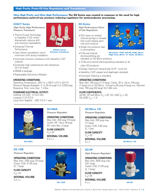
•Thermo-Fused Technology to Hastelloy C-22®which dramatically reduces driftand improves repeatability. •Enhanced ThermalPerformance. •Case Stress cancellation which minimizes shift during installation.•Improved corrosion resistance with Hastelloy C-22®material.•Extremely high overpressure ratio tolerances (3x Full Scale). •NEMA 4 package.•Replaceable Electronics Module.SQ SeriesHigh Performance Point-of-Use Regulators SQ Micro 130Pressure Regulator SQ 60SAPressure Regulator •SQ’s have no wetted internal springs or threads that could release parti-cles and moisture.•Single low pressure seal to atmosphere.•5 Ra and internalelectropolishing arestandard on SQ Micro products.•10 Ra and internal electropolishing standard on all other SQ products.•Design maximum inboard leak 2x10⁻¹⁰scc/s He.•Hastelloy C-22®poppet and diaphragm standard.•Hurricane Cleaning is standard.SQ Series: 140E, SQ HP , 420E, Micro High Flow, Micro “A ”Style, 60,MicroOPERATING CONDITIONS: Max Inlet: 250 psig (70 barg) Outlet: 28” Hg to 30 psig (67 mbar Abs .2 barg)FLOW CAPACITY:C v =.20INTERNAL VOLUME:5.2 c.c.OPERATING CONDITIONS Max Inlet: 250 psig max (17 barg)Outlet: 0-30, 0-60 psig (2, 7 bar)FLOW CAPACITY C v =.20INTERNAL VOLUME 5 c.c.OPERATING CONDITIONS:Max Inlet: 250 psig (17.2 barg), Outlet: 20 in. Hg to 100 psig(7 barg) not on SQ Micro - limited to 60 psig (4 barg) out, Optional Inlet: 750 psig (52 barg) SQ 140E onlyFLOW COEFFICIENTS:SQ 60, HP and Micro C v =.05, SQ 140E C v =.25,SQ 420E C v = 1.5Ultra High Purity and Ultra High Performance The SQ Series was created in response to the need for high performance point-of-use pressure reducing regulators for semiconductor processing.SQ Micro 130SQ 60SASQ HPHigh Pressure Regulator SQ 130EPressure RegulatorOPERATING CONDITIONS Max Inlet: 1000 psig (70 barg) Outlet: 0-30, 0-100 psig (2, 7 barg)FLOW CAPACITY C v =.22INTERNAL VOLUME 5.2 c.c.OPERATING CONDITIONS Max Inlet: 3500 psig max (241 barg)Outlet: 0-30, 0-100 psig (2, 7 barg)FLOW CAPACITY C v =.05INTERNAL VOLUME 5 c.c.SQ HPSQ 130EEXACT SeriesPressure Transducer EXACT SeriesHigh Purity High Performance Pressure TransducerOPERATING CONDITIONS:Operating Temperature: -20ºC to +105ºC (-4°F to 221°F),Pressure Ranges Available: 0 to 30 through 0 to 3,000 psig,Response Time: Less than 1 mSec STANDARD ELECTRICAL OUTPUT: 4-20mA, 0-5 VDC, .5-10.5 VDC Linearity 0 10-8 F .S.O.Long Term Stability - 250˚ F .S.O 1 yearVeriflo’s line of high purity valves provide the ultimate in performance for a unlimited variety of applications.955 SeriesHigh Flow Diaphragm Valves 944 SeriesDiaphragm ValvesOPERATING CONDITIONS:FLOW CAPACITY LEAKAGE:944 (L, LL, S, I, M): Vacuum to 3500 psig (241 barg)944 LL: C v =.18944 L or M: C v =.18 Inboard 2x10⁻¹⁰scc/s He 944 AOP LP: Vacuum to 125 psig (8.6 barg)944 S or G: C v =.25944 I: C v =.25944 AOP HP: Vacuum to 3500 psig (241 barg)944 AOP LP: C v =.25944 AOP HP: C v =.25INTERNAL VOLUME:944G: Vacuum to 125 psig (241 barg)3.36 c.c944 LL, 944 I,944 S, 944 L955 AOP NC, 955 I,955 AOP LP NO, 944G955 YOPERATING CONDITIONS:955 AOP LP: Vacuum to 125 psig (8.6 barg)955 S, G or I: Vacuum to 250 psig (17.2 barg)FLOW CAPACITY: C v =.55 (except 955L = .32)LEAKAGE: Inboard 2x10⁻¹⁰scc/s He INTERNAL VOLUME: 3.29 c.c.955 Y SeriesHigh Flow Manifold Valves OPERATING CONDITIONS: Vacuum to 125 psig (8.6 barg)LEAKAGE: Inboard: 2x10⁻¹⁰scc/s HeFLOW CAPACITY: Process Valve C v =.43, Purge Valve C v =.35944 AOP LP NO, 944 AOP HP , 944 AOP LP NC,•Fully field serviceable seat without special tools.•Available in a variety of multi-port configurations and connections - see Valve Selection Guide.•Internally threadless and springless.•Fully functional under all vacuum conditions.•5 Ra and internal electropolishing is standard.•Available in a variety of multi-port configurations and connections - see Valve Selection Guide.•5 Ra and internal electropolishing is standard.•Ideal for valve manifold boxes (vmb) and high flow OEM gas lines.•Large C v ideal for low vapor pressure gases.• Available with a variety of flow paths.OPERATING CONDITIONS:Vacuum to 125 psig (8.6 barg)LEAKAGE:Inboard: 2x10⁻¹⁰scc/s He.FLOW CAPACITY:Process Valve C v =.25, Purge Valve C v =.17Series SPR 860Servo Operated Pressure Regulator The Servo-Operated Series Regulators: Servo driven regulators are self adjusting and can achieve flows of up to2500 lpm and with negligible droop (1-2 psig).SQ ServoHigh Flow High Purity Servo Regulator Left: SPR 860 Right: SQ ServoOPERATING CONDITIONS:Maximum supply pressure: 750 psig (52 barg)LEAKAGE:Inboard: 2x10⁻¹⁰scc/s He.OPERATING CONDITIONS:LEAKAGE:Inlet: SPR 860 V: 500 psig (35 barg)Inboard: 2x10⁻⁹scc/s He.SPR 860 K: 200 psig (14 barg)Outlet: 1-30, 2-100 psig (2, 7 barg)945High Purity Valves945945YHigh Purity Valves 945YFLOW CAPACITY:945 L: C v = .18945 S, I, AOP , 945Y: C v = .25935 Series1/2” Facility ValveOPERATING CONDITIONS: Vacuum to 300 psig (20.7 barg) FLOW CAPACITY:C v = 2.8 (orifice size =0.5 in)LEAKAGE:Inboard 2x10⁻¹⁰scc/s He INTERNAL VOLUME: 16.2 c.c.Back: 935 Y , 935 T Front: 935, 935 / 917 L917917 SeriesHigh Purity Diaphragm Valve •Low internal volume.•Fully functional under all vacuum conditions.•Air operated valves are fully functional from a vacuum to 250 psig. •Fixed male gland-to-gland dimensions available (2.3").• 100% helium leak tested.• 1/8” connection option.•Internally threadless and springless.•Fully functional from vacuum to 300 psig.•Available up to 1” Tube Stubs.• 935/917 has a valve isolated purge or test port.•Ideal for valve manifold boxes (vmb) and high flow OEM gas lines •Available with a variety of flow path options•Low internal volume, 1.27 c.c.•Machined on tube stubs or fixed male face seal available.•Field serviceable.•5 Ra and internal electropolishing is standard.•Hurricane cleaning is standard.•For extremely high flows with a low pressure differential.•Does not require an external source to operate nor a continuous bleed to atmosphere.•Requires an external. source to operate •No internal springs •Facilities regulatorOPERATING CONDITIONS:917 (L, M, I and S): Vacuum to 3000 psig (207 barg)917 AOP: Vacuum to 250 psig (17.2 barg)Vacuum to 500 psig (34.5 barg)(using 955 Actuator)FLOW CAPACITY:917 L: C v = .15917 AOP:C v = .17917 I: C v = .17917 S: C v = .17LEAKAGE:Inboard 2x10⁻¹⁰scc/s He.959 TDR735 TDRTwo-Stage Tied Diaphragm Regulator 959 TDRTied Diaphragm RegulatorOPERATING CONDITIONS:Inlet: 3500 psig (241 barg)Outlet: 0-30, 0-100 psig (2, 7 barg)FLOW CAPACITY:C v =.04INTERNAL VOLUME: 7.3 c.c.OPERATING CONDITIONS:Inlet:3500 psig(241 barg) Outlet: 0-30, 0-100 psig (2, 7 barg)FLOW CAPACITY:C v =.04INTERNAL VOLUME:4.0 c.c.OPERATING CONDITIONS:Inlet: 3500 psig(241 barg) maximumOutlet: 0-20 in Hg to 30 psig (0-2 barg)NPR 959Negative Pressure Regulator QR SeriesNon-Tied Diaphragm Regulator OPERATING CONDITIONS:Inlet:4000 psig(276 barg) Outlet: 1-10,1-30, 2-60, 2-100,3-250(.7,2,4,7 ,17 barg),FLOW CAPACITY: (Typical) C v = .09(Gas C v Per ANSI/ISA S 75.02 1988)INTERNAL VOLUME:4.0 cc or 6.19 cc with fittingsQR SeriesNPR 400Negative Pressure Regulator OPERATING CONDITIONSInlet: 150 psig (10 barg)Outlet: 2 psig (.1 barg)•No high pressure seals to atmosphere.•Metal-to-metal diaphragm seal assures high leak integrity.•No high pressure seals to atmosphere.•Metal-to-metal diaphragm seal assures high leak integrity.•Adjustment range spring may be replaced without breaking the diaphragm seal to the body and exposing the wetted area to contamination.•Suitable for corrosive and non-corrosive gases.•Tall spring for excellent sensitivity.NPR 400NPR 959•Designed to minimize supply pressure effect.•Adjustment range spring may be replaced without breaking the diaphragm seal to the body and exposing the wetted area to contamination.•Metal-to-metal diaphragm-to-body seal assures high leak integrity•Capable of operating at negative pressures of up to 20 in. Hg.•Threadless.735 TDRIR 400Pressure Regulator HPR 800High Pressure Regulator DIR 600Two-Stage Regulator Brass IR 400HFR 900OPERATING CONDITIONS:Inlet: 4000 psig (275 barg)Outlet: 3-30, 2-100, 5-300, 10-500 psig(2, 7, 21, 34 barg)BODY:Brass Bar stock FLOW CAPACITY: C v =.02OPERATING CONDITIONS Inlet: 5000 psig (344 barg) at 70°F (21°C)Outlet: 10-800, 20-1500, 50-2500 psig, (55, 103, 172 barg)FLOW CAPACITY:C v =.02LEAKAGE:Inboard: 2x10⁻⁹scc/s HeHFR 900High Flow Pressure Regulator DSG 750Two-Stage Regulator Stainless SteelOPERATING CONDITIONS:Inlet: 500 psig (35 barg)Inlet: 200 psig (14 barg)Outlet: 1-30, 2-75, 5-150 psig (2, 5, 10 barg)HIR 2000High Purity Regulator OPERATING CONDITIONS:Inlet: 3500 psig (241 barg)Outlet:0-30 psig (0-2 barg),0-60 psig (0-4 barg),0-100 psig (0-7 barg)FLOW CAPACITY: C v =0.02LEAKAGE:Inboard: 1x10⁻⁹scc/s He INTERNAL VOLUME:13.8 c.c.OPERATING CONDITIONS: FLOW CAPACITY: C v =.02Inlet: 3000 psig (207 barg)Outlet: 1-15, 2-75, 5-150 psig (1, 5, 10 barg)LEAKAGE: Inboard: 2x10⁻⁹scc/s HeHIR 100Pressure RegulatorOPERATING CONDITIONS: Inlet: 3000 psig (207 barg)Outlet: 1-15, 1-30, 2-75, 5-150 psig (1, 2, 5, 10 barg)FLOW CAPACITY: C v =.13LEAKAGE:Inboard: 2x10⁻⁹scc/s He INTERNAL VOLUME:9.30 c.c.FLOW CAPACITY:LEAKAGE:C v =.85Inboard: 2x10⁻⁹scc/s HeINTERNAL VOLUME: 38 c.c.HIR 100HPR 800DIR 600HIR 2000DSG 750OPERATING CONDITIONS: Inlet:3000 psig (207 barg)Outlet:1-15, 2-75, 5-150 psig (1, 5, 10 barg)FLOW CAPACITY:C v =.13LEAKAGE:Inboard: 2x10⁻⁹scc/s He•High flow, mid purity regulator.•Large diaphragm area for minimal pressure drop.•Suitable for corrosive service and non-corrosive gases.•Low actuating torque •Diaphragm sensing regulator •Designed to reduce supply pressure effect •Large diaphragm area provides excellent flow curves.•Minimizes supply pressure effect •Large diaphragm area provides excellent flow curves for corrosive and non-corrosive gases •Fully field service availablefpo - High Res. Scan on file at LCP。
多回转电动装置使用说明书
1.概述多回转阀门电动装置,简称为Z型电装,是阀门实现开启、关闭或调节控制的驱动设备。
Z型电装适用于闸阀、截止阀、隔膜阀、柱塞阀、节流阀、水闸门等。
可用于明杆阀,也可用于暗杆阀。
本系列电装具有功能全、性能可靠、控制系统先进、体积小、重量轻、使用维护方便等特点。
可对阀门实行远控、集控和自动控制。
广泛用于电力、冶金、石油、化工、造纸、污水处理等行业。
本产品的性能符合JB/T8528-1997《普通型阀门电动装置技术条件》的规定。
隔爆型的性能符合GB3836.1-2000《爆炸性气体环境用电气设备第1部分:通用要求》,GB3836.2-2000《爆炸性气体环境用电气设备第2部分:隔爆型“d”》及JB/T8529-1997《隔爆型阀门电动装置技术条件》的规定。
多回转电动装置按防护类型分:有户外型和隔爆型;按控制方式分:有常规型、整体型和整体调节型;按连接型式分:有转矩型、电站型和推力型。
2.型号表示方法DZ —/A:带现场按钮;F:带4-20mA信号输出;S:带手动减速箱输出轴最大转圈数:阿拉伯数字表示,无数字见表1输出转速:阿拉伯数字表示,单位r/min(转/分)连接型式:T表示推力型,I表示电站型,无代号为常规转矩型额定输出转矩:阿拉伯数字表示,单位kgf·mZ:整体型;TZ:整体调节型防护类型:W表示户外型;B表示隔爆型产品型式:多回转电动装置型号示例:1.DZW30I-18/50:多回转电动装置,输出转矩300N·m(30kgf·m),电站型接口,输出转速18r/min,最大转圈数50,常规户外型。
2.DZBTZ45T-24B/S:多回转电动装置,输出转矩450N·m(45kgf·m),推力型接口,输出转速24 r/min,最大转圈数120,整体调节隔爆型,带手动减速箱。
3.DZZ120-24/240:多回转电动装置,输出转矩1200N·m (120kgf·m),转矩型接口,输出转速24 r/min,最大转圈数240圈,整体型。
AI-37028 37048 人工智能温度控制器 工业调节器 产品说明书

AI-37028/37048人工智能温度控制器/工业调节器产品说明书AI-3700系列人工智能温度控制器/工业调节器 AI-37028/37048目 录1、产品概述 ..................................................................... - 1 -2、主要技术指标 ................................................................. - 2 -2.1、仪表尺寸 ............................................................. - 2 -2.2、显示功能 ............................................................. - 2 -2.3、存储功能 ............................................................. - 2 -2.4、仪表输入 ............................................................. - 2 -2.5、仪表输出 ............................................................. - 2 -2.6、通讯功能 ............................................................. - 2 -2.7、控制功能 ............................................................. - 3 -2.8、综合参数 ............................................................. - 3 -3、仪表型号定义及模块使用 ....................................................... - 3 -3.1、型号定义 ............................................................. - 3 -3.2、模块使用 ............................................................. - 4 -4、仪表安装 ..................................................................... - 5 -4.1、产品外观 ............................................................. - 5 -4.2、安装尺寸图 ........................................................... - 5 -4.3、挂钩安装示意图 ....................................................... - 5 -5、仪表接线 ..................................................................... - 6 -5.1、接口形式 ............................................................. - 6 -5.2、接线方式 ............................................................. - 6 -5.3、电源接线 ............................................................. - 6 -5.4、通讯接线 ............................................................. - 6 -5.5、输入输出接线 ......................................................... - 6 -6、操作说明 ..................................................................... - 7 -6.1、首次操作说明 ......................................................... - 7 -6.2、显示画面界面操作说明 ................................................. - 8 -6.3、操作画面界面操作说明 ................................................. - 9 -6.4、实时趋势界面操作说明 ................................................ - 10 -6.5、历史趋势界面操作说明 ................................................ - 11 -6.6、数据报表界面操作说明 ................................................ - 12 -6.7、报警信息界面操作说明 ................................................ - 14 -6.8、系统设置界面操作说明 ................................................ - 15 -7、 扩展应用 ................................................................... - 18 -7.1、扩展说明 ............................................................ - 18 -7.2、工程组态 ............................................................ - 18 -7.3、工程下载 ............................................................ - 18 -8、附录 ........................................................................ - 19 -8.1、系统参数说明 ........................................................ - 19 -8.2、自整定操作 .......................................................... - 21 -8.3、以太网访问 .......................................................... - 21 -● 在使用本产品前,请仔细阅读此说明书,正确使用,并妥善保管,以便随时参考。
THK 滚针凸轮导向器
表1 静态安全系数(fS、 fM) 负荷条件 普通负荷 冲击负荷 fS和fM的下限 1~2 2~3
滚针凸轮导向器
【额定寿命】
滚针凸轮导向器的使用寿命可由下式计算。
L=
L
fT • C fW • PC
10 3
10
6
∶额定寿命 (一批相同的滚针凸轮导向器在相同条件下分别运动时,其中的90%不因滚动疲劳产生表面 剥落所能到达的总转数。 )
A
特长与类型
滚针凸轮导向器的特长
带内六角孔的滚针凸轮导向器
对于滚针凸轮导向器CF型、 内装止推钢球的滚针凸轮导向器CFN型以及偏心滚针凸轮导向器CFH型,提供 易于进行偏心调整的带内六角孔的螺柱。 如果要求在螺柱头上加工内六角孔,则请在公称型号的末尾加上A; 如果要求在螺柱的螺纹处加工内六 角孔,则加上B (B适用于CF12型或其以上的型号) 。
A
B 辅助手册(别册)
宇电AI V7.0人工智能工业调节器使用说明书

1
1 概叙
1.1 主要特点
●输入采用数字校正系统,内置常用热电偶和热电阻非线性校正表格,测量精度高达0.2级。 ●采用先进的AI人工智能调节算法,无超调,具备自整定(AT)功能。 ●采用先进的模块化结构,提供丰富的输出规格,能广泛满足各种应用场合的需要,交货迅速且维护方便。 ●人性化设计的操作方法,易学易用。 ●全球通用的100~240VAC输入范围开关电源或24VDC电源供电,并具备多种外型尺寸供客户选择。 ●通过新的2000版ISO9001质量认证,品质可靠。 ●产品经第三方权威机构检测获得CE认证标志,抗干扰性能符合在严酷工业条件下电磁兼容(EMC)的要求。
2
1.2 型号定义
AI系列仪表硬件采用了先进的模块化设计,具备5个功能模块插座:辅助输入、主输出、报警、辅助输出及通 讯。模块可以与仪表一起购买也可以分别购买,自由组合。仪表的输入方式可自由设置为常用各种热电偶、热电阻和 线性电压(电流)。AI系列人工智能调节仪表共由8部分组成,例如:
AI-808 A N X3 L5 N S4 — 24VDC
4
X5 自带隔离电源的光电隔离型线性电流输出模块,支持0~20mA及4~20mA输出,不占用仪表内部12VDC电源 W1 可控硅无触点常开式开关输出模块,容量为100~240VAC/0.2A,具备“烧不坏”特点 W2 可控硅无触点常闭式开关输出模块,容量为100~240VAC/0.2A,具备“烧不坏”特点 G 固态继电器(SSR)电压输出模块,规格为12VDC/30mA ⑤表示仪表报警(ALM)安装的模块(用于仪表AL1及AL2报警输出) L1/L2/L4 单路继电器输出模块,可支持AL1一路报警 L5 双路继电器常开触点输出模块,支持AL1及AL2二路报警 ⑥表示仪表辅助输出(AUX)安装的模块(用于仪表AU1、AU2报警或调节辅助输出) L1/L2/L4 单路继电器输出模块,可支持AU1一路报警或作为加热/冷却输出的辅助输出 L5 双路继电器常开触点输出模块,支持AU1及AU2二路报警 G 固态继电器(SSR)电压输出模块,规格为12VDC/30mA W1 可控硅无触点常开式开关输出模块,容量为100~240VAC/0.2A,具备“烧不坏”特点 K1 “烧不坏”单路可控硅过零触发输出模块,可触发5~500A双向或二个反并联的单向可控硅 X3 光电隔离型线性电流输出模块,支持0~20mA及4~20mA输出,占用仪表内部12VDC电源 X5 自带隔离电源的光电隔离型线性电流输出模块,支持0~20mA及4~20mA输出,不占用仪表内部12VDC电源 R 光电隔离的RS232C通讯接口,使用仪表内部12VDC电源 ⑦表示仪表通讯(COMM)安装的模块 X3 光电隔离型线性电流输出模块,支持变送输出,占用仪表内部12VDC电源 X5 自带隔离电源的光电隔离型线性电流输出模块,支持变送输出,不占用仪表内部12VDC电源 S 光电隔离的RS485通讯模块,使用仪表内部12VDC电源
- 1、下载文档前请自行甄别文档内容的完整性,平台不提供额外的编辑、内容补充、找答案等附加服务。
- 2、"仅部分预览"的文档,不可在线预览部分如存在完整性等问题,可反馈申请退款(可完整预览的文档不适用该条件!)。
- 3、如文档侵犯您的权益,请联系客服反馈,我们会尽快为您处理(人工客服工作时间:9:00-18:30)。
2
尺寸布局
CH01
CH02
A1
A1
A2
A2
OUT
OUT
CH03
CH04
A1
A1
A2
A2
OUT
OUT
CH05
CH06
A1
A1
A2
A2
OUT
OUT
CH SET
EXIT
THKA多路智能工业调节器
测量值显示或参数代号 测量值显示或内部参数值
上限报警指示灯 下限报警指示灯 主控输出指示灯 温度控制设定键 内部叁数设定键 移位键 减数键 加数键 退出并保存设置
输入信号
热电偶: K、S、E、J、T、B、N、R、WRe3-25、WRe5-26、F2(辐射传感器) 热电阻: PT100、CU50、CU100 电 流: 0~20mA、4~20mA 电 压: 0~5V、1~5V、0~10V 毫 伏: 0-100mV、0-75mV、0-50mV、0-60mV 电 阻: 0-400欧(用于远传压力表)
96(W)
95mm
92(W)
面板尺寸
开孔尺寸
96(H) 96(H) 92(H)
3
背面输入部份共有2组可插拔的端子,每组为3个输入通道,最大为6路信号输入,可 连 接 热 电 偶,热 电 阻, 4 ~ 2 0 m A , 0 ~ 5 V, 0 ~ 1 0 V , 1 ~ 5 V, 0 ~ 7 5 m V, 0 ~ 1 0 0 m V等 多 种 传感器,实现温度,压力,湿度的信号采集。
CH03
CH04
A1
A1
A2
A2
OUT
OUT
两路温控面板
PV CH01
PV CH02
SV SV
A1 A2 OUT A1 A2 OUT
CH
SET
EXIT
THKA多路智能工业调节器
每路独立上下限报警指示灯 两个公共报警继电器触发输出 每路一个独立PID控制 同时显示4路测量值
CH SET
EXIT
THKA多路智能工业调节器
六路温控面板
CH01
CH02
A1
A1
A2
A2
OUT
OUT
CH03
CH04
A1
A1
A2
A2
OUT
OUT
CH05
CH06
A1
A1
A2
A2
OUT
OUT
CH SET
EXIT
THKA多路智能工业调节器
每路独立上下限报警指示灯 两个公共报警继电器触发输出 每路一个独立PID控制 同时显示6路测量值
三路温控面板
电 脑 通讯 24 V馈 电 2 4 V馈 电 下限 报 警 上 限 报 警
仪表供电
LN
-485+ -P1+ -P2+ -A2+ -A1+ 控制1 控制2 控制3 控制4 控制5
Power 控制6
+ D 1 - + D 2 - + D 3 - + D 4- -+ D 5 +- + D 6 -
1-6通道控制输出
通讯接口
通讯输出: RS485通讯 标准MODBUS RTU通讯协议
技术指标
采样精度: 0.2FS%(优于全量程的0.2%) 温度量程: -200.0~2400.0℃ 湿度量程: 0~100%RH 标准信号: -20000~+20000(4~20mA,0~10V) 采样速度: 1秒采样所有通道(最大6通道)。 控制输出: 6路PID调节或报警输出(用户自定义输出) 电磁兼容: 电磁兼容:IEC61000-4-4(电快速瞬变脉冲群) 报警输出: 上限报警与下限报警两组公共报警输出
THKA多回路智能工业调节器
①工业阻燃外壳
⑥可电脑监控送软件
②万能信号输入
⑤高性能模块电源
③PID控制与自整定
④公共上下限报警输出
①注重每个细节,精心设计的模具外壳,更符合产品特性 ②支持4-20mA,0-5V,0-10V 热电偶 热电阻万能输入,温度 湿度 压力均适用 ③高精度的PID控制,4-20mA 0-10V 0-5V输出可选 ④可独立设定每个通道的上下限报警,并具备两个公共触点输出,接线更方便 ⑤模块化的密封电源,更加稳定靠,搭载一个24V馈电输出,更加稳定,可靠 ⑥当选择带通讯485接口时,可免费使用我们的通讯软件,一台电脑150台仪表组网
1
产品选型
①②③
THK A
③
输出接口不需要时可空,表示不支持任何接口,接口只能选一个
K: RS485通讯接口,Modbus RTU协议
主控输出
0: 2个开关量(上下限公共报警输出) 1: 每路1个开关量输出+2个开关量公共报警
②
7: 每路1个SSR输出+2个开关量公共报警 8: 每路1个4-20mA输出+2个开关量公共报警
每路独立上下限报警指示灯 两个公共报警继电器触发输出 每路一个独立PID控制 同时显示2路测量值与两路设定值
产品简介
采 用 万 能 信 号 输 入,可 用 于 电 流,电 压,温 度,液 位,湿 共 报 警 输 出,最 多 可 选 配6个P I D控 制 输 出,用 于P I D控 制 或变送输出。
1-3通道输入
CH01 CH02 CH03
4-6通道输入
CH04 CH05 CH06
BCG BCG BCG
BCG BCG BCG
仪表默认供电交流或直流110~220V 控制输出D1-D6分别对应1-6路输出 CH01-CH06分别对应1-6路输入 每个输入信号有三个接线端子B,C,G 接线端子可拔下,接好线后插在仪表上 标配DC24V馈电输出
G
热电阻接线
BCG
PT100、CU50、CU100属于电阻式温度传感器,
B连 接 电 阻 独 立 引 线 端 , 仪 表C,G端 子 分 别 连 接 电 阻
R
约 为 零 的 两 端,通 常 与C、G相 连 的 两 根 线 端 子 颜 色 是
CH01 CH02 CH03
PV
SV
A1
A2
OUT
PV
SV
A1
A2
OUT
PV
SV
A1
A2
OUT
CH
SET
EXIT
THKA多路智能工业调节器
每路独立上下限报警指示灯 两个公共报警继电器触发输出 每路一个独立PID控制 同时显示3路测量值与3路设定值
四路温控面板
CH01
CH02
A1
A1
A2
A2
OUT
OUT
通道选择
02 两路万能信号输入
① 03 三路万能信号输入
04 四路万能信号输入 06 六路万能信号输入
输出资源
每通道可定义上下限报警、PID调节或变送输出,仪表标配2个报警 继电器输出,另外6组输出根据要求选配。
材质指标
仪表壳体: 工业级阻燃外壳 环境温度: -10~50℃(仪器环境) 环境湿度: 0~85%RH相对湿度 仪表尺寸: 96MM(宽)X96mm(高)X95MM(深). 开孔尺寸: 92MM(宽)X92mm(高)
