ESCHA德国艾查接插件、总线、工业以太网、电磁阀连接器等中文样本
美国爱本斯公司高压地下电缆终端设备的CA650003EN版产品说明说明书
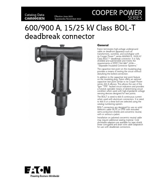
GeneralEaton terminates high-voltage underground cable on deadfront apparatus such astransformers, switches, and switchgear with its Cooper Power E series 600/900 A, 15/25 kV Class BOL -T E deadbreak connector. It is fully shielded and submersible and meets the requirements of IEEE T Std 386E -2016—“Separable Insulated Connector Systems.”The capacitive test point on the insulating plug provides a means of testing the circuit without disturbing the bolted connection.In addition to the capacitive test point feature on the insulating plug, Eaton offers an optional capacitive test point similar to its Cooper Power series 200 A elbows. This allows the use of the Type “TPR” faulted circuit indicators and provides a hotstick operable means of determining circuit condition when used with high-impedance voltage sensing devices designed for test points.The BOL -T is rated to 600 A continuous current when used with aluminum connectors. It is rated to 900 A or a shear bolt are selected using the catalog numbering system.BOL -T connectors are designed for use on solid dielectric cable (XLPE or EPR) with extruded semi-conductive shields and concentric neutral, with or without a jacket.Installation on jacketed concentric neutral cable may require additional sealing material. Cold shrinkable adapters are available for tape shield, linear corrugated and drain wire cable adaptation for use with deadbreak connectors.600/900 A, 15/25 kV Class BOL-Tdeadbreak connector2Catalog Data CA650003ENEffective June 2023600/900 A, 15/25 kV Class BOL -Tdeadbreak connectorEATON 900 A ratingThe BOL -T connector is rated for 900 A continuous when used with a coppertop compression connector or shear bolt, copper insulating plug, copper stud, and copper bushing or junction. If a 900 A rating is desired, specify a “C ” as the 10th digit when determining the part number. See Step 3 on page 5.InterchangeabilityEaton’s Cooper Power series 600 A deadbreak connectors conform to the electrical, mechanical, and dimensional requirements ofIEEE Std 386-2016. The connectors can be used on any comparably rated bushing interface that also meets the requirements of this standard. In addition, all cable adapters, insulating plugs,compression connectors, and other component parts are designed to be interchangeable with those currently available from other major manufacturers that also comply with IEEE Std 386-2016.InstallationA torque wrench and 1-inch socket are used to tighten theinsulating plug through the compression or shear bolt connector within the T -body onto a de-energized 600 A bushing interface. Refer to Service Information MN650005EN 600 A 15/25 kV Class BOL -T and Separable Splice Connector Assembly Installation Instructions for details.Production testsTests conducted in accordance with IEEE Std 386-2016:•ac 60 Hz 1-minute withstand • 40 kV•Minimum partial discharge extinction voltage • 19 kVTests conducted in accordance with Eaton re q uire m ents:• Physical in s pec t ion • Periodic dissection •Periodic X-ray analysisT able 1. Voltage ratings and characteristicsDescriptionkVStandard voltage class25Maximum rating phase-to-ground 15.2ac 60 Hz 1-minute withstand 40dc 15-minute withstand 78BIL and full wave crest125Minimum partial discharge extinction voltage 19ote: N Voltage ratings and characteristics are in accordance with IEEE Std 386-2016.T able 2. Current ratings and characteristicsDescriptionAmperesContinuous 600 A rms (aluminum)900 A rms (copper or shear bolt)4-hour overload900 A rms (aluminum)1200 A rms (copper or shear bolt)Short time (aluminum)40,000 A rms symmetrical for 0.17 s 27,000 A rms symmetrical for 4 s Short time(copper or shear bolt)40,000 A rms symmetrical for 0.17 s 27,000 A rms symmetrical for 4 sote: N Current ratings and characteristics are in ac c or d ance with IEEE Std 386-2016.3Catalog Data CA650003ENEffective June 2023600/900 A, 15/25 kV Class BOL -T deadbreak connector EATON Features and benefitsFigure 1. BOL -T cutaway design featuresote: N Dimensions are in inches (mm) and are for reference only.4Catalog Data CA650003ENEffective June 2023600/900 A, 15/25 kV Class BOL -Tdeadbreak connectorEATON Optional featuresCoppertop compression connectorsCoppertop compression connectors (aluminum sleeve welded toa copper spade) provide a high-conductivity material in a boltedconnection and are compatible with aluminum or copper conductors.Shear bolt connectorsBolted cable lug is fitted with stepless bolts, which shear offwhen optimum contact force has been reached. Provide electrical continuity for copper and aluminum conductors while eliminating need for dies and compression tools.Shear bolt connectorAll copper current pathA full copper current-carrying path can be obtained by specifying a coppertop compression connector, copper stud, and copperinsulating plug.Figure 2. BOL -T stacking dimensions in inches (mm)Ordering informationEach BOL -T connector kit contains:• Molded rubber T -body • Insulating plug • Insulating plug cap• Compression or shear bolt connector • Cable adapter • Silicone lubricant•Installation instruction sheetTo order a 15/25 kV Class BOL -T connector kit, see following Steps 1–5 to build the catalog number.BOL -T connector kit—catalog numbering systemBuild the 12-digit catalog number for a BOL -T kit by following the steps given below. The first 5 digits are “BT625”, so only digits 6 through 12 need to be selected.123456789101112BT625Catalog number digits:1 and2 — “BT ” = BOL -T connector system3 — “6” = 600 A system4 and5 — “25” = 25 kV class bushing interfaceStep 1. Select digits 6 and 7 cable adapter range code Determine the cable’s diameter over the electrical insulation as shown in Figure 3 (including tolerances).Then identify a cable range from T able 3 that covers the minimum and maximum insulation diameters.Select the correct cable adapter range code from T able 3.T able 3. Cable diameter rangeInchesmmCable adapter range code0.61–0.9715.5–24.6AB 0.75–1.0819.1–27.4CC 0.97–1.3124.6–33.3DD 1.09–1.4727.7–37.3EE 1.26–1.6432.0–41.7FF 1.36–1.7134.5–43.4GG 1.51–1.8538.4–47.0HH 1.70–1.9743.2–50.0JJ5Catalog Data CA650003ENEffective June 2023600/900 A, 15/25 kV Class BOL -T deadbreak connector EATON Step 2. Select digits 8 and 9 conductor codeIdentify the conductor size and type in T able 4 (compression) or T able 5 (shear bolt) and select the conductor code from the appropriate column.T able 4. Compression connectorConcentric or compressed Compact or solid Conductor codeAWG or kcmilmm 2AWG or kcmilmm 2No connector 00#2351—11#1—1/050121/0502/070132/0703/0—143/0—4/095154/09525012016250120300—17300—350—18350—40018519400185450—20450—5002402150024060030022600300700—23650—750—24750—900—25900—1000500261000500——2712506301250—28T able 5. Shear bolt connectorCable conductor size Conductor code Catalognumber AWG or kcmilmm 2standard sizesCompact Compressed Concentric1/01/01/050S1CDT630SB1502/02/02/0703/03/03/0—4/04/04/095250250250120350——150—350350185S3CDT630SB300500500500240600600600300700————700700—S4CDT630SB400750750750—800800—400900—————800—S5CDT900SB500—900900—100010001000500Step 3. Select digit 10Determine whether aluminum or copper is required for the compression connector, stud, and deadbreak insulating plug. “A ” = Aluminum (shear bolt or compression connector)“C ” = Copper mating components (shear bolt or coppertopcompression connector) (required to achieve 900 A rating)Step 4. Select digit 11Determine if a stud should be included in the kit. “1” = Stud included “2” = Stud not included Step 5. Select digit 12 (optional)Determine if the T -body should have a test point.“T ” = Test point on T -bodyIf no test point is required, do not include a 12th digit.ExampleSelect a BOL -T kit for 250 kcmil compressed cable with a nominal insulation diameter of 1.160 ± 0.030 inches. The kit should have aluminum current-carrying parts and should have a stud included. The T -body should have a test point.Step 1. Select digits 6 and 7Nominal diameter over insulation is 1.160 ± 0.030 inches.Minimum diameter = 1.160 – 0.030 = 1.130 inches.Maximum diameter = 1.160 + 0.030 = 1.190 inches.From T able 3, identify the cable range that covers1.130–1.190 inches and select the “EE ” cable range code.Step2. Select digits 8 and 9The conductor size is 250 kcmil compressed. From T able 4, under the column “Concentric or compressed,” identify 250 kcmil and select the “17” conductor code.Step 3. Select digit 10The kit should have aluminum current-carrying parts. Select an “A ” for digit 10.Step 4. Select digit 11The kit should include a stud. Select “1” for digit 11.Step 5. Select digit 12A test point is needed. Use “T ” for digit 12.The complete catalog number is: BT625EE17A1T .6Catalog Data CA650003ENEffective June 2023600/900 A, 15/25 kV Class BOL -Tdeadbreak connectorEATON Figure 3. T ypical construction of medium-voltage underground cableAccessoriesCable adapters, compression connectors, and other accessories that can be used with BOL -T connectors are described in Catalog Data CA650007EN, “Deadbreak accessories, tools, and replacement parts.”T able 6. Replacement partsDescriptionCatalog numberT-body without test point DT625T-body with test pointDT625T T-body without test point with aluminum stud DT625SA T-body without test point with copper stud DT625SC T-body with test point with aluminum stud DT625TSA T-body with test point with copper stud DT625TSC Insulating plug capDIPCAP Aluminum insulating plug with cap (no stud)DIP625A Copper insulating plug with cap (no stud)DIP625C Aluminum insulating plug with cap and aluminum stud DIP625AS Copper insulating plug with cap and copper stud DIP625CS 5/8-inch—11 UNC 2 A aluminum threaded stud STUD-A 5/8-inch—11 UNC 2 A copper threaded stud STUD-C7Catalog Data CA650003ENEffective June 2023600/900 A, 15/25 kV Class BOL -T deadbreak connector EATON Eaton1000 Eaton Boulevard Cleveland, OH 44122United StatesEaton’s Power Systems Division 2300 Badger Drive Waukesha, WI 53188United States/cooperpowerseries© 2023 EatonAll Rights ReservedPrinted in USAPublication No. CA650003EN / Z27614 June 2023Eaton is a registered trademark.All other trademarks are propertyof their respective owners.600/900 A, 15/25 kV Class BOL-Tdeadbreak connectorCatalog Data CA650003EN Effective June 2023。
中文版AS_4777[1].
![中文版AS_4777[1].](https://img.taocdn.com/s3/m/ae5c0021192e45361066f57a.png)
3.4逆变器
使用半导体器件在直流电源或者负载和交流电源或者负载之间传输能量的装置。
说明:尽管本标准的编写基础为来自于直流电源(例如光电池阵)的再生能源,但是本标准可以用于来自于可变的交流电源系统(例如风力涡轮机或者微型水电系统)的能源,因此,在本标准中,使用半导体器件的交流变流器同样可以视为逆变器,因为本标准中的这些要求适用于这种系统。
通过监控配电网避免形成孤岛的方法。
3.9机电式开关
OFF状态导致导线物理分离(例如机械继电器)的电气开关。这不包括晶体管或者类似的半导体器件。
3.10不间断电源(UPS)系统
电源系统包含逆变器、开关、控制回路以及在配电网电源中断时用来保持负载电源连续性的一种蓄能设备。
4通用要求和安全要求
4.1概述
逆变器能源系统电网防护应当通过电网保护装置提供。这不排除电网保护装置作为逆变器整体一部分的情况,也不排除用来保护逆变器能源系统(包含多重逆变器)的单一电网保护装置。
(a)单相系统的Vmin应该在200-230V范围内,三相系统在350-400V范围内;
(b)单相系统的Vmax应该在230-270V范围内,三相系统在400-470V范围内;
(c)fmin应该在45-50 Hz范围内。
(d)fmax应该在50-55Hz范围内。
Vmax、Vmin、fmax和fmin范围可以预置或者可编程序。Vmax、Vmin、fmax和fmin值可以与相关电力分销商协商。电网保护装置的整定值不应超过逆变器的容量。
澳大利亚标准™
能源系统通过逆变器并网
第3部分电网保护要求
最初作为AS 4777.3—2002发布。
2005年再版
版权所有
© Standards Australia
1-1469491-2中文资料

1-1469491-2 Product DetailsHome | Customer Support | Suppliers | Site Map | Privacy Policy | Browser Support© 2008 Tyco Electronics Corporation All Rights Reserved SearchProducts Documentation Resources My Account Customer SupportHome > Products > By Type > Two-Piece, High-Speed Connectors > Product Feature Selector > Product Details1-1469491-2Active MULTIGIG RT ProductAlways EU RoHS/ELV Compliant (Statement of Compliance)Product Highlights:?Pin, External Thread?Guidance Series?VITA 41/VITA 46 Configuration?Used With 9mm Guide ModuleView all Features | Find SimilarProductsCheck Pricing &AvailabilitySearch for ToolingProduct FeatureSelectorContact Us AboutThis ProductQuick LinksDocumentation & Additional InformationProduct Drawings:?KEYED GUIDE PIN, DIE CAST BACKPLANE CONNECTOR, MULTI...(PDF, English)Catalog Pages/Data Sheets:?Power Connectors & Interconnection Systems Catalog -...(PDF, English)?MULTIGIG RT Connector Products for VITA 46 (VPX) Sta...(PDF, English)Product Specifications:?None AvailableApplication Specifications:?None AvailableInstruction Sheets:?None AvailableCAD Files:?None AvailableList all Documents Additional Information:?Product Line InformationRelated Products:?ToolingProduct Features (Please use the Product Drawing for all design activity)Product Type Features:?Product Type = Pin, External Thread ?Finish = Silver?Comment = KeyedBody Related Features:?Series = Guidance?Used With = 9mm Guide Module?Pin Material = Zinc Alloy Industry Standards:?RoHS/ELV Compliance = RoHS compliant, ELVcompliant?Lead Free Solder Processes = Not relevant forlead free process?VITA 41/VITA 46 Configuration = Yes?RoHS/ELV Compliance History = Always wasRoHS compliantOther:?Brand = AMPProvide Website Feedback | Contact Customer Support。
艾茨顿199034产品说明说明书

Eaton 199034Eaton Moeller® series Rapid Link - Speed controllers, 8.5 A, 4 kW, Sensor input 4, Actuator output 2, 230/277 V AC, PROFINET, HAN Q4/2, with braking resistance, with fanGeneral specificationsEaton Moeller® series Rapid Link Speed controller199034195 mm270 mm 220 mm 3.65 kgUL 61800-5-1 IEC/EN 61800-5-1 UL approval RoHS CERASP5-8422PNT-4120101S1Product NameCatalog NumberProduct Length/Depth Product Height Product Width Product Weight Certifications Catalog Notes Model Code3 fixed speeds and 1 potentiometer speedcan be switched over from U/f to (vector) speed control Connection of supply voltage via adapter cable on round or flexible busbar junction480 VIs the panel builder's responsibility. The specifications for the switchgear must be observed.400 V AC, 3-phase480 V AC, 3-phaseMeets the product standard's requirements.4 kW500 VMeets the product standard's requirements.-40 °C380 VThermo-click with safe isolationBraking resistance2 Actuator outputsIGBT inverterKey switch position AUTOPC connectionKey switch position HANDSelector switch (Positions: REV - OFF - FWD)FanKey switch position OFF/RESETPTC thermistor monitoringControl unitInternal DC linkBreaking resistanceTwo sensor inputs through M12 sockets (max. 150 mA) for quick stop and interlocked manual operation0 Hz Generation change from RA-SP to RASP 4.0Generation change RAMO4 to RAMO5Generation change from RA-MO to RAMO 4.0Configuration to Rockwell PLC for Rapid LinkGeneration Change RA-SP to RASP5Generation Change RASP4 to RASP5Rapid Link 5 - brochureDA-SW-USB Driver DX-COM-STICK3-KITDA-SW-USB Driver PC Cable DX-CBL-PC-1M5DA-SW-Driver DX-CBL-PC-3M0DA-SW-drivesConnect - installation helpDA-SW-drivesConnect - InstallationshilfeDA-SW-drivesConnectMaterial handling applications - airports, warehouses and intra-logistics ETN.RASP5-8422PNT-4120101S1.edzIL034093ZUramo5_v36.dwgrasp5_v36.stpDA-DC-00003964.pdfDA-DC-00004184.pdfDA-DC-00004514.pdfDA-DC-00004508.pdfeaton-bus-adapter-rapidlink-speed-controller-dimensions-002.eps eaton-bus-adapter-rapidlink-speed-controller-dimensions-003.eps eaton-bus-adapter-rapidlink-speed-controller-dimensions.epseaton-bus-adapter-rapidlink-speed-controller-dimensions-004.epsMains voltage - max10.11 Short-circuit ratingRated operational voltage10.4 Clearances and creepage distancesOutput at quadratic load at rated output voltage - max Output voltage - max10.2.3.1 Verification of thermal stability of enclosures Ambient storage temperature - minMains voltage - minFitted with:Output frequency - min Applikasjonsmerknader BrosjyrereCAD model Installeringsinstruksjoner mCAD model SertifiseringsrapporterTegningerStarting current - max200 %, IH, max. starting current (High Overload), For 2 seconds every 20 seconds, Power sectionRated conditional short-circuit current (Iq)10 kAAmbient operating temperature - max40 °CCommunication interfacePROFINET, optionalAssigned motor power at 115/120 V, 60 Hz, 1-phase5 HPOutput frequency - max500 HzSwitching frequency8 kHz, 4 - 32 kHz adjustable, fPWM, Power section, Main circuitFeaturesParameterization: drivesConnect mobile (App) Parameterization: FieldbusInternal and on heat sink, temperature-controlled Fan Parameterization: drivesConnectParameterization: KeypadAmbient operating temperature - min-10 °CBraking current≤ 0.6 A (max. 6 A for 120 ms), Actuator for external motor brakeNumber of HW-interfaces (serial TTY)10.6 Incorporation of switching devices and componentsDoes not apply, since the entire switchgear needs to be evaluated.Nominal output current I2N8.5 A10.2.6 Mechanical impactDoes not apply, since the entire switchgear needs to be evaluated.10.3 Degree of protection of assembliesDoes not apply, since the entire switchgear needs to be evaluated.Product categorySpeed controllerRadio interference classC2, C3: depending on the motor cable length, the connected load, and ambient conditions. External radio interference suppression filters (optional) may be necessary.C1: for conducted emissions onlyHeat dissipation capacity Pdiss0 WRated control voltage (Uc)230/277 V AC (external brake 50/60 Hz)24 V DC (-15 %/+20 %, external via AS-Interface® plug)Assigned motor power at 460/480 V, 60 Hz, 3-phase5 HPNumber of HW-interfaces (RS-422)Mains current distortion120 %ProtocolPROFINET IO10.9.2 Power-frequency electric strengthIs the panel builder's responsibility.Overvoltage categoryIIIDegree of protectionIP65NEMA 12Ambient storage temperature - max70 °CRated impulse withstand voltage (Uimp)2000 VConnectionPlug type: HAN Q4/2Overload currentFor 60 s every 600 sAt 40 °CFunctionsFor actuation of motors with mechanical brake3 fixed speeds1 potentiometer speedBrake chopper with braking resistance for dynamic braking4-quadrant operation possibleOutput at linear load at rated output voltage - max4 kWMains voltage tolerance380 - 480 V (-10 %/+10 %, at 50/60 Hz)Leakage current at ground IPE - max3.5 mAConverter typeU converter10.2.2 Corrosion resistanceMeets the product standard's requirements.Supply frequency50/60 Hz10.2.4 Resistance to ultra-violet (UV) radiationMeets the product standard's requirements.10.2.7 InscriptionsMeets the product standard's requirements.Shock resistance15 g, Mechanical, According to IEC/EN 60068-2-27, 11 ms, Half-sinusoidal shock 11 ms, 1000 shocks per shaftApplication in domestic and commercial area permittedYesNumber of inputs (analog)Number of phases (output)310.12 Electromagnetic compatibilityIs the panel builder's responsibility. The specifications for the switchgear must be observed.10.2.5 LiftingDoes not apply, since the entire switchgear needs to be evaluated.Number of HW-interfaces (RS-485)1Number of HW-interfaces (industrial ethernet)Efficiency98 % (η)System configuration typePhase-earthed AC supply systems are not permitted.AC voltageCenter-point earthed star network (TN-S network)10.8 Connections for external conductorsIs the panel builder's responsibility.Switch-on threshold for the braking transistor765 VDCProtectionFinger and back-of-hand proof, Protection against direct contact (BGV A3, VBG4)Braking voltage230/277 V AC -15 % / +10 %, Actuator for external motor brakeApplication in industrial area permittedYesClimatic proofingIn accordance with IEC/EN 50178< 95 %, no condensation10.9.3 Impulse withstand voltageIs the panel builder's responsibility.Overload current IL at 150% overload12.7 AInput current ILN at 150% overload7.8 ANumber of HW-interfaces (RS-232)Number of inputs (digital)4Current limitationAdjustable, motor, main circuit0.8 - 8.5 A, motor, main circuitCable lengthC3 ≤ 25 m, maximum motor cable lengthC1 ≤ 1 m, maximum motor cable lengthC2 ≤ 5 m, maximum motor cable length10.5 Protection against electric shockDoes not apply, since the entire switchgear needs to beevaluated.Mounting positionVerticalMains switch-on frequencyMaximum of one time every 60 seconds10.13 Mechanical functionThe device meets the requirements, provided the information in the instruction leaflet (IL) is observed.10.9.4 Testing of enclosures made of insulating materialIs the panel builder's responsibility.Heat dissipation per pole, current-dependent Pvid0 WElectromagnetic compatibility1st and 2nd environments (according to EN 61800-3)Resolution0.1 Hz (Frequency resolution, setpoint value)Assigned motor power at 460/480 V, 60 Hz5 HPRelative symmetric net voltage tolerance10 %Rated operational current (Ie)8.5 A at 150% overload (at an operating frequency of 8 kHz and an ambient air temperature of +40 °C)Number of outputs (analog)Rated operational power at 380/400 V, 50 Hz, 3-phase4 kWNumber of HW-interfaces (USB)Operating modeSensorless vector control (SLV)PM and LSPM motorsSynchronous reluctance motorsBLDC motorsU/f controlRated frequency - min45 HzDelay time< 10 ms, On-delay< 10 ms, Off-delayNumber of outputs (digital)2Power consumption95 W10.2.3.2 Verification of resistance of insulating materials to normal heatMeets the product standard's requirements.10.2.3.3 Resist. of insul. mat. to abnormal heat/fire by internal elect. effectsMeets the product standard's requirements.Number of HW-interfaces (other)Rated frequency - max66 HzVibrationResistance: According to IEC/EN 60068-2-6Resistance: 6 Hz, Amplitude 0.15 mmResistance: 10 - 150 Hz, Oscillation frequency Resistance: 57 Hz, Amplitude transition frequency on accelerationShort-circuit protection (external output circuits)Type 1 coordination via the power bus' feeder unit, Main circuit10.7 Internal electrical circuits and connectionsIs the panel builder's responsibility.Braking torque≤ 30 % (I/Ie)Adjustable to 100 % (I/Ie), DC - Main circuitRelative symmetric net frequency tolerance10 %10.10 Temperature riseThe panel builder is responsible for the temperature rise calculation. Eaton will provide heat dissipation data for the devices.Number of HW-interfaces (parallel)Assigned motor power at 230/240 V, 60 Hz, 1-phase5 HPInterfacesNumber of slave addresses: 31 (AS-Interface®)Eaton Corporation plc Eaton House30 Pembroke Road Dublin 4, Ireland © 2023 Eaton. Med enerett.Eaton is a registered trademark.All other trademarks are property of their respectiveowners./socialmediaMax. total power consumption from AS-Interface® power supply unit (30 V): 250 mASpecification: S-7.4 (AS-Interface®)351.6 W at 25% current and 0% speed 53.8 W at 25% current and 50% speed 60.9 W at 50% current and 0% speed 64 W at 50% current and 90% speed 65.4 W at 50% current and 50% speed 85.1 W at 100% current and 0% speed 94 W at 100% current and 50% speed 95.3 W at 100% current and 90% speed 2Max. 2000 mAbove 1000 m with 1 % performance reduction per 100 mNumber of phases (input)Heat dissipation at current/speed Number of interfaces (PROFINET)Altitude。
艾德克斯IT6302 用户手册

IEC 61000-4-11:2004。电压骤降和中断抗扰性 EN 61000-3-2:2006: 交流电源线谐波辐射 EN 61000-3-3:1995: 电压变化、波动和闪变
1 本产品仅在非居民区内使用,在居民区内使用可能造成电磁干扰。 2 当该设备与测试对象连接时,可能产生超过此标准要求的辐射级别。 3 为确保符合上面列出的 EMC 标准,应使用高质量的屏蔽接口电缆。 4 在 IEC 61000-4-3 测试条件下,可包括峰-峰值不超过 4 格的光迹噪声(Trace bloom) 。 5 在 IEC 61000-4-6 测试条件下,可包括峰-峰值不超过 1 格的光迹噪声(Trace bloom). 版权所有 © 艾德克斯电子有限公司 iii
“警告 ”标志表示有危险。它要求 在执行操作步骤时必须加以注意, 如果不正确地执行操作或不遵守 操作步骤, 则可能导致人身伤亡。 在没有完全理解指定的条件且不 满足这些条件的情况下,请勿继 续执行 “警告 ”标志所指示的任 何不当操作。
“说明”标志表示有提示,它要 求在执行操作步骤时需要参考, 给操作员提供窍门或信息补充。
IT6302 用户手册
6 性能标准 C 应用于 70%/25 周期电压跌落以及 0%/250 周期电压中断测试水平( IEC 61000-4-11) 。
版权所有 © 艾德克斯电子有限公司
iv
IT6302 用户手册
目录
认证与质量保证 .............................................................................................................................................................. 1 保固服务 .......................................................................................................................................................................... 1 保证限制 .......................................................................................................................................................................... 1 安全标志 .......................................................................................................................................................................... 1 安全注意事项 .................................................................................................................................................................. 2 环境条件 .......................................................................................................................................................................... 2 法规标记 .......................................................................................................................................................................... 3 废弃电子电器设备指令(WEEE) ................................................................................................................................. 3 符合性信息 ...................................................................................................................................................................... 3 第一章 验货与安装 ...................................................................................................................................................1
德国工业实际联系部件编号说明说明书

0460-256-12**
12 PIN
1.5 mm² 16 AWG 1.0 mm²
18 AWG 0.75 mm²
35 [156] 25 [111]
.222-.284 [5.64-7.21]
0460-215-16** 0462-209-16**
16 PIN 16 SOC
14 AWG 2.0 mm²
70 [311]
7 CYCLE TOOL TO OPEN HANDLES. REMOVE LOCK CLIP. RAISE AND ROTATE DIAL TO SELECT WIRE SIZE. REPLACE LOCK CLIP.
6 WHEN **= 31, PLATING IS GOLD. WHEN **=141, PLATING IS NICKEL.
3 USE 1.5 SETTING FOR THIS PART WITH 14 AWG.
2 CAUTION: NEVER CLOSE TOOL ON GAGE G454. CLOSE TOOL FIRST AND THEN INSERT GAGE.
1 USE GAGE G454 IN DCHECK WEAR ANNUALLY. CHECK
1.5 mm² 16 AWG 1.0 mm²
18 AWG 0.75 mm²
4.0 mm² 12 AWG 3.0 mm² 2.5 mm²
35 [156] 25 [111]
.222-.284 [5.64-7.21]
75 [334]
.222-.284 [5.64-7.21]
SLOTTED (SPLIT) PIN 11
NOTES: UNLESS OTHERWISE SPECIFIED
Acterna SDA-5000系列Stealth数字分析器的中文名字说明书
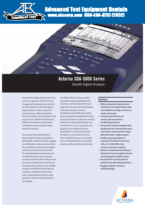
800-404-ATEC (2832) E s t a b l i s h e d1981Acterna SDA-5000 SeriesStealth Digital AnalyzerForward and reverse non-interfering Sweep enableseasy preparation of networks for interactive services 23Reverse ingress spectrum displayConstellation display with MER and pre/post FEC BERReverse Alignment mode prepares network for cable modem deploymentOne button, in-service C/N measurements on TDMA return path cable modem signals(DOCSIS, EuroDOCSIS, EuroModem) Zero span/time domain expert mode, showing the TDMA bursty return path cable modem power ramp of 3.5 msIn-service ingress spectrum showing CTB/CSO-intermodulation problems due to analog-TV channels4Time domain view of ingress in the Zero Span mode captures elusive ingress PathTrak Field View option compares headendnode spectrum with field testpoint spectrumGraphical reverse testpoint compensation5The single-channel level display shows both video and audio levels(either single or dual sound/ NICAM) and the difference between the two Digital channel average power measurements can be made using the digiCheck™featureThe Navigator user interface, common on all Acterna SDA meters6Automated tests can be scheduled to perform either 24-hour FCC compliance tests, or initiated immediately to log performance at individual nodes, amplifiers, or other testpoints. A wide range of tests can be performed auto-matically, including signal levels,C/N, hum, and depth of modulation. The operator designates which tests to perform on which channels. Because these tests are non-intrusive, it is easy to test all parameters on all channels at any time.After a test is performed, the results can be displayed on the SDA screen.A PASS/FAIL indication on a varietyof limits can be set for FCC/CENELECor other government standards,or system preferences. Data taken during any automated test, or sequence of automated tests, can be viewed immediately with a PASS/FAIL indication for each of the limits. Specific stored measurement results may be viewed on demand. Data analysis with StealthWareTest results can be printed directly to aserial printer or uploaded to a PC usingActerna StealthWare, a Microsoft®Windows®-based data managementpackage, to store and include in cus-tom reports. Stored sweep, scan, orspectrum screens can be viewed onthe PC and analyzed with marker move-ment and readout information in justthe same way as on the actual instru-ment. A sweep graph overlay functionallows comparison of multiple RFresponse variations over time. Oldsweep graphs may be downloadedback into the SDA instrument for real-time comparison.Powerful and intuitive standardizedgraphical displaysAll measurement results are presentedto the user in clear, highly informative,summary displays. The graphicspresent the information the way thetechnician wants to see the results,with no further interpretation required.For example, testpoint compensationvalues are entered at the start oftesting. Displays then calculate actuallevels automatically, minimizingfield errors.Reduced training timeWith SDA Series products, all levels ofinstruments are familiar to the tech-nician, regardless of which is learnedfirst, because the same user interfaceconventions are used across all prod-uct families. The time needed for atrainee technician to learn to use theinstrument is considerably shorterthan with alternative test equipment.This means urgent upgrade projectsmake the most efficient use of limitedresources when SDA Series productsare used.7 Limit checks can be instantly viewed afteridentifying channel of interest with a markerin Scan mode displayIn-service carrier-to-noiseTilt mode performs automatic tilt calculations between any two of nine designated carriersDepth of modulation In-service “HUM” (PAL and NTSC compatible)Detailed forward/ reverse sweep graph offers adjustable markers, scale, reference level and tilt. Users can clearly distinguish between previous and current sweep measurements for easy891011Worldwide Headquarters12410 Milestone Center Dr. Germantown, Maryland 20876-7100USAActerna is present in more than 80 countries.To find your local sales office go to: Regional SalesHeadquartersNorth America12410 Milestone Center Dr.Germantown, Maryland20876-7100USAToll Free:1866ACTERNAToll Free:186********Tel:+13013531560x2850Fax: +1301353 9216Latin AmericaAv.Eng.Luis Carlos Berrini936/8°e 9°andares04571-000 São PauloSP-BrazilTel:+551155033800Fax:+55 11 5505 1598Asia Pacific42 Clarendon StreetPO Box 141South MelbourneVictoria 3205AustraliaTel:+61 3 9690 6700Fax:+61 3 9690 6750Western EuropeArbachtalstrasse 672800 Eningen u.A.GermanyTel:+49 7121 86 2222Fax:+49 7121 86 1222Eastern Europe,Middle East & AfricaElisabethstrasse 362500 BadenAustriaTel:+43 2252 85 521 0Fax:+43 2252 80 7271st Neopalimovskiy Per.15/7 (4th floor)RF 119121 MoscowRussiaTel:+7 095 248 2508Fax:+7 095 248 4189© Copyright 2002Acterna, LLC.All rights reserved.Acterna, The Keepers ofCommunications, andits logo are trademarksof Acterna, LLC. Allother trademarks andregistered trademarksare the property of theirrespective owners. MajorActerna operations sitesare IS0 9001 registered.Note: Specifications,terms and conditionsare subject to changewithout notice.SDA-5000/DS/CAB/07-02/AE/ACT00392Acterna Advantage SM–adding value with global services and solutionsFrom basic instrument support for your field technicians to management of complex, company-wide initiatives, Acterna’s service professionals are committed to helping you maximize your return on investment. Whatever your needs– product support, system management, education services, or business planning and consulting – we offer programs that will give you the competitive edge. This is the foundation of Acterna Advantage.Acterna is the world’s largest provider of test and management solutions for optical transport, access and cable networks, and the second largest communications test company overall. Focused entirely on providing equipment, software, systems and services, Acterna helps customers develop, install, manufacture and maintain optical transport, access, cable, data/IP and wireless networks.。
艾桑(EATON)产品说明手册说明书

Pilot Devices1ContentsObjectives. . . . . . . . . . . . . . . . . . . . . . . . . . . . . . . . . . . . . . . 2Terms to Know . . . . . . . . . . . . . . . . . . . . . . . . . . . . . . . . . . . 2Product Application. . . . . . . . . . . . . . . . . . . . . . . . . . . . . . . . 2Product Selection . . . . . . . . . . . . . . . . . . . . . . . . . . . . . . . . . 3Selling Strategies . . . . . . . . . . . . . . . . . . . . . . . . . . . . . . . . .4Pilot devices are a family of related products including pushbuttons, selector switches, indicator lamps, toggle switches and stacklights. In its simplest form, a pilot device is simply a device that provides indication and control of aprocess to an operator. Value is added when the operator is able to make better decisions regarding the control of the process.22 mm Pilot Devices30 mm Pilot DevicesTraining Material TR04700001E Effective June 20122Pilot DevicesObjectives●Recognize opportunities●Develop solution with related components●Compete in the marketTerms to KnowThe following terms are used to describe application requirements common to industrial control systems. You should familiarize yourself with the meaning of these terms and the applications they describe.Pilot Device GlossaryProduct ApplicationPilot devices are available in many shapes and sizes based on their functionality and application. In general, devices are designed for application into two general markets: the IEC (global) market, and the NEMA (North American) market.The NEMA standard does not dictate function and appearance of pilot devices, but the standard does allow the use of industrial market segments to define such requirements.Note: The automotive market segment has adopted a RED “run” indicator standard in which red indicator lights illuminate when machinery is operating and represents a potentially unsafe condition.The IEC standard has adopted strict requirements concerning application of pilot devices. For example IEC 60204-1 requires pushbutton actuators be color-coded for universal application according to the format in the following table.IEC Color Coding Product developed for the IEC market is application-rated, requiring lighter duty-ratings than what the NEMA market requires. For this reason, product is typically 1/3 to 1/2 as expensive and is often positioned as a disposable commodity in the market. OEM customers appreciate the lower price, which reduces their burden cost that they typically pass on to the end-users.IEC standards 417-IEC-5007 and 417-IEC-5008 require START/STOP and ON/OFF controls be marked with universal symbols. Can you determine which symbol represents ON/START and which represents OFF/STOP?Term Definitioncontact The conducting part of a switch that operates with another conducting part to make or break a circuit contact block The part of a pushbutton that is activated when the operator is presseddebouncing The act of removing intermediate noise spikes from a mechanical switchdouble-break Contacts that break the electrical circuit in two placesdrum switch A manual switch consisting of moving contacts mounted on an insulated rotating shaftlatch An instruction or component that retains its state after a temporary condition occursOFF-delay A timing function that gains value when an input condition transitions from ON to OFFON-delay A timing function that gains value when an input condition transitions from OFF to ONone-shot (interval timer)A timing function that gains value when an input condition transitions from ON to OFF. Output state is maintained while timer is active.pole Number of isolated circuits in a switch devicerelay Device that controls one electrical circuit by manipulating contacts in another circuit throw Number of closed contact positions per poletransducer Device that converts physical parameters to electrical signalsColor Meaning Explanation ExamplesRed Emergency Actuate in the event of ahazardous condition oremergencyE-Stop, STOP/OFFYellow Abnormal Actuate in the event of anabnormal condition Intervention to suppress abnormal condition. Intervention to restart an interrupted automatic cycle.Green Normal Actuate to initiate normalconditionSTART/ONBlue Mandatory Actuate for a condition requiringmandatory actionReset FunctionWhite No specificmeaning assigned For general initiation of functionsexcept for emergency stopSTART/ON, STOP/OFFBlack No specificmeaning assigned For general initiation of functionsexcept for emergency stopSTART/ON, STOP/OFFPurpose:Purpose:Training Material TR04700001EEffective June 2012Pilot Devices 3Product SelectionVolume 7—Logic Control Operator Interface and Connectivity Solutions , CA08100008E, Tab 1 provides product selection tables for pushbuttons, selector switches, indicator lights, potentiometers, enclosures and related accessories. Stacklights and relatedaccessories are supported in Tab 2. The following sections provide an overview of the product groups.M22/C22 SeriesEaton M22/C22 industrial heavy-duty pushbutton lines offer a wide array of functional, attractive and ergonomically designed illuminated and non-illuminated pushbuttons, selector switches, push-pulls, alternate action and twist-to-release operators. M22 operators are available with either a silver or a black colored bezel.●22.5 mm mounting hole●M22 modular design allows customers to mix/match contact blocks and operators●C22 compact, all-in-one design gives customers a simple installation●NEMA 3R, 4X, 13 and IP67/69k on most operators ●100% LED technology throughout lines ●Fully custom laser etching available●Toolless secure assembly of mounting adapter and contact blocks ●Notched hole mounting with anti-rotation nib standard10250T SeriesThis family of pushbutton, selector switch, indicator light and potentiometer devices represents the flagship product for NEMA applications. It is easily recognized by its brilliant chrome finish.Features include:●30.5 mm mounting hole●Contact blocks feature “reliability nibs” that ensure long life and dependable switching despite oxidation and corrosion on the contact surfaces●Operators feature “grounding nibs” that ensure electrical grounding of the operator with the panel●UL 600 Vac rating, 10 million operations (mechanical), 1million (electrical)●NEMA 1/2/3/3R/4/4X/12/13 and IEC IP65 ratingsBenefits include:●New contact block design provides greater visibility with laser-engraved terminal markings and light gray material. Ultrasonic welding of contact blocks have been eliminated, making the components acceptable for low emissivity ratings required by IEC and other global market standardsE34 SeriesThe E34 family of pilot device products represents the ultimate in corrosion-resistant packaging of pilot devices. It uses the same design elements of the 10250T, but replaces the brilliant chrome finish with a triple-layer epoxy finish that is extremely durable.Features include:●Uses the same contact block, operator mounting, and accessories as the 10250T●Meets NSF requirements for corrosion resistance fromcontinuous salt spray for 200 hours. Tested to 600 hours before visible corrosion appearsBenefits include:●OEMs and panelshops may appreciate the distinctive appearance of their panels provided by the black epoxy coatings of the E34 devicesHT800 SeriesThis family of pushbuttons, selector switches, indicator lights and related accessories was developed in response to the need for a family of products that provide basic functionality at a low price without sacrificing the appearance of a panel that may contain competitive products.Features include:●30.5 mm mounting hole●Transparent contact blocks that mount two-across and interlock to prevent separation due to wiring harness stress●Contact blocks may be mounted in Left/Right or Top/Bottom positions to accommodate a variety of wiring layouts●Reduced product variation expedites delivery/setup/inventoryBenefits include:●Lower cost product with basic functionality for customers who don’t need advanced featuresE30 SeriesDo you have customers that have outgrown their control panels? This situation is obvious to anyone that walks through a facility and observes pilot devices mounted to the tops, sides and back ofexisting control panels. If so, the E30family of products provides an elegant solution by integrating the function of pushbutton and indicating light into a single operator.Features include:●30.5 mm mounting hole●Up to six operations in one package●Selector switch and potentiometer designs also available●Unique contact block locking mechanism provides easy removal of contacts without disturbing the panel-mounted operators ●Customized legends/lensesBenefits include:●This product is well-positioned for applications requiring minimal panel spaceC22M22Training Material TR04700001EEffective June 2012Pilot DevicesEaton is a registered trademark of Eaton Corporation.All other trademarks are property of their respective owners.Eaton Corporation Electrical Sector 1111 Superior Ave.Cleveland, OH 44114United States © 2012 Eaton Corporation All Rights Reserved Printed in USAPublication No. June 2012 / Z12416TR04700001EE10 Toggle SwitchesOEMs that supply equipment to commercial, retail and light industrial operations may find the E10 family of selector switches and plunger toggle switches to be an ideal solution for light-duty switching of resistive and inductive loads.Features include:●0.468 in mounting hole●Packaged in quantities of 10●1–4 poles, single and double throwBenefits include:●These operators make idealcompanions to much larger industrial switches when secondary control is required for remote operationE26 StacklightsConcerned with visibility of indicator lights, or perhaps you’d like to add audible alarms to a control panel? If so, the E26 series of stacklight products provides the solution in the most demanding environments.Features include:●Modular design allows customized appearance of colors and blink rates (clear, red, yellow, green, blue, amber)●Supports monotone, bitone, and intermittent audible alarming●Incandescent, LED or xenon strobe lampsBenefits include:●The lamps are designed to interact with a wide range of control signals, from 12 to 240V . Mounting isaccommodated through a variety of bases, including 3/4 in NPT , 3- or 4-hole designsSelection SummaryThe following table provides general guidelines for application of the various pushbutton, selector switch and indicator light products.Product ApplicationsSelling StrategiesEaton has a comprehensive selection of IEC and NEMA pilot devices as open components or assembled in packages for enclosed and MCC. Selection —Eaton provides complementary product lines in addition to the basic pilot devices. These products include metallic and nonmetallic enclosures, signal conditioning and isolation transformers, sensors and programmable controls.Customization —Warehouses in Spartanburg, SC, and Memphis, TN, support customized labeling of legend plates and lenses for all pilot devices. Order forms are included in the catalog.Ease of Installation —No tools are required for the IEC rated devices and modular assemblies support the installation of operators separate from the contact blocks for the NEMA rated devices. Products may be ordered fully assembled or as separate components.How do Eaton’s products compete ? Reinforce the capability of the 48 hour mod center, our warehouse stocking, ProShop training, regional service centers and faster delivery.ServiceNote1The E34 family of devices is sensitive to UV light when applied in outdoor applications. The devices will appear slightly discolored after long periods of exposure to direct sunlight. The functionality ofthe device is not affected.IndoorOutdoor Washdown Corrosive Explosive 10250T Yes Yes Yes No Yes HT800Yes No Yes No No E34Yes Yes 1Yes Yes Yes E30Yes No No No No M22Yes Yes Yes Yes No C22YesYesYesYesNoResourcesValue AddManufacturing Facilities(Chicago, Denver, Los Angeles, Hartford, Houston)Regional support for entire product line. Open to customer visits. Able to ship quickly. Warehouses Provide balance for distributor stocking ProShops Distributor support provides ownership of solutionMod CenterFlexibility of solutions。
欧洲品牌电磁器件型号123456产品说明书
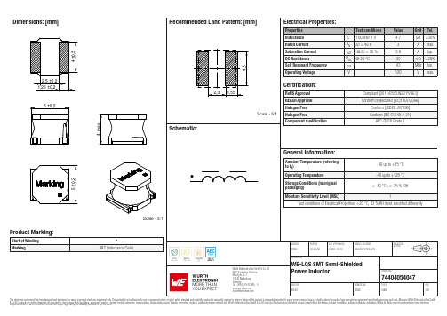
Dimensions: [mm]Scale - 5:174404054047BC74404054047T e m p e r a t u r eT pT L74404054047Cautions and Warnings:The following conditions apply to all goods within the product series of WE-LQS of Würth Elektronik eiSos GmbH & Co. KG:General:•This electronic component is designed and manufactured for use in general electronic equipment.•Würth Elektronik must be asked for written approval (following the PPAP procedure) before incorporating the components into any equipment in fields such as military, aerospace, aviation, nuclear control, submarine, transportation (automotive control, train control, ship control), transportation signal, disaster prevention, medical, public information network etc. where higher safety and reliability are especially required and/or if there is the possibility of direct damage or human injury.•Electronic components that will be used in safety-critical or high-reliability applications, should be pre-evaluated by the customer. •The component is designed and manufactured to be used within the datasheet specified values. If the usage and operation conditions specified in the datasheet are not met, the wire insulation may be damaged or dissolved.•Do not drop or impact the components, the component may be damaged.•Würth Elektronik products are qualified according to international standards, which are listed in each product reliability report. Würth Elektronik does not warrant any customer qualified product characteristics beyond Würth Elektroniks’ specifications, for its validity and sustainability over time.•The responsibility for the applicability of the customer specific products and use in a particular customer design is always within the authority of the customer. All technical specifications for standard products also apply to customer specific products.Product specific:Soldering:•The solder profile must comply with the technical product specifications. All other profiles will void the warranty.•All other soldering methods are at the customers’ own risk.•Strong forces which may affect the coplanarity of the components’ electrical connection with the PCB (i.e. pins), can damage the part, resulting in avoid of the warranty.Cleaning and Washing:•Washing agents used during the production to clean the customer application might damage or change the characteristics of the wire insulation, marking or plating. Washing agents may have a negative effect on the long-term functionality of the product.•Using a brush during the cleaning process may break the wire due to its small diameter. Therefore, we do not recommend using a brush during the PCB cleaning process.Potting:•If the product is potted in the customer application, the potting material may shrink or expand during and after hardening. Shrinking could lead to an incomplete seal, allowing contaminants into the core. Expansion could damage the components. We recommend a manual inspection after potting to avoid these effects.Storage Conditions:• A storage of Würth Elektronik products for longer than 12 months is not recommended. Within other effects, the terminals may suffer degradation, resulting in bad solderability. Therefore, all products shall be used within the period of 12 months based on the day of shipment.•Do not expose the components to direct sunlight.•The storage conditions in the original packaging are defined according to DIN EN 61760-2.•The storage conditions stated in the original packaging apply to the storage time and not to the transportation time of the components. Packaging:•The packaging specifications apply only to purchase orders comprising whole packaging units. If the ordered quantity exceeds or is lower than the specified packaging unit, packaging in accordance with the packaging specifications cannot be ensured. Handling:•Violation of the technical product specifications such as exceeding the nominal rated current will void the warranty.•Applying currents with audio-frequency signals may result in audible noise due to the magnetostrictive material properties.•The temperature rise of the component must be taken into consideration. The operating temperature is comprised of ambient temperature and temperature rise of the component.The operating temperature of the component shall not exceed the maximum temperature specified.These cautions and warnings comply with the state of the scientific and technical knowledge and are believed to be accurate and reliable.However, no responsibility is assumed for inaccuracies or incompleteness.Würth Elektronik eiSos GmbH & Co. KGEMC & Inductive SolutionsMax-Eyth-Str. 174638 WaldenburgGermanyCHECKED REVISION DATE (YYYY-MM-DD)GENERAL TOLERANCE PROJECTIONMETHODChrB.001.0062022-10-01DIN ISO 2768-1mDESCRIPTIONWE-LQS SMT Semi-ShieldedPower Inductor ORDER CODE74404054047SIZE/TYPE BUSINESS UNIT STATUS PAGEImportant NotesThe following conditions apply to all goods within the product range of Würth Elektronik eiSos GmbH & Co. KG:1. General Customer ResponsibilitySome goods within the product range of Würth Elektronik eiSos GmbH & Co. KG contain statements regarding general suitability for certain application areas. These statements about suitability are based on our knowledge and experience of typical requirements concerning the areas, serve as general guidance and cannot be estimated as binding statements about the suitability for a customer application. The responsibility for the applicability and use in a particular customer design is always solely within the authority of the customer. Due to this fact it is up to the customer to evaluate, where appropriate to investigate and decide whether the device with the specific product characteristics described in the product specification is valid and suitable for the respective customer application or not.2. Customer Responsibility related to Specific, in particular Safety-Relevant ApplicationsIt has to be clearly pointed out that the possibility of a malfunction of electronic components or failure before the end of the usual lifetime cannot be completely eliminated in the current state of the art, even if the products are operated within the range of the specifications.In certain customer applications requiring a very high level of safety and especially in customer applications in which the malfunction or failure of an electronic component could endanger human life or health it must be ensured by most advanced technological aid of suitable design of the customer application that no injury or damage is caused to third parties in the event of malfunction or failure of an electronic component. Therefore, customer is cautioned to verify that data sheets are current before placing orders. The current data sheets can be downloaded at .3. Best Care and AttentionAny product-specific notes, cautions and warnings must be strictly observed. Any disregard will result in the loss of warranty.4. Customer Support for Product SpecificationsSome products within the product range may contain substances which are subject to restrictions in certain jurisdictions in order to serve specific technical requirements. Necessary information is available on request. In this case the field sales engineer or the internal sales person in charge should be contacted who will be happy to support in this matter.5. Product R&DDue to constant product improvement product specifications may change from time to time. As a standard reporting procedure of the Product Change Notification (PCN) according to the JEDEC-Standard inform about minor and major changes. In case of further queries regarding the PCN, the field sales engineer or the internal sales person in charge should be contacted. The basic responsibility of the customer as per Section 1 and 2 remains unaffected.6. Product Life CycleDue to technical progress and economical evaluation we also reserve the right to discontinue production and delivery of products. As a standard reporting procedure of the Product Termination Notification (PTN) according to the JEDEC-Standard we will inform at an early stage about inevitable product discontinuance. According to this we cannot guarantee that all products within our product range will always be available. Therefore it needs to be verified with the field sales engineer or the internal sales person in charge about the current product availability expectancy before or when the product for application design-in disposal is considered. The approach named above does not apply in the case of individual agreements deviating from the foregoing for customer-specific products.7. Property RightsAll the rights for contractual products produced by Würth Elektronik eiSos GmbH & Co. KG on the basis of ideas, development contracts as well as models or templates that are subject to copyright, patent or commercial protection supplied to the customer will remain with Würth Elektronik eiSos GmbH & Co. KG. Würth Elektronik eiSos GmbH & Co. KG does not warrant or represent that any license, either expressed or implied, is granted under any patent right, copyright, mask work right, or other intellectual property right relating to any combination, application, or process in which Würth Elektronik eiSos GmbH & Co. KG components or services are used.8. General Terms and ConditionsUnless otherwise agreed in individual contracts, all orders are subject to the current version of the “General Terms and Conditions of Würth Elektronik eiSos Group”, last version available at .Würth Elektronik eiSos GmbH & Co. KGEMC & Inductive SolutionsMax-Eyth-Str. 174638 WaldenburgGermanyCHECKED REVISION DATE (YYYY-MM-DD)GENERAL TOLERANCE PROJECTIONMETHODChrB.001.0062022-10-01DIN ISO 2768-1mDESCRIPTIONWE-LQS SMT Semi-ShieldedPower Inductor ORDER CODE74404054047SIZE/TYPE BUSINESS UNIT STATUS PAGE。
德力西电气 工业用连接器 DHADEP22142R 产品规格书
产品规格书
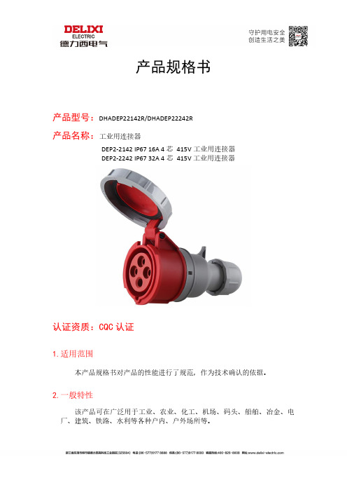
产品型号:DHADEP22142R/DHADEP22242R
产品名称:工业用连接器
DEP2-2142 IP67 16A 4芯415V工业用连接器
DEP2-2242 IP67 32A 4芯415V工业用连接器
认证资质:CQC认证
1.适用范围
本产品规格书对产品的性能进行了规范,作为技术确认的依据。
2.一般特性
该产品可在广泛用于工业、农业、化工、机场、码头、船舶、冶金、电厂、建筑、铁路、水利等各种户内、户外场所等。
3.产品结构
本产品为产品按照国家标准GB/T11918.1-2014、GB11918.2-2014设计生产, 产品规格为DEP2-2142 16A /DEP2-2242 32A 4芯415V工业用连接器,插座为3P+E 极,使用范围 380-415V,产品防护等级 IP67。
4.材质参数
5.技术特性
6.产品尺寸图
7.接线安装
Step1:分离护套
找到弹片位置,用改锥(螺丝刀)向下用力,红色加强筋中心线会从原来与白色中心线对其位置向一侧偏离,则可分离护套。
Step2:穿过线缆
按如下图示依次从护套穿过准备接入的线缆。
Step3:相序接线
按照L1、L2、L3和接线指示松开接线螺丝,用螺丝刀接对应线缆。
Step4:完成安装
对好位置,按护套上标识箭头锁紧产品,听到“嗒”声即可,并拧紧尾部螺旋塞。
派克核电门户网站产品说明书
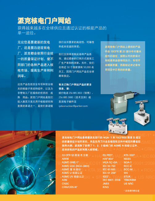
10 CFR 50 • AERB • ASME QME-1* • ASME QSC (NCA-3800) • ASME 第 III 部分 • ASME U核级认证核级认证 • ASN • CNSC CRN-N* HAF 604 • IAEA SC-QA 780 298* • IEEE* • ISO 9001: •E 派克核电门户网站无论您是要建新的发电厂,还是要改进现有电厂,派克都会依照行业统一的质量保证计划,使不同部门的各种产品进入核电市场,提高生产率和利润率。
这些产品包括安全专项和安全相关的核级子系统和组件,以及为非管制工厂区提供的优质的“成熟”商品。
派克门户网站是我们投入数百万美元用于核能研究和发展的承诺之一,是我们承诺提获得越来越多在全球供应且通过认证的核能产品的单一途径。
供行业所要求的高效性、可靠性和成本效益的体现。
我们支持单源购买各种产品系列,通过最新的订购方式提高工厂生产率和利润率。
另外,我们在将近 50 个国家拥有 50,000 名员工,因而门户网站产品在全球都有供应。
有关订购门户网站产品的更多信息,请:拨打电话 256 885 3833(销售)、256 885 3880(技术支持)或 发送电子邮件至 ipdusnuclear@parker .com派克核电门户网站是根据派克现行的 NQA- 1 和 10CFR50 附录 B 规定的质量保证计划开发的,并且采用了行业及规范性文件中规定的最佳实3 级阀门的 ASME N 核级认证外,派克核电门户网站上提供的产品符合 10CFR 第 21 部分中对基本组件的规定,按照认可的质保计划或是商品级物项执行。
专项不会提高质量,而是验证并记录专用项目中已有的的质量。
EU PED*HAF 604*IAEA SC-QA KTA 3507NNSANQA-1Parker Hannifin Ltd.Tachbrook Park DriveTachbrook Park,Warwick, CV34 6TU英国电话:+44 (0) 1926 317 878传真:+44 (0) 1926 317 855********************欧洲、中东和非洲AE – 阿联酋,迪拜电话:+971 4 8127100********************AT – 奥地利,维也纳新城电话:+43 (0)2622 23501-0*************************AT – 东欧,维也纳新城电话:+43 (0)2622 23501 900****************************AZ – 阿塞拜疆,巴库电话:+994 50 2233 458****************************BE/LU – 比利时,尼韦尔电话:+32 (0)67 280 900*************************BY – 白俄罗斯,明斯克电话:+375 17 209 9399*************************CH – 瑞士,埃托瓦电话:+41 (0)21 821 87 00*****************************CZ – 捷克共和国,Klecany电话:+420 284 083 111*******************************DE – 德国,卡尔斯特电话:+49 (0)2131 4016 0*************************DK – 丹麦,巴勒鲁普电话:+45 43 56 04 00*************************ES – 西班牙,马德里电话:+34 902 330 001***********************FI – 芬兰,万塔河电话:+358 (0)20 753 2500parker. ****************FR – 法国,Contamine s/Arve电话:+33 (0)4 50 25 80 25************************GR – 希腊,雅典电话:+30 210 933 6450************************HU – 匈牙利,布达佩斯电话:+36 23 885 470*************************IE – 爱尔兰,都柏林电话:+353 (0)1 466 6370*************************IT – 意大利,Corsico (MI)电话:+39 02 45 19 21***********************KZ – 哈萨克斯坦,阿拉木图电话:+7 7273 561 000****************************NL – 荷兰,奥尔登扎尔电话:+31 (0)541 585 000********************NO – 挪威,阿斯克尔电话:+47 66 75 34 00************************PL – 波兰,华沙电话:+48 (0)22 573 24 00************************PT – 葡萄牙,莱萨·达·帕尔梅拉电话:351 22 999 7360**************************RO – 罗马尼亚,布加勒斯特电话:+40 21 252 1382*************************RU – 俄罗斯,莫斯科电话:+7 495 645-2156************************SE – 瑞典,Spånga电话:+46 (0)8 59 79 50 00************************SK – 斯洛伐克,班斯卡·比斯特里察电话:+421 484 162 252**************************SL – 斯洛文尼亚,新梅斯托电话:+386 7 337 6650**************************TR – 土耳其,伊斯坦布尔电话:+90 216 4997081************************UA – 乌克兰,基辅电话:+380 44 494 2731*************************UK – 英国,沃里克电话:+44 (0)1926 317 878********************ZA – 南非,坎普顿公园电话:+27 (0)11 961 0700*****************************北美地区CA – 加拿大,安大略省米尔顿电话:+1 905 693 3000US – 美国,克利夫兰电话:+1 216 896 3000亚太地区AU – 澳大利亚,城堡山电话:+61 (0)2-9634 7777CN – 中国,上海电话:+86 21 2899 5000HK – 香港电话:+852 2428 8008IN – 印度,孟买电话:+91 22 6513 7081-85JP – 日本,东京电话:+81 (0)3 6408 3901KR – 韩国,首尔电话:+82 2 559 0400MY – 马来西亚,莎阿南电话:+60 3 7849 0800NZ – 新西兰,惠灵顿电话:+64 9 574 1744SG – 新加坡电话:+65 6887 6300TH – 泰国,曼谷电话:+662 186 7000-99TW – 台湾,台北电话:+886 2 2298 8987南美AR – 阿根廷,布宜诺斯艾利斯电话:+54 3327 44 4129BR – 巴西,圣若泽杜斯坎普电话:+55 800 727 5374CL – 智利,圣地亚哥电话:+56 2 623 1216MX – 墨西哥,阿波达卡电话:+52 81 8156 6000核电门户网站手册 M&K 12/10 1M派克授权的本地经销商© 2010 派克汉尼汾公司派克全球办事处联系信息欧洲产品信息中心免费电话:00 800 27 27 5374(AT, BE, CH, CZ, DE, DK, EE, ES, FI, FR, IE,IL, IS, IT, LU, MT, NL, NO, PL, PT, RU, SE,SK, UK, ZA)– 一点的方式。
Escha艾查工业自动化中文

扣扣2849595787
关于我们-About us !
艾查-立足于质量和能力在连接解 决方案和密封壳体技术方面拥有25 年的历史。
在德国Sauerland州Halver我们的生 产基地和海外工厂级工作人员已超过 300名员工。
我们的优势在于精于开 发和生产。
我们一直不断的开拓标准 产品线为客户提供恰当适用的部件。
新研发的产品具备很高的技术标准投 入量产---这也依赖于我们精湛的制造 技术。
我们的产品设计适用于恶劣的工业 环境,正在销往全世界。
上海公司的 成立强化了我们本土和海外的产品市 场。
针对您的应用,相信我们的产品 会为您提供可靠的信号传输和性能, 而我们的服务不仅限于这些。
我们期待着与您的合作!
艾查工业自动化
艾查工业自动化艾查工业自动化。
HEUFT SYSTEMTECHNIK GMBH 产品说明书

HEUFT SYSTEMTECHNIK GMBHAmWind1·56659Burgbrohl·Germany··**************Perfect PET!CUSTOMER CENTERviSiT US in OURself of the superior performance of our inspection and quality assurance systems – even with live tests using products from your own portfolio upon request.***************+49 2636 56 0HEUFT system sustainably in the HEUFT Training Center – not only theoretically but also directly at the device!****************** +49 2636 56 2671TeleService , the HEUFT PhoneService up to HEUFT DirectService visits – for a worldwide 24/7 support.************************+49 2636 56 278and events – including a tour of the premises, specialist lectures and practical presentations!*****************+49 2636 56 0Washing machineinfeed check based on the HEUFT InLine ISEmpty bottle inspectionpET inSpECTiOnHEUFT safeguards quality during the filling of returnable pET from the beginning to the end. non-brand, severely misshapen, contaminated and defective empty bottles are reliably detected and removed even before they canput downstream machines out of action. The emptybottle inspector only allows pET containers through afterthe cleaning process which can be safely filled. an inspec-tion is carried out as soon as the drink is inside that the quantity is correct and the bottle does not leak. Finally a detailed examination of all the closure elements ensures the integrity of the packaging and the unadulterated purity of the end product.From bottom to top, from inside to outside, from empty to full, from open to sealed, from bad to good, from con- taminated to pure, from holey to tight, from defective to perfect and from premium to standard. Indeed from A to Z:Cleaning machinepERFECT qUaliTyFROM THE bEginning TO THE EndpET inSpECTiOnHEUFT InLine ISEmpty PET bottle inspection with servo technology.Full coverageContinuous complete inspection of empty pET bottles for the reliable identification of residual liquid, contamination, mould, foreign objects, stress cracks, defective neck rings as well as finish and thread faults including soiled and damaged vent slots.Intelligent assessmentHEUFT reflexx² image processing system and smart algorithm in order to combine the results of a precise scuffing, crack and base wear detection for the reliable iden-tification and evaluation of returnable pET bottles which are too old and no longer useful.Exact adjustmentServo-controlled fine bottle alignment for even more precision during the all-around inspection and automatic adaptation of the transport and detection units for straightforward brand and format changes.Space-saving and cleanCompact construction (actual area < 1 m²) in accordance with the hygiene-optimised HEUFT CleanDesign .HEUFT squeezer IIQSHighly automated leakage check based on the HEUFT SPECTRUM II .Leakproof packaging and pure contents Reliable detection of minute leaks in filled bottles made of pET and other plastics for the sustainable safeguarding of packaging and product integrity.Full stabilityprecise measurement of the internal pressure of the container for stable full containers which can be optimally transported and stored.Outstanding detection reliability Comparative fill level detection in a non-compressed and compressed condition for maximum precision when identifying leaks.reliable and easy operationMaximally automated HEUFT SPECTRUM II system with self-explanatory audio- visual HEUFT NaVi user guidance.Label inspectionSidewall inspectionFinish inspectionReal-time image processingwith individual teach-inClosure defect MisshapenForeign objectMicroleakMicrocrackLeaking closureBase inspectionTorn labelDefective tamper evident ringN on -b r a n d M i s a l i g n m e n tIncorrect alignmentLeaking closureMicroleakFill management MicrocrackClosure inspectionClosurepET inSpECTiOnWashing machine infeed check based on theHEUFT SPECTRUMIIAll-around inspection of returnable PET bottles even before cleaning.Full line efficiency and full productivityEffective protection against productivity thwarting standstills to the bottle washing machine and other downstream devices due to the timely sorting out of unsuitable pET bottles.Maximum packaging and product safetyReliable identification and early rejection of empty bottles which are non-brand, oversized, misshapen, closed, extremely soiled and contain dangerous residual liquids or foreign objects not removed during cleaning.Maximum detection reliabilitypowerful sensor technologies, high-resolution optics and real-time image proces-sing system. innovative camera technology especially for the specific detection of non-brand label remains, imprints and embossing as well as the reliable determi-nation of the colouration and exact quantity of residual liquid on the base of the bottle.Simply automaticMaximally automated HEUFT HEUFT SPECTRUM II system with automatic verticaland guide rail adjustment as well as the self-explanatory audiovisual HEUFT NaVi user guidance.HEUFT FinalView IICAPDetailed closure inspection based on the HEUFT SPECTRUM II .Full closure safety and maximum product integrityContinuous all-around inspection of closures and their safety elements.Superior detection accuracyReliable identification of non-brand, canted, defective, leaking and incorrectly positioned closures as well as the clear detection of thread faults and damaged tamper evident and neck rings.Individual and flexibledifferent detection modules for specific tasks from inspecting colour logos to checking the closure alignment with millimetre precision.Highly automated and self-explanatorybrand changes at the push of a button and audiovisual step-by-step assistance for utmost operational reliability.。
AEG UPS产品说明书
Safety and General InformationInspect the package contents upon receipt. Notify the carrier and dealer if there is any damage.SAVE THESE INSTRUCTIONS - This section contains importantinstructions that should be followed during installation and maintenance of the UPS and batteries.• This UPS is intended for indoor use only.• Do not operate this UPS in direct sunlight, in contact with fluids, or where there isexcessive dust of humidity.• Connect the UPS power cable directly to a wall outlet.• Be sure that the air vents on the UPS are not blocked. Allow adequate space forproper ventilation.• CAUTION: Servicing of batteries should be performed or supervised by personnelknowledgeable about batteries and the required precautions.• CAUTION: Do not dispose of batteries in a fire. The batteries may explode.• CAUTION: Do not open or mutilate batteries. Released material is harmful to theskin and eyes. It may be toxic.• CAUTION: Before replacing batteries, remove conductive jewelry such as chains,wrist watches, and rings. High energy through conductive materials could causesevere burns.• CAUTION: Failed batteries can reach temperatures that exceed the burnthresholds for touchable surfaces.• CAUTION: A battery can present a risk of electrical shock and high short-circuitcurrent. The following precautions should be observed when working on batteries:–Disconnect the charging source prior to connecting or disconnecting batteryterminals.–Do not wear any metal objects including watches and rings.–Do not lay tools or metal parts on top of batteries.–Use tools with insulated handles.–Wear rubber gloves and boots.–Determine if battery is either intentionally or inadvertently grounded. Contactwith any part of a grounded battery can result in electric shock and burns byhigh short-circuit current. The risk of such hazards can be reduced if groundsare removed during installation and maintenance by a skilled person.• This manual can be downloaded from APC by Schneider Electric Website.Back-UPS Pro BR 1200/1600 SI2InventoryConnect the BatteryThe UPS is shipped with the battery disconnected.Lay the UPS with the battery door facing up. The arrows point to the locking tabs of thebattery compartment.Press the tabs downwards and pull thebattery door away from the unit to access the battery modules. Using the handles on both sides of thebattery, lift the battery 30 degrees upward to expose the battery connector. Connect the red wire as shown above.Push the battery into the unit.Replace the battery door.b u 476ab u 474aInstall PowerChute™ Personal Edition Software Use PowerChute Personal Edition software to configure the UPS settings. During apower outage, PowerChute will save any open files on your computer and shut it down. When power is restored, it will restart the computer.Note: PowerChute is only compatible with a Windows operating system. If you are using Mac OSX, use the native shutdown feature to help protect your system. See the documentation provided with your computer.InstallationUse the USB communication cable supplied with the Back-UPS to connect the data port on the Back-UPS to the USB port on your computer. On the computer, go to Search for “PowerChute Personal Edition” then click on “ViewDetails” to download the latest version of PCPE software. Click the download link and select Software product. Select the appropriate operating system. Followdirections to download the software.Back-UPS Pro BR 1200/1600 SI3Connect the EquipmentBattery backup and surge protected outletsWhen the Back-UPS is receiving input power, the Battery Backup with SurgeProtection outlets will supply power to connected equipment. During a poweroutage or other AC problems, the Battery Backup outlets receive power for a limited time from the Back-UPS.Connect equipment such as printers, fax machines, scanners, or other peripherals that do not need battery backup power to the Surge Protection Only outlets. These outlets provide full-time protection from surges even if the Back-UPS is switched OFF.USB and Serial Data port To use PowerChute Personal Edition, connect the supplied USB cable or an optional serial cable (not supplied).TelephoneCable SurgeProtected ports Connect the ground lead from an additional surge suppression device such as a stand-alone data line surge protector.AC PowerInput Use a power cable to connect the unit to AC power.Battery Backup outlets withSurgeProtection During a power outage or other AC problems, the Battery Backup outlets receive power for a limited time from the Back-UPS. Connect essential equipment such as desktop computer, computer monitor, modem or other data sensitive devices into these outlets.Circuit Breaker Use to reset the system after anoverload condition has occurredcausing the circuit breaker to trip.In/Out Ethernet surge-protectedports Use an Ethernet cable to connect a cable modem to the I N port, and connect a computer to the O UT port.SurgeProtectedoutlets These outlets provide full-timeprotection from surges, even if theBack-UPS is off. Connectequipment such as printers andscanners that do not require batterybackup protection.Back-UPS Pro BR 1200/1600 SI4OperationPower saving displayThe display interface can be configured to be continuously illuminated, or to save energy, it can be configured to darken after a period of inactivity.1. Full Time Mode: Press and hold DISPLAY for two seconds. The display willilluminate and the Back-UPS will beep to confirm the Full Time mode.2. Power Saving Mode: Press and hold DISPLAY for two seconds. The display willdarken and the Back-UPS will beep to confirm the Power Saving mode. While inPower Saving Mode, the display will illuminate if a button is pressed, it thendarkens after 60 seconds of no activity.Unit sensitivityAdjust the sensitivity of the Back-UPS to control when it will switch to battery power; the higher the sensitivity, the more often the Back-UPS will switch to battery power.1. Be sure the Back-UPS is connected to AC power, but is OFF.2. Press and hold the P OWER button for six seconds. The L OAD C APACITY bar willflash on and off, indicating that the Back-UPS is in programming mode.3. Press P OWER again to rotate through the menu options. Stop at selectedsensitivity. The Back-UPS will beep to confirm the selection.Generator Sensitivity Default Sensitive LoadsLow sensitivity Medium sensitivity (Default)High sensitivity156-300 Vac176-294 Vac176-288 V acInput voltage is extremely low or high. (Not recommended for computer loads.)The Back-UPS frequentlyswitches to battery power.The connected equipment issensitive to voltagefluctuations.Back-UPS Pro BR 1200/1600 SI5Back-UPS Pro BR 1200/1600 SI6Front panel buttons and display interfaceUse the three buttons on the front panel of the Back-UPS and the display interface to configure the Back-UPS.Front panelDisplay buttonPower On/Off button Mute button Display interface USB charging ports:The 2 USB portsprovide a total of 15W of DC power, and will provide power even when the UPS is on battery.On Line: The Back-UPS is supplying conditioned AC power to connected equipmentLoad Capacity: The load is indicated by the number of sections illuminated, one to five. Each bar represents 20% of the load.Battery Capacity: The battery charge level is indicated by the number of sections illuminated. When all five blocks are illuminated, the Back-UPS is at full charge. When one block is filled, the Back-UPS is near the end of its battery capacity, the indicator will flash and the Back-UPS will beep continuously.Low Battery: When battery capacity reaches the empty level, the Back-UPS is nearing shutdown and the indicator will flash accompanied by a continuous beep.Replace Battery: The battery is nearing the end of its useful life. When the display shows a flashing Replace Battery icon and an empty Battery Capacity icon, replace the battery as early as possible.On Battery: The Back-UPS is supplying battery backup power to the connected equipment, it will beep four times every 30 seconds.Event: The event counter shows the number of events that occurred that caused the Back-UPS to switch to on-battery operation.System Error Detected: The system has an error. The error number will illuminate on the display interface. See “System errors” on page 8.Back-UPS Pro BR 1200/1600 SI 7Alarms and System ErrorsAudible indicatorsStatus iconsOverload: The power demand from the load has exceeded the capacity of the Back-UPS.Mute: If the line through the speaker icon is illuminated, the audible alarm has been turned off.Out: Output voltage, frequency In: Input voltage.Automatic Voltage Regulation:When illuminated, the Back-UPS is compensating for low input voltageWhen illuminated, the Back-UPS is compensating for high input voltage.Estimated Run Time: This indicates the battery runtime minutes that remain if the Back-UPS switches to battery power.Load: The total load in watts (W) or percentage (%) used by the devices connected to the Battery Backup outlets.Four Beeps Every 30 Seconds Back-UPS is running on battery. You should consider saving any work in progress.Continuous Beeping Low battery condition and battery run-time is very low. Promptly save any work in progress, exit all open applications, and shut down the operating system.Continuous toneBattery Backup outputs are overloaded. Chirps every 2 Seconds Battery is disconnected.Continuous chirpingBattery did not pass the automatic diagnostic test and should be replaced as early as possible. Pressing the MUTE button pauses the chirping.If these icons are flashing...This may be the problem.The Back-UPS is overloaded. Disconnect one of the items connected to the Back-UPS. If the Overload icon stops flashing, the Back-UPS is no longer overloaded and will continue to operate normally.The Back-UPS is operating on AC power, but the battery is notfunctioning properly. Contact Schneider Electric IT (SEIT) Customer Service to order a replacement battery. See “Battery Replacement” on page 12.The Back-UPS is operating on battery power and the battery power is getting low. Shut down all connected equipment to avoid losing an unsaved data. When possible, connect the Back-UPS to AC power to recharge the battery.The battery is not connected. See “Connect the Battery” on page 2 tomake sure battery wires are connected properly.Back-UPS Pro BR 1200/1600 SI8System errorsThe Back-UPS will display these error messages. Except for errors F01 and F02, contact SEIT Technical Support.F01On-Battery Overload Turn the Back-UPS off. Disconnect non-essentialequipment from the BatteryBackup outlets and the turn Back-UPS on.F02On-Battery Output ShortTurn the Back-UPS off.Disconnect all equipment from the Battery Backup outlets andthe turn Back-UPS on.Re-connect equipment one item at a time. If the output is tripped again, disconnect the device that caused the error.F04Clamp ShortErrors F04-F09 cannot be corrected by the user, contact SEIT Technical Support for assistance.F05Charge Error F06Relay Welding F07Temperature F08Fan Error F09Internal ErrorFunction Button Quick ReferenceFunction ButtonTiming(seconds)UPSStatus DescriptionPowerPower On0.2Off Press P OWER to start receiving input AC power. If AC input power is not available, the Back-UPS will run on battery power.Power Off2On The Back-UPS is not receiving input AC power, but is providing surge protection.DisplayStatusInquiry0.2On Verify the status or condition of the Back-UPS. The LCD will illuminate for 60 seconds. Press the button the toggle into various information.Full-Time/Power-Saving mode 2OnThe LCD will illuminate and the Back-UPS will beepto confirm the Full-Time mode. The LCD will darkenand the Back-UPS will beep to confirm the Power-Saving mode. While in Power-Saving Mode, the LCDwill illuminate if a button is pressed, then darkens after60 seconds of no activity.MuteEnable/ Disable mode 2OnEnable or disable the audible alarms. The Mute iconwill illuminate and the Back-UPS will beep one time.Sensitivity6Off The Load Capacity icon will blink, indicating that the Back-UPS is in programming mode. Use the P OWER button to scroll through Low, Medium, and High, stop at selected sensitivity. The Back-UPS will beep to confirm selection. See "Unit sensitivity" for details.Self-Test(manual)6On The Back-UPS will perform a test of the internal battery. Note: This will happen automatically when the Back-UPS is turned ON or when the Back-UPS previously detected a bad battery.EventReset0.2On When the Event screen is visible, press and holdD ISPLAY, then press POWER, to clear the detected error event counter.ErrorReset2Error After an error has been identified, press P OWER to remove the visual indication and return to standbystatus.Back-UPS Pro BR 1200/1600 SI9TroubleshootingProblem Possible Cause Corrective ActionBack-UPS will not switch on.The Back-UPS is not connected to ACpower.Be sure that the Back-UPS is securelyconnected to an AC outlet.The circuit breaker has been tripped.Disconnect non-essential equipmentfrom the Back-UPS. Reset the circuitbreaker. Re-connect equipment oneitem at a time. If the circuit breaker istripped again, disconnect the device thatcaused the trip.The internal battery is not connected.Connect the battery.The AC input voltage is out of range.Adjust the transfer voltage andsensitivity range.The Back-UPS does not provide power during a AC power outage.Be sure that essential equipment isnot plugged into a S URGE O NLYoutlet.Disconnect equipment from the S URGEO NLY outlet and re-connect to a BatteryBackup outlet.The Back-UPS is operating on battery power, while connected to AC power.The plug has partially pulled out ofthe wall outlet, the wall outlet is nolonger receiving AC power, or thecircuit breaker has been tripped.Be sure that the plug is fully insertedinto the wall outlet. Be sure that thewall outlet is receiving AC power bychecking it with another device. The Back-UPS is performing anautomatic self test.No action is necessary.The AC input voltage is out of range,the frequency is out of range, or thewaveform is distorted.Adjust the transfer voltage andsensitivity range.The Back-UPS does not provide the expected amount of backup time.Battery Backup outlets may be fullyor improperly loaded.Disconnect non-essential equipmentfrom the Battery Backup outlets andconnect the equipment to S URGEoutlets.The battery was recently dischargeddue to a power outage and has notfully recharged.Charge the battery cartridge for 16hours.The battery has reached the end of itsuseful life.Replace the battery.The R EPLACE B ATTERY indicator is illuminated.The battery has reached the end of itsuseful life.Replace the battery as early as possible.The O VERLOAD indicator is illuminated.The equipment connected to theBack-UPS is drawing more powerthan the Back-UPS can provide.Disconnect non-essential equipmentfrom the Battery Backup outlets andconnect the equipment to S URGEoutlets.The S YSTEM E RROR indicator is illuminated, all the front panel indicators are flashing.There is an internal error.Determine which internal errormessage is displayed by matching thenumber displayed on the LCD with thecorresponding Error Message (see"System errors") and contact SEITTechnical Support.Back-UPS Pro BR 1200/1600 SI10SpecificationsBack-UPS Pro BR 1200/1600 SI11© 2022 APC by Schneider Electric. APC, the APC logo, Back-UPS, andPowerChute are owned by Schneider Electric Industries S.A.S. or their affiliated companies. All other trademarks are property of their respective owners.EN 990-91254B02/2022Battery ReplacementThe battery typically lasts for 3 to 5 years, a shorter period if subjected to frequent outages or elevated temperatures. Battery replacement parts for Back-UPS Pro BR1200SI is APCRBC161, and for BR1600SI is APCRBC163. Delaying the replacement of parts may corrode the batteries in the cartridge. Recycle spentbattery cartridges.WarrantyThe standard warranty is three (3) years from the date of purchase, valid inEuropean Community. For all other regions, the standard warranty is two (2) years from the date of purchase. Schneider Electric IT (SEIT) standard procedure is to replace the original unit with a factory reconditioned unit. Customers who must have the original unit back due to the assignment of asset tags and set depreciation schedules must declare such a need at first contact with an SEIT Technical Support representative. SEIT will ship the replacement unit once the defective unit has been received by the repair department, or cross-ship upon the receipt of a valid credit card number. The customer pays for shipping the unit to SEIT. SEIT pays ground freight transportation costs to ship the replacement unit to the customer.APC by Schneider Electric IT Customer Support WorldwideFor country specific customer support, go to the APC by Schneider Electric Web site, .。
和泰(EXHEAT)工业产品 - 标准产品说明书

Industrial Ltd和泰(EXHEAT)标准产品标准产品和泰(EXHEAT)的工业部门为工业上广泛而多样的电加热系统需求提供了最直接便利的解决方案。
和泰(EXHEAT)生产的所有在危险区域应用的加热器都完全符合IECEx系统,CSA或者欧洲ATEX防爆标准局认证的最新要求。
在标准产品不能完全满足客户的需求时,和泰(EXHEAT)的销售工程师和设计人员可以设计定制的危险区或者安全区应用的电加热器。
跟客户紧密的联系和咨询以及我们多年的经验,可以确保我们的客户获得最适合他们应用的加热器。
所有的和泰(EXHEAT)电加热器都在英国生产和库存。
在新加坡也有一部分库存,满足快速交货的需要。
和泰(EXHEAT)工业产品范围• 危险区域空气加温器,箱体加热器和工业用热空气循环对流加热器• 防爆散热器,风扇式空气加热器,沸水器,浸入式加热器和自动调温器• 有排气口和没有排气口的贮水式热水器和桶式加热器• 工业用,洗礼用和便携式的浸入式加热器• 加热器元件加热棒式和芯式,电伴热,自动调温器,控制柜防爆的仪器仪表壳体和变送器•2防爆区域加热和控制方案3功率等级认证箱体电压等级安装方式500瓦到2千瓦IECEx 以及 ATEX 认证的 Ex’d’ IIC T2 到 T4, Ex tD A21 IP66 T300°C 到 T135°C EN/IEC60079-0, EN/IEC60079-1, EN/IEC61241-0 和 EN/IEC61241-1低碳钢粉末涂层,橙色或灰色,不锈钢可选单相230/254V 或者 110V标准配置有预先钻孔的支撑脚控制系统可按照需要采用和泰(EXHEAT)远程控制自动调温器,应用于安全或者危险区域(请参见本手册最后一页)FWD系列的空气加热器,设计用于较小的工作或者存储空间,位于1区,2区,以及21区和22区的危险区域。
气体等级IIA,IIB或者IIC。
4和泰(EXHEAT)也提供FWD-T系列的空气加热器,配备容易调控的外部自动调温器,设计用于较小的工作或者存储空间,位于1区,2区,以及21区和22区的危险区域。
德国IMC数据采集系统

德国imc数据采集系统可广泛测量电压、电流、温度、应力应变、加速度计、数字输入/输出、转角、角速度、位移、频率等工业常用信号,同时还提供了功能强大的操控软件搭配使用,无需任何编程、只要接入电源和信号线,即可开始测量。
为了满足客户及现场使用环境的要求,imc数采系统可分为:便携式、模块集成式、分布式、多通道型、恶劣环境坚固型、总线采集器等多个类型产品。
各种类型的硬件,用户可搭配imc提供的COM/Active X系统程序发展界面,灵活使用熟悉的VB、VC++或Delphi等常用编程语言来定制自己的测量系统。
imc数采系统正服务于汽车及零部件、卡车及工程车辆、铁路机车、航天、土木工程、船舶等测试领域。
IMC数据采集系统、IMC模块
上海智川工贸有限公司专业供应德国IMC数据采集系统、IMC模块。
艾德克 直流电子负载 IT821 说明书
上述的保证不适用因以下情况所造成的损坏: 顾客不正确或不适当的维修产品; 顾客使用自己的软件或界面; 未经授权的修改或误用; 在指定的环境外操作本产品,或是在不当的地点配置及维修。 顾客自行安装的电路造成的损坏,或顾客使用自己的产品造成的瑕疵。
Compliance Statements
Disposal of Old Electrical & Electronic Equipment (Applicable in the European Union and other European countries with separate collection systems)
安全标识
警告 它提醒使用者,注意某些可能导致人体伤亡的操作程序、作法、状况等事项。 注意 它提醒使用者可能导致仪器损坏或数据永久损失的操作程序、作法、状况等事项。
接地地线识
高压危险
参阅相关文件中的警告,注意提示
关于IT8211
IT8211 全数控电子负载 (60V/30A/ 150W) 具有10mV,1mA的高解析度和精度,让您的的测试结果更加准确。 具定电压,定电流和定电阻模式,短路测试的功能,简洁的操作及显 示介面,內建4*100 组快速键设定,让您轻松并快速的完成各种复杂测
面板布局
电压设定/测量显示 步进值B+快捷键预设置B 步进值A+快捷键预设置A 步进值C+快捷键预设置C 步进值D+快捷键预设置D
电流设定/测量显示 快捷键储存(shift)
左移键+快捷键A 功能设置(shift) 显示切换+快捷键C
短路操作 输入开启/关断键
进气口
主电源开关
Setup indicator
eichrecht certification-related

eichrecht certification-related
Eichrecht certification-related通常指与德国Eichrecht 认证相关的内容。
Eichrecht 是德国的一项计量法,规定了度量衡的准确性和一致性。
在与 Eichrecht 认证相关的上下文中,可能涉及以下方面:
1. 计量器具的校准和检定:根据 Eichrecht 法,各种计量器具(如秤、尺子、温度计等)需要定期进行校准和检定,以确保其测量结果的准确性。
2. 认证机构:为了确保计量器具的准确性,德国有专门的认证机构负责对计量器具进行检测和认证。
这些机构遵循 Eichrecht 法的要求,对计量器具进行校准、检定和认证。
3. 合规性:企业和组织需要确保其使用的计量器具符合 Eichrecht 法的规定,并获得必要的认证和检定证书。
这有助于确保产品质量、贸易公平和消费者权益。
4. 培训和专业知识:与 Eichrecht 认证相关的领域还包括培训和专业知识的获取。
相关人员需要了解 Eichrecht 法的要求,掌握计量器具的校准和检定技术,以确保合规性和准确性。
需要注意的是,具体的 Eichrecht certification-related 内容可能因行业、地区和具体需求而有所不同。
如果你需要更详细的信息,建议参考相关的法律法规、行业标准或咨询专业的计量认证机构。
2304115资料
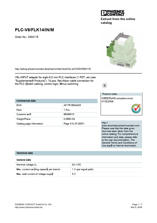
Extract from the online catalog PLC-V8/FLK14/IN/MOrder No.: 2304115http://eshop.phoenixcontact.de/phoenix/treeViewClick.do?UID=2304115V8L-INPUT adapter for eight 6.2 mm PLC interfaces (1 PDT, etc./see"Supplementary Products"). 14-pos. flat-ribbon cable connection for the PLC system cabling, control logic: Minus switchinghttp:// Please note that the data givenhere has been taken from theonline catalog. For comprehensiveinformation and data, please referto the user documentation. TheGeneral Terms and Conditions ofUse apply to Internet downloads.Technical dataGeneral dataNominal voltage U N24 V DC Max. current carrying capacity per branch1 A (per signal path)Max. total current of voltage supply 3 ANumber of positions14Length100 mmWidth49.6 mmHeight94 mmStatus display LED greenAmbient temperature (operation)-20 °C ... 60 °CAmbient temperature (storage/transport)-20 °C ... 70 °CTest voltage500 V (50 Hz, 1 min.)Test voltage contact/contact0.8 kV ACMounting position AnyAssembly instructions In rows with zero spacingStandards/regulations IEC 60664DIN EN 50178IEC 62103Pollution degree2Surge voltage category IIIConnection dataConnection 1Power supplyNumber of connections1Type of connection Screw connectionConductor cross section solid min.0.2 mm2Conductor cross section solid max. 4 mm2Conductor cross section stranded min.0.2 mm2Conductor cross section stranded max. 2.5 mm2Conductor cross section AWG/kcmil min.24Conductor cross section AWG/kcmil max12Stripping length8 mmScrew thread M 3Connection 2Signal levelType of connection Flat-ribbon cable connector, in acc. with IEC 60603-13(engagement catches based on IEC 60603-13) Number of positions14Certificates / Approvals Approval logorequested approbations Certification GL Additional productsItemDesignation Description General 2966728PLC-OSC- 24DC/48DC/100PLC interface, consisting of base terminal block PLC-BSC withscrew connection and pluggable miniature optocoupler, formounting on mounting rail NS 35/7.5, input: 24 V DC, output: 3-48V DC/ 100 mA2966773PLC-OSC- 24DC/48DC/100/SEN PLC sensor relay, consisting of base terminal block PLC-BSC...SEN with screw connection and pluggable miniatureoptocoupler, for assembly on mounting rail NS 35/7.5, input: 24 VDC, output: 3-48 V DC/ 100 mA2966993PLC-OSC- 48DC/48DC/100PLC interface, consisting of base terminal block PLC-BSC withscrew connection and pluggable miniature optocoupler, formounting on mounting rail NS 35/7.5, input: 48 V DC, output: 3-48V DC/ 100 mA2967455PLC-OSC- 60DC/48DC/100PLC interface, consisting of base terminal block PLC-BSC withscrew connection and pluggable miniature optocoupler, formounting on mounting rail NS 35/7.5, input: 60 V DC, output: 3-48V DC/ 100 mA2966744PLC-OSC-120UC/48DC/100PLC interface, consisting of base terminal block PLC-BSC withscrew connection and pluggable miniature optocoupler, formounting on mounting rail NS 35/7.5, input: 120 V AC/ 110 V DC /output: 3-48 V DC/ 100 mA2966799PLC-OSC-120UC/48DC/100/SEN PLC sensor relay, consisting of base terminal block PLC-BSC...SEN with screw connection and pluggable miniatureoptocoupler, for assembly on mounting rail NS 35/7.5, input: 120V AC/ 110 V DC / output: 3-48 V DC/ 100 mA2966757PLC-OSC-230UC/48DC/100PLC interface, consisting of base terminal block PLC-BSC withscrew connection and pluggable miniature optocoupler, formounting on mounting rail NS 35/7.5, input: 230 V AC/ 220 V DC /output: 3-48 V DC/ 100 mA2966809PLC-OSC-230UC/48DC/100/SENPLC sensor relay, consisting of base terminal block PLC-BSC...SEN with screw connection and pluggable miniatureoptocoupler, for assembly on mounting rail NS 35/7.5, input: 230V AC/ 220 V DC / output: 3-48 V DC/ 100 mA2967549PLC-OSP- 24DC/48DC/100PLC interface, consisting of base terminal block PLC-BSP... withspring-cage connection and pluggable miniature optocoupler, formounting on mounting rail NS 35/7.5, input: 24 V DC, output: 3-48V DC/ 100 mA2967578PLC-OSP- 24DC/48DC/100/SEN PLC sensor relay, consisting of base terminal block PLC-BSP...SEN with spring-cage connection and pluggable miniatureoptocoupler, for assembly on mounting rail NS 35/7.5, input: 24 VDC, output: 3-48 V DC/ 100 mA2967743PLC-OSP- 48DC/48DC/100PLC interface, consisting of base terminal block PLC-BSP... withspring-cage connection and pluggable miniature optocoupler, formounting on mounting rail NS 35/7.5, input: 48 V DC, output: 3-48V DC/ 100 mA2967756PLC-OSP- 60DC/48DC/100PLC interface, consisting of base terminal block PLC-BSP... withspring-cage connection and pluggable miniature optocoupler, formounting on mounting rail NS 35/7.5, input: 60 V DC, output: 3-48V DC/ 100 mA2967552PLC-OSP-120UC/48DC/100PLC interface, consisting of base terminal block PLC-BSP... withspring-cage connection and pluggable miniature optocoupler, formounting on mounting rail NS 35/7.5, input: 120 V AC/ 110 V DC /output: 3-48 V DC/ 100 mA2967581PLC-OSP-120UC/48DC/100/SEN PLC sensor relay, consisting of base terminal block PLC-BSP...SEN with spring-cage connection and pluggable miniature optocoupler, for assembly on mounting rail NS 35/7.5, input: 120 V AC/ 110 V DC / output: 3-48 V DC/ 100 mA2967565PLC-OSP-230UC/48DC/100PLC interface, consisting of base terminal block PLC-BSP... withspring-cage connection and pluggable miniature optocoupler, formounting on mounting rail NS 35/7.5, input: 230 V AC/ 220 V DC /output: 3-48 V DC/ 100 mA2967594PLC-OSP-230UC/48DC/100/SEN PLC sensor relay, consisting of base terminal block PLC-BSP...SEN with spring-cage connection and pluggable miniature optocoupler, for assembly on mounting rail NS 35/7.5, input: 230 V AC/ 220 V DC / output: 3-48 V DC/ 100 mA2966919PLC-RSC- 12DC/21AU PLC relay, consisting of base terminal block PLC-BSC.../21 withscrew connection and pluggable miniature relay with multi-layercontact, for assembly on mounting rail NS 35/7.5, 1 PDT, inputvoltage 12 V DC2966317PLC-RSC- 24DC/1AU/SEN PLC sensor relay, consisting of base terminal block PLC-BSC...SEN with screw connection and pluggable miniature relaywith multi-layer contact, for assembly on mounting rail NS 35/7.5,1 N/O contact, input voltage 24 V DC2966265PLC-RSC- 24DC/21AU PLC relay, consisting of base terminal block PLC-BSC.../21 withscrew connection and pluggable miniature relay with multi-layercontact, for assembly on mounting rail NS 35/7.5, 1 PDT, inputvoltage 24 V DC2966278PLC-RSC- 24UC/21AU PLC relay, consisting of base terminal block PLC-BSC.../21 withscrew connection and pluggable miniature relay with multi-layercontact, for assembly on mounting rail NS 35/7.5, 1 PDT, inputvoltage 24 V AC/DC2966126PLC-RSC- 48DC/21AU PLC relay, consisting of base terminal block PLC-BSC.../21 withscrew connection and pluggable miniature relay with multi-layercontact, for assembly on mounting rail NS 35/7.5, 1 PDT, inputvoltage 48 V DC2966142PLC-RSC- 60DC/21AU PLC relay, consisting of base terminal block PLC-BSC.../21 withscrew connection and pluggable miniature relay with multi-layercontact, for assembly on mounting rail NS 35/7.5, 1 PDT, inputvoltage 60 V DC2966320PLC-RSC-120UC/1AU/SEN PLC sensor relay, consisting of base terminal block PLC-BSC...SEN with screw connection and pluggable miniature relaywith multi-layer contact, for assembly on mounting rail NS 35/7.5,1 N/O contact, input voltage 120 V AC / 110 V DC2966281PLC-RSC-120UC/21AU PLC relay, consisting of base terminal block PLC-BSC.../21 withscrew connection and pluggable miniature relay with multi-layercontact, for assembly on mounting rail NS 35/7.5, 1 PDT, inputvoltage 120 V AC / 110 V DC2966333PLC-RSC-230UC/1AU/SEN PLC sensor relay, consisting of base terminal block PLC-BSC...SEN with screw connection and pluggable miniature relaywith multi-layer contact, for assembly on mounting rail NS 35/7.5,1 N/O contact, input voltage 230 V AC / 220 V DC2966294PLC-RSC-230UC/21AU PLC relay, consisting of base terminal block PLC-BSC.../21 withscrew connection and pluggable miniature relay with multi-layercontact, for assembly on mounting rail NS 35/7.5, 1 PDT, inputvoltage 230 V AC / 220 V DC2967442PLC-RSP- 12DC/21AU PLC relay, consisting of base terminal block PLC-BSP.../21 withspring-cage connection and pluggable miniature relay with multi-layer contact, for assembly on mounting rail NS 35/7.5, 1 PDT,input voltage 12 V DC2967374PLC-RSP- 24DC/1AU/SEN PLC sensor relay, consisting of base terminal block PLC-BSP...SEN with spring-cage connection and pluggable miniaturerelay with multi-layer contact, for assembly on mounting rail NS35/7.5, 1 N/O contact, input voltage 24 V DC2966540PLC-RSP- 24DC/21AU PLC relay, consisting of base terminal block PLC-BSP.../21 withspring-cage connection and pluggable miniature relay with multi-layer contact, for assembly on mounting rail NS 35/7.5, 1 PDT,input voltage 24 V DC2966553PLC-RSP- 24UC/21AU PLC relay, consisting of base terminal block PLC-BSP.../21 withspring-cage connection and pluggable miniature relay with multi-layer contact, for assembly on mounting rail NS 35/7.5, 1 PDT,input voltage 24 V AC/DC2966566PLC-RSP- 48DC/21AU PLC relay, consisting of base terminal block PLC-BSP.../21 withspring-cage connection and pluggable miniature relay with multi-layer contact, for assembly on mounting rail NS 35/7.5, 1 PDT,input voltage 48 V DC2966579PLC-RSP- 60DC/21AU PLC relay, consisting of base terminal block PLC-BSP.../21 withspring-cage connection and pluggable miniature relay with multi-layer contact, for assembly on mounting rail NS 35/7.5, 1 PDT,input voltage 60 V DC2967390PLC-RSP-120UC/1AU/SEN PLC sensor relay, consisting of base terminal block PLC-BSP...SEN with spring-cage connection and pluggable miniaturerelay with multi-layer contact, for assembly on mounting rail NS35/7.5, 1 N/O contact, input voltage 120 V AC/ 110 V DC 2966582PLC-RSP-120UC/21AU PLC relay, consisting of base terminal block PLC-BSP.../21 withspring-cage connection and pluggable miniature relay with multi-layer contact, for assembly on mounting rail NS 35/7.5, 1 PDT,input voltage 120 V AC/110 V DC2967413PLC-RSP-230UC/1AU/SEN PLC sensor relay, consisting of base terminal block PLC-BSP...SEN with spring-cage connection and pluggable miniaturerelay with multi-layer contact, for assembly on mounting rail NS35/7.5, 1 N/O contact, input voltage 230 V AC/ 220 V DC 2966647PLC-RSP-230UC/21AU PLC relay, consisting of base terminal block PLC-BSP.../21 withspring-cage connection and pluggable miniature relay with multi-layer contact, for assembly on mounting rail NS 35/7.5, 1 PDT,input voltage 230 V AC/220 V DC2296870PLC-VT VARIOFACE feed-through terminal block (two-conductorconnection), for PLC-RELAY universal series2296854PLC-VT/LA VARIOFACE feed-through terminal block (2-wire connection), forPLC-RELAY universal series, with light indicator 24 V DC DrawingsCircuit diagramConnection scheme: PLC-V8/FLK14/IN/MAddressPHOENIX CONTACT GmbH & Co. KGFlachsmarktstr. 832825 Blomberg,GermanyPhone +49 5235 3 00Fax +49 5235 3 41200http://www.phoenixcontact.de© 2008 Phoenix ContactTechnical modifications reserved;。
- 1、下载文档前请自行甄别文档内容的完整性,平台不提供额外的编辑、内容补充、找答案等附加服务。
- 2、"仅部分预览"的文档,不可在线预览部分如存在完整性等问题,可反馈申请退款(可完整预览的文档不适用该条件!)。
- 3、如文档侵犯您的权益,请联系客服反馈,我们会尽快为您处理(人工客服工作时间:9:00-18:30)。
2-路 连接
类型 MB_ M8x1 类型 MB_ M12x1
类型 S55 | M 8x1/M12x1
类型 S89 | M 8x1/M12x1
输入/输出分线盒
T型-连接 Y型-分离器 适配器 M 12 x1 M8x1/Ø8 快接
M 12x1 M 8x1 /Ø 8 快接/M12x1 M 8x1 /M 12x1
材 质
M 23x1
M 16x
M 12x1
AL -
W
WAK E*
3-
m/
S370
电缆材质 电缆长度 [m] 针脚数 *可选:V4A 锁定机制 圆型连接器 M12x1 | WAK: 孔头(母头): f W: 直角型: ; | 无: 直线型: # 自动化工业
产品系列 AL_M12x1
附件
防护帽, 防护塞, 保护管 装配-安全解决方案 扭矩-成套扳手
T图纸尺寸 输入/输出分线盒 M 8x1 /Ø 8 快接 | M12x1 M 8x1 /Ø 8 快接 | M12x1 | S89 M 8x1 /M 12x1
标签
法兰的备用螺母, 焊料标签
技术数据
执行标准, 认证, IP, 技术参数, 接线 说明, 电缆材质, 色彩导引, AWG vs. mm²...
类别 AL: f | #| ; AL: f | #| ;| LED AL: m | #| ; AL: 连接电缆 AL: f | #| ;| AL: m| #| ;| AL: 连接电缆
圆形连接 器应用于用
前-面板 安装
电线连接的设备安装,焊接或印片
后-面板 安装
接触PCB装配。 带有不锈钢螺母的 无PVC圆形连接器应用于食品行业 工作温度可达150°,最高工作温度可至200°.
AL-WAK4-m/P00 8049341 8051055 8051056
AL-WAK5-m/P00 8051077 8051078 8051079
AL-WAK4.5-m/P00 8051067 8051068 8051069
AL-WAK8-m/P00 8051089 8051090 8051091
类别 f|#
f|;
6
电缆材质 PUR | S370 PVC | P00 PVC | P01 PUR | S370 PVC | P00 PVC | P01
针脚数 3 4
4+PE 5 8 12 3 4
4+PE 5 8 12 3 4
4+PE 5 8 12 3 4
4+PE 5 8 12 3 4
4+PE 5 8 12 3 4
AL-WWAK5-m/S370 8046021 8046022 8046023
AL-WWAK4.5-m/S370 8043826 8043827 8043828
AL-WWAK8-m/S370 8046906 8046907 8046908
AL-WWAK12-m/S370 8046923 8046924 8046925
AL-WAK4.5-m/S370 8043823 8043824 8043825
AL-WAK8-m/S370 8046903 8046904 8046905
AL-WAK12-m/S370 8046918 8046920 8046921
AL-WAK3-m/P00 8051043 8051044 8051045
我们希望让客户拥有非同一般的完美体验。服务、创新和技术中 的不断进步是我们成功的重要标志;社会责任和可持续性发展。
ESCHA: 连接及插接技术 ……遵循一套完整的标准程序具有最高防护等级(IP67|IP68 IP69K), 360°屏蔽,总线能力,适合拖曳及遥控设备,耐石油及化学品… …
… … 对洗涤剂、高压蒸汽喷射清洗及高温的抵抗性,具有特殊数据传输特 性以及快速连接性
描述
类别
Ø8 快接
自动化工业
AL_Ø8快接: f | #| ;| LED
AL_Ø8快接: f | #| ;| 锁定环
AL_Ø8快接: m | #| ;
M8x1
现场接线
M8x1 | Ø8 快接
法兰
M8x1 | Ø8 快接 M 8x1
M 8x1
内嵌式连接器 食品和饮料 加
耐高温
耐酸碱性,清洗,消 毒剂代理、无PVC,IP67 / IP69KIP69K. 工作温度可达150°,最高工作温度可至200°.
概
要
执行器-/ 传感器 圆型连接器
M12x1 自动化工业
M12x1 现场接线 M12x1 法兰
M12x1 食品和饮料 加 M12x1 耐高温 M12x1 圆型连接器
适合于 总线应用
M8x1 自动化工业
描述 自动化工业产品需 求:卤素、PVC、无硅,拖链适应,焊接现场 免疫,防火,耐化学物质、耐油性、水解及 耐微生物性能,严格根据IP69K IP67,以及 UL认证
SPECIALS TAILOR MADE
STANDARD
最新连接及插接技术目录:3500多种ESCHA标准 产品以及213种最新产品。同时提供最新的可选 电缆目录供您选择。 如您需要超出这个目录的产品,请与我们联系。 我们也接受客户的定制解决方案。
2013年目录
工业以太网 M12x1 中继连接器+连通器:延伸总线Profinet 的范围及连接器在sercos通信协议的应用
AL-WAK12-m/P00 8051101 8051102 8051103
AL-WAK3-m/P01 8051250 8051251 8051252
AL-WAK4-m/P01 8051262 8051263 8051264
AL-WAK5-m/P01 8051286 8051287 8051288
AL-WAK4.5-m/P01 8051274 8051275 8051276
电缆材质
标准 电缆材质: 应用 | 特性 | 抵抗 | 结构 | 批准
f = 孔头(母头) | m = 针头(公头) | # = 直线型 | ; = 直角型 | = 屏蔽防护 | LED = 指示 运行状态, 工作电压 | 法兰 类型 = 压头有螺纹保护管 | = 现场接线
目录
76 - 77
78 - 79
IE: 法兰 IE: m | #| ;| | 4 / D
IE: RJ45 IE: 连接电缆
Profibus
IE: 法兰 PB: f | m | #| ;| PB: 连接电缆
CANopen | DeviceNet
PB: 法兰 CD: f | m | #| ;| CD: 连接电缆
图纸尺寸 法兰 所有的工业自动化产品以M8x1最有优 势,这条广泛的生产线将永久性地提供 您所需求的产品。如果没有,请联系我 们!标准产品的定制是我们的强项
图纸尺寸 FB: f | m | #| ; FB: 连接电缆 HT: f | m | #| ; HT: 连接电缆
工业以太网 | Profinet
IE: m | #| ;| | 4 / D | 8 / X IE: 直通连接| 电缆-连接器
IE: RJ45 | IE: 连接电缆
工业以太网 | sercos
FB: M 8x1: f | m | #| ; FB: M 8x1: 连接电缆 HT: M 8x1: f | m | #| ; HT: M 8x1: 连接电缆
M 8x1
总线 应用
工业以太网 | EtherCAT
IE: M 8x1: f | m | #| ; IE: M 8x1 | RJ45: 连接电缆
82 - 83
92 - 93
94 - 95
96 - 97
98 - 99
100 - 101
阀
102 - 103
连 接
104 - 105
器
106 - 107
108 - 109
110 - 111
2
112 - 113
-
114 - 115
路 连
116 - 117
接
118 - 121
122 - 123
输
124 - 125
4+PE 5 8 12
不适合P00,12- 针
电缆长度 m
型号描述
2m
5m
10m
AL-WAK3-m/S370 8043798 8043799 8043800
AL-WAK4-m/S370 8043811 8043812 8043813
AL-WAK5-m/S370 8045034 8045035 8046043
CD: 法兰 IE | PB | CD AL_M8x1: f | #| ;| LED AL_M8x1: m | #| ; AL_M8x1: 连接电缆 AL_M8x1: f | m | #| ;| AL_M8x1: 连接电缆
f = 孔头(母头) | m = 针头(公头) | # = 直线型 | ; = 直角型 | = 屏蔽防护 | LED = 指示 运行状态, 工作电压 | 法兰 类型 = 压头有螺纹保护管 | = 现场接线
M16 x 0.75 M 23 x1 阀连接器
I/O连接盒附电缆 I/O连接盒附电缆 最小的安装空间,24VAC/DC,230VAC/DC, 保护电路和LED可见。
f | #| ;| f | #| ;| 类型 A 类型 A 直线型 双阀连接器 | 转接阀
类型 B | BI
类型 C | CI
连接电缆
连接
工业以太网 新连接线M8x1用于 EtherCAT通信协议
阀连接器 插接类型A 配直通线出线|双阀连接器 适配器 阀_M12x1
电缆目录 ESCHA 标准电缆特性 应用、耐抗性、特性和批准等
艾查工业自动化产品 (上海)有限公司 上海闵行区都会路 2059号 晶碧工业园 F 栋2楼 邮编 201108 电话: + 86 21 52968180 传真: + 86 21 52968190