3500_05安装与维护手册
本特利3500维护检修操作规程
本特利3500维护检修操作规程一、编写目的为规范本特利3500系统日常巡检,规范相关检修操作,特编写此方案予以指导说明,同时向3500系统相关检修作业提供部分操作依据。
二、准备工作防静电手环、小一字螺丝刀、跨接线若干、备用42卡件一套、移动工程师站、网线若干、卡件更换时办理检修作业票、联系主管主任以及主管技术员到场监护、告知工艺技术员和其他相关人员。
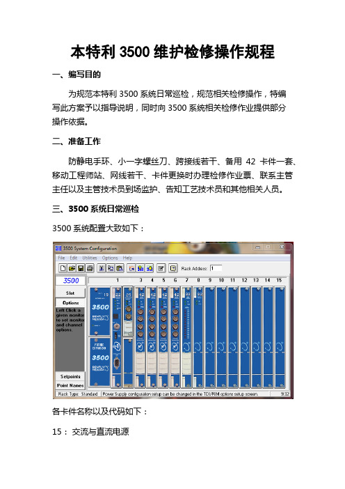
三、3500系统日常巡检3500系统配置大致如下:各卡件名称以及代码如下:15:交流与直流电源20:框架接口模块22M:瞬态数据接口25:增强型键相模块32:4通道继电器模块33:16通道继电器模块34:TMR继电器模块42M:振动监测模块45:位移监测模块50:转速表模块53:超速检测系统92:通讯网关模块日常巡检过程中主要查看各卡件模块状态指示灯,从而判断卡件状态,各卡件LED故障状态以及处理办法如下:1、当15模块(交流与直流电源)的“SUPPLY OK”灯熄灭时需检查以下项目:a、检查提供给电源输入模块的供电电压是否正确。
b、检查安装的电源输入模块类型与电源模块是否匹配(例如交流电源模块配置交流电源输入模块)。
c. 确定电源输入模块上的保险丝是否熔断;如果是,请更换保险丝。
保险丝熔断可能是由于电源输入模块上严重过压,或者3500 电源模块内出现故障。
d. 如果步骤1 到3 解决不了问题,则需要安装一个新的电源模块。
2、20卡状态指示灯以及处理办法3、22M卡状态指示灯以及处理办法4、25卡状态指示灯以及处理办法5、25卡状态指示灯以及处理办法6、42卡状态指示灯以及处理办法、7、50卡状态指示灯以及处理办法、8、92卡状态指示灯以及处理办法、四、3500系统基本操作1、使用网线连接3500机架①更改电脑IP地址,使其与机架IP在同一网段②使用双绞网线与机架连接③打开3500组态程序,点击Connect按钮,选择Network Connect如下图④在弹出的对话框中输入所连机架IP地址,点击Conncet按钮,完成连接⑤链接后画面如下,点击Upload form Rack按钮,将机架内的程序上传到电脑上,即可查看机架内组态。
OPTIX OSN3500智能光传输设备日常维护手册

ii
OptiX OSN 3500 智能光传输系统 维护手册 日常维护分册
目
录
插图目录
图 1-1 佩带防静电手腕图................................................................................................................2 图 2-1 风扇系统结构示意图............................................................................................................9 图 2-2 误码测试连接图................................................................................................................. 11
1-1
OptiX OSN 3500 智能光传输系统 维护手册 日常维护分册
1. 人身的伤害
警告: 光接口板激光器发送的激光为不可见的红外光, 激光在照射人眼时可能会对眼睛造 成永久性。
OptiX OSN 3500 使用的拉曼放大器 62COA 的发送光功率非常大,在对此单板进 行操作和维护时,请务必先关闭激光器,保证安全。 2. 设备的损坏 对于光接口板上未使用的光接口和尾纤上未使用的光接头,用防尘帽盖住。对于光 接口板上正在使用的光接口,当需要拔下连接在光接口上的尾纤时,用防尘帽盖住 光接口和与其连接的尾纤接头,起到防尘的作用。 请使用专用清洁工具和材料清洁光接口。清洗光接口时,要先将连接在板上的光纤 拔下来,再将光接口板拔出进行操作,避免带纤拔板和插板。 用尾纤对光口进行硬件环回测试时一定要加衰耗器, 以防接收光功率太强导致接收 光模块损坏。
3500 操作手册

SIMS Graseby 有限责任公司 Watford, 赫特福德县, 大不列颠联合王国,
WD2 4LG
电话 传真
(+44)(0)1923 246434 (+44)(0)1923 231595
英国注册,注册号:995550
ⅰ
1
麻醉注射泵 简介 小心和警告
2
首先感谢你选择 Graseby 3500 麻醉注射泵。这本仪器使用手册包含操作和保养你所购买的麻醉注射泵的所有重 要信息。为了完全熟悉该仪器的所有特征,请在使用前仔细阅读这本手册。
预先装充 Diprivan 的针管是专门用来注射药物‘Diprivan’(D)的
Graseby 3500
7
麻醉注射泵
美国及加拿大用户使用关注
美国和加拿大联邦法律规定该仪器只能由得到许可的或与之类似的医学营业者进行销售。
FDA 所需应用信息
应用在脑膜上请注意: 1. 该仪器可用于止痛剂的输入。 2. 注射根据导管大小和药物说明可分为短期或长期。 3. 使用指定用于脑膜给药的导管。 4. Y 连接点注射设定不能用于脑膜给药。 5. 该仪器只能注射在药品标签上声明可用于脑给药的止痛药。
Graseby 3500
目录(接上) Graseby 3500
麻醉注射泵
第五章
警报
页码 简介………………………………………………………………………………………………………………………5-1 紧急警报…………………………………………………………………………………………………………………5-2 柔和警报…………………………………………………………………………………………………………………5-9 静音警报……………………………………………………………………………………………………………… 5-12 TCI 警报 ……………………………………………………………………………………………………………… 5-16
本特利3500安装与调试

1传感器的安装与调试1.1轴承振动传感器探头的安装6个φ8 mm灵敏度为7.87 V/rnm的涡流探头分别装于1号、2号、3号轴承处。
每个轴承处安装两只互成90°,垂直于轴承,探头与水平方向的夹角为45°,分别测量X、Y方向上的振动。
一般涡流传感器,涡流影响范围约为传感器线圈直径的三倍,因此传感器对应的测量宽度应为传感器直径的三倍,而且在传感器空间24mm范围内不应有其它金属物存在,否则会带来误差。
安装间隙电压应为传感器输出特性曲线确定的线形中点位而定,φ8 mm灵敏度为7.87 V/mm的探头,安装间隙电压为-9.75 V或1.2 mm左右。
由于传感器线形电压范围大大超过测量范围,所以安装间隙允许有较大的偏差,只要保证测量范围在线形段内即可,但为了满足故障诊断和可靠性的需要,一般要求安装电压9.75土0.2 V。
1.2轴向位移、高低压差胀传感器的安装轴向位移测的是推力轴承相对汽缸的轴向位移,在机组运行过程中,使动静部件之间保持一定的轴向间隙,避免汽轮机内部转动部件和静止部件之间发生摩擦和碰撞。
两只轴向位移传感器探头安装在2号轴承处,分别装于甲乙两侧,探头朝向低压缸方向安装探头型号为7200型φ14mm探头,灵敏度为3.937V/mm,前臵器供电电压为-24V。
大轴相对于汽缸的设计零点为止推轴承靠在工作瓦面为大轴零位。
在安装轴向位移和低压差胀传感器前,首先要把大轴推到零位,然后按要求安装。
轴向位移的量程范围为-2 mm一+ 2 mm,安装电压-9.75土0.2 V沾化电厂汽轮机膨胀相对死点在2号轴承处,高压缸转子膨胀在以2号轴承处为相对死点向前箱方向膨胀,低压缸转子膨胀在以2轴承处为相对死点向发电机方向膨胀。
高低压差胀探头为不带前臵器φ25 mm涡流探头,灵敏度为0.8 V/ mm,因为高低压差胀都是朝着发电机方向安装,要使高低缸差胀测量范围均在线形范围之内,按照探头线性中点及量程范围- 2--10 mm定位。
lbp3500维修手册

Indicates an item requiring care to avoid combustion (fire).
Indicates an item prohibiting disassembly to avoid electric shocks or problems.
1.3 Product Specifications ................................................................................................................................1- 1 1.3.1 Specifications .......................................................................................................................................................... 1- 1
1.4 Name of Parts.............................................................................................................................................1- 3 1.4.1 External View........................................................................................................................................................... 1- 3 1.4.2 Cross Section .......................................................................................................................................................... 1- 4
Galaxy 3500全线产品用户手册

MGE Galaxy 3500 10-40 kVA 380/400/415 V 和 10-30 kVA 208/220 V 操作手册
i
单个系统和并联系统 . . . . . . . . . . . . . . . . . . . . . . . . . . . . . . . . . . . . . . 17
界面区 . . . . . . . . . . . . . . . . . . . . . . . . . . . . . . . . . . . . . . . . . . . . . . . . . . 2 显示界面 . . . . . . . . . . . . . . . . . . . . . . . . . . . . . . . . . . . . . . . . . . . . . . . . 2 菜单树 . . . . . . . . . . . . . . . . . . . . . . . . . . . . . . . . . . . . . . . . . . . . . . . . . . 3
本特利3500中文说明书

本特利3500中文说明书TSI系统调试基本知识本内容将围绕大多数电厂中广泛使用的美国本特利(BENTLY)公司生产的振动检测系统3500为模版,全面讲述系统安装、组态、调试过程及调试中常见问题的处理。
第一节 TSI系统硬件基本知识3500系统能提供连续、在线监测功能,适用于机械保护应用,并为早期识别机械故障提供重要的信息。
该系统高度模块化的设计主要包括:序号名称型号数量配置要求1.仪表框架3500/05 一套必须2.电源模块3500/15 一或两块必须3.接口模块3500/20 一块必须4.键相器模块3500/25 一或两块可选5.监测器模块3500/XX(42、45、53、50)一个或多块必须6.继电器模块3500/32 一个或多块可选7.三重冗余继电器模块3500/34 一个或多块可选8.通讯网关模块3500/92 一个或多块可选9.3500 框架组态软件必须见下图:系统的工作流程是:从现场取得的传感器输入信号提供给3500监测器框架内的监测器和键相位通道,数据被采集后,与报警点比较并从监测器框架送到一个地方或多个地方处理。
3500框架中模件的共同特征是带电插拔和内部、外部接线端子。
任何主模件(安装在3500框架前端)能够在系统供电状态中拆除和更换而不影响不相关模块的工作,如果框架有两个电源,插拔其中一块电源不会影响3500框架的工作。
外部端子使用多芯电缆(每个模块一根线)把输入\输出模块与终端连接起来,这些终端设备使得在紧密空间内把多条线与框架连接起来变的非常容易,内部端子则用于把传感器与输入\输出模块直接连接起来。
外部端子块一般不能与内部端子输入/输出模块一起使用。
1、3500/05系统框架3500框架用于安装所有的监测器模块和框架电源。
它为3500各个框架之间的互相通讯提供背板通讯,并为每个模块提供所要求的电源。
3500框架有两种尺寸:1 全尺寸框架——19英寸EIA框架,有14个可用模块插槽2 迷你型框架——12英寸框架,有7个可用模块插槽电源和框架接口模块必须安装于最左边的两个插槽中。
OptixOSN3500智能光传输设备日常维护手册

榆林神华能源有限责任公司Optix OSN3500智能光传输设备日常维护手册二O一O年十月目录第1章设备维护注意事项.......................................................................................................... 1-11.1 激光................................................................................................................................... 1-11.2 电气................................................................................................................................... 1-21.3 单板维护............................................................................................................................ 1-31.4 网管系统维护..................................................................................................................... 1-31.5 更改业务配置..................................................................................................................... 1-4第2章日常维护基本操作.......................................................................................................... 2-52.1 设备日常维护项目 ............................................................................................................. 2-52.2 设备维护基本操作 ............................................................................................................. 2-72.2.1 检查设备温度、湿度............................................................................................... 2-72.2.2 观察机柜指示灯 ...................................................................................................... 2-72.2.3 观察单板指示灯 ...................................................................................................... 2-82.2.4 检查设备声音告警................................................................................................... 2-82.2.5 检查和定期清理风扇............................................................................................... 2-92.2.6 检查公务电话........................................................................................................ 2-102.2.7 检查业务-测试误码............................................................................................. 2-112.3 运用网管进行设备维护的基本操作.................................................................................. 2-122.3.1 检查网元和单板状态............................................................................................. 2-122.3.2 检查告警 ............................................................................................................... 2-122.3.3 监视性能事件........................................................................................................ 2-132.3.4 检查保护倒换状态................................................................................................. 2-152.3.5 查询日志记录........................................................................................................ 2-162.3.6 检查ECC路由........................................................................................................ 2-162.3.7 同步网元时间........................................................................................................ 2-172.3.8 校验配置数据一致性............................................................................................. 2-172.3.9 备份网元配置数据................................................................................................. 2-182.3.10 备份和恢复T2000数据库 .................................................................................... 2-182.3.11 导出和导入配置脚本........................................................................................... 2-192.3.12 修改网管用户口令............................................................................................... 2-22插图目录图1-1 佩带防静电手腕图.................................................................................................. 1-2图2-1 风扇系统结构示意图.............................................................................................. 2-9图2-2 误码测试连接图 ................................................................................................... 2-11第1章设备维护注意事项本章介绍了在设备维护过程中需要注意的安全事项。
华为3500操作手册 装帧

HUAWEI1. 入门2. 端口3. VLAN4. 网络协议5. 路由协议6. 组播协议7. QoS/ACL8. 安全9. STP10. 集中管理11. 可靠性12. 系统管理13. 自动侦测14. 附录Quidway S3500系列以太网交换机操作手册Quidway S3500系列以太网交换机操作手册资料版本T1-081697-20050610-C-1.07BOM 编码31160997华为技术有限公司为客户提供全方位的技术支持通过华为技术有限公司代理商购买产品的用户请直接与销售代理商联系直接向华为技术有限公司购买产品的用户可与就近的华为办事处或用户服务中心联系也可直接与公司总部联系华为技术有限公司地址深圳市龙岗区坂田华为总部办公楼邮编518129网址声明Copyright ©2005华为技术有限公司版权所有保留一切权利非经本公司书面许可任何单位和个人不得擅自摘抄复制本书内容的部分或全部并不得以任何形式传播®HUAWEI®华为®C&C08®EAST8000®HONET®®视点®ViewPoint®INtess®ETS®DMC®TELLIN®InfoLink®Netkey®Quidway®SYNLOCK®Radium®雷霆®M900/M1800®TELESIGHT®Quidview®Musa®视点通®Airbridge®Tellwin®Inmedia®VRP®DOPRA®iTELLIN®HUAWEI OptiX®C&C08iNET®NETENGINE™OptiX™iSite™U-SYS™iMUSE™OpenEye™Lansway™SmartAX™边际网™infoX™TopEng™均为华为技术有限公司的商标对于本手册中出现的其它商标由各自的所有人拥有由于产品版本升级或其它原因本手册内容会不定期进行更新除非另有约定本手册仅作为使用指导本手册中的所有陈述信息和建议不构成任何明示或暗示的担保前言版本说明本手册对应产品版本为S3526-0025/S3526EF-S3526C-0035/S3528-S3552-0017相关手册Quidway S3500系列以太网交换机主要手册及用途如下手册名称用途Quidway S3526以太网交换机安装手册介绍了S3526以太网交换机的安装过程交换机的启动软硬件维护与监控等内容Quidway S3526E以太网交换机安装手册介绍了S3526E以太网交换机的安装过程交换机的启动软硬件维护与监控等内容Quidway S3526 FM/FS以太网交换机安装手册介绍了S3526 FM/FS以太网交换机的安装过程交换机的启动软硬件维护与监控等内容Quidway S3526C/S3526EFM/S3526E FS以太网交换机安装手册介绍了S3526C/S3526E FM/S3526E FS以太网交换机的安装过程交换机的启动软硬件维护与监控等内容Quidway S3552系列以太网交换机安装手册介绍了S3552系列以太网交换机的安装过程交换机的启动软硬件维护与监控等内容Quidway S3528系列以太网交换机安装手册介绍了S3528系列以太网交换机的安装过程交换机的启动软硬件维护与监控等内容Quidway S3552F以太网交换机安装手册介绍了S3552F以太网交换机的安装过程交换机的启动软硬件维护与监控等内容Quidway S3500系列以太网交换机操作手册介绍了入门端口VLAN网络协议路由协议组播协议QoS/ACL安全STP集中管理可靠性系统管理自动侦测等模块的内容Quidway S3500系列以太网交换机命令手册包括入门端口VLAN网络协议路由协议组播协议QoS/ACL安全STP集中管理可靠性系统管理自动侦测等模块的命令解释本书简介Quidway S3500系列以太网交换机操作手册章节安排如下z入门主要描述访问以太网交换机的方式和步骤z端口主要介绍如何配置以太网端口和端口汇聚配置z VLAN主要介绍VLAN isolate-user-vlan GARP GVRP的相关配置z网络协议主要介绍网络协议配置过程包括IP地址配置ARP配置DHCP 配置访问管理配置及IP性能配置z路由协议主要介绍路由协议配置过程包括静态路由配置RIP配置OSPF 配置BGP配置和路由策略配置z组播协议主要介绍GMRP IGMP snooping IGMP PIM-DM PIM-SM的配置z QoS/ACL主要介绍QoS/ACL的相关配置z安全主要介绍以太网交换机安全相关配置包括802.1x AAA RADIUS配置z STP主要介绍以太网交换机上生成树协议的相关配置z集中管理主要介绍以太网交换机集中管理的相关配置包括堆叠配置和HGMP 配置z可靠性主要介绍VRRP配置z系统管理主要介绍以太网交换机的管理和维护的相关配置包括文件管理系统维护网络管理配置等z自动侦测主要介绍自动侦测原理及其应用的相关配置z附录缩略语表读者对象本书适合下列人员阅读z网络工程师z网络管理人员z具备网络基础知识的用户本书约定1. 通用格式约定格式意义宋体正文采用宋体表示黑体除一级标题采用宋体加粗以外其余各级标题均采用黑体楷体警告提示等内容一律用楷体并且在内容前后增加线条与正文隔离格式意义Terminal Display格式自定义的Terminal Display格式英文Courier New中文宋体文字大小8.5表示屏幕输出信息此外屏幕输出信息中夹杂的用户从终端输入的信息采用加粗字体表示2. 命令行格式约定格式意义粗体命令行关键字命令中保持不变必须照输的部分采用加粗字体表示斜体命令行参数命令中必须由实际值进行替代的部分采用斜体表示[ ] 表示用[ ]括起来的部分在命令配置时是可选的{ x | y | ... }表示从两个或多个选项中选取一个[ x | y | ... ]表示从两个或多个选项中选取一个或者不选{ x | y | ... } *表示从两个或多个选项中选取多个最少选取一个最多选取所有选项[ x | y | ... ] *表示从两个或多个选项中选取多个或者不选#由#号开始的行表示为注释行3. 键盘操作约定格式意义加尖括号的字符表示键名如<Enter><Tab><Backspace><a>等分别表示回车制表退格小写字母a<键1 + 键2> 表示在键盘上同时按下几个键如<Ctrl+Alt+A>表示同时按下Ctrl Alt A这三个键<键1键2> 表示先按第一键释放再按第二键如<Alt F>表示先按<Alt>键释放后再按<F>键4. 鼠标操作约定格式意义单击快速按下并释放鼠标的一个按钮双击连续两次快速按下并释放鼠标的一个按钮拖动按住鼠标的一个按钮不放移动鼠标5. 各类标志本书还采用各种醒目标志来表示在操作过程中应该特别注意的地方这些标志的意义如下小心注意警告危险提醒操作中应注意的事项说明提示窍门思考对操作内容的描述进行必要的补充和说明。
3500系统架架系统说明书
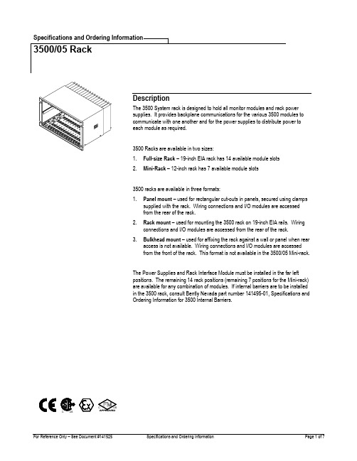
1. Full-size Rack – 19-inch EIA rack has 14 available module slots2. Mini-Rack – 12-inch rack has 7 available module slots3500 racks are available in three formats:1. Panel mount – used for rectangular cut-outs in panels, secured using clampssupplied with the rack. Wiring connections and I/O modules are accessedfrom the rear of the rack.2. Rack mount – used for mounting the 3500 rack on 19-inch EIA rails. Wiringconnections and I/O modules are accessed from the rear of the rack.3. Bulkhead mount – used for affixing the rack against a wall or panel when rearaccess is not available. Wiring connections and I/O modules are accessedfrom the front of the rack. This format is not available in the 3500/05 Mini-rack. The Power Supplies and Rack Interface Module must be installed in the far left positions. The remaining 14 rack positions (remaining 7 positions for the Mini-rack) are available for any combination of modules. If internal barriers are to be installed in the 3500 rack, consult Bently Nevada part number 141495-01, Specifications and Ordering Information for 3500 Internal Barriers.SpecificationsHazardous Area ApprovalsCSA/C/USRefer to the data sheet of applicablemonitor being inserted into the rack.CE Mark DirectivesBN 136669Bently Nevada Low Voltage Directive BN 134036Bently Nevada EMC DirectiveEN61000-6-4Radiated EmissionsEN 55011, Class AConducted EmissionsEN 55011, Class AEN61000-6-2Electrostatic DischargeEN 61000-4-2, Criteria BRadiated RFIEN61000-4-3, Criteria AConducted SusceptibilityEN61000-4-3, Criteria AElectrical Fast TransientEN 61000-4-4, Criteria BSurge CapabilityEN 61000-4-5, Criteria BMagnetic FieldEN 61000-4-8, Criteria APower Supply DipEN 61000-4-11, Criteria BRadio FrequencyEN61000-4-6, Criteria A Ordering ConsiderationsRacks with Internal Barriers installed require that a 3500/04-01 Internal Barrier Earthing Module isinstalled to provide the connection of the IS Earth tothe 3500/05 rack. This module requires a dedicatedrack position.The 3500/93 System Display A01 System Face Mount option is incompatible with the 3500/05 Mini-rack.The 3500/05 Mini-rack is not available in the Bulkhead mount option. The 3500/06 Weatherproof housing is not compatible with the 3500/05 Bulkhead Mount option.When using a 3500 Mini-rack in an EIA rack, a 144863-01 19-inch EIA Adapter Panel is required.The 3500 Mini-rack requires 3500/01 Software, version2.70 or later.Ordering InformationRack Ordering Information3500/05-AXX-BXX-CXX-DXX-EXXA: Rack Size0 119-inch Rack (14 Module Slots)0 212-inch Mini-Rack (7 ModuleSlots)B: Mounting Options0 1Panel Mount Option, Full-SizeRack0 2Rack Mount Option, Full-SizeRack (mounts to19-inch EIARack)0 3Bulkhead Mount Option (Notavailable in Mini-Rack)0 4Panel Mount Option, Mini-Rack0 5Rack Mount Option, Mini-Rack C:Agency Approval Option0 0 None0 1CSA - C - USD: Reserved0 0 NoneE:European Compliance Option0 0 None0 1 CESparesPart NumberDescriptionHalf-height ModuleAdapterOrder the following125388-01Half-height Module Internal Chassis(Qty 1)125565-01Half-height Module Card Guide (Qty 1) 04300111Screws for Half-height ModuleInternal Chassis (Qty 3)Power SupplyBlank Cover KitOrder the following131150-01Power Supply Blank Front Panel (Qty1)128085-01Power Supply Input Connector Cover(Qty 1)04310251Screw for Power Supply Input Cover(Qty 2)Full-height BlankMonitor Cover KitOrder as 130768-01 which includes 130944-01Full-height Monitor Blank Front Panel(Qty 1)128031-01I/O Module Cover (Qty 1)04310251Screw for I/O Module Cover (Qty 2) Half-height BlankMonitor Covor KitOrder the Following131151-01Half-height Blank Front Panel Cover(Qty 1)Misc Components00517016TMR/SIM jumper (installed on the 3500backplane)144863-01Adapter Panel, Mini-rack, 19-inch 129766-01Rack Installation and MaintenanceManual130432-01Field Wiring DiagramsFigures and Tables1. 10.470 inches (265.94 mm).2. 19.000 inches (482.60 mm).3. 17.400 inches (441.96 mm).4. 9.700 inches (246.38 mm).5. 13.750 inches (349.25 mm), 16.650 inches (422.91 mm) if used with internal barriersFig. 1. 3500 Full-Size rack mounting dimensions for the Rack and Panel MountConfiguration1. 7.80 +/- 0.06 inches (452.1 +/- 1.5 mm).2. 0.125 inches (3.2 mm) radius, maximum.3. 9.90 +/- 0.60 inches (251.5 +/- 1.5 mm).Fig. 2. 3500 Full-Size Rack Recommended Panel Cutout2. 12.000 inches (304.80 mm).3. 10.400 inches (264.16 mm).4. 9.700 inches (246.38 mm).5. 13.750 inches (349.25 mm), 16.650 inches (422.91 mm) if used with internal barriersFig. 3. 3500 Mini-rack mounting dimensions for the Panel Mount Configuration1.2.3.2. AdapterPanel3. Standard 19-inch EIA rackFig. 5. 3500 Mini-rack and Adapter Panel mounting to a 19-inch EIA Rack1. 19.000 inches (482.60 mm).2. 18.094 inches (459.59 mm).3. 5.250 inches (133.35 mm).4. 7.500 inches (190.50 mm).5. 5.250 inches (133.35 mm).6. 20.970 inches (532.64 mm).7. 10.500 inches (266.70 mm).Fig. 6. Dimensions of a Bulkhead Mount 3500 rack1999 Bently Nevada LLC。
Enterprise3500服务器安装手册

Sun Enterprise3500SystemInstallation GuideA Sun Microsystems,Inc.Business901San Antonio RoadPalo Alto,,CA94303-4900Part No:805-2629-10Revision A,April1998USA650960-1300fax650969-9131Sun Enterprise3500SystemInstallation GuidePart No:805-2629-10Revision A,April1998Copyright1998Sun Microsystems,Inc.901San Antonio Road,Palo Alto,California94303-4900U.S.A.All rights reserved.All rights reserved.This product or document is protected by copyright and distributed under licenses restricting its use,copying, distribution,and decompilation.No part of this product or document may be reproduced in any form by any means without prior written authorization of Sun and its licensors,if any.Portions of this product may be derived from the UNIX®system,licensed from Novell,Inc.,and from the Berkeley4.3BSD system, licensed from the University of California.UNIX is a registered trademark in the United States and in other countries and is exclusively licensed by X/Open Company Ltd.Third-party software,including font technology in this product,is protected by copyright and licensed from Sun’s suppliers.RESTRICTED RIGHTS:Use,duplication,or disclosure by the ernment is subject to restrictions of FAR 52.227-14(g)(2)(6/87)and FAR52.227-19(6/87),or DFAR252.227-7015(b)(6/95)and DFAR227.7202-3(a).Sun,Sun Microsystems,the Sun logo,and Solaris are trademarks or registered trademarks of Sun Microsystems,Inc.in the United States and in other countries.All SPARC trademarks are used under license and are trademarks or registered trademarks of SPARC International, Inc.in the United States and in other countries.Products bearing SPARC trademarks are based upon an architecture developed by Sun Microsystems,Inc.The OPEN LOOK®and Sun TM Graphical User Interfaces were developed by Sun Microsystems,Inc.for its users and licensees.Sun acknowledges the pioneering efforts of Xerox Corporation in researching and developing the concept of visual or graphical user interfaces for the computer industry.Sun holds a nonexclusive license from Xerox to the Xerox Graphical User Interface,which license also covers Sun’s licensees who implement OPEN LOOK GUIs and otherwise comply with Sun’s written license agreements.THIS PUBLICATION IS PROVIDED“AS IS”WITHOUT WARRANTY OF ANY KIND,EITHER EXPRESS OR IMPLIED,INCLUDING, BUT NOT LIMITED TO,THE IMPLIED WARRANTIES OF MERCHANTABILITY,FITNESS FOR A PARTICULAR PURPOSE,ORNON-INFRINGEMENT.Copyright1998Sun Microsystems,Inc.,901San Antonio Road,Palo Alto,Californie94303-4900U.S.A.Tous droits réservés.Ce produit ou document est protégépar un copyright et distribuéavec des licences qui en restreignent l’utilisation,la copie et ladécompilation.Aucune partie de ce produit ou de sa documentation associée ne peutêtre reproduite sous aucune forme,par quelque moyen que ce soit,sans l’autorisation préalable etécrite de Sun et de ses bailleurs de licence,s’il y en a.Des parties de ce produit pourrontêtre derivées du système UNIX®licenciépar Novell,Inc.et du système Berkeley4.3BSD licenciépar l’Universitéde Californie.UNIX est une marque enregistrée aux Etats-Unis et dans d’autres pays,et licenciée exclusivement par X/Open Company Ltd.Le logiciel détenu par des tiers,et qui comprend la technologie relative aux polices de caractères,est protégépar un copyright et licenciépar des fournisseurs de Sun.Sun,Sun Microsystems,le logo Sun,et Solaris sont des marques déposées ou enregistrées de Sun Microsystems,Inc.aux Etats-Unis et dans d’autres pays.Toutes les marques SPARC,utilisées sous licence,sont des marques déposées ou enregistrées de SPARC International, Inc.aux Etats-Unis et dans d’autres pays.Les produits portant les marques SPARC sont basés sur une architecture développée par Sun Microsystems,Inc.Les utilisateurs d’interfaces graphiques OPEN LOOK®et Sun TM ontétédéveloppés de Sun Microsystems,Inc.pour ses utilisateurs et licenciés.Sun reconnaît les efforts de pionniers de Xerox Corporation pour la recherche et le développement du concept des interfacesd’utilisation visuelle ou graphique pour l’industrie de l’informatique.Sun détient une licence non exclusive de Xerox sur l’interfaced’utilisation graphique,cette licence couvrant aussi les licenciés de Sun qui mettent en place les utilisateurs d’interfaces graphiques OPEN LOOK et qui en outre se conforment aux licencesécrites de Sun.CETTE PUBLICATION EST FOURNIE"EN L’ETAT"SANS GARANTIE D’AUCUNE SORTE,NI EXPRESSE NI IMPLICITE,Y COMPRIS, ET SANS QUE CETTE LISTE NE SOIT LIMITATIVE,DES GARANTIES CONCERNANT LA VALEUR MARCHANDE,L’APTITUDE DES PRODUITS A REPONDRE A UNE UTILISATION PARTICULIERE OU LE FAIT QU’ILS NE SOIENT PAS CONTREFAISANTS DE PRODUITS DE TIERS.PleaseRecycleContentsPreface vi1.Preparing for Installation1Unpacking and Preparing the System2Shipping and Storing the System3Preparing the Electrical Circuits3Preparing the Air Conditioning3Preparing the Ethernet Network4Preparing the Area5Using the User Naming Area62.Cabling the System9Preparing the System for Cabling9Installing the Fiber Cable Organizer9Connecting the Power Cord11Connecting the Network Cable to the System14Connecting the System to the Network15Connecting an ASCII Terminal18Connecting the Fiber Cable to the I/O+Board20Connecting the Fiber Cable to the Interface Board and the I/O+Board21 Wrapping the Fiber Cable on the Organizer22Contents ivConnecting External SCSI Devices253.Powering the System On and Off27Using JumpStart Automatic Installation27Powering On the System28Reading Boot Messages31Interpreting Status LED Patterns32Powering Off the System334.Software35Operating System Software and Patches35Solaris2.6-Patch105375-0435Solstice SyMON Software35Dynamic Reconfiguration36CPU Over Temperature Safeguard(COS)36A.Regulatory Agency Compliance Statements37FCC,DOC,and VCCI Class Notices37FCC Class A Notice37DOC Class A Notice–Avis DOC,Classe A38VCCI39Declaration of Conformity40Index41v Sun Enterprise3500System Installation Guide♦Revision A,April1998PrefaceThe Sun Enterprise3500System Installation Guide provides installation instructions for the factory-configured5-slot system.These instructions are for an experienced system administrator with networking knowledge.UNIX CommandsThis document may not contain information on basic UNIX®commands and procedures such as shutting down the system,booting the system,and configuring devices.See one or more of the following for this information:4Solaris2.x Handbook for SMCC Peripherals,which contains Solaris TM2.x software commands4AnswerBook TM online documentation for the Solaris2.x software environment4Other software documentation that you received with your system Typographic ConventionsPreface viTABLE P–1Typographic ConventionsTypeface orSymbol Meaning ExamplesAaBbCc123The names of commands,files,anddirectories;on-screen computeroutput.Edit your.loginfile. Use ls-a to list allfiles. %You have mail.AaBbCc123What you type,when contrastedwith on-screen computer output.%suPassword:AaBbCc123Book titles,new words or terms,words to be emphasized.Command-line variable;replacewith a real name or value.Read Chapter6in the User’s Guide. These are called class options.You must be root to do this.To delete afile,type rmfilename.Shell PromptsTABLE P–2Shell PromptsShell PromptC shell machine_name%C shell superuser machine_name#Bourne shell and Korn shell$Bourne shell and Korn shell superuser#vii Sun Enterprise3500System Installation Guide♦Revision A,April1998Related DocumentationTABLE P–3Related DocumentsApplication Title Part Number Service Sun Enterprise3500System Reference Manual805-2630 Software SMCC SP ARC Hardware Platform Guide802-5341 Solstice SyMON User’s Guide802-5355805-3530 Dynamic Reconfiguration User’s Guide for Sun EnterpriseSystems805-4009 Options Sun Enterprise Expansion Cabinet Installation and ServiceManualSun Enterprise6/5/4/3x00Board Installation Guide805-40074Mbyte UltraSP ARC II Installation Guide805-1150Sun Enterprise6/5/4/3x00Systems SIMM Installation Guide802-5032805-2704 SBus+and Graphics+I/O Boards(100MB/sec FibreChannels)for Sun Enterprise6/5/4/3x00SystemsPCI+I/O Board Installation and Component Replacement for805-1372 Sun Enterprise6/5/4/3x00Systems802-5033 Sun Enterprise Peripheral Power Supply/AC InstallationGuide805-4012 Sun Enterprise3500Auxiliary Peripheral Power SupplyInstallation GuideSun Enterprise3500Fiber Cable Organizer Installation Guide805-4010Sun Enterprise3500Interface Board Installation Guide805-4011Sun Enterprise Peripheral Power Supply Installation Guide802-5033802-6244 Sun Enterprise Power/Cooling Module(PCM)InstallationGuideviiiOrdering Sun DocumentsSunDocsSM is a distribution program for Sun Microsystems technicaldocumentation.Contact SunExpress for easy ordering and quick delivery.You canfind a listing of available Sun documentation on the World Wide Web.TABLE P–4SunExpress Contact InformationCountry Telephone FaxBelgium02-720-09-0902-725-88-50Canada1-800-873-78691-800-944-0661France0800-90-61-570800-90-61-58Germany01-30-81-61-9101-30-81-61-92Holland06-022-34-4506-022-34-46Japan0120-33-90960120-33-9097Luxembourg32-2-720-09-0932-2-725-88-50Sweden020-79-57-26020-79-57-27Switzerland0800-55-19-260800-55-19-27United Kingdom0800-89-88-880800-89-88-87United States1-800-873-78691-800-944-0661World Wide Web:/sunexpress/Sun Documentation on the WebThe web site enables you to access Sun technical documentation onthe World Wide Web.You can browse the archive or search for aspecific book title or subject at .ix Sun Enterprise3500System Installation Guide♦Revision A,April1998Sun Welcomes Your CommentsWe are interested in improving our documentation and welcome your comments and suggestions.You can email your comments to us at smcc-docs@.Please include the part number of your document in the subject line of your email. Notes,Cautions,and WarningsCaution-This equipment contains lethal voltage.Accidental contact with centerplane,card cage,and drive areas can result in serious injury or death.Caution-Improper handling by unqualified personnel can cause serious damage to this equipment.Unqualified personnel who tamper with this equipment may be held liable for any resultant damage to the equipment.Individuals who remove any outer panels or open covers to access this equipment must observe all safety precautions and ensure compliance with skill level requirements,certification,and all applicable local and national laws.Procedures contained in this document must be performed by qualifiedservice-trained maintenance providers.Note-Before you begin,carefully read each of the procedures in this manual.If you have not performed similar operations on comparable equipment,do not attempt to perform these procedures.xxi Sun Enterprise3500System Installation Guide♦Revision A,April1998CHAPTER1Preparing for InstallationThis chapter describes how to prepare your site for the Sun Enterprise3500serversystem.The tasks for installing the system are:Unpacking the serverPreparing the sitePreparing the serverCablingPowering onUsing the softwareNote-For information about physical specifications,electrical specifications,andenvironmental requirements,refer to Appendix A“Specifications,”in the SunEnterprise3500System Reference Manual(part number805-2630).1Figure1–1Enterprise3500SystemUnpacking and Preparing the SystemNote-Inspect all shipping cartons for evidence of physical damage.If a shippingcarton is damaged,request that the carrier’s agent be present when the carton isopened.Keep all contents and packing material for the agent’s inspection.If the system is already unpacked,go to“Preparing the Electrical Circuits”on page3.Caution-The system can weigh up to185lbs(84kg).To prevent personal injury,two people are needed to lift the system safely.The rear support bracket is designedto support the system weight only when the system is stationary,on aflat surface.Do not attempt to lift the system by grasping the support bracket.Tools4#2Phillips screwdriver4System key for front door and key switch(packed in a bag in the accessory box) 2Sun Enterprise3500System Installation Guide♦Revision A,April1998Follow the graphical instructions on the shipping container to remove the system from the container.Remove the system key(for front door and key switch),and power cord from the shipping container.These are needed to power on the system. Note-Any unpacking instructions printed on the outside of the shipping carton take precedence over information in this section.Shipping and Storing the SystemSave the original shipping containers and packing materials in case you need to store or ship your system.If you cannot store the shipping materials,recycle or dispose of the materials properly.Consult your local recycling authority for information.Preparing the Electrical CircuitsIn planning where to place your equipment,remember that each of the following items requires access(by way of a separate power cord)to a power outlet:4Enterprise3500system4External peripherals4Monitor used for diagnosticsThe Enterprise3500system uses nominal input voltages of100-120VAC or200-220 VAC.Sun products are designed to work with single-phase power systems having a grounded neutral conductor.To reduce the risk of electrical shock,do not plug Sun products into another type of power source.Contact your facilities manager or a qualified electrician if you are unsure what type of power is supplied to your building.Preparing the Air ConditioningFor the most reliable system operation:4The room should have sufficient air conditioning capacity to support the cooling needs of the entire system.Preparing for Installation34The air conditioning system should have controls that prevent excessivetemperature changes.Refer to Appendix A“Specifications,”in the Sun Enterprise3500System ReferenceManual for environmental information.Preparing the Ethernet NetworkThe Enterprise3500system follows the IEEE standard for10/100BASE-T Ethernet(twisted-pair)or MII(Media Independent Interface).Twisted-pair cables used with Sun Microsystems products have RJ-45connectors thatresemble the smaller RJ-11connectors used for modular telephone cables.Fortwisted-pair cable length,see Table2–1.A MII to AUI converter cable,available from Sun,enables the10/100Mbps Ethernetinterface to run over10Mbps coaxial Ethernet networks.Other MII Ethernetconnectivity products are available from third parties.Figure1–2and Figure1–3illustrate types of network cables and possibleimplementations of10/100BASE-T Ethernet.Set up the network using Sun or third-party components.To obtain the best results,read any applicable manufacturer instructions.Be aware that Sun Microsystemscannot guarantee the performance of any components that are not purchased fromSun.Figure1–2Types of Network Cables Used4Sun Enterprise3500System Installation Guide♦Revision A,April1998Figure1–3Example of10/100BASE-T(Twisted-Pair)EthernetNote-Multiplexer boxes require a transceiver when used with the Ethernet applications described in this manual.Although these transceivers are compatible with Sun equipment,Sun Microsystems does not guarantee the performance of any component that was not purchased from Sun.Many transceivers are compatible with both level-1and level-2Ethernet.To operate these transceivers with Sun equipment,set the device for level-2operation following the manufacturer’s instructions.Sun equipment conforms to the Ethernet10/100BASE-T standard,which states that the10/100BASE-T Link Integrity Test function should always be enabled on both the host and the hub.If you have problems verifying connection between Sun equipment and your hub,verify that your hub also has the link test function enabled.Refer to “Failure of Network Communications”in the Sun Enterprise3500System Reference Manual(part number805-2630),and refer to the manual provided with your hub. Preparing the AreaUse the following guidelines to prepare a location for your server.4The server unit requires approximately1.5feet(47cm)of space in the front and rear for access by service personnel(Figure1–4).Preparing for Installation54A minimum space of6inches(16cm)is required on both sides of the server to afford adequate airflow.Caution-To avoid exhaust air recirculation,do not put systems or peripherals nextto each other,side by side.4Keep power and interface cables clear of foot traffic.Route cables inside walls, under thefloor,through the ceiling,or in protective channels.Route interfacecables away from motors and other sources of magnetic or radio frequencyinterference.Figure1–4Enterprise3500Server Access Areas—Top ViewUsing the User Naming AreaTo display the name of the server,IP address,owner,or other important informationon the front of the machine:1.Remove the front bezel.Refer to“Preparing for Service”in the Sun Enterprise3500System ReferenceManual(see“Front Bezel”).2.Snap out the narrow transparent window.From the rear side of the bezel,gently squeeze the top and bottom edges togetheras you simultaneously push the transparent window out through the front of thebezel.6Sun Enterprise3500System Installation Guide♦Revision A,April19983.Choose the information that will appear on the label.Common items include the name of the server,IP address,name and contact information for the system administrator,and the group of users that the machine services.e the colored paper provided with the system to make a label.The available area for the paper label is12mm x150mm(0.5in x5.9in).Print or write the desired information in an area this size and cut the label tofit thetransparent window.5.Place the paper label inside the window,and snap the window back in placefrom the front side of the bezel.Preparing for Installation78Sun Enterprise3500System Installation Guide♦Revision A,April1998CHAPTER2Cabling the SystemThis chapter contains instructions for installing thefiber cable organizer,cabling thesystem,and connecting the power cord to the AC power supply.Preparing the System for CablingMake sure the server is in an area that allows access to both the front and rear of thechassis.This site should conform to site preparation guidelines and specificationscovered in Chapter1.Installing the Fiber Cable OrganizerUse thefiber cable organizer to route thefiber optic cable to connect the interfaceboard and the I/O+board.A2-meter cable is required when utilizing the internalFC-AL disk drives.The cable organizer can help prevent damage to thefiber opticcable by helping ensure the1.0inch minimum bend radius rule is observed.Thefiber cable organizer kit includes two organizer sections and one screw.To installthe cable organizer:1.Remove the screw securing the power cord retainer clip to the support bracketat the rear of the system.92.Orient one of thefiber cable organizer sections with the spool facing towardyou.Set the hooks on the back of the organizer into the corresponding cutoutson the right side of the support bracket.The top of the brace should beflush with the top of the support bracket.Theorganizer will extend below the bracket.See Figure2–1.3.Secure the organizer by pushing it outward along the support bracket until thesnap at the rear of the organizer clicks audibly into place.4.Install the left spool brace by repeating step2and step3.ing the screw included in the kit,fasten the spool braces to the supportbracket through the center front cut out formed when both braces are in place.6.Remount the retainer clip through the hex nut at the notch on the side of theorganizer.Set the retainer clip screw into the hex nut.7.To wrap the2-meterfiber cable around the organizer spools to interconnect theinterface board and the I/O+board for FC-AL disks,see“Wrapping the FiberCable on the Organizer”on page22.10Sun Enterprise3500System Installation Guide♦Revision A,April1998Figure2–1Fiber Cable Organizer Mounted on Support BracketConnecting the Power Corde the key provided with your system to unlock and open the Enterprise3500system front door.2.Locate the system key switch in the upper right corner,insert the key provided,and turn the key switch to the Standby position.See Figure2–2.Cabling the System11Figure2–2Key Switch Standby Position3.T urn the AC power switch to Off.This switch is at the rear of the system,on the peripheral power supply/AC(PPS/AC)that is installed in the far left corner(Figure2–3).4.Connect the female end of the power cord into the AC connector.This connector is at the rear of the system,on the PPS/AC,just below the ACpower switch(Figure2–3).5.Route the power cord through the power cord retainer clip.In Step6on page10of“Installing the Fiber Cable Organizer”on page9,youreattached the plastic clip to the cable organizer that you mounted on the rearsupport bracket(Figure2–3).e a Phillips screwdriver to open the plastic retainer clip.Remove the screw.b.Place the power cord inside the open retainer clip and replace the screw toclose the clip.12Sun Enterprise3500System Installation Guide♦Revision A,April19986.Connect the male end of the power cord into a grounded outlet.The outlet must be a100-120or220-240VAC15A circuit.Figure2–3AC Power Switch,AC Connector,and Retainer ClipCaution-Do NOT turn on power to the unit yet.Doing so can cause system damage to occur.See the next sections to connect the network cable to the system,and to connect the system to the network.Cabling the System13Connecting the Network Cable to theSystemThe locations specified in the following instructions assume the use of twisted-pair10BASE-T or100BASE-T Ethernet.1.Locate the network cable.Figure2–4shows the twisted-pair Ethernet network cable.Figure2–4Network Cable2.Connect one end of the network cable into the RJ-45twisted-pair network port.For10/100BASE-T Ethernet,the default interface port is the onboard connectoron the I/O+board in slot1(Figure2–5).14Sun Enterprise3500System Installation Guide♦Revision A,April1998Figure2–510/100BASE-T Ethernet ConnectionConnecting the System to the Network1.Connect the network cable to a twisted-pair-to-transceiver interface box.2.Connect the interface box with an appropriate cable to a network transceiver.Figure2–6shows a typical arrangement for connecting the system to an Ethernet network.3.For Ethernet cables,determine if the cable has N-type screw-on connectors atthe ends.Cabling the System154If the Ethernet cable lacks N-type connectors at the ends,use a“vampire”tap to connect the cable to the transceiver(Figure2–6).To connect the cable to thetransceiver,use instructions provided with the vampire tap.4If the Ethernet cable has N-type connectors,connect the Ethernet cable to the transceiver:a.Screw the Ethernet coaxial cable into one of the round screw-on typeconnectors on the transceiver.Use either one of the transceiver connectors.b.Screw the other Ethernet coaxial cable into the other round screw-on typeconnector on the transceiver.4.Determine if a terminator should be installed.Table2–1lists the cablinglimitations for Ethernet.5.If termination is required,install a50-ohm terminator in the unused transceiverN connector or at the end of the coaxial e a female double N-typeconnector.Figure2–6shows the elements used in the installation process.Figure2–6Connecting Twisted Pair Ethernet to N-type Coaxial CableTable2–1lists the cabling limitations for Ethernet.16Sun Enterprise3500System Installation Guide♦Revision A,April1998TABLE2–1Ethernet Cabling Limitations for N-type Coaxial CableCable Segment Length in MetersAllowed contiguous length of cable segments23.470.2117.0500.0(1)Distance between transceivers(multiples-of) 2.5(2)Minimum length of Ethernet coaxial cable segments23.4Maximum length of transceiver“drop”cable50.0Minimum length of twisted pair cable no minimumMaximum length of twisted pair cable110Note-(1)Finite lengths(as constrained by transmission line phenomena).Minimum length=23.4M;maximum=500M.If cable falls shorter than one of these values,add cable to achieve next-highest value.(2)Transceivers are placed at intervals of2.5meters,or multiples of2.5metersalong the Ethernet cable.Example:transceivers are connected2.5meters apart, not2.0meters.Example:transceivers are connected15meters apart(6multiples of2.5meters),not14.0meters.Figure2–7shows an example of a typical network setup.The Enterprise3500 system can be any server shown in thisfigure.Cabling the System17Figure2–7Ethernet Cabling Length—Example Using N-type CableNote-Sun equipment conforms to the Ethernet10/100BASE-T standard,whichstates that the10/100BASE-T Link Integrity Test function should always beenabled on both the host and the hub.If you have problems verifying connectionbetween Sun equipment and your hub,verify that your hub also has the link testfunction enabled.Refer to Section8.6.1,“Failure of Network Communications,”inthe Sun Enterprise3500System Reference Manual(part number805-2630),andrefer to the manual provided with your hub for more information about the LinkIntegrity Test function.6.If all cables are connected,power on the system.Connecting an ASCII TerminalAn ASCII terminal(or workstation)can be attached to the server to displaydiagnostic messages produced by thefirmware(power-on self-test/POST orOpenBoot TM PROM/OBP)program.A terminal is not required for normal serveroperations,so it may be necessary to locate a terminal to connect to the server.1.Connect the terminal cable into serial port A on the clock+board.See Figure2–8.18Sun Enterprise3500System Installation Guide♦Revision A,April1998Figure2–8Clock+Board2.Connect the terminal power cord into an AC wall outlet.3.Configure the ASCII terminal as follows:49600bps41stop bit48data bits4Parity off4Full duplexRefer to the instruction manual shipped with the terminal for specificconfiguration instructions.Note-The setup parameters listed in Step3on page19may differ from the setup at the customer site.These parameters can be changed in the NVRAM(nonvolatile random access memory).Refer to the set-defaults and printenvcommands in the OpenBoot Command Reference manual,part number802-3242.Cabling the System19Connecting the Fiber Cable to the I/O+Board1.Remove the two plastic caps that cover the cable connector on the GBICmodule.2.Remove the plastic cap covering the ends of thefiber cable.3.Connect one end of thefiber cable into the GBIC module installed on the I/O+board.Align the notch in the cable connector with the key notch in the moduleconnector.See Figure2–9.4.Connect the other end of thefiber cable into the GBIC connector on theSPARCstorage TM Array(or other storage device withfiber optic interface)rearpanel.Align the notch in the cable connector with the notch in the connector on thestorage device rear panel.20Sun Enterprise3500System Installation Guide♦Revision A,April1998。
3500日常维护和注意事项

Daily每天Weekly每周Monthly每月Buffer缓冲液1、确认仪表板上ABC\CBC使用状态。
2、检查ABC\CBC的液面,液面必须在刻度线之上ABC\CBC有效期一周2℃~8℃POP胶结合仪表板指示,检查胶瓶中胶的体积,确保满足电泳用量Replenish Polymer Wizard 更换同一型号的胶;Change Polymer Type Wizard 更换不同型号的胶室温可保存1周;使用前需要先回温到室温2℃~8℃Cap Array毛细管阵列集合仪表板指示确认毛细管使用次数,确认毛细管被安全稳定地锁紧检查毛细管右侧有无弯曲及损坏,必要时更换超过一周不使用的毛细管须用1XBuffer储存,并每周检查储存状况,确认毛细管顶端被缓冲液淹没.(正常可以使用160injections);Install Array Wizard更换毛细管;Update Cap Array Info更新信息(新毛细管)常温,干燥毛细管检测窗口可使用无水甲醇冲淋检测窗口Hi-Di™甲酰胺第一次使用建议根据使用量分装保存 -15℃~-25℃手套无粉96孔板上样组件组装确保Retainer和Septa的孔对齐96孔板上样组件安装确保上样组件正确并稳固地安装到AutoSampler上PDP泵(3500系列)是否处于pushed back位置更换泵的液封Water Trap中的水Buffer-Pin 阀检查是否有干结的残胶清洁左侧管路系统检查气泡,Bubble Remove Wizard 直径0.2mm以下气泡不需要排除,左侧管路接头检查漏胶,并清洁散热风扇保持仪器和激光散热风扇出口畅通废液池清空water trap waste container 、condensation container、drip tray电脑PC重启3500与电脑(PC)重启间隔30秒检查磁盘空间整理磁盘碎片连接仪器和电脑的网线不可以拔下,网线接头方向不能互调;切勿更改电脑名称,分区卷标,网络设置Spatial空间定位Spectra光谱校正性能检查执行performance check 定期备份数据3500系列基因分析仪日常使用及维护注意事项清洗管路系统,Wash Pump and Channels wizard.(3500系列)维护频率注意事项保存条件应用支持电话、仪器报修电话:4008208982 8008208982 应用支持电子邮件:cnmcbsupport@打开过毛细管检测窗口,搬动过仪器后,均需要校正不同的染料,不同长度的毛细管,不同类型的胶进行的新组合;实验结果中不同荧光颜色间出现互相干扰,均需要校正备注耗材与试剂电脑与软件以防损坏毛细管常温,勿冷藏仪器与零件更换CBC胶垫、清洁自动进样台。
阿米亚德自清洗过滤器使用说明书.

常用备件---------------------------------------------------------------------11
如有何质疑-请参见位于过滤器本体上的过滤器系列编号。
AMIAD全自动过滤器
CBR过滤器
安装、操作、维护
技术参数---------------------------------------------------------------------2
安全介绍---------------------------------------------------------------------3
4.截留于滤网内的颗粒被转动的刷子刷下并通过开放的排污阀排出。
整个自动清洗操作过程持续大约16秒,在清洗期间系统不断流。
自动操作由一个位于过滤器端盖上的控制盘控制。
清洗循环步骤:
1.当压差达到0.05MPa(7psi)时,控制盘收到PDS送出的信号。
2.排污阀开放接通大气。
3.马达开始带动刷子转动大约16秒。
警报功能
CBR控制盒可根据用户要求增设故障报警功能,当过滤器处于故障状态时,输出一开关信号,用于自动旁通、关闭泵浦、接通报警装置等。(注:标配控制箱无此功能)
以下任一种情况的发生,均能激发此开关信号:
1.当马达保护器因过载而跳开。
2.当过滤器连续清洗超过约2分钟(7个清洗周期)而压差却仍然大于0.5Bar的情况(造成此故障的原因多为滤网被堵塞,此种情况下应拆开过滤器,抽出滤网,检查堵塞原因并清洗干净滤网。)。过滤器将停止反清洗,而只根据S2开关设定的时间进行定时清洗。
TS3500物理带库安装配置步骤

TS3500物理带库安装配置步骤目录(一) TS3500安装配置步骤 (3)TS3500的物理规格 (3)TS3500的安装步骤 (5)(一)TS3500安装配置步骤TS3500的物理规格TS3500的安装步骤1.安装并固定主机柜,通过随机的水平仪调整主机柜的水平。
移出机械臂固定的卡带。
2.如果要安装扩展柜,移出主柜底端滑轨上最右侧的机械臂移动阻止部件。
这个部件会安装在最后一个机柜滑轨的最右侧。
同时移出主机柜右侧的侧挡板。
3.调松第一个扩展柜底部滑轨上的固定齿形导轨的两个螺丝和固定销,使得该齿形导轨能够左右移动。
(如下图4)4.将辅助滑轮(如下图6)放在扩展柜的左边两个底座下,将扩展柜向左靠近主柜。
调整扩展贵的高度,使得扩展柜的锥形导向杆(如下图5)能够插入主柜的导向孔中。
5.用E型工具(P/N 24R0183)调整两个机柜之间的间隙,并用水平仪调整扩展柜的水平。
固定扩展柜,并移走辅助滑轮。
6.安装两个机柜之间间隙的前、后和上面的挡板(如下图9、10、11、12)。
安装两个机柜之间的连接螺栓(如下图7)。
调整机柜上导向板的位置,确保其平整(如下图2)。
6.将两个导轨固定销(如下图2),固定在主柜导轨的前后两侧,此时不要紧固螺栓。
将第3步中已经调松的扩展柜的齿形导轨向主柜的导轨移动,使得固定销能够进入到扩展柜的导轨前后的槽中,安装导轨固定销及螺栓,不要紧固螺栓(如下图4)。
7.将齿形调整工具横跨在主柜齿形导轨和扩展柜齿形导轨上(如下图6),左右调整扩展柜的导轨,使得导轨的齿能够正好吻合。
固定扩展柜导轨固定螺栓,固定导轨之间的固定销。
8.将导轨的两根滑杆嵌入上下两个槽中(如下图5),并用工具压紧(如下图7)(P/N50G0405)。
9.全部机柜连接完成后,根据机柜的个数选择不同的机械臂控制电缆(此电缆位于机械臂底部的电缆槽中),连接机械臂。
如下图连接。
根据下表按机柜的个数选择电缆的种类。
10.将第2步中移出的机械臂阻止部件安装在最后一个机柜底部导轨的右侧。
3500操作与维护-继电器模块

3. 组态............................................................................................................. 15
3.1 硬件注意事项 ..............................................................................................................................15 3.2 输入报警驱动逻辑 ....................................................................................................................15
v
3500/32 4 通道继电器模块与 3500/34 TMR 继电器模块操作与维护手册 4.3 欧式接头的接线 .........................................................................................................................26
g3500变频器说明书

g3500变频器说明书摘要:一、概述二、技术参数三、产品特点四、安装与调试五、操作与维护六、故障处理正文:一、概述G3500变频器是一款高性能、高效率的变频调速设备,广泛应用于各种工业领域。
本文将简要介绍G3500变频器的技术参数、产品特点、安装与调试方法、操作与维护以及故障处理等内容,以帮助用户更好地了解和运用这款产品。
二、技术参数G3500变频器的主要技术参数包括:电源电压、频率范围、输出功率、电流、输出电压、控制方式等。
用户在选购和使用过程中,需根据实际需求选择合适的参数配置。
具体参数可参考产品说明书或咨询专业人士。
三、产品特点G3500变频器具有以下特点:1.高性能:采用先进的控制算法,实现高速、高精度的调速效果。
2.高效率:采用软开关技术,降低损耗,提高整体效率。
3.宽频率范围:适应不同工况需求,实现宽范围的调速。
4.多种控制方式:支持电压、电流、速度等多种控制模式,满足各类应用场景。
5.良好的电磁兼容性:降低电磁干扰,保证设备稳定运行。
6.易于集成:模块化设计,方便与其他设备连接和集成。
四、安装与调试1.安装:在平整、通风、干燥的环境中进行安装,确保变频器散热良好。
2.接线:按照接线图进行正确接线,确保连接牢固、无误。
3.调试:启动设备,逐步调整参数,观察运行状态,确保设备正常运行。
五、操作与维护1.操作:操作人员需熟悉设备操作面板及功能,正确执行各项操作。
2.维护:定期检查设备运行状态,保持清洁、润滑,及时更换损坏部件。
六、故障处理1.故障排查:根据故障现象,分析可能原因,进行排查。
2.故障处理:针对不同故障原因,采取相应措施进行处理。
3.故障预防:加强设备日常维护,减少故障发生概率。
通过以上内容,相信用户可以更好地了解G3500变频器的性能和使用方法。
在实际应用中,还需根据具体情况调整参数、操作和维护,确保设备高效、稳定地运行。
电力力 3500系列修订版A 2021年3月发布 安装指南 目录说明书
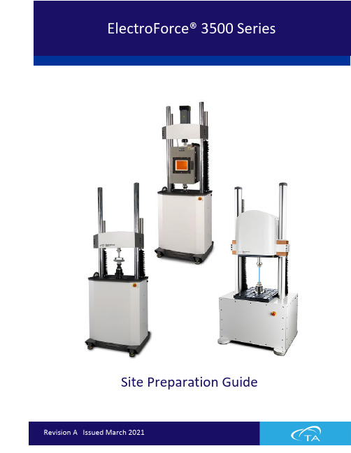
Site Preparation GuideTable of Contents (2)Ideal Setup (3)System Components (4)Instrument Measurements....................................................................................................... 5–6 3510 (5)3520 (5)3550 (6)Power Supply (6)Lifting the Instrument (7)Utility Requirements ................................................................................................................ 8–9 Power (8)Hot/Cold Chamber (9)Miscellaneous (9)Site Preparation Checklist (10)TA Instrument Offices (11)Circulator Power Cooling Gas LN2Fluid Light Hardware Software Temp Lab CustomerIDEAL PLACEMENT AND BENCH MEASUREMENTSSelect a location with adequate floor and ceiling space and a rigid laboratory bench that is level and is in a vibration-free environment.Table depth: 1.2 m (4 ft) Distance from the wall: 0.15 m (0.5 ft) min.Floor space: 91.44 cm x 91.44 cm (3 ft x 3 ft)Table width: 1.5 m (5 ft)MAIN SYSTEM COMPONENTSE A. Test InstrumentD. Power Supply (Axial) B. Computer TowerE. Emergency Stop C. Computer MonitorF. PCI Electronics BoxDAFBC3510 TEST INSTRUMENT3520 TEST INSTRUMENT3550 TEST INSTRUMENTPOWER SUPPLYDepth: 48.3 cm (19 in) Width: 43.2 cm (17 in) Weight: 36 kg (80 lbs)LIFTING THE INSTRUMENTTo avoid system damage, only specified lift points should be used.Proper technique should be used for lifting any system component.A powered lift (fork-lift) should be used when moving the load frame. Avoid pinch points when moving the load frame or other components. Pinchpoints can exist between the load frame and mounting surface or walls during movement of frame.POWERInternational: Line power cord provided is basedon countryUse power cords with plugs appropriate for your circuit.Supply voltages lower than indicated may result in a degradation of performance.Ensure that the mains assigned do not also supply power to noise generating equipment nearby, such as motors, welders, transformers, etc.An independent heavy GROUND wire must be provided through the power hookup. Improper grounding may cause severe damage for which the supplier will not accept responsibility. All power strips must be fully grounded and carry the ground through to the sockets into which the computer is plugged.L 15-30 IEC 60309HOT/COLD CHAMBERGas Liquid nitrogenPressure 152–345 kPa (22–50 psig) Connections ½ -inch SAE, 45-degree flare fittingMISCELLANEOUSOperatingtemperature 18°C (64°F) to 30°C (86°F) Relativehumidity 40–65% (non-condensing)ElectroForce 3500 SeriesFor information on our latest products, contact information, and more, see our website at: .To find your local TA Instruments office and contact information, visit/contact/ta-directory/TA Instruments – Waters LLCCorporate Headquarters159 Lukens DriveNew Castle, DE 19720USATelephone: 302-427-4000Fax: 302-427-4001Email:**********************。
- 1、下载文档前请自行甄别文档内容的完整性,平台不提供额外的编辑、内容补充、找答案等附加服务。
- 2、"仅部分预览"的文档,不可在线预览部分如存在完整性等问题,可反馈申请退款(可完整预览的文档不适用该条件!)。
- 3、如文档侵犯您的权益,请联系客服反馈,我们会尽快为您处理(人工客服工作时间:9:00-18:30)。
本特利内华达资产状态监测
3500 监测系统框架
部件号 129766-01 修订版 L (03/08)
3500 监测系统框架安装与维护手册
版权所有 1995 本特利内华达有限责任公司 保留所为通用电气公司在美国及其他国家的商标:
Bently Nevada, System 1, Keyphasor 以下是引用其他法人实体的商标:
3500 监测系统计算机硬件与软件手册 (128158-01)
• 框架与 3500 上位机连接操作指导 • 通讯校验步骤 • 软件安装步骤 • 数据采集/DDE Server 和操作员显示软件使用指南 • 网络设置与远程通讯步骤及示意图
3500 现场接线图集 (130432-01)
• 特定传感器接线示意图 • 推荐的接线清单
2. 概述 ...................................................................................................................3
2.1 3500 监测系统 ................................................................................................................................... 3 2.1.1 增强的操作信息 ...................................................................................................................... 3 2.1.2 提高了与厂级控制计算机的集成能力 ......................................................................... 4 2.1.3 减少安装与维护成本 ............................................................................................................ 4 2.1.4 改善可靠性 ................................................................................................................................ 4 2.1.5 本安选项 ..................................................................................................................................... 5 2.1.6 多个输出接口 ........................................................................................................................... 5
iii
3500 监测系统框架安装与维护手册
目录
1. 货物接收与处理操作指导..............................................................................1
1.1 货物接收检查 ..................................................................................................................................... 1 1.2 处理与储存注意事项 ...................................................................................................................... 1
2.2 共同特点 ............................................................................................................................................... 5 2.2.1 模块热插拔 ................................................................................................................................ 5 2.2.2 外部端子与内部端子 ............................................................................................................ 5
Velostat 是 3M 公司的商标 Windows 是微软公司的商标 Modbus 是 Modbus-IDA 的商标
联络信息
当您无法与本特利内华达当地代表联系时,请通过下列途径:
邮寄地址
电话 传真 英特网
1631 Bently Parkway South Minden, Nevada USA 89423 USA 1.775.782.3611 1.800.227.5514 1.775.215.2873
/bently
ii
补充信息
注意:
本手册未包含运行与维护该产品所必需的所有信息。如需要请参见下列相关手册。
3500 监测系统框架组态与工具指南 (129777-01)
• 使用 3500 框架组态软件设置模块工作参数的操作指南 • 使用 3500 测试工具软件校验模块输入和输出端子工作是否正常的操作指南
框架内安装的所有模块的操作与维护手册
产品处置声明 使用本产品或产品达到使用寿命期限后的客户和第三方是恰当处置产品废弃物的唯一 责任人。任何个人、公司、组织或者机构在产品使用过程中不得违反美国州法律、美 国联邦法律、或者其他相关国际法律对废弃物的规定。本特利内华达公司不承担产品 使用过程中或者达到寿命期限后废弃物处理的责任。
2.5 本质安全性 - 3500 内部安全栅系统 .....................................................................................15 2.5.1 3500 内部安全栅系统的限制 ..............................................................................................16 2.5.2 3500 内部安全栅系统的特点 ..............................................................................................16
2.4 标准框架继电器选项 ...................................................................................................................... 9 2.4.1 单独继电器 ................................................................................................................................ 9 2.4.2 总线式继电器 .........................................................................................................................11 2.4.3 三重冗余(TMR)系统 ......................................................................................................12
2.3 3500 系统部件 ................................................................................................................................... 6 2.3.1 环境防护箱 ................................................................................................................................ 7 2.3.2 框架 ............................................................................................................................................... 7 2.3.3 电源 ............................................................................................................................................... 8 2.3.4 框架接口模块 ........................................................................................................................... 8 2.3.5 通讯网关模块 ........................................................................................................................... 8 2.3.6 监测器模块 ................................................................................................................................ 8 2.3.7 继电器模块 ................................................................................................................................ 8 2.3.8 键相模块 ..................................................................................................................................... 8 2.3.9 显示模块 ..................................................................................................................................... 9 2.3.10 接地模块 ..................................................................................................................................... 9