AVK阀门
减压阀的阀门类型代号

减压阀的阀门类型代号
减压阀是一种重要的工业设备,用于控制管道、容器或系统中的流体压力,保护设备免受过高压力的损害。
不同类型的减压阀具有不同的阀门类型代号,以下是几种常见的减压阀阀门类型代号。
1. 直角阀(Angle Valve)- 直角阀的阀门类型代号通常为AV。
这种类型的阀门在工业设备中被广泛使用,主要用于调节和控制流体的流量和压力。
2. 双座阀(Double Seat Valve)- 双座阀的阀门类型代号通常为DSV。
这种阀门具有两个阀座,可以同时控制进出口流体的压力,实现精确的压力控制。
3. 气动隔膜阀(Pneumatic Diaphragm Valve)- 气动隔膜阀的阀门类型代号通常为PDV。
这种阀门采用隔膜结构,通过气动装置控制阀门的开关,广泛应用于化工、制药等行业。
4. 定量泄压阀(Proportional Relief Valve)- 定量泄压阀的阀门类型代号通常为PRV。
这种阀门可以根据设定的压力范围,实现恒定的流体泄压,可用于管道和容器的压力保护。
5. 液控调压阀(Liquid Control Pressure Regulator)- 液控调压阀的阀门类型代号通常为LCPR。
这种阀门通过液体压力来调节流体压力,适用于高精度压力控制的场合,如燃料供应系统。
以上是几种常见的减压阀阀门类型代号。
这些阀门类型根据不同的工业需求和应用场合而设计,通过合适的选择和安装,能够确保设备和系统的安全运行,并有效减轻压力对设备的影响。
密封橡胶圈弹性测试说明
AVK 密封橡胶圈弹性测试
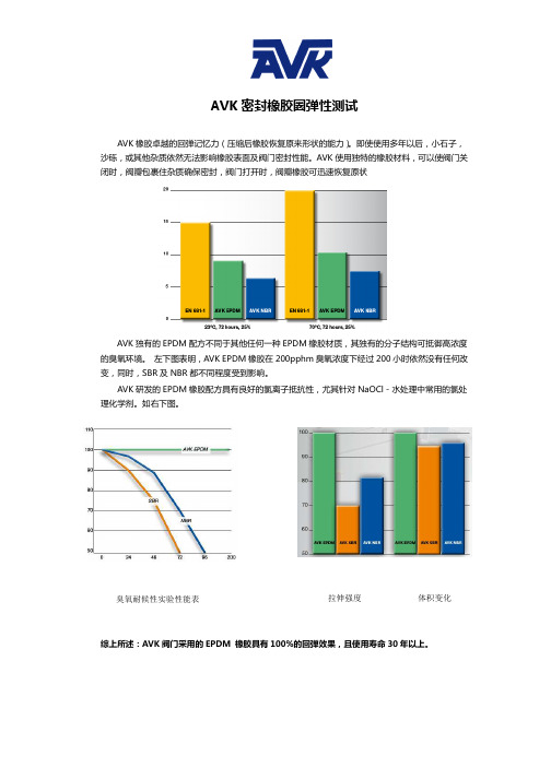
AVK 橡胶卓越的回弹记忆力(压缩后橡胶恢复原来形状的能力)。
即使使用多年以后,小石子,沙砾,或其他杂质依然无法影响橡胶表面及阀门密封性能。
AVK 使用独特的橡胶材料,可以使阀门关闭时,阀瓣包裹住杂质确保密封,阀门打开时,阀瓣橡胶可迅速恢复原状
AVK 独有的EPDM 配方不同于其他任何一种EPDM 橡胶材质,其独有的分子结构可抵御高浓度的臭氧环境。
左下图表明,AVK EPDM 橡胶在200pphm 臭氧浓度下经过200小时依然没有任何改变,同时,SBR 及NBR 都不同程度受到影响。
AVK 研发的EPDM 橡胶配方具有良好的氯离子抵抗性,尤其针对NaOCl-水处理中常用的氯处理化学剂。
如右下图。
综上所述:AVK 阀门采用的EPDM 橡胶具有100%的回弹效果,且使用寿命30年以上。
拉伸强度 体积变化臭氧耐候性实验性能表。
ADVK烟气电动三通蝶阀安装说明书22102C2911
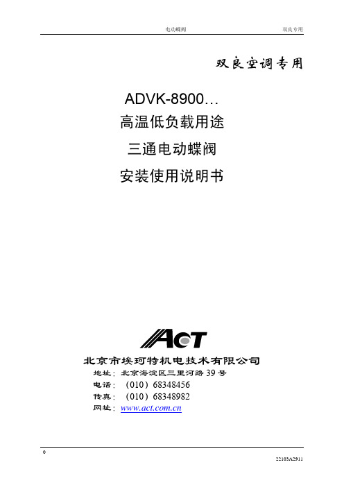
烟气、高炉废气等高温气体介质
主要零部件材质
使用温度 阀体 阀板 阀杆 阀座 轴承 密封填料
≦425℃ Q235A 0Cr18Ni9(304) 2Cr13 0Cr18Ni9(304) 高温滚珠轴承 柔性石墨
≦500℃ 15CrMo 0Cr18Ni9(304) 15CrMo 0Cr18Ni9(304) 高温滚珠轴承 柔性石墨
1. 电动执行机构结构 .......................................................................................... 9 2. 手动操作......................................................................................................... 9 3. 行程凸轮的调整 ............................................................................................ 10 4. 手动限位的调整 ............................................................................................ 10 5. 电位器的调整 ............................................................................................... 11 6. 电路板的调整 ............................................................................................... 11
VAG 操作手册-RIKO-活塞阀-中文
操作维护手册VAG RIKO®活塞阀KAT-B 2010 Edition 7 / 12-1 概述 (3)1.1 安全事项 (3)1.2 正确使用 (3)1.3 标识 (3)2 运输和储存 (3)2.1 运输 (3)2.2 储存 (3)3 产品和功能描述 (4)3.1 功能描述 (4)3.2 应用领域 (4)3.3 运行极限 (5)3.4 正确和不正确的运行模式 (5)4.管线安装 (5)4.1 现场要求 (5)4.2 安装地点 (5)4.3 安装位置 (6)4.4 安装说明和配件 (6)5 调试和试运行 (6)5.1 目检 (6)5.2 功能检查和压力测试 (8)6 执行器安装 (8)6.1 概述 (8)6.2 操作力矩 (8)6.3.安装电动驱动机构 (8)7 维护和保养 (9)7.1 安全说明概述 (9)7.2 检查和驱动间隔 (9)7.3 维护和更换部件 (10)7.3.1 设计 (10)7.3.2 更换阀座密封圈(1.2) (10)7.3.3 更换方截面O型圈(1.4) (10)7.3.4 更换密封圈(1.10和1.1) (10)7.3.5 螺栓拧紧扭矩(Nm) (11)8 故障排除 ..................................................................11VAG保留技术变动及使用相近或更高品质材料的权利,无需发表申明。
图片不具约束力。
1.1 安全事项VAG的阀一切损失VAG不承担任何责任。
对于阀门的使用,常用的技术条款包括(如DIN标,DVGW标-德国燃气和水工业协会,VDI条款-德国工程师协会,VDMA条款-德国机械设备制造业联合会等)。
阀门必须由有资质和特殊培训过的人员安装。
更多规格和信息例如尺寸,材料和应用领域,请参见相关文件(KAT 2014-A)。
VAG阀门设计和制造严格按照国际设计和工业标准。
原则上,它们是安全的。
AVK 29 系列消防阀门安装、操作和维护手册说明书

instruction for useThank you for selecting an AVK product. With correct use, it will give long and reliable service. This manual has been prepared to assist you install, operate and maintain the valve to the maximum efficiency. For ease ofreference, it has been divided into sections covering all aspects of use, and it is in the users best interests to read it and ensure that it is fully understood.1. introductionAVK series 29 hydrants are designed to meet local specifications and include:SA Hydrant - Series 29/010WA Hydrant - Series 29/088NT Hydrant - Series 29/288NZ Squat with 2" round thread outlet - Series 29/588NZ Tall with 2" round thread outlet - Series 29/589Hydrant Isolation Valve - Series 29/00AVK series 29 hydrant valves have DN80 bore.The valves are 100% factory tested hydrostatically.it iS important to StatE opEratinG tEmpEraturE, prESSurE, mEdium and opEratinG conditionS WitH EnQuiriES/ordErS, So tHE moSt SuitaBlE valvE Will BE SuppliEd For your SpEciFic purpoSE.materials:castings (body, bonnet, stem cap, stopper & gland flange)Ductile Iron to AS 1831 Grade 500-7coating Fusion bonded epoxy (FBE)Stem, isolation valve studs, nuts & washers Stainless Steelo-rings NBR rubberStopper rubber EPDM rubberBolts Grade 8.8 encapsulated with hot melt gluethrust collar, stopper nut Dezincification resistant brass CZ 132 to BS 2872Screwed outlet Stainless steel with 316 boltsdust cap PE for screwed outletRefer to individual datasheets for specific information 29/0029/01029/08829/28829/5882. installation•When installing the valve, ensure the flange faces are clean.•To ensure adequate sealing it is important to select the correct type of gasket for the medium concerned, a gasket with the correct flange size must be used.•Place valve onto the pipe flange, and insert the bolts.•Tighten bolts loosely.•Tighten bolts in a diagonal sequence to ensure flanges are pulled parallel.• Finally tighten bolts to correct torque levels as recommended in WSA 109.2.1. Bolts2.1.1 Bolt sizeThe following table shows bolt size you should use for which valve dimensions.table B5 flanging3. operationThis series of screw-down Squat fire hydrants are suitable for use with clean water and neutral liquids, to a maximum temperature of 70°C. Minimum liquid temperature must be above freezing. Insulation is essential for external temperatures on 0°C and below to a limit of -10°C. They are rated for a maximum working pressure of 16 bar unless otherwise agreed and deliver a minimum of 2000 litres per minute at 1.7 Bar gauge.They are normally supplied as CLOCKWISE CLOSE (CC) denoted by a WHITE plastic insert on the Stem Cap.A CLOCKWISE TO OPEN (ACC) version is denoted by a RED plastic insert on the Stem Cap.opEninG / cloSinGNormally by standard ‘Tee’ Bar located on Stem Cap.Closing Torque is 65Nm.SWaBBinGit is not possible to use the Squat type for this purpose.Only the Swept type is suitable for the introduction and retrieval of swabs.dn mm Bolts Quantity80 M 16 4 100 M 16 44. maintenanceSaFEty prEcautionS:When changing obturator (stopper) and/or bonnet ‘O’ ring seal Maintenance Procedures must NOT be carried out whilst the hydrant is installed in a live water main under pressure.4.1. procEdurE for replacement of StEm SEalS and polyamid nylon BuSHSaFEty prEcaution:This procedure can NOT be carried out with the hydrant fully closed under pressure.1) Remove plastic insert (11) by prising out using a thin blade.2) Remove stem cap fixing bolt (10).3) Remove stem cap (9).4) Remove socket head screws (19).5) Twist and pull the gland flange (8) upwards to remove from stem (15). Remove the ‘O’ rings (21) and Bush (20) and ‘O’Ring (7).6) Replace new ‘O’ rings (7) & (20) and Bush (20) by reversing operation described in clause (5). If necessary, lubricate all ‘O’rings with an approved grease.7) Refit socket head screws (19) torque to 15Nm.8) Replace stem cap (9), Bolt (10) and Plastic Insert (11).9) Open and close hydrant to check free running of stem.4.2. procEdurE for replacement of StoppEr (oBturator) and BonnEt ‘o’ rinG SEalSaFEty prEcautionS:This procedure must NOT be carried out with the hydrant under pressure.Check to ensure that there is no pressure in the main by opening the hydrant prior to commencing work.Ensure the main will NOT be recharged before all work on the hydrant is completed.1) Ensure hydrant is in the partly open position by turning stem cap (9) in direction indicated for opening, one or two turns tolift stopper off seat.2) Remove hot melt and socket head screws (17).3) The bonnet can now be removed vertically with the stem cap (9) and stopper (12), it can be easily lifted out of the body. Ifthe hydrant is fitted with a loose stopper (12), this will remain on the valve seat when the bonnet is lifted out of the body(1). Remove ‘O’ ring (6).4) Replace ‘O’ ring (6) locating in body (1) and if necessary lubricate with an approved grease.5) Before locating bonnet/stopper (13) into body (1), check the stopper (obturator) (12) is well up the stem (15) by 3 or 4 fullturns and ensure the stopper (obturator) guides are located to prevent the obturator turning on the stem. The stopper (obturator) guides must both be on the same side of the body guide rails.6) Fit bonnet (13) into Body (1) ensuring the ‘O’ ring (6) remains in position. When correctly aligned the plain face on thebonnet (13) should be in line with the outlet.7) Refit socket head screws (17) torque to 60Nm and fill with silicon.4.3. procEdurE for replacement of FlanGEd outlEt and outlEt ‘o’ rinG SEalSaFEty prEcautionS:Ensure hydrant is closed prior to commencing procedure.procEdurE For rEmoval & rE-aSSEmBly:1) Remove dust cap from outlet.2) Remove outlet by removing 4 head head bolts.3) To replace the outlet (3) and ‘O’ ring (2) if necessary using an approved grease then locate it in the groove in body (1).Ensure dust cap (5) retaining ring is located in small groove on body (1) so that a bolt (4) passes through the ring. Place outlet (3) in position, ensuring that ‘O’ ring (2) is still correctly located and tighten hex head bolts to 60Nm.4.4. procedure for replacement of autoFroSt valvESaFEty prEcautionS:Ensure hydrant is closed prior to commencing procedure.procEdurE For rEmoval and rE-aSSEmBly1) Remove the dust cap from outlet.2) Insert the fitting tool to the auto frost valve with a twisting motion. Squeeze the lugs of the autofrost valve together andpush upwards, if necessary using a short (stubby) screwdriver, at the same time as pulling the special tool and autofrost valve up through the hydrant body and outlet.3) Smear a film of an approved grease on the ‘O’ ring of the new autofrost valve.Fit the new autofrost valve to the fitting tool with a twisting motion and guide it into the body. Push down sharply so that the locking lugs protrude through the underside of the body.4) Carefully open the hydrant to check satisfactory sealing under pressure. The autofrost valve will seal above 0.5 Barpressure.Ensure personnel are not directly above outlet during this part of the procedure.Then close hydrant and check that autofrost valve is draining correctly.5) Refit outlet dust cap to outlet.tEStOn completion of Maintenance requirements:1) Check all item are located correctly.2) Check that all screws are secure.3) Remove dust cap (5) from outlet (3).SaFEty notE:When pressurising the main, it is highly recommended that the hydrant is fractionally open to allow venting of air.4) Check integrity of stopper (obturator) by closing the hydrant in the direction of the arrow on the bonnet.5) Check integrity of the seals by SLOWLY opening the hydrant.6) When all tests have proved satisfactory, close the hydrant.7) Ensure dust cap (5) is always refitted to the outlet (3) when hydrant is not in use. This will prevent the ingress of foreignmatter, stones etc.。
Festo VYKA 2型号媒体分离阀门说明书

Media separated solenoid valves VYKA2d I nternet: /catalogue/...Subject to change – 2023/08Media separated solenoid valves VYKAKey featuresSpecial characteristics• Very easy to clean thanks to media separation• Low media consumption thanks to small internal volume• Materials in contact with the media conform to FDA-listed materials • Developed according to ISO 13485• High-quality materials, therefore also suitable for aggressive media• High flow rate with minimal size (width 7 mm and nominal width 1.2 mm)• High repetition accuracy, switching frequency and precision, therefore also suitable for extremely small volumes and dosing tasks• Low power consumption as a result of holding current reduction• Extremely flexible in use thanks to 3/2-way and 2/2-way variants as well as 12 ... 26 V DC actuationFunctionThe media separated solenoid valve VYKA is designed for installation in laborato-ry devices. The valve is used to control gaseous and liquid media within the limits of the technical data. The chemical resistance of the valve materials coming into contact with the media must be checked for each application. The user is respon -sible for validating the application.The valve VYKA is a directly actuated directional control valve with solenoid coil. In a de-energised state, the valve automatically returns to its normal position. Nor -mally closed and normally open variants are available. The solenoid valve VYKA is additionally available in variants with or without vacuum technology.H- -NoteThe valve uses FDA-listed materials but is not a food materials article in the sense of Regulation (EC) 1935/2004. Country-specific regulations in respect of food contact must be taken into account.Configuration5[1] Terminal contact for E-box VAVE or connecting cable NEBV [2] Solenoid valve[3] Screws for mounting on the sub-base (included in the scope of delivery of thevalves)[4] Sub-base VABS [5] Media connectionsMedia separated solenoid valves VYKA Key featuresActuationH--NoteThe solenoid valve VYKA is controlled by a constant current source. A holdingcurrent reduction is essential as otherwise the valve will significantly heat up. Aholding current reduction can be achieved as follows:When using E-box VAVE, holding current reduction is integrated (recommended).When using connecting cable NEBV, a separate means of holding currentreduction must be provided by the customer.The valve control module VAEM together with the connecting cable NEBV(recommended) offers the option of actuation with holding current reduction.3 2023/08 – Subject to change d I nternet: /catalogue/...Media separated solenoid valves VYKAProduct range overview4d I nternet: /catalogue/...Subject to change – 2023/08Media separated solenoid valves VYKA Type codes5 2023/08 – Subject to change d I nternet: /catalogue/...Media separated solenoid valves VYKAPeripherals overview6d I nternet: /catalogue/...Subject to change – 2023/0872023/08 – Subject to change d I nternet: /catalogue/...Media separated solenoid valves VYKADatasheet-K- 7 mm-M-Flow rateWithout vacuum: 0.013 ... 0.021 m 3/h With vacuum: 0.018 ... 0.021 m 3/hMedia separated solenoid valves VYKADatasheet1)Space between two valves: < 7.5 mm8d I nternet: /catalogue/...Subject to change – 2023/0892023/08 – Subject to change d I nternet: /catalogue/...Media separated solenoid valves VYKADatasheetMedia separated solenoid valves VYKADatasheet10d I nternet: /catalogue/...Subject to change – 2023/08112023/08 – Subject to change d I nternet: /catalogue/...Media separated solenoid valves VYKADatasheetMedia separated solenoid valves VYKADatasheet12d I nternet: /catalogue/...Subject to change – 2023/08132023/08 – Subject to change d I nternet: /catalogue/...Media separated solenoid valves VYKAAccessories1)Packaging unitFesto - Your Partner in AutomationConnect with us/socialmedia 1Festo Inc.2Festo Pneumatic 3Festo Corporation 4Regional Service Center 5300 Explorer DriveMississauga, ON L4W 5G4CanadaAv. Ceylán 3,Col. Tequesquináhuac 54020 Tlalnepantla, Estado de México1377 Motor Parkway Suite 310Islandia, NY 117497777 Columbia Road Mason, OH 45040Festo Customer Interaction CenterTel:187****3786Fax:187****3786Email:*****************************Multinational Contact Center 01 800 337 8669***********************Festo Customer Interaction Center180****3786180****3786*****************************S u b j e c t t o c h a n g e。
AVK闸阀操作指南

Ref.nos.DNLmmHmmDmmDtmmDhmmPN10 PN16dsmmPN10 PN1606-040-7001240140241831501101806-050-70012501502411021651251806-065-70012651702711221851451806-080-70012801802971382001601806-100-701121001903341582201801806-125-701121252003761882502101806-150-701121502104482122852402206-200-70012200230562268340295 29522 2206-250-7001225025066432400350 35522 2606-300-7012300270740370455400 41022 26直径为250mm和300mm阀门上端螺孔为公制螺孔(M20为PN10,M24为PN16)Steel pipeD.ex.LmmHmmFMm重量千 克60.325024114888.2802971714114.33003341925168.33504481949219.14005622470273.04506642788323.950074027128球墨铸铁球墨铸铁球墨铸铁标准:碳钢可选:不锈钢标准:丁晴橡胶可选:氟橡胶高强度钢结构材料说明CL主体及法兰构件CLD主体及法兰构件阀帽,底件及填料函阀门阀座阀座密封阀杆垫密片止推环紧固件及阀塞手轮50—380mm手轮400—600mm闸阀位置指示器罩指示器螺母2.阀杆 阀杆由不锈钢材质制造,具有最佳的延展性与抗拉伸性能。
阀杆上的阀板止停装置能指示阀板全开的位置,在操作过程中起到保护阀杆密封、阀板橡胶和阀门内涂层的作用。
阀杆螺纹是冷辊压成型的,保证了不锈钢的组织结构不变,增加了阀杆的强度。
由于辊压螺纹边缘光滑,从而减小了操作扭矩。
文丘里阀简介
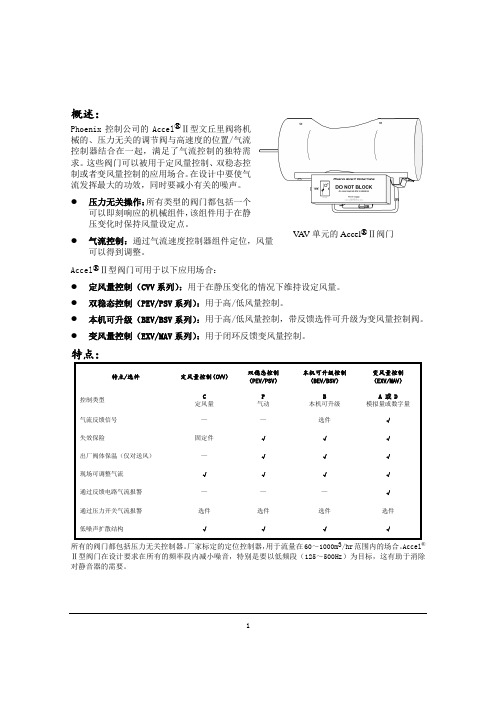
1概述:Phoenix 控制公司的Accel ®Ⅱ型文丘里阀将机械的、压力无关的调节阀与高速度的位置/气流控制器结合在一起,满足了气流控制的独特需求。
这些阀门可以被用于定风量控制、双稳态控制或者变风量控制的应用场合。
在设计中要使气流发挥最大的功效,同时要减小有关的噪声。
●压力无关操作:所有类型的阀门都包括一个可以即刻响应的机械组件,该组件用于在静压变化时保持风量设定点。
●气流控制:通过气流速度控制器组件定位,风量可以得到调整。
Accel ®Ⅱ型阀门可用于以下应用场合: ● 定风量控制(CVV 系列):用于在静压变化的情况下维持设定风量。
● 双稳态控制(PEV/PSV 系列):用于高/低风量控制。
● 本机可升级(BEV/BSV 系列):用于高/低风量控制,带反馈选件可升级为变风量控制阀。
●变风量控制(EXV/MAV 系列):用于闭环反馈变风量控制。
特点:特点/选件定风量控制(CVV )双稳态控制(PEV/PSV )本机可升级控制(BEV/BSV ) 变风量控制(EXV/MAV ) 控制类型 C定风量 P 气动 B本机可升级 A 或 D模拟量或数字量气流反馈信号 — — 选件 √ 失效保险固定件 √ √ √ 出厂阀体保温(仅对送风) — √ √ √ 现场可调整气流 √ √ √ √ 通过反馈电路气流报警 — — — √ 通过压力开关气流报警 选件 选件 选件 选件 低噪声扩散结构√√√√所有的阀门都包括压力无关控制器。
厂家标定的定位控制器,用于流量在60~1000m 3/hr 范围内的场合。
Accel ®Ⅱ型阀门在设计要求在所有的频率段内减小噪音,特别是要以低频段(125~500Hz )为目标,这有助于消除对静音器的需要。
V A V 单元的Accel ®Ⅱ阀门技术特性:结构:♦焊缝连续的16#的离心浇筑铝制阀体。
♦阀体采用不镀膜铝或者带耐腐蚀烘干酚醛涂层。
文丘里阀
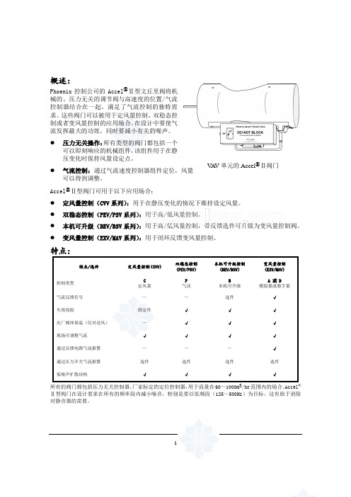
1概述:Phoenix 控制公司的Accel ®Ⅱ型文丘里阀将机械的、压力无关的调节阀与高速度的位置/气流控制器结合在一起,满足了气流控制的独特需求。
这些阀门可以被用于定风量控制、双稳态控制或者变风量控制的应用场合。
在设计中要使气流发挥最大的功效,同时要减小有关的噪声。
● 压力无关操作:所有类型的阀门都包括一个可以即刻响应的机械组件,该组件用于在静压变化时保持风量设定点。
● 气流控制:通过气流速度控制器组件定位,风量可以得到调整。
Accel ®Ⅱ型阀门可用于以下应用场合:● 定风量控制(CVV 系列):用于在静压变化的情况下维持设定风量。
● 双稳态控制(PEV/PSV 系列):用于高/低风量控制。
● 本机可升级(BEV/BSV 系列):用于高/低风量控制,带反馈选件可升级为变风量控制阀。
● 变风量控制(EXV/MAV 系列):用于闭环反馈变风量控制。
特点:特点/选件定风量控制(CVV ) 双稳态控制(PEV/PSV )本机可升级控制(BEV/BSV ) 变风量控制(EXV/MAV ) 控制类型 C定风量 P 气动 B本机可升级 A 或 D 模拟量或数字量气流反馈信号 — — 选件 √ 失效保险固定件 √ √ √ 出厂阀体保温(仅对送风) — √ √ √ 现场可调整气流 √ √ √ √ 通过反馈电路气流报警 — — — √ 通过压力开关气流报警 选件 选件 选件 选件 低噪声扩散结构√√√√所有的阀门都包括压力无关控制器。
厂家标定的定位控制器,用于流量在60~1000m 3/hr 范围内的场合。
Accel ®Ⅱ型阀门在设计要求在所有的频率段内减小噪音,特别是要以低频段(125~500Hz )为目标,这有助于消除对静音器的需要。
V A V 单元的Accel ®Ⅱ阀门技术特性:结构:♦焊缝连续的16#的离心浇筑铝制阀体。
♦阀体采用不镀膜铝或者带耐腐蚀烘干酚醛涂层。
avk工业阀门 - 产品手册说明书
valve solutions for the industryAVK FLOW CONTROLA V K I N D U S T R I A L V A L V E SFLOW CONTROLavK industrial valvesThe resent years’ acquisitions of companies has now formed the basis for a new AVK business area – called AVK Industrial Valves. Here, a wide range of competences have been unified with the purpose to deliver more than just high quality products, but to deliver solutions that help optimise our customers´ businesses.Each of the companies and their respective partners operating within the AVK Industrial Valves business unit has comprehensive expertise within customised valves and accessories, as well as complete solutions.Wouter WitZel orbinoX interaPP World-valve tec artecProduct solutions to oWn sales channelsavK industrial valves coMPaniesFor 40 years, the Dutch company Wouter Witzel has been a leading international manufacturer and supplier of high quality industrial butterfly valves and actuators. The products are used in pipelines as shut-off valves, control valves, and non-return valves. A full range of manual control devices, actuators, and accessories is available for specific conditions.World-Valve is exceptionally adept at grasping and solving specific challenges in specific markets. Within their focus areas of expertise they have invested tremendous amounts of time and effort into charting and understanding all relevant circumstances and requirements. Their knowledge and experience thus gained, translates into quickly delivered quality solutions.Headquartered in Rotkreuz, Switzerland, InterApp operates its own research and development as well as manufacturing, assembly and testing facilities in Switzerland and in Spain. With more than 40 years of experience, InterApp sets technological standards with their proprietory valve and fluid technology.TEC artec with main location in Germany has more than twenty years of experience in engineering special valve products for high pressure and high temperature applications, industrial auxiliary equipment for power plants, gas and oil industry and the petro chemical industry.Wouter WitZel World valveinteraPPtec artecAVK INDUSTRIAL VALVESbrand: industrial valve coMPaniesORBINOX is one of the world’s leading producers of knife gate valves and is present in more than 70 countries worldwide with over 50 years of experience designing, manufacturing, and marketing knife gate valves, penstocks, dampers, and valves for hydraulic works.orbinoX010203eXPect aPPlication KnoWledGe and understandinGeXPectcoMPetent local suPPorteXPect internationalcoordinationsuPPorted by the leadinG coMPanies and Manufacturersof industrial valves, you can eXPect hiGh consistentQuality and serviceavK floW controlAVK FLOW CONTROL delivers optimal valve solutions based on application knowledge and understanding, competentlocal support and international coordination.At AVK FLOW CONTROL, we focus on four main target segments. In this way we are able to heighten the quality of oursolutions, and be closer to our customers at all times.OPTIMAL valve solutionsFOR POWER GENERATIONOPTIMAL valve solutionsFOR THE MINING INDUSTRYOPTIMAL valve solutionsFOR OIL AND GASOPTIMAL valve solutionsFOR WATER TREATMENT PoWer Generationoil and GasMininG industryWater treatMentenGineerinG Pneuton tMseGMent sales ofvalve solutionsavK floW controlsales oc’sbrand: industrial valve coMPaniesindustrial valve headQuaters and avK floW controlentities on selected MarKets.AVK FLOW CONTROLindustrial valves headQuarters:avK floW control a/sKaretmagervej 57100 VejleDenmarkTel.: +45 7585 8408Wouter WitZelIndustrieterrein De Pol 12P.O. Box 54NL-7580 AB LosserThe NetherlandsTel: +31 53 536 95 36Fax: +31 53 536 95 00*******************www.wweurovalve.nlWorld valveLeusinkweg 5-aP.O. Box 1467580 AC LosserThe NetherlandsTel: +31 53 538 1295Fax: +31 53 538 7505*******************orbinoXPº Mikeletegi, 5620009Donostia - San SebastianSpainTel: +34 943 69 80 30Fax: +34 943 65 30 66***************tec artecAm Heidering 7aGewerbepark NordD-16515 OranienburgGermanyTel.: +49 3301 20 32 60Fax: +49 3301 20 32 70interaPPGrundstrasse 24CH-6343 RotkreuzSwitzerlandTel: +41 (0) 41 798 22 33Fax: +41 (0) 41 798 22 34****************.netavK floW controlaustralia6 Wirriga StreetRegency Park, SA 5010AustraliaTel: +61 8 8262 8885Fax: +61 8 8262 7071************************.au.auorbinoX uK /avK floW control uKUnits 6-7 Clock ParkShripney RoadBognor Regis-West SussexPO22 9NHEngland, UKTel: +44 1243 810240Fax: +44 1243 87 00 40**************avK floW controlMiddle east119- Grand Hamad StreetMaackeen HoldingFirst Floor - D122Doha – State Of QatarPhone: +974 44 41 51 81avK floW controlsinGaPore11 Changi North Street 1,#03-11, 498823 SingaporeTel: +65 6542 0451denMarKaustraliauK & irelandMiddle eastsinGaPorevictoria & tasMania T: +61 447 461 908neW south Wales & neW Zealand T: +61 475 959 651T: +61 8 9303 2690F: +61 8 9302 2136E:**************************.au Perth Unit 1, 61 Prosperity Avenue Wangara, WA 6065AustraliaT: +61 8 9022 7228F: +61 8 9022 7230E:***************************.au KalGoorlie2/15 William StreetWest Kalgoorlie, WA 6430Australia T: +61 8 8262 8885F: +61 8 8262 7071E:************************.au head office 559A Grand Junction Road Wingfield, SA 5013Australia T: +61 7 3277 7054F: +61 7 3277 0591E:***************************.aubrisbane67 Musgrave RoadCooper Plains, QLD 4108AustraliaavK floW control Pty ltd .au。
AVK排气阀产品介绍

A VK排气阀产品技术介绍奥维科雅阀门(上海)有限公司气压变化导致空气溢出的案例抽真空现象牛奶水现象奥维科雅阀门(上海)有限公司在水中有压降就有空气从水中溢出1、根据《给水排水设计手册》第一册常用资料(第二版)中91页表5-12数据显示:水温在5℃时,水中空气的溶解量为0.0257m3(气体)/m3(水体);水温在30℃时,水中空气的溶解量为0.0161m3(气体)/m3(水体)水温在30℃时水中空气的溶解量为00161m3(气体)/m3(水体);水温在5℃~30℃之间,我们为便于说明,暂且认为水中空气的溶解量平均约为0.0200m3(气体)/m3(水体)。
2、若水的压力是由一个压力下降到另一个压力(白天到夜间),又若水中空气的溶解量又能在一定的时间内全部释放溢出水体,我们可以认为空气在水中的极限释放量为2%,即可粗略地认为100万吨的水体中可以有2万m3的空气溢出水体,停留在平直管网的上部和起拱的高部、顶部部。
3、气体是可以压缩的。
供水管网中液体流和气体流是同时存在的,因气体是可压缩的,所以,管网中的气体流会形成瞬间的脉动的巨大压力,此压力是与其在同管网中流动的液体流压力的4~10倍。
由此压力造成的管网“爆管”,称为“气爆”。
“气爆”是引起爆管最凶的暗藏的流动的杀手。
的流动的杀手为何使用排气阀管道中的气体会造成很多问题:•增加水锤危险•加大沿程摩阻和局部阻力,增加能源消耗及运行成本•造成流量表错误•压力损失甚至造成断流•造成管道水压试验失真•加速腐蚀Î特别对于长距离大、中口径输配水管道的排气问题十分重要,DN600管道对应水泵流量2500m3/h,扬程提高1m,每年耗电要8万度左右。
气爆高压导致爆管案例①东北某市,输水管长91km,几年运行爆管达108次,沈阳建工学院的专家经分析后结论为气爆;②南方某市输水管仅长860m,管径DN1200,运行年爆管达6次之多,②南方某市输水管仅长860m管径DN1200运行一年爆管达6次之多结论为气爆;③西北某市,管长10.2km,管径DN1200,运行两个月爆管3次。
Valtek MK1和MK2控制阀安装、使用、维修说明书
为了避免可能发生的人身伤害或阀件 损坏,必须严格遵守说明书中的“警告” 和“注意”事项。如果改动本产品,换用 非本厂加工的或劣质的部件,或者采用非 本资料说明的程序进行维修,可能严重影 响产品性能,危及人身安全,损坏设备, 中止保修。
Valtek 件号:49011 Flowserve 公司,Valtek 控制产品,电话:美国 801 489 8611
1-1
3、 如发现运输损坏,应立即与运输公司联 系。
4、 有任何问题时,可与用户当地的 Flowserve 公司代理联系。
安装
1、 安装阀门前,应清除管路中的污垢、焊接 碎屑、锈皮或其它杂物。
生产商 E. I 杜帮公司 石墨产品公司 壳牌石油公司 Garlock 股份公司
表Ⅱ:常用润滑剂
温度范围
应用说明
-5℉到 550℉/ -20℃到 285℃
32℉到 1000℉/ 0℃到 540℃ -100℉到 300℉/ -70℃到 150℃
32℉到 500℉/ 0℃到 260℃
氟化通用润滑脂;所用为通用液体和润滑 脂;对苛刻工质场合能有良好的润滑性; 不易燃,化学稳定性强;与塑料或金属件 相容。 石腊油型的石墨;适用高压;耐磨;600 ℉/316℃以上,保持石墨。
警告:使用本设备或任何工艺控制产品 时,必须遵守标准工业安全规程。对于本设 备来说,作为保修要求,尤其必须使用人身 保护和起吊设备。
注:选用合适的紧固件材料是用户 的责任。通常供货商并不知道阀门的使 用条件或环境。Flowserve 公司的阀体螺 栓连接的标准材料是 B7/2H。对于不锈 钢或合金材质的阀体,以及温度高于 800 ℉/425℃的场合,可以选用 B8(不锈钢) 作为紧固件材料。因此,用户除考虑一 般腐蚀外,还应考虑材料的耐应力腐蚀 断裂性能。像任何机械设备一样,需要 进行定期检查和维修。如需有关紧固件 材料的更详细资料,请与用户当地的 Flowserve 公司代理联系。
博力谋三通阀中文选型
H6..W-SP 系列二通法兰连接型座阀,PN16
10
H7..W-S 系列三通法兰连接型座阀,PN16
11
H7..W-D 系列三通法兰连接型座阀,PN16
12
阀门外形尺寸
13
新一代标准型非自复位座阀执行器
NV..A..-TPC 系列标准型非自复位座阀执行器
14
SV..A..-TPC 系列标准型非自复位座阀执行器
DN [mm]
15 20 25 32 40 50
kvs [m3/h]
1.9 4.4 8 10 20 32
PN16, Tmax=150ºC
Ps [kPa]
800 800 600 550 450 300
Pmax [kPa]
800 800 600 550 450 300
Ps Pmax Ps Pmax [kPa] [kPa] [kPa] [kPa]
IP54
CE 遵循 2004/108/EC
IEC/EN 60730-1, IEC.EN 60730-2-14
0°C..+50°C
-40°C..+80°C
95%相对湿度,无结露
V1. 12.2013 • 资料如有改动,恕不另行通知
5
搏力谋新一代座阀
分流阀和合流阀
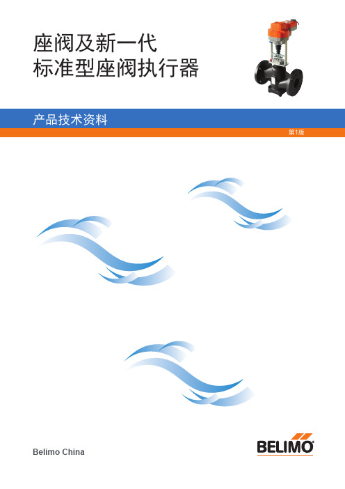
搏力谋座阀是专为介质为冷水、常温水、热水的闭合回路而设计的长使用寿命的控制装置。目前有内螺纹连接和法兰连接型两种。搏力谋座阀 在几个重要的方面进行了大幅的改进。优化的几个特点旨在延长座阀的使用寿命并降低维护成本。阀门总是作为一站式解决方案供货,比如和 匹配的执行器供货。有多种驱动力不同以及带紧急控制功能的执行器型号可选。
33
NV..A..-TPC / SV..A..-TPC安装指南
KVA-3000阀门执行器
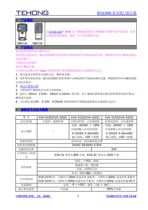
THF3100 THF3200产品特点低交流电压的同步可逆转马达。
动作利用齿轮传送,输出齿轮螺杆组采用绕中心轴旋转的平面滚动轴承支承,阀轴则采用中央螺套连接以及定位圆片。
可附加手动控制杆。
阀动位置指示器。
正比例式0-10V或4-20mm直流控制更可和用跳线选择前向式或逆转式运行。
1、低交流电压的同步可逆转马达,磁性离合器。
2、动作利用齿轮传送,输出齿轮螺杆组采用绕中心轴旋转的平面滚动轴承支撑,阀轴则采用中央螺套连接以及定位标尺。
3、阀动位置指示器。
4、可附加两个辅助性开关及手动控制杆。
5、适用于15mm、17mm、19mm或22mm 的行程。
对于递增反馈型或比例式控制型所用的行程由一跳线进行选择。
6、正比例式0-10V、2-10V、4-20mA直流控制更可用跳线选择前向式或逆转式运行。
驱动器的由一双向同步电机驱动,并带磁性离合器。
电机通过电机转子与离合器所产生的磁性作用,能在停顿的情况下产生稳定的扭力。
所以当电机没有电流通过时能稳定地停顿在任何一点。
驱动器根据递增式或比例式控制器所发的讯号能使电机顺时针转动或逆时针转动。
KVA-3100(KVA-3200)驱动器出厂时选用22mm的行程。
KVA-3102(KVA-3202)驱动器备0~10V 或4~20mA 直流控制信号模式的跳线,用于选择适当的控制模式;KVA-3103(KVA-3203)驱动器备2~10V或4~20mA 直流控制信号模式的跳线,用于选择适当的控制模式。
1、安装前请检查执行器上部是否留有足够的位置,应有100mm的空间,确保安装与拆卸,安装时,应优先口岸旅垂直安装(请参照安装步骤图例)。
2、将驱动器支架套在铜阀连接器上,旋紧驱动器固定螺丝。
3、将阀杆提起,并将刻度指示器套入阀杆,接着转动驱动器连接杆使其旋入阀杆中。
调整好位置后,用扳手将锁紧螺母锁紧。
4、打开执行器罩,连接电源线和信号线(根据电气原理图要求连接),将连接线从进线孔内引入并通电使铜阀关闭,将刻度标尺关闭刻线与刻度指示器对准,并将刻度标尺牢固贴于驱动器支架上。
数据中心阀门品牌

AVK蝶阀安装、操作和维护手册说明书

Instruction for useTo guarantee the benefits of the AVK butterfly valves, proper procedures and compliance with the installationinstruction are essential. The installation has to be carried out according to the state of the art and only byqualified personnel. AVK reserves the right to decline responsibility for damage or premature failure if therecommendations contained in this instruction are not being followed.AVKValvesPtyLtd,559AGrandJunctionRoad,Wingfield,SA5013,Australia-T:+61883680900-E:*******************.au-W:.au Version number 2 pp. 1 of 2InstallationFlange facings must be smooth and clean. Rust, welding scores, rests of paint, dirt, etc. must be removed in order to prevent damage of the valve gasket.Butterfly valves, in wafer style design, are suitable for installation between PN10/16 or ANSI150/AS 2129 D/E flanges.The valve should not be mounted in pipes, where the actual bore diameter is less than the nominal bore dimension of the valve. In that case, spacer rings should be fitted between flanges and valve to prevent damage to the disc on opening.The valve should never be installed between flanges which are not parallel to each other.Make sure that pipes and valves are installed concentric. The disc of a misaligned valve may be damaged. Furthermore, it is absolutely inadmissible to carry out any welding on steel piping while the valve is between the flanges. This could destroy the liner of the valve.The flanges may have to be spread in order to ease the installation of the valve and the disc must be partially open.Fully open the disc. Ensure that the piping is aligned. Tighten diagonally opposite the nuts.Flange inside diameter:The AVK butterfly valve has to be mounted between flanges without gasket. NOTE: It has bidirectional tightness.Function test:Prior starting to use the installation, we recommend to do a function test. Therefore the valve must be opened and closed at least once in order to check that the disc doesn’t touch the flanges and that the valve is tight through the passage and toward outside.If a pressure test of the complete piping system is being carried out, it is very important that the testing pressure is not higher than the nominal pressure of the valve. An overpressure could destroy the valve. In order to ensure a reliable function of the butterfly valves, we recommend to operate these at least once monthly.Cleansing of the piping:When cleansing the piping system it is very important to assure that the cleaning products and devices are harmless for the valve.Removal:Before removing the valve from the pipe consider that dangerous fluids might leak. Corresponding measures of precaution have to be applied.When removing the valve from the pipe please take care not to damage the disc and the liner of the valve.Disposal:Please notice that some residues could remain in the inner of the valve and that they might be dangerous for people or the environment. Therefore, the butterfly valve has to be handled with the corresponding caution. After its use, the butterfly valve has to be disposed of according to the state of the art and under consideration of the environment,AVKValvesPtyLtd,559AGrandJunctionRoad,Wingfield,SA5013,Australia-T:+61883680900-E:*******************.au-W:.au Version number 2 pp. 2 of 2。
avk69系列法兰蝶阀参数
avk69系列法兰蝶阀的常见参数介绍
avk69系列法兰蝶阀的主要参数包括公称通径、公称压力、温度范围和连接方式。
1.公称通径:表示阀门的流通能力,单位为毫米(mm)。
2.公称压力:表示阀门能承受的最大压力,单位为帕斯卡(Pa)或兆帕
(MPa)。
avk69系列法兰蝶阀的压力等级分为PN10、PN16、PN25、PN40等多个等级,适用于各种压力环境的管道系统。
3.温度范围:表示阀门适用的温度范围,一般用最低温度和最高温度表示。
4.连接方式:表示阀门与管道的连接方式,一般有法兰连接、丝扣连接等。
此外,该系列蝶阀的规格范围为DN50-DN1200,可以满足不同管道系统的需求。
其材质为优质碳钢、不锈钢等,具有良好的耐腐蚀性和抗磨损性能。
请注意,以上信息仅供参考,具体参数请以产品说明书或制造商提供的信息为准。
avk法兰止回阀内部结构
avk法兰止回阀内部结构好嘞,咱就来说说这avk法兰止回阀内部结构。
你看啊,这avk法兰止回阀呢,就像一个小小的门卫,专门管着水流或者其他流体的单向通行,可有意思啦。
它的内部结构啊,首先有个阀体,这阀体就像是房子的框架,把整个止回阀的各个部分都给支撑起来,稳稳当当的。
这阀体的材质还挺讲究的呢,得结实耐用,不然在那些水流或者流体的冲击下,一下子就散架了,那可就麻烦大了。
再往里看,就有个阀瓣,这个阀瓣啊,就像是一扇只能单向开的门。
正常情况下,流体按照规定的方向流过来的时候,就像是有礼貌的客人,阀瓣就会很听话地被冲开,让流体顺利通过。
嘿,要是这流体想反着来,那可不行,阀瓣就会紧紧地关上,坚决不让这不懂规矩的流体过去,可倔强了呢。
而且这个阀瓣的形状设计得也很巧妙,一般都是那种弧形或者圆形的,这样就能够很好地贴合阀体内部的形状,密封效果特别好。
在阀瓣的周围呢,还有密封件。
这密封件就像是给阀瓣和阀体之间塞了一圈小毛毯,确保一点缝隙都没有。
你想啊,如果没有这个密封件,流体就会偷偷从那些小缝隙里溜过去,那这个止回阀不就成摆设了嘛。
密封件的材料也是根据不同的使用环境来选择的,有的地方需要耐腐蚀性强的,就会选那种特殊的橡胶或者塑料啥的。
还有啊,这止回阀里面还有个弹簧,弹簧就像是一个小助手。
当流体的力量比较小的时候,弹簧就会发挥作用,帮助阀瓣保持关闭的状态。
就好像是一个小弹簧在后面拉着门,不让它随便被一点点小动静就打开。
但是当流体力量足够大,按照正确方向来的时候,弹簧又不会太倔强,会让阀瓣顺利打开。
在整个avk法兰止回阀内部结构里,每个部分都有自己的作用,少了谁都不行。
就像一个小团队一样,大家各司其职,才能保证这个止回阀好好地工作,把单向流体控制得服服帖帖的。
这小小的止回阀内部结构虽然看起来不那么起眼,但这里面的学问可真是不少呢。
你要是真去仔细研究研究,就会发现这里面的设计真的是很巧妙,充满了人类的智慧。
所以啊,可别小看这avk法兰止回阀内部结构,它在很多地方都发挥着不可替代的作用呢。
大连西奥电子工程 常闭阀门控制箱 说明书
阀门控制箱使用说明产品名称:常闭阀门控制箱型号:JKB-AVK版本:V1.1文档编号:JKB-2357大连西奥电子工程有限公司地址:大连市中山路141-6号E-mail:*****************J KB-AVK型常闭阀门控制箱用于开关常闭型电动阀或电磁阀,与JKB系列可燃气体探测系统配合使用,可在报警时自动关闭阀门。
输入电压: AC 220V +10-15% 50Hz最大输出电流: 5A安装方式:壁挂式使用温度: -40℃~+70℃外形尺寸: 300×250×150mm重量: 4kg阀控箱应使用所带附件安装。
注意:阀控箱的安装、使用和维护人员应仔细阅读本说明书。
阀控箱的安装应严格按照接线端子图连接。
在阀控箱内的下部有十位绿色的接线端子,如下图:L’ N’ G 1 2 C NC L N G接阀门短接或接阀门热保护接控制器或远程联动器常闭点接交流电源“L、N、G”为220V电源输入。
“C、NC”根据相应的联动关系接控制器或远程联动器的一组常闭点。
“1、2”接阀门热保护;若阀门没有热保护应将其短接(出厂状态为短接)。
“L’、N’、G”接阀门电源。
前面板上有一个绿色阀开指示灯。
两个按钮:一个为绿色开阀按钮、一个为红色关阀按钮。
安装接线完毕,通电后,按下开阀按钮则阀门开启,阀开指示灯点亮。
按下关阀按钮则阀门关闭,阀开指示灯熄灭。
电源开关:位于阀控箱内右下角。
功能开关:位于阀控箱内左上角左侧开关向“锁定”侧按下后,前面板上的按钮均失效,可防止未授权者误动。
此开关的出厂设置状态为“解锁”。
当主机需检修、维修或因探测器误报导致控制器向阀控箱发出错误的关阀信号时,可将右侧的船型开关向“维修”侧按下;这样阀控箱将不接收任何来自控制器的信号,可同连接的阀门一起组成一个独立的系统,单独使用。
主机维修后,需将开关向“运行”侧按下。
此开关的出厂设置状态为“运行”。
- 1、下载文档前请自行甄别文档内容的完整性,平台不提供额外的编辑、内容补充、找答案等附加服务。
- 2、"仅部分预览"的文档,不可在线预览部分如存在完整性等问题,可反馈申请退款(可完整预览的文档不适用该条件!)。
- 3、如文档侵犯您的权益,请联系客服反馈,我们会尽快为您处理(人工客服工作时间:9:00-18:30)。
江西 湖北 四川 广东 山西 河南
河南 河北
四川
2 X 30
辽宁 山东
输煤 省份 湖南 业主 华电长沙电厂 国电宝庆电厂 大唐金竹山电厂 中电投贵溪电厂 国电九江电厂 华电黄石电厂 国电鄂州电厂 华电珙县电厂 中电投国际福溪电厂 华电海门电厂 国电肇庆电厂 中电国际神头电厂 国电榆次电厂 华能焦作电厂 华能沁北电厂 华润登封电厂 机组容量(万千瓦) 2 X 30 2 X 60 2 X 60 2 X 60 2 X 60 2 X 20 2 X 60 2 X 30 2 X 60 2 X 100 2 X 30 2 X 60 2 X 30 2 X 60 2 X 100 2 X 60
脱硫 省份 陕西 宁夏 广东 业主 大唐户县二电厂 中宁电厂 潮州电厂 珠江电厂 沙角电厂 瑞明电厂 石门电厂二期 株洲电厂 岳阳电厂 新乡电厂 平顶山电厂 恒丰电厂 沧州电厂 华能上安电厂 江油电厂 泸州电厂 岷山电厂 铁岭电厂 德州电厂 机组容量(万千万) 2 X 60 2 X 33
湖南
2 X 30 2 X 30
AVK阀门电力部分业绩 化学水 业主 泸州电厂 华能淮阴电厂 国华余姚电厂 金华燃机电厂 国华浙江北仑电厂 华能玉环电厂 华能铜川电厂 大唐韩城第二发电厂 张掖电厂一期 华电青海大通电厂 中宁电厂一期 灵武电厂二期 宁夏马莲台电厂一期
省份 四川 江苏 浙江
机组容量(万千瓦)陕西源自甘肃 青海 宁夏2 X 60 2 X 60 2 X 30 2 X 33 2 X 33 2 X 100 2 X 33
