南京06年高考录取率75.21% 65人考上北大清华
高一数学 2.2函数的表示法(备课资料) 大纲人教版必修
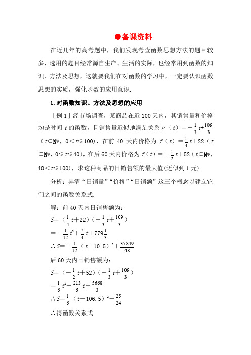
●备课资料在近几年的高考题中,我们发现考查函数思想方法的题目较多,选用的题目经常源自生产、生活的实际,也经常用到函数的知识、方法及思想,这就要我们在对函数的学习中,一定要认识函数思想的实质,强化函数的应用意识.1.对函数知识、方法及思想的应用[例1]经市场调查,某商品在近100天内,其销售量和价格均是时间t 的函数,且销售量近似地满足关系g(t )=-31t +3109(t ∈N *,0<t ≤100),在前40天内价格为f (t )=41t +22(t∈N *,0≤t ≤40),在后60天内价格为f (t )=-21t +52(t ∈N *,40<t ≤100),求这种商品的日销售额的最大值(近似到1元).分析:弄清“日销量”“价格”“日销额”这三个概念以建立它们之间的函数关系式.解:前40天内日销售额为:S =(41t +22)(-31t +3109) =-121t 2+47t +77931 ∴S =-121(t -10.5)2+4837849 后60天内日销售额为:S =(-21t +52)(-31t +3109) =61t 2-6213t +35668 ∴S =61(t -106.5)2-2425 ∴得函数关系式S =⎪⎪⎩⎪⎪⎨⎧N ∈≤<--N ∈≤<+--*)10040(2425)5.106(61*)400(4837849)5.10(12122t t t t t t 且且 由上式可知:对于0<t ≤40且t ∈N *,有当t =10或11时,S max ≈809对于40<t ≤100且t ∈N *,有当t =41时,S max =714.综上所述得:当t =10或11时,S max ≈809答:第10天或11天日售额最大值为809元[例2]某中学高一年级学生李鹏,对某蔬菜基地的收益作了调查,该蔬菜基地种植西红柿,由历年市场行情得知,从2月1日起的300天内,西红柿市场售价与上市时间的关系用图一的一条折线表示;西红柿的种植成本与上市时间的关系用图二的抛物线段表示,试解答下列问题.(注:市场售价和种植成本的单位:元/102kg ,时间单位:天)(1)写出图一表示的市场售价间接函数关系P =f (t ).写出图二表示的种植成本与时间的函数关系式Q =g (t )(2)认定市场售价减去种植成本为纯收益,问何时上市的西红柿纯收益最大?解:(1)由图一可得市场售价间接函数关系为,f (t )=⎩⎨⎧≤≤-≤≤-)300200(,3002)2000(,300t t t t 由图二可得种植成本间接函数关系式为g (t )=2001(t -150)2+100,(0≤t ≤300) (2)设t 时刻的纯收益为h (t ),则由题意得h (t )=f (t )-g(t )即h (t )=⎪⎪⎩⎪⎪⎨⎧≤<-+-≤≤++-)300200(,21025722001)2000(,217521200122t t t t t t 当0≤t ≤200时,得h (t )=-2001(t -50)2+100 ∴当t =50时,h (t )取得在t ∈[0,200]上的最大值100; 当200<t ≤300时,得h (t )=-2001(t -350)2+100 ∴当t =300时,h (t )取得在t ∈(200,300]上的最大值87.5 综上所述由100>87.5可知,h (t )在t ∈[0,300]上可以取得最大值是100,此时t =50,即从2月1日开始的第50天时,上市的西红柿收益最大.评述:(1)以上两例都是考查用数学中函数知识思想、方法去解决实际问题的能力,注意其中关键词的理解,正确找出函数关系式.求最值时配方法是一种常用方法.(2)应用题是高考热点问题,且应用题的具体内容可以多种多样,千变万化,而抽象其数量关系,并建立函数关系式是具有普遍意义的方法.(3)数学应用题因其具有没有固定的背景与题型,难以摸拟分类的特点,也就更接近于我们的生产和实际生活.所以应用题是考查学生创新意识和创新能力的难得的有效题型,同时也不失为提高学生分析问题和解决问题能力的好题型.所以,我们广大师生应加强这一方面的训练,清除心理负面影响,以积极的姿态,迎接数学应用题的挑战,以适应高考的改革要求.二、“应用数学”的能力训练季节性服装当季节即将来临时,价格呈上升趋势,设某服装开始时定价为10元,并且每周(7天)涨价2元,5周后开始保持20元的价格平稳销售;10周后当季节即将过去时,平均每周削价2元,直到16周末,该服装已不再销售.(1)试建立价格P 与周次t 之间的函数关系式.(2)若此服装每件进价Q 与周次t 之间的关系为Q =-0.125(t -8)2+12,t ∈[0,16],t ∈N *.试问该服装第几周每件销售利润L 最大?解:(1)P = ⎪⎩⎪⎨⎧∈∈-∈∈∈∈+*]16,10[ ,240*]10,5[,20*[0,5) , 210N N N t t t t t t t t 且且且 (2)因每件销售利润=售价-进价,即L =P -Q 。
0065选型手册

配有 1/2”ANPT 压簧式接头的传感器,与直接安装的 3144P 或 3144MV 现场安装温度变送器一起使用,或 使用罗斯蒙特接线盒。 这些装配件需要在接线盒内安 装一端子块。
传感器和附件 (公制版)
产品数据表
00813-0206-2654,版本 GA 2006 年 11 月
导言
概述
罗斯蒙特一体化安装的温度传感器、附件硬件及装配 件组成了一套完整的工业温度传感仪表。 多种电阻式 温度检测器和热电偶传感器可单独使用,或作为完整 装配件使用,完整装配件包括接线盒、热电偶套管和 延伸附件。 这里所提供的产品是为全套温度测量装配 件的应用而设计的,包括罗斯蒙特智能型和可编程温 度变送器。 请向当地罗斯蒙特代表咨询详细信息。
N
NiCrSi (+ 玫瑰红), NiSi ( - 白色) Nicrobell B
185 系列热电偶
构造
热电偶由两种不同金属之间的接点构成,该接点产生的热电电动势 变化与温度变化有关。罗斯蒙特 185 系列热电偶传感器由精选材料 制成,符合 IEC 584 1 级容差。导线的接点采用焊接,以形成纯连 接、保持电路完整性并确保达到最高精度。 无接地接点由传感器铠 装保护免受环境影响。 无接地和绝缘接点与传感器铠装实现电气绝 缘。
65 系列铂电阻式温度检测器温度传感器呈现出电阻与 温度存在非常高的线性和稳定关系。 这些传感器主要 用于要求高精度、耐久性和长期稳定性的工业环境。 65 系列传感器的设计符合下列国际标准中的大部分关 键参数:DIN EN 60751 合并修订 1 和 2,DIN 43760 和 BS 1904。(1) 这种标准化使传感器具有可互换性, 而无需调整变送器电路。
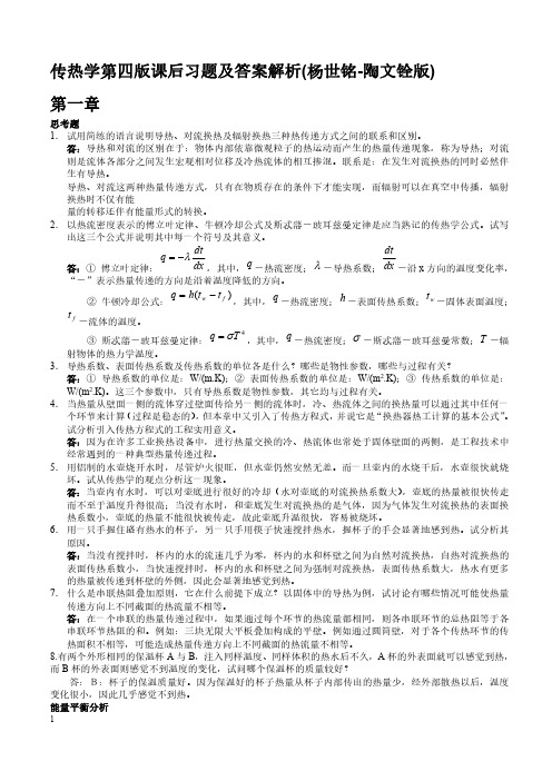
传热学第四版课后习题及答案解析(杨世铭-陶文铨版)
与人处于实际气温、实际风速下的散热量相同。从散热计算的角度可以将人体简化为直径为 25cm、高 175cm、
表面温度为 30℃的圆柱体,试计算当表面传热系数为15W / m2 K 时人体在温度为 20℃的静止空气中的散热 量。如果在一个有风的日子,表面传热系数增加到 50W / m 2 K ,人体的散热量又是多少?此时风冷温度是
片最大允许功率时多少?芯片顶面高出底板的高度为 1mm。
解: max hAt 175W / m2 .K 0.01 0.01 4 0.01 0.001 (85℃-20℃)
=1.5925W
1-15 用均匀的绕在圆管外表面上的电阻带作加热元件,以进行管内流体对流换热的实验,如附图所示。用功
,壁管温度 Tw T f 。试分析热电偶结点的换热方式。
解:具有管道内流体对节点的对流换热,沿偶丝到节点的导热和管道内壁到节点的热辐射。 1-8 热水瓶胆剖面的示意图如附图所示。瓶胆的两层玻璃之间抽成真空,内胆外壁及外胆内壁涂了反射率很
2
低的银。试分析热水瓶具有保温作用的原因。如果不小心破坏了瓶胆上抽气口处的密闭性,这会影响保温效
解:
q
t
,
q t
15 0.04 40 30
0.06W /(m.K )
1-12 在一次测定空气横向流过单根圆管的对流换热实验中,得到下列数据:管壁平均温度 tw=69℃,空气温 度 tf=20℃,管子外径 d=14mm,加热段长 80mm,输入加热段的功率 8.5w,如果全部热量通过对流换热传 给空气,试问此时的对流换热表面传热系数多大?
面传热系数。
解:根据牛顿冷却公式有 Aht
h At 4423.2 W/(m 2 .K)
1-14 一长宽各为 10mm 的等温集成电路芯片安装在一块地板上,温度为 20℃的空气在风扇作用下冷却芯片。
CD74ACT163M96G4,CD74ACT163E,CD74ACT163EE4,CD74ACT163ME4,CD74ACT163MG4, 规格书,Datasheet 资料
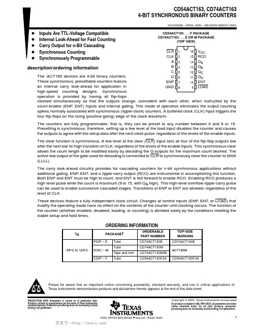
PACKAGING INFORMATIONOrderable Device Status (1)Package Type Package DrawingPins Package Qty Eco Plan (2)Lead/Ball FinishMSL Peak Temp (3)CD54ACT163F3A ACTIVE CDIP J 161TBD A42N /A for Pkg Type CD74ACT163E ACTIVE PDIP N 1625Pb-Free (RoHS)CU NIPDAU N /A for Pkg Type CD74ACT163EE4ACTIVE PDIP N 1625Pb-Free (RoHS)CU NIPDAU N /A for Pkg Type CD74ACT163M ACTIVE SOIC D 1640Green (RoHS &no Sb/Br)CU NIPDAU Level-1-260C-UNLIM CD74ACT163M96ACTIVE SOIC D 162500Green (RoHS &no Sb/Br)CU NIPDAU Level-1-260C-UNLIM CD74ACT163M96E4ACTIVE SOIC D 162500Green (RoHS &no Sb/Br)CU NIPDAU Level-1-260C-UNLIM CD74ACT163M96G4ACTIVE SOIC D 162500Green (RoHS &no Sb/Br)CU NIPDAU Level-1-260C-UNLIM CD74ACT163ME4ACTIVE SOIC D 1640Green (RoHS &no Sb/Br)CU NIPDAU Level-1-260C-UNLIM CD74ACT163MG4ACTIVESOICD1640Green (RoHS &no Sb/Br)CU NIPDAULevel-1-260C-UNLIM(1)The marketing status values are defined as follows:ACTIVE:Product device recommended for new designs.LIFEBUY:TI has announced that the device will be discontinued,and a lifetime-buy period is in effect.NRND:Not recommended for new designs.Device is in production to support existing customers,but TI does not recommend using this part in a new design.PREVIEW:Device has been announced but is not in production.Samples may or may not be available.OBSOLETE:TI has discontinued the production of the device.(2)Eco Plan -The planned eco-friendly classification:Pb-Free (RoHS),Pb-Free (RoHS Exempt),or Green (RoHS &no Sb/Br)-please check /productcontent for the latest availability information and additional product content details.TBD:The Pb-Free/Green conversion plan has not been defined.Pb-Free (RoHS):TI's terms "Lead-Free"or "Pb-Free"mean semiconductor products that are compatible with the current RoHS requirements for all 6substances,including the requirement that lead not exceed 0.1%by weight in homogeneous materials.Where designed to be soldered at high temperatures,TI Pb-Free products are suitable for use in specified lead-free processes.Pb-Free (RoHS Exempt):This component has a RoHS exemptionfor either 1)lead-based flip-chip solder bumps used between the die and package,or 2)lead-based die adhesive used between the die and leadframe.The component is otherwise considered Pb-Free (RoHS compatible)as defined above.Green (RoHS &no Sb/Br):TI defines "Green"to mean Pb-Free (RoHS compatible),and free of Bromine (Br)and Antimony (Sb)based flame retardants (Br or Sb do not exceed 0.1%by weight in homogeneous material)(3)MSL,Peak Temp.--The Moisture Sensitivity Level rating according to the JEDEC industry standard classifications,and peak solder temperature.Important Information and Disclaimer:The information provided on this page represents TI's knowledge and belief as of the date that it is provided.TI bases its knowledge and belief on information provided by third parties,and makes no representation or warranty as to the accuracy of such information.Efforts are underway to better integrate information from third parties.TI has taken and continues to take reasonable steps to provide representative and accurate information but may not have conducted destructive testing or chemical analysis on incoming materials and chemicals.TI and TI suppliers consider certain information to be proprietary,and thus CAS numbers and other limited information may not be available for release.In no event shall TI's liability arising out of such information exceed the total purchase price of the TI part(s)at issue in this document sold by TI to Customer on an annual basis.PACKAGE OPTION ADDENDUM15-Oct-2009Addendum-Page 1TAPE AND REEL INFORMATION*All dimensions are nominalDevicePackage Type Package Drawing Pins SPQReel Diameter (mm)Reel Width W1(mm)A0(mm)B0(mm)K0(mm)P1(mm)W (mm)Pin1Quadrant CD74ACT163M96SOICD162500330.016.46.510.3 2.18.016.0Q1*All dimensions are nominalDevice Package Type Package Drawing Pins SPQ Length(mm)Width(mm)Height(mm) CD74ACT163M96SOIC D162500333.2345.928.6IMPORTANT NOTICETexas Instruments Incorporated and its subsidiaries(TI)reserve the right to make corrections,modifications,enhancements,improvements, and other changes to its products and services at any time and to discontinue any product or service without notice.Customers should obtain the latest relevant information before placing orders and should verify that such information is current and complete.All products are sold subject to TI’s terms and conditions of sale supplied at the time of order acknowledgment.TI warrants performance of its hardware products to the specifications applicable at the time of sale in accordance with TI’s standard warranty.Testing and other quality control techniques are used to the extent TI deems necessary to support this warranty.Except where mandated by government requirements,testing of all parameters of each product is not necessarily performed.TI assumes no liability for applications assistance or customer product design.Customers are responsible for their products and applications using TI components.To minimize the risks associated with customer products and applications,customers should provide adequate design and operating safeguards.TI does not warrant or represent that any license,either express or implied,is granted under any TI patent right,copyright,mask work right, or other TI intellectual property right relating to any combination,machine,or process in which TI products or services are rmation published by TI regarding third-party products or services does not constitute a license from TI to use such products or services or a warranty or endorsement e of such information may require a license from a third party under the patents or other intellectual property of the third party,or a license from TI under the patents or other intellectual property of TI.Reproduction of TI information in TI data books or data sheets is permissible only if reproduction is without alteration and is accompanied by all associated warranties,conditions,limitations,and notices.Reproduction of this information with alteration is an unfair and deceptive business practice.TI is not responsible or liable for such altered rmation of third parties may be subject to additional restrictions.Resale of TI products or services with statements different from or beyond the parameters stated by TI for that product or service voids all express and any implied warranties for the associated TI product or service and is an unfair and deceptive business practice.TI is not responsible or liable for any such statements.TI products are not authorized for use in safety-critical applications(such as life support)where a failure of the TI product would reasonably be expected to cause severe personal injury or death,unless officers of the parties have executed an agreement specifically governing such use.Buyers represent that they have all necessary expertise in the safety and regulatory ramifications of their applications,and acknowledge and agree that they are solely responsible for all legal,regulatory and safety-related requirements concerning their products and any use of TI products in such safety-critical applications,notwithstanding any applications-related information or support that may be provided by TI.Further,Buyers must fully indemnify TI and its representatives against any damages arising out of the use of TI products in such safety-critical applications.TI products are neither designed nor intended for use in military/aerospace applications or environments unless the TI products are specifically designated by TI as military-grade or"enhanced plastic."Only products designated by TI as military-grade meet military specifications.Buyers acknowledge and agree that any such use of TI products which TI has not designated as military-grade is solely at the Buyer's risk,and that they are solely responsible for compliance with all legal and regulatory requirements in connection with such use. TI products are neither designed nor intended for use in automotive applications or environments unless the specific TI products are designated by TI as compliant with ISO/TS16949requirements.Buyers acknowledge and agree that,if they use any non-designated products in automotive applications,TI will not be responsible for any failure to meet such requirements.Following are URLs where you can obtain information on other Texas Instruments products and application solutions:Products ApplicationsAudio /audio Communications and Telecom /communicationsAmplifiers Computers and Peripherals /computersData Converters Consumer Electronics /consumer-appsDLP®Products Energy and Lighting /energyDSP Industrial /industrialClocks and Timers /clocks Medical /medicalInterface Security /securityLogic Space,Avionics and Defense /space-avionics-defense Power Mgmt Transportation and /automotiveAutomotiveMicrocontrollers Video and Imaging /videoRFID Wireless /wireless-appsRF/IF and ZigBee®Solutions /lprfTI E2E Community Home Page Mailing Address:Texas Instruments,Post Office Box655303,Dallas,Texas75265Copyright©2011,Texas Instruments Incorporated。
外球面带座轴承规格表

UCP210-291-13/165020615960252021114387M165/8UC210-29P210UCP210-301-7/8UC210-30 UCP210-311-15/16UC210-31 UCP210-322UC210-32 UCP210UC210 UCP211-3225521917160252023126492M165/8UC211-32P211UCP211-332-1/16UC211-33 UCP211-342-1/8UC211-34 UCP211-352-3/16UC211-35 UCP211UC211 UCP212-362-1/460241 184702520251384102M165/8UC212-36P212UCP212-372-5/16UC212-37 UCP212-382-3/8UC212-38 UCP212-392-7/16UC212-39 UCP212UC212 UCP213-402-1/265265203702925271514107M203/4UC213-40P213UCP213-412-9/16UC213-41 UCP213UC213 UCP214-422-5/87026621072312527157M203/4UC214-42P214UCP214-432-11/16UC214-43 UCP214-442-3/4UC214-44 UCP214UC214 UCP215-452-13/167527521774312528163M203/4UC215-45P215UCP215-462-7/8UC215-46 UCP215-472-15/16UC215-47 UCP215-483UC215-48 UCP215UC215 UCP216-503-1/88029223278312530175M203/4UC216-50P216UCP216UC216 UCP217-523-1/48531024783312532187M203/4UC217-52P217UCP217UC217 UCP218-563-1/29032726288332733200M227/8UC218-56P218UCP218UC218Bearing Shaft Dia d Dimensions(mm)Bolt Used Bearing No.Housing No.HousingUCP317-52UCP3173-1/48511242032011045334022096401M27UC317-52UC317P317UCP318-56UCP3183-1/29011843033011045334523596401M27UC318-56UC318P318UCP319-60UCP3193-3/495125470360120503645250103411-1/8M30UC319-60UC319P319UCP320-64UCP3204100140490380120503650275108421-1/8M30UC320-64UC320P320UCP321105140490380120503650280112441-1/8M30UC321P321UCP32211015052040014055405530011746M33UC322P322UCP32412016057045014055406532012651M33UC324P324UCP32613018060048014055407535513554M33UC326P326UCP32814020062050014055407539014559M33UC328P328 BearingUint No.Shaft Dia dDimensinons(mm)Bolt UsedBearing No.Housing No.HousingWt (kg)h a e b S2S1g w Bi n(mm)(in)(in)(mm)UCPE201-81/212495311511142610M85/16UCW201-8PE203UCPE202-99/16UCW202-9UCPE202-105/8UCW202-10UCPE203-1111/16UCW203-11UCPE20112UCW201UCPE20215UCW202UCPE20317UCW203UCPE204-123/412795381613156531M103/8UC204-12PE204UCPE20420UC204UCPE205-1313/1625140105381613167034M103/8UC205-13PE205UCPE205-147/8UC205-14UCPE205-1515/16UC205-15UCPE205-161UC205-16UCPE205UC205UCPE206-171-1/16301651214821171883M141/2UC206-17PE206UCPE206-181-1/8UC206-187527521774312528163M203/4PE215UCPE215-472-15/16UC215-47UCPE215-483UC215-48UCPE215UC215Bearing Unit NO.Shaft DiadDimensions(mm)Bolt Used BearingNo.HousingNo.HousingWt (kg) (in)(mm)h a e b s1s2W Z Bi n mm inUCCP201C-8UCCP202C-9UCCP202C-10UCCP203C-11UCCP201CUCCP202CUCCP203C1/29/165/811/1612151712795381319666231M103/8UC201-8UC202-9UC202-10UC203-11UC201UC202UC203CP201CP202CP203UCCP204C-12UCCP204C3/42012795381319696231M103/8UC204-12UC204CP204UCCP205C-13UCCP205C-14UCCP205C-15UCCP205C-16UCCP205C13/167/815/16125140105381319767034M103/8UC205-13UC205-14UC205-15UC205-16UC205CP205UCCP206C-17UCCP206C-18UCCP206C-19UCCP206C-20UCCP206C1-1/161-1/81-3/161-1/4301651214817218774M141/2UC206-17UC206-18UC206-19UC206-20UC206CP206UCCP207C-20UCCP207C-21UCCP207C-22UCCP207C-23UCCP207C1-1/41-5/161-3/81-7/16351671274817219780M141/2UC207-20UC207-21UC207-22UC207-23UC207CP207UCCP218C UC218Bearing Unit NO.Shaft Dia d Dimensions(mm)Bolt UsedBearing NO.Housing No.HousingWt (kg) (in)(mm)h a e b s2s1g w Bi n(in)(mm)UCAK201-81/2271218935161213543/8M10UCW201-8AK203UCAK202-105/8UCW202-10 UCAK20112UCW201 UCAK20215UCW202 UCAK20317UCW203UCAK204-12 UCAK2043/42013398411612643/8M10UC204-12UC204AK204UCAK205-13 UCAK205-14 UCAK205-15 UCAK205-16 UCAK20513/167/815/1612514010545161216683/8M10UC205-13UC205-14UC205-15UC205-16UC205AK205UCAK206-17 UCAK206-18 UCAK206-19 UCAK206-20 UCAK2061-1/161-1/81-3/161-1/43016012148191517807/16M12UC206-17UC206-18UC206-19UC206-20UC206AK206UCAK207-20 UCAK207-21 UCAK207-22 UCAK207-23 UCAK2071-1/41-5/161-3/81-7/16354616712748191519927/16M12UC207-20UC207-21UC207-22UC207-23UC207AK207UCAK208-24 UCAK208-25 UCAK2081-1/21-9/1640181140541915191007/16M12UC208-24UC208-25UC208AK208UCAK209-26 UCAK209-27 UCAK209-28 UCAK2091-5/81-11/161-3/445190146541915211067/16M12UC209-26UC209-27UC209-28UC209AK209UCAK210-29 UCAK210-30 UCAK210-31 UCAK210-32 UCAK2101-13/161-7/81-15/16250203159571915221137/16M12UC210-29UC210-30UC210-31UC210-32UC210AK210UCAK211-32 UCAK211-33 UCAK211-34 UCAK211-35 UCAK21122-1/162-1/82-3/1655232181602420251255/8M16UC211-32UC211-33UC211-34UC211-35UC211AK211UCAK212-36 UCAK212-37 UCAK212-38 UCAK212-39 UCAK2122-1/42-5/162-3/82-7/166024119064242029138315/8M16UC212-36UC212-37UC212-38UC212-39UC212AK212UCAK213-40 UCAK213-41 UCAK2132-1/22-9/1665248194702922271413/4M20UC213-40UC213-41UC213AK213UCAK214-42 UCAK214-43 UCAK214-44 UCAK2142-5/82-11/162-3/470294232723222291603/4M20UC214-42UC214-43UC214-44UC214AK214UCAK215-45 UCAK215-46 UCAK215-47 UCAK215-48 UCAK2152-13/162-7/82-15/16375304241743222321653/4M20UC215-45UC215-46UC215-47UC215-48UC215AK215BearingUint No.Shaft Dia dDimensinons(mm)Bolt UsedBearing No.Housing No.HousingWt (kg)h a e b t r g w Bi n(mm)(in)(mm)UCPA201-81/2765238M101586231UC201-8PA204UCPA202-99/16UC202-9UCPA211-352-3/16UC211-35UCPA211UC211UCPA212-362-1/46015011468M162515138M16x2UC212-36PA212UCPA212-372-5/16UC212-37UCPA212-382-3/8UC212-38UCPA212-392-7/16UC212-39UCPA212UC212UCPA213-402-1/26516012470M162515150M16x2UC213-40PA213UCPA213-412-9/16UC213-41UCPA213UC213BearingUint No.Shaft Dia dDimensinons(mm)Bolt UsedBearing No.Housing No.HousingWt (Kg)h a e b t r g w Bi n(mm)(in)(mm)UCPG201-8UCPG202-9UCPG202-10UCPG203-11UCPG201UCPG202UCPG2031/29/165/811/16121517553830M61214572610M6X1UCW201-8UCW202-9UCW202-10UCW203-11UCW201UCW202UCW203PG203UCPG201-81/2704938M815146431UC201-8PG204UCPG202-99/16UC202-9UCPG202-105/8UC202-10UCPG203-1111/16UC203-11UCPG204-123/4UC204-12UCPG20112UC201UCPG20215UC202UCPG20317UC203UCPG20420UC204UCPG205-1313/1625755038M10151570UC205-13PG205UCPG205-147/8UC205-14UCPG205-1515/16UC205-15BearingUint No.Shaft Dia dDimensinons(mm)Bolt UsedBearing No.Housing No.HousingWt(kg)h a e b t r g w Bi n(mm)(in)(mm)UCPW201-81/26532M813136531UC201-8PW204UCPW202-99/16UC202-9 UCPW202-105/8UC202-10 UCPW203-1111/16UC203-11 UCPW204-123/4UC204-12 UCPW20112UC201 UCPW20215UC202 UCPW20317UC203 UCPW20420UC204 UCPW205-1313/16257036M1013137034UC205-13PW205UCPW205-147/8UC205-14 UCPW205-1515/16UC205-15 UCPW205-161UC205-16 UCPW205UC205 UCPW206-171-1/16309838M10161582UC206-17PW206UCPW206-181-1/8UC206-18 UCPW206-191-3/16UC206-19 UCPW206-201-1/4UC206-20 UCPW206UC206 UCPW207-201-1/43510345M10191593UC207-20PW207UCPW207-211-5/16UC207-21 UCPW207-221-3/8UC207-22 UCPW207-231-7/16UC207-23 UCPW207UC207 UCPW208-241-1/24011647M12191599UC208-24PW208UCPW208-251-9/16UC208-25 UCPW208UC208 UCPW209-261-5/84512048M121918107UC209-26PW209UCPW209-271-11/16UC209-27UCTB209-261-5/84554127511/220141081/2-13UC209-26TB209UCTB209-271-11/16UC209-27UCTB209-281-3/4UC209-28UCTB209UC209UCTB210-291-13/1650140515/823141185/8-11UC210-29TB210UCTB210-301-7/8UC210-30UCTB210-311-15/16UC210-31UCTB210-322UC210-32UCTB210UC210 BearingUint No.Shaft Dia dDimensinons(mm)Bolt UsedBearing No.Housing No.HousingWt(kg)h a e b S2S1g w Bi n(mm)(in)(in)(mm)UCPH201-81/270127954019131510131M103/8UC201-8PH204UCPH202-99/16UC202-9UCPH202-105/8UC202-10UCPH203-1111/16UC203-11UCPH204-123/4UC204-12UCPH20112UC201UCPH20215UC202UCPH20317UC203UCPH20420UC204UCPH205-1313/16258014010550191316114M103/8UC205-13PH205UCPH205-147/8UC205-14UCPH205-1515/16UC205-15UCPH205-161UC205-16UCPH205UC205UCPH206-171-1/16309016512150211718130M141/2UC206-17PH206UCPH206-181-1/8UC206-18UCPH206-191-3/16UC206-19UCPH206-201-1/4UC206-20UCPH206UC206UCPH207-201-1/4359516712760211719140M141/2UC207-20PH207UCPH215UC215UCPH216-503-1/880170290232125282330253M203/4UC216-50PH216UCPH216UC216BearingUint No.Shaft Dia dDimensinons(mm)Bolt UsedBearing No.Housing No.HousingWt (kg)a e i g l s t z1z Bi n(mm)(in)(in)(mm)UCF201-8UCF202-9UCF202-10UCF203-11UCF201UCF202UCF2031/29/165/811/1612151776541511312610M103/8UCW201-8UCW202-9UCW202-10UCW203-11UCW201UCW202UCW203F203UCF201-81/28664151212231M103/8UC201-8F204UCF202-99/16UC202-9UCF202-105/8UC202-10UCF203-1111/16UC203-11UCF204-123/4UC204-12UCF20112UC201UCF20215UC202UCF20317UC203UCF20420UC204UCF205-1313/16259570161427122M103/8UC205-13F205UCF205-147/8UC205-14UCF205-1515/16UC205-15UCF205-161UC205-16UCF205UC205UCF206-171-1/16301088318143112249M103/8UC206-17F206UCF206-181-1/8UC206-18UCF206-191-3/16UC206-19UCF206-201-1/4UC206-20UCF206UC206UCF215-483UC215-48UCF215UC215UCF216-503-1/88020816534245823M203/4UC216-50F216UCF216UC216UCF217-523-1/48522017536266323M203/4UC217-52F2179 UCF217UC217UCF218-563-1/29023518740266823M203/4UC218-56F218UCF218UC218BearingUint No.Shaft Dia dDimensinons(mm)Bolt UsedBearingUint No.Housing No.HousingWt (kg)a e i g l s z Bi n(mm)(in)(in)(mm)UCF305-147/8251108016132916393815M141/2UC305-14F305UCF305-1515/16UC305-15UCF305-161UC305-16UCF305UC305UCF306-181-1/8301259518153216444317M141/2UC306-18F306UCF306-191-3/16UC306-19UCF306UC306UCF307-201-1/43513510020163619494819M165/8UC307-20F307UCF307-211-5/16UC307-21UCF307-221-3/8UC307-22UCF307-231-7/16UC307-23UCF307UC307UCF308-241-1/24015011223174019565219M165/8UC308-24F308UCF308-251-9/16UC308-25UCF308UC308UCF309-261-5/84516012525184419605722M165/8UC309-26F309UCF309-271-11/16UC309-27UCF309-281-3/4UC309-28UCF309UC309Bearing Unit NO.Shaft DiadDimensions(mm)Bolt Used BearingNo.Housing No.HousingWt (kg) (in)(mm)a e i s z Bi n mm inUCCF201-8 UCCF202-9 UCCF202-10 UCCF203-11 UCCF204-12 UCCF201 UCCF202 UCCF203 UCCF2041/29/165/811/163/412151720866415124631M103/8UC201-8UC202-9UC202-10UC203-11UC204-12UC201UC202UC203UC204CF201CF202CF203CF204UCCF205-13 13/16 259570161251M103/8UC205-13 CF2051UCCF214-42UCCF214-43UCCF214-44UCCF2142-5/82-11/162-3/470193152311998M165/8UC214-42UC214-43UC214-44UC214CF214UCCF215-45UCCF215-46UCCF215-47UCCF215-48UCCF2152-13/162-7/82-15/163752001593419102M165/8UC215-45UC215-46UC215-47UC215-48UC215CF215UCCF216-50UCCF2163-1/8802081653423107M203/4UC216-50UC216CF216UCCF217-52UCCF2173-1/4852201753623111M203/4UC217-52UC217CF217UCCF218-56UCCF2183-1/290235187402312296M203/4UC218-56UC218CF218 BearingUint No.Shaft Dia dDimensinons(mm)Bolt UsedBearing No.Housing No.HousingWt (kg)a e i g l sb t z1z Bi n(mm)(in)(in)(mm)UCFL201-8UCFL202-9UCFL202-10UCFL203-11UCFL201UCFL202UCFL2031/29/165/811/16 12151799151357312610M103/8UCW201-8UCW202-9UCW202-10UCW203-11UCW201UCW202UCW203FL203UCFL201-81/21139015121260231M103/8UC201-8FL204UCFL202-99/16UC202-9UCFL202-105/8UC202-10UCFL203-1111/16UC203-11UCFL204-123/4UC204-12UCFL20112UC201UCFL20215UC202UCFL212-392-7/16UC212-39UCFL212UC212UCFL213-402-1/265258210302450231554M203/4UC213-40FL213UCFL213-412-9/16UC213-41UCFL213UC213UCFL214-422-5/87026521631245423160M203/4UC214-42FL214UCFL214-432-11/16UC214-43UCFL214-442-3/4UC214-44UCFL214UC214UCFL215-45 2-13/167527522534245623165M203/4UC215-45FL215UCFL215-462-7/8UC215-46UCFL215-472-15/16UC215-47UCFL215-483UC215-48UCFL215UC215UCFL216-503-1/88029023334245825180M227/8UC216-50FL216UCFL216UC216UCFL217-523-1/48530524836266325190M227/8UC217-52FL217UCFL217UC217UCFL218-563-1/2903202654026682520596M227/8UC218-56FL218UCFL218UC218BearingUint No.Shaft Dia dDimensinons(mm)Bolt UsedBearing No.Housing No.Weight (kg)a e i g l sb z Bi n(mm)(in)(in)(mm)UCFL305-147/8251501131613291980393815M165/8UC305-14FL305UCFL305-1515/16UC305-15UCFL305-161UC305-16UCFL305UC305UCFL306-181-1/8301801341815322390444317M203/4UC306-18FL306UCFL306-191-3/16UC306-19UCFL319UC319UCFL320-64UCFL32041004403605940944427012510842M39UC320-64UC320FL320UCFL3211054403605940944427012711244M39UC321FL321UCFL3221104703906042964430013111746M39UC322FL322UCFL32412052043065481104733014012651M42UC324FL324UCFL32613055046065501154736014613554M42UC326FL326UCFL32814060050075601255140016114559M45UC328FL328 Bearing Unit NO.Shaft DiadDimensions(mm)Bolt UsedBearing No.HousingNo.HousingWt (kg) (in)(mm)a e i g l s b z Bi n(in)(mm)UCFT201-8UCFT202-9UCFT202-10UCFT203-11UCFT201UCFT202UCFT2031/29/165/811/16 12151711211256026105/16M8UCW201-8UCW202-9UCW202-10UCW203-11UCW201UCW202UCW203FT203UCFT204-12UCFT2043/420112112560315/16M8UC204-12UC204FT204UCFT205-13UCFT205-14UCFT205-15UCFT205-16UCFT20513/167/815/161251241327703/8M10UC205-13UC205-14UC205-15UC205-16UC205FT205UCFT206-17UCFT206-18UCFT206-19UCFT206-20UCFT2061-1/161-1/81-3/161-1/4301411330833/8M10UC206-17UC206-18UC206-19UC206-20UC206FT206UCFLX07UCX07UCFLX08-24UCFLX08-25UCFLX081-1/21-9/164017914822144016111191/2M14UCX08-24UCX08-25UCX08FLX08UCFLX09-26UCFLX09-27UCFLX09-28UCFLX091-5/81-11/161-3/44518915723144016116191/2M14UCX09-26UCX09-27UCX09-28UCX09FLX09UCFLX10-29UCFLX10-30UCFLX10-31UCFLX10-32UCFLX101-13/161-7/81-15/16250216184262044191335/8M16UCX10-29UCX10-30UCX10-31UCX10-32UCX10FLX10 Bearing Unit NO.Shaft Dia d Dimensions(mm)Bolt UsedBearing No.Housing No.HousingWt (kg) (in)(mm)a e i g l S S1S2b f z Bi n mm inUCFA201-8UCFA202-9UCFA202-10UCFA203-11UCFA204-12UCFA201UCFA202UCFA203UCFA2041/29/165/811/163/41215172098781512101040605031M85/16UC201-8UC202-9UC202-10UC203-11UC204-12UC201UC202UC203UC204FA204UCFA205-13UCFA205-14UCFA205-15UCFA205-16UCFA20513/167/815/1612512598161427121351686534M103/8UC205-13UC205-14UC205-15UC205-16UC205FA205UCFA206-17UCFA206-18UCFA206-191-1/161-1/81-3/16 301441171814311213588072M103/8UC206-17UC206-18UC206-19FA206Bearing Unit NO.Shaft Dia d Dimensions(mm)Bolt UsedBearing No.Housing No.HousingWt (kg) (in)(mm)a e b i g l s z n(in)(mm)HCFLU202-10 HCFLU203-11 HCFLU202 HCFLU2035/811/161517995715113/8M10HC202-10HC203-11HC202HC203FLU203HCFLU204-12 HCFLU2043/42090611915173/8M10HC204-12HC204FLU204HCFLU205-14 HCFLU205-15 HCFLU205-16 HCFLU2057/815/1612512399701915303/8M10HC205-14HC205-15HC205-16HC205FLU205HCFLU206-18 HCFLU206-19 HCFLU206-20 HCFLU2061-1/81-3/161-1/4301428220163/8M10HC206-18HC206-19HC206-20HC206FLU206HCFLU207-20 HCFLU207-21 HCFLU207-22 HCFLU207-23 HCFLU2071-1/41-5/161-3/81-7/163515813094211736141/2M12HC207-20HC207-21HC207-22HC207-23HC207FLU207HCFLU208-24 HCFLU208-25 HCFLU2081-1/21-9/1640172103241739141/2M12HC208-24HC208-25HC208FLU208HCFLU209-26 HCFLU209-27 HCFLU209-28 HCFLU2091-5/81-11/161-3/445180108241840161/2M14HC209-26HC209-27HC209-28HC209FLU209HCFLU210-30 HCFLU210-31 HCFLU210-32 HCFLU2101-7/81-15/16250190157114282045185/8M16HC210-30HC210-31HC210-32HC210FLU210HCFLU211-32 2 55217184128312148185/8M16HC211-32 FLU211HCFLU211-34HCFLU211-35HCFLU2112-1/82-3/16HC211-34HC211-35HC211HCFLU212-36HCFLU212-38HCFLU212-39HCFLU2122-1/42-3/82-7/1660237202138342153185/8M16HC212-36HC212-38HC212-39HC212FLU212HCFLU213-40HCFLU2132-1/26525621015238225621M18HC213-40HC213FLU213 HCFLU214-44HCFLU2142-3/47026421615738235821M18HC214-44HC214FLU214 HCFLU215-47HCFLU215-48HCFLU2152-15/1637527522516441246221M18HC215-47HC215-48HC215FLU215BearingUintNo.Shaft DiadDimensinons(mm)Bolt UsedBearingNo.HousingNo.HousingWt (kg)a e i gb r s z Bi n(mm)(in)(in)(mm)UCCFL201-81/21139015126630124631M103/8UC201-8CFL201CFL202CFL203CFL204UCCFL202-99/16UC202-9UCCFL202-105/8UC202-10UCCFL203-1111/16UC203-11UCCFL204-123/4UC204-12UCCFL20112UC201UCCFL20215UC202UCCFL20317UC203UCCFL20420UC204UCCFL205-1313/16251309916147334165134M141/2UC205-13CFL205UCCFL205-147/8UC205-14UCCFL205-1515/16UC205-15UCCFL205-161UC205-16UCCFL205UC205UCCFL206-171-1/1630148117181484401655M141/2UC206-17CFL206UCCFL206-181-1/8UC206-187527522534241688323102M203/4CFL215UCCFL215-472-15/16UC215-47UCCFL215-483UC215-48UCCFL215UC215UCCFL216-503-1/88029023334241889025107M227/8UC216-50CFL216UCCFL216UC216UCCFL217-523-1/48530524836261989525111M227/8UC217-52CFL217UCCFL217UC217UCCFL218-563-1/29032026540262111032512296M227/8UC218-56CFL218UCCFL218UC218Bearing Unit NO.Shaft Dia d Dimensions(mm)Bolt Used BearingNo.Housing No.HousingWt (kg) (in)(mm)a p e i s j k g f t z1z Bi n mm inUCFC201-8UCFC202-9UCFC202-10UCFC203-11UCFC 204-12UCFC201UCFC202UCFC203UCFC2041/29/165/811/163/4121517201007810125762231M103/8UC201-8UC202-9UC202-10UC203-11UC204-12UC201UC202UC203UC 204FC204UCFC205-13UCFC205-14UCFC205-15UCFC205-16UCFC20513/167/815/161251159010126721702M103/8UC205-13UC205-14UC205-15UC205-16UC205FC205UCFC206-17UCFC206-18UCFC206-19UCFC206-201-1/161-1/81-3/161-1/4301251001012882380241M103/8UC206-17UC206-18UC206-19UC206-20FC2061UCFC215UC215UCFC216-50UCFC2163-1/8802402001823161842170M203/4UC216-50UC216FC216UCFC217-52UCFC2173-1/4852502081823182045180M203/4UC217-52UC217FC217UCFC218-56UCFC2183-1/290265220222318205019096M203/4UC218-56UC218FC2188 Bearing Unit NO.Shaft Dia d Dimensions(mm)Bearing No.Housing No.Weight(kg) (in)(mm)o g p q s b k e a w j l h t z Bi nUCT201-8UCT202-9UCT202-10UCT203-11UCT204-12UCT201UCT202UCT203UCT2041/29/165/811/16121517201610513219511276899432216125131UC201-8UC202-9UC202-10UC203-11UC204-12UC201UC202UC203UC204T204UCT205-13UCT205-14UCT205-15UCT205-16UCT20513/167/815/1612516105132195112768997322462257UC205-13UC205-14UC205-15UC205-16UC205T205UCT206-17UCT206-18UCT206-19UCT206-20UCT2061-1/161-1/81-3/161-1/4301610563722571289102113372870262UC206-17UC206-18UC206-19UC206-20UC206T206UCT207-20 1-1/4 351613643722641289102129373078372UC207-20 T207UCT216UC216UCT217-52UCT2173-1/48538291247348157301731982607354162UC217-52UC217T217UCT218-56UCT2183-1/2904030130804814030190215275805517096UC218-56UC218T218Bearing UnitNO.Shaft DiadDimensions(mm)BearingNo.HousingNo.HousingWt (kg) (in)(mm)o g p q s b k e a w j l h Bi nUCT305-14UCT305-15UCT305-16UCT3057/815/161251612623626651280891223626763815UC305-14UC305-15UC305-16UC305T305UCT306-18UCT306-19UCT3061-1/81-3/163018147041287416901001374128854317UC306-18UC306-19UC306T306UCT307-20UCT307-21UCT307-22UCT307-23UCT3071-1/41-5/161-3/81-7/1635201575453080161001111504532944819UC307-20UC307-21UC307-22UC307-23UC307T307UCT308-24UCT308-25UCT3081-1/21-9/16402217835032891811212416250341005219UC308-24UC308-25UC308T308UCT309-26UCT309-27UCT309-28UCT3091-5/81-11/161-3/4452418905534971812513817855381105722UC309-26UC309-27UC309-28UC309T309UCT310-30UCT310-31UCT3101-7/81-15/165027209861371062014015119161401176122UC310-30UC310-31UC310T310UCT311-32 2 55292110566391152215016320766441276625UC311-32 T311UCT311-34 UCT311-35 UCT3112-1/82-3/16UC311-34UC311-35UC311UCT312-36 UCT312-38 UCT312-39 UCT3122-1/42-3/82-7/1660312311371411232216017822071461357126UC312-36UC312-38UC312-39UC312T3125UCT313-40 UCT3132-1/265322511671431342617019023880501467530UC313-40UC313T3136UCT314-44 UCT3142-3/470362513085461402618020225290521557833UC314-44UC314T314UCT315-48 UCT315375362513285461502619221626290551608232UC315-48UC315T315UCT316-50 UCT3163-1/8804228150985316030204230282102601748634UC316-50UC316T316UCT317-52 UCT3173-1/4854230152985317032214240298102641839640UC317-52UC317T317UCT318-56 UCT3183-1/29046301601065717532228255312110661929640UC318-56UC318T318UCT319-60 UCT3193-3/495463116510657180352402703221107219710341UC319-60UC319T319UCT320-64 UCT3204100483217511559200352602903451207521010842UC320-64UC320T320UCT321105483217511559200352602903451207521011244UC321T321UCT322110523818512565215382853203851308023511746UC322T322UCT324120604221014070230453203554321409026712651UC324T324UCT3261306545220150752405035038546515010028513554UC326T32646 UCT3281407050230160802555038041551515510031514559UC328T328Bearing Unit NO.Shaft Dia d Dimensions(mm)Bearing No.Housing No.Weight (kg) (in)(mm)o g p q s b k e a w j l h Bi nUCST204-12 3/420161051321951899432246031UC204-12 ST204UCST212UC212UCST213-40UCST213-41UCST2136532211117041121271511672247051137UC213-40UC213-41UC213ST213UCST214-42UCST214-43UCST214-44UCST2142-5/82-11/162-3/47032211117041121271511672247046137UC214-42UC214-43UC214-44UC214ST214UCST215-45UCST215-46UCST215-47UCST215-48UCST2152-13/162-7/82-15/1637532211117041121271511672327048140UC215-45UC215-46UC215-47UC215-48UC215ST215 Bearing Unit NO.Shaft Dia d Dimensions(mm)Bearing No.Housing No.HousingWt (kg)(in)(mm)a l Bi nUCC201-8UCC202-9UCC202-10UCC203-11UCC201UCC202UCC2031/29/165/811/16 121517722031UC201-8UC202-9UC202-10UC203-11UC201UC202UC203C203UCC204-12UCC2043/420722031UC204-12UC204C204UCC205-13UCC205-14UCC205-15UCC205-16UCC20513/167/815/16125802234UC205-13UC205-14UC205-15UC205-16UC205C205UCC206-17UCC206-18UCC206-191-1/161-1/81-3/16 308527UC206-17UC206-18UC206-19C206Bearing Unit NO.Shaft DiadDimensions(mm)Bearing No.Housing No.HousingWt (kg) (in)(mm)a l Bi nUCC305-14 UCC305-15 UCC305-16 UCC3057/815/1612590263815UC305-14UC305-15UC305-16UC305C305UCC306-18 UCC306-19 UCC3061-1/81-3/1630100284317UC306-18UC306-19UC306C306UCC307-20 UCC307-21 UCC307-22 UCC307-23 UCC3071-1/41-5/161-3/81-7/1635110324819UC307-20UC307-21UC307-22UC307-23UC307C307UCC308-24 UCC308-25 UCC3081-1/21-9/1640120345219UC308-24UC308-25UC308C308UCC309-26 UCC309-27 UCC309-28 UCC3091-5/81-11/161-3/445130385722UC309-26UC309-27UC309-28UC309C309UCC310-30 UCC310-31 UCC3101-7/81-15/1650140406122UC310-30UC310-31UC310C310UCC311-32 UCC311-34 UCC311-35 UCC31122-1/82-3/1655150446625UC311-32UC311-34UC311-35UC311C311UCC312-36 UCC312-38 UCC312-39 UCC3122-1/42-3/82-7/1660160467126UC312-36UC312-38UC312-39UC312C312UCC313-40UCC3132-1/265170507530UC313-40UC313C313UCC314-44UCC3142-3/470180527833UC314-44UC314C314UCC315-48UCC315375190558232UC315-48UC315C315UCC316-50UCC3163-1/880200608634UC316-50UC315C316UCC317-52UCC3173-1/485215649640UC317-52UC317C317UCC318-56UCC3183-1/290225669640UC318-56UC318C318UCC319-60UCC3193-3/4952407210341UC319-60UC319C319UCC320-64UCC32041002607510842UC320-64UC320C320UCC3211052607511244UC321C321UCC3221103008011746UC322C322UCC3241203209012651UC324C324UCC32613034010013554UC326C32619 UCC32814036010014559UC328C328Bearing Unit NO.Shaft Dia d Dimensions(mm)Bearing No.Housing No.Weight (kg) (in)(mm)a w h j s g Bi n cUCECH201-8UCECH202-9UCECH202-10UCECH203-11UCECH204-12UCECH201UCECH202UCECH2031/29/165/811/163/41215172064966440PF3/419310UC201-8UC202-9UC202-10UC203-11UC204-12UC201UC202UC203ECH204。
symbia intevo6ct参数

symbia intevo6ct参数下载提示:该文档是本店铺精心编制而成的,希望大家下载后,能够帮助大家解决实际问题。
文档下载后可定制修改,请根据实际需要进行调整和使用,谢谢!本店铺为大家提供各种类型的实用资料,如教育随笔、日记赏析、句子摘抄、古诗大全、经典美文、话题作文、工作总结、词语解析、文案摘录、其他资料等等,想了解不同资料格式和写法,敬请关注!Download tips: This document is carefully compiled by this editor. I hope that after you download it, it can help you solve practical problems. The document can be customized and modified after downloading, please adjust and use it according to actual needs, thank you! In addition, this shop provides you with various types of practical materials, such as educational essays, diary appreciation, sentence excerpts, ancient poems, classic articles, topic composition, work summary, word parsing, copy excerpts, other materials and so on, want to know different data formats and writing methods, please pay attention!标题:探索Symbia Intevo 6CT参数:优势与应用导言近年来,医学影像技术取得了巨大的进步,其中计算机断层扫描(CT)技术在临床诊断和研究中扮演着至关重要的角色。
Sikaflex

PRODUCT DATA SHEET Sikaflex®-271 PowerCureVersion 03.01 (04 - 2023), en_AU012001252710001000PRODUCT DATA SHEETSikaflex®-271 PowerCureAccelerated glazing adhesiveTYPICAL PRODUCT DATA (FURTHER VALUES SEE SAFETY DATA SHEET)Chemical base Polyurethane Colour (CQP001-1)BlackCure mechanism Moisture-curing A Density (uncured)1.2 kg/l Non-sag properties (CQP061-1)Very good Application temperature 5 ─ 40 °C Open time (CQP526-1)10 minutes B Early tensile lap-shear strength (CQP046-1)See table 1Shore A hardness (CQP023-1 / ISO 48-4)65Tensile strength (CQP036-1 / ISO 527)7 MPa Elongation at break (CQP036-1 / ISO 527)300 %Tear propagation resistance (CQP045-1 / ISO 34)10 N/mm Tensile lap-shear strength (CQP046-1 / ISO 4587) 5 MPa Service temperature (CQP509-1 / CQP513-1)-40 ─ 90 °C Shelf life9 monthsCQP = Corporate Quality Procedure A Provided by PowerCure B 23 °C / 50 % r.h.DESCRIPTIONSikaflex®-271 PowerCure is an accelerated elastic polyurethane adhesive for glazing and vehicle-glass-replacement applications. Suit-able for bonding materials relevant for direct glazing such as paints, glass, ceramic frits, painted and e-coated surfaces in commercial-vehicle production and repair.Curing of Sikaflex®-271 PowerCure is acceler-ated by Sika’s PowerCure technology which makes it largely independent of atmospheric conditions.PRODUCT BENEFITSAccelerated curing and adhesion build-up ▪Excellent application properties▪Ideal for glass replacement in commercial vehicles▪Low climate dependency of the curing speed with Sika® Booster ▪High mechanical strength ▪Solvent-free▪AREAS OF APPLICATIONSikaflex®-271 PowerCure is designed espe-cially for manual direct-glazing application, and vehicle-glass replacement in commercial vehicles. Thanks to the PowerCure Techno-logy Sikaflex®-271 PowerCure exhibits a fast strength and adhesion build-up.This product is suitable for experienced pro-fessional users only. Tests with actual sub-strates and conditions have to be performed to ensure adhesion and material compatibil-ity.1 / 2CURE MECHANISMSikaflex®-271 PowerCure cures by reaction with moisture provided by the accelerator paste and largely independent from atmo-spheric moisture. For typical strength build up data see table below.Time [h]Tensile lap-shear strength at23 °C [MPa]10.72 3.5Table 1: Strength build-up of Sikaflex®-271 PowerCure CHEMICAL RESISTANCESikaflex®-271 PowerCure is generally resistant to fresh water, seawater, diluted acids and di-luted caustic solutions; temporarily resistant to fuels, mineral oils, vegetable and animal fats and oils; not resistant to organic acids, glycolic alcohol, concentrated mineral acids and caustic solutions or solvents.METHOD OF APPLICATIONSurface preparationSurfaces must be clean, dry and free from grease, oil and dust. Surface treatment de-pends on the specific nature of the substrates and is crucial for a long lasting bond. All pre-treatment steps must be confirmed by pre-liminary tests on original substrates consider-ing specific conditions in the assembly pro-cess.ApplicationSetup the PowerCure Dispenser according to the PowerCure User Manual. If the applica-tion is discontinued for more than 2 minutes, the mixer needs to be replaced.Sikaflex®-271 PowerCure can be processed between 5 °C and 40 °C, but changes in react-ivity as well as application properties need to be considered. The optimum temperature for substrate and adhesive is between 15 °C and 25 °C.The open time is significantly shorter in hotand humid climates. The parts must always bejoined within the open time. As a rule ofthumb, a change of + 10 °C reduces the opentime by half.To ensure a uniform thickness of the bondlineit is recommended to apply the adhesive inthe form of a triangular bead (see figure 1).Figure 1: Recommended bead configurationRemovalUncured Sikaflex®-271 PowerCure can be re-moved from tools and equipment with Sika®Remover-208 or another suitable solvent.Once cured, the material can only be re-moved mechanically. Hands and exposed skinhave to be washed immediately using handwipes such as Sika® Cleaner-350H or a suit-able industrial hand cleaner and water. Donot use solvents on skin.FURTHER INFORMATIONThe information herein is offered for generalguidance only. Advice on specific applicationsis available on request from the Technical De-partment of Sika Industry.Copies of the following publications are avail-able on request:Safety Data Sheets▪General GuidelinesBonding and Sealing with 1-componentSikaflex®▪PowerCure User Manual▪PowerCure Quick Reference Guide▪PACKAGING INFORMATIONPowerCure Pack600 mlBASIS OF PRODUCT DATAAll technical data stated in this document arebased on laboratory tests. Actual measureddata may vary due to circumstances beyondour control.HEALTH AND SAFETY INFORMATIONFor information and advice regarding trans-portation, handling, storage and disposal ofchemical products, users shall refer to the ac-tual Safety Data Sheets containing physical,ecological, toxicological and other safety-re-lated data.DISCLAIMERThe information, and, in particular, the re-commendations relating to the applicationand enduse of Sika products, are given ingood faith based on Sika's current knowledgeand experience of the products when prop-erly stored, handled and applied under nor-mal conditions in accordance with Sika's re-commendations. In practice, the differencesin materials, substrates and actual site condi-tions are such that no warranty in respect ofmerchantability or of fitness for a particularpurpose, nor any liability arising out of anylegal relationship whatsoever, can be inferredeither from this information, or from any writ-ten recommendations, or from any other ad-vice offered. The user of the product musttest the product's suitability for the intendedapplication and purpose. Sika reserves theright to change the properties of its products.The proprietary rights of third parties must beobserved. All orders are accepted subject toour current terms of sale and delivery. Usersmust always refer to the most recent issue ofthe local Product Data Sheet for the productconcerned, copies of which will be suppliedon request.PRODUCT DATA SHEET Sikaflex®-271 PowerCure Version 03.01 (04 - 2023), en_AU 012001252710001000Sika Australia Pty Limited ABN 12 001 342 329 Tel: 1300 22 33 482 / 2。
惠洛克MT多声音喇叭和多声音喇叭-灯具K-75-001说明书
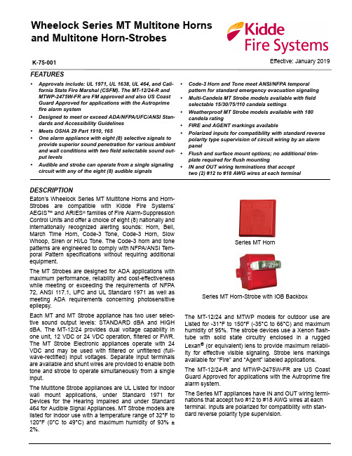
Effective: January 2019K-75-001Wheelock Series MT Multitone Horns and Multitone Horn-StrobesFEATURES•Approvals include: UL 1971, UL 1638, UL 464, and Cali-fornia State Fire Marshal (CSFM). The MT-12/24-R and MTWP-2475W-FR are FM approved and also US Coast Guard Approved for applications with the Autroprime fire alarm system•Designed to meet or exceed ADA/NFPA/UFC/ANSI Stan-dards and Accessibility Guidelines •Meets OSHA 29 Part 1910, 165•One alarm appliance with eight (8) selective signals to provide superior sound penetration for various ambient and wall conditions with two field selectable sound out-put levels•Audible and strobe can operate from a single signaling circuit with any of the eight (8) audible signals•Code-3 Horn and Tone meet ANSI/NFPA temporal pattern for standard emergency evacuation signaling •Multi-Candela MT Strobe models available with field selectable 15/30/75/110 candela settings•Weatherproof MT Strobe models available with 180candela rating•FIRE and AGENT markings available•Polarized inputs for compatibility with standard reverse polarity type supervision of circuit wiring by an alarm panel•Flush and surface mount options; no additional trim-plate required for flush mounting•IN and OUT wiring terminations that accept two (2) #12 to #18 AWG wires at each terminalDESCRIPTIONEaton’s Wheelock Series MT Multitone Horns and Horn-Strobes are compatible with Kidde Fire Systems'AEGIS™ and ARIES ® families of Fire Alarm-Suppression Control Units and offer a choice of eight (8) nationally and internationally recognized alerting sounds: Horn, Bell,March Time Horn, Code-3 Tone, Code-3 Horn, Slow Whoop, Siren or Hi/Lo Tone. The Code-3 horn and tone patterns are engineered to comply with NFPA/ANSI Tem-poral Pattern specifications without requiring additional equipment.The MT Strobes are designed for ADA applications with maximum performance, reliability and cost-effectiveness while meeting or exceeding the requirements of NFPA 72, ANSI 117.1, UFC and UL Standard 1971 as well as meeting ADA requirements concerning photosensitive epilepsy.Each MT and MT Strobe appliance has two user selec-tive sound output levels: STANDARD dBA and HIGH dBA. The MT-12/24 provides dual voltage capability in one unit, 12 VDC or 24 VDC operation, filtered or FWR.The MT Strobe Electronic appliances operate with 24VDC and may be used with filtered or unfiltered (full-wave-rectified) input voltages. Separate input terminals are available and shunt wires are provided to enable both tone and strobe to operate simultaneously from a single input.The Multitone Strobe appliances are UL Listed for indoor wall mount applications, under Standard 1971 for Devices for the Hearing Impaired and under Standard 464 for Audible Signal Appliances. MT Strobe models are listed for indoor use with a temperature range of 32°F to 120°F (0°C to 49°C) and maximum humidity of 93% ±2%.Series MT HornSeries MT Horn-Strobe with IOB BackboxThe MT-12/24 and MTWP models for outdoor use are Listed for -31°F to 150°F (-35°C to 66°C) and maximum humidity of 95%. The strobe devices use a Xenon flash-tube with solid state circuitry enclosed in a rugged Lexan ® (or equivalent) lens to provide maximum reliabil-ity for effective visible signaling. Strobe lens markings available for “Fire” and “Agent” labeled applications.The MT-12/24-R and MTWP-2475W-FR are US Coast Guard Approved for applications with the Autroprime fire alarm system.The Series MT appliances have IN and OUT wiring termi-nations that accept two #12 to #18 AWG wires at each terminal. Inputs are polarized for compatibility with stan-dard reverse polarity type supervision.GENERAL NOTES•Strobes are designed to flash at 1 flash per second minimum over their “Regulated Voltage Range” (16-33v for 24VDC units and 8-17.5v for 12VDC units).•All candela ratings represent minimum effective Multitone Strobe intensity based on UL 1971.•The MT Audible is UL 464 Listed.•“Regulated Voltage Range” is the terminology used by UL to identify the voltage range. Prior to this change, UL used the terminology “Listed Voltage Range.”SPECIFICATIONSTable 3: UL dBA and Current Ratings for Series MT Audible Portion*RMS current ratings are per UL average RMS method. UL max current rating is the maximum RMS current within the listed voltage range (16-33v for 24v units). Forstrobes the UL max current is usually at the minimum listed voltage (16v for 24v units). For audibles the max current is usually at the maximum listed voltage (33v for 24v units). For unfiltered FWR ratings, see installation instructions.ToneRMS Current (Amps)dBA @ 10 FT (UL Reverberant)per UL 46424 VDC12 VDC24 VDC12 VDCHI Output STD Output HI Output STD Output HI OutputSTD OutputHI OutputSTD Output@ 24 VDCUL max *@ 24 VDC UL max *@ 12 VDC UL max *@ 12 VDC UL max *Horn 0.0740.1080.0330.0440.1450.1760.0230.03492879077Bell0.0400.0530.0180.0240.0770.0950.0140.020********March Time Horn 0.0670.1040.0330.0380.1090.1420.0230.03489848974Code-3 Horn 0.0690.0910.0260.0350.1000.1420.0230.03488838873Code-3 Tone 0.0610.0750.0260.0350.0880.1050.0150.021********Slow Whoop 0.0690.0980.0280.0370.1000.1420.0250.0359*******Siren 0.0800.1040.0270.0360.1220.1520.0210.03089848975HI/LO0.0440.0570.0200.0260.0890.1140.0180.02686818671Table 1: Alarm TonesTone Alarm Tones Pattern DescriptionHorn Broadband Horn (Continuous)Bell1560 Hz Modulated (0.07 sec ON/Repeat)March Time Horn Horn (0.25 sec ON/0.25 sec. OFF/Repeat)Code-3 Horn Horn (ANSI S3.41 Temporal Pattern)Code-3 Tone 500 Hz (ANSI S2.41 Temporal Pattern)Slow Whoop500-1200 Hz SWEEP(4.0 sec ON/0.5 sec. OFF/Repeat)Siren 600-1200 HZ SWEEP (1.0 sec. ON/Repeat)Hi/Lo1000/800 (0.25 sec. ON/Alternate)*RMS current ratings are per UL average RMS method. UL max current rating is the maximum RMS current within the listed voltage range (16-33v for 24v units). Forstrobes the UL max current is usually at the minimum listed voltage (16v for 24v units). For audibles the max current is usually at the maximum listed voltage (33v for 24v units). For unfiltered FWR ratings, see installation instructions.Table 2: Current Ratings for Series MT Strobe PortionModelRMS Current (Amps)MTWP-2475MT-24MCW Candela 180cd 15cd 30cd 75cd 110cd 24.0 VDC 0.0940.0410.0630.1090.140UL Max *0.1380.0600.0920.1850.220- 2 -WIRING DIAGRAMSINSTALLATION NOTES1.If the strobe and audible operate on the same cir-cuit, add the strobe current from Table 2 to the audi-ble current from Table 3. For Peak and Inrush current across the listed voltage range, refer to Installation Instructions.2.The average current indicated is per actual Produc-tion Testing at listed VDC. For rated average and Peak current across the UL listed voltage range for both filtered DC and unfiltered VRMS, see Installa-tion Instructions.3.Contact Kidde for Installation Instruction sheets onthese products. These materials contain important information that should be read prior to specifying or installing these products, including:•Total current required by all devices connected to system primary and secondary power sources.•Fuse ratings on signaling circuits to handle maxi-mum inrush or peak currents from all devices onthose circuits.•Composite flash rate from multiple strobes withina person’s field of view.•Installation in office areas and other specification and installation issues.•Use strobes only on circuits with continuously applied operating voltage. Do not use strobes oncoded or interrupted circuits in which the appliedvoltage is cycled on and off, as the strobe maynot flash.•The voltage applied to these products must be within their rated input voltage range.•Conductor size (AWG), length and ampacity should be taken into consideration prior to designand installation of these products, particularly inretrofit installations.4.These notification appliances must be used withintheir published specifications and must be PROP-ERLY specified, applied, installed, operated, main-tained and operationally tested in accordance with their installation instructions at the time of installa-tion and at least twice a year or more often and in accordance with local, state and federal codes, reg-ulations and laws. Specification, application, installa-tion, operation, maintenance and testing must be performed by qualified personnel for proper opera-tion in accordance with all of the latest National Fire Protection Association (NFPA), Underwriters’ Labo-ratories (UL), National Electrical Code (NEC), Occu-pational Safety and Health Administration (OSHA), local, state, county, province, district, federal and other applicable building and fire standards, guide-lines, regulations, laws and codes including, but not limited to, all appendices and amendments and the requirements of the local Authority Having Jurisdic-tion (AHJ). Failure to comply with the installationinstruction sheets could result in improperinstallation, application, and/or operationof these products in an emergency situa-tion, which could result in property damageand serious injury or death.- 3 -This literature is provided for informational purposes only. KIDDE-FENWAL, INC. believes this data to be accurate, but it is published and presented without any guarantee or warranty whatsoever. KIDDE-FENWAL, INC. assumes no responsibility for the product's suitability for a particular application. The fire suppression system design, installation, maintenance, service and troubleshooting must be performed by trained, authorized Kidde Fire Systems distributorsfor the product to work correctly. If you need more information on this product, or if you have a particular problem or question, contact KIDDE-FENWAL, INC., Ashland, MA 01721 USA. Telephone: (508) 881-2000.K-75-001 Rev AD© 2019 Kidde-Fenwal Inc.400 Main Street Ashland, MA 01721 USA Tel: 508.881.2000ARCHITECTS AND ENGINEERS SPECIFICATIONSThe notification appliance shall be an MT Series audible/ visual device or equivalent. Notification appliance shall be electronic and use solid state components. Electrome-chanical alternatives are not approved. Each electronic signal shall provide eight (8) field selectable alarm tones. The tones shall consist of: HORN, BELL, MARCH TIME HORN, CODE-3 HORN, CODE-3 TONE, SLOW WHOOP, SIREN AND HI/LO. Tone selection shall be by durable dip switch assembly and not clips or jumpers. The Multitone Audible appliance shall be UL Listed under Standard 464 for Audible Signal Appliances. The audible and the strobe shall be able to operate from a single noti-fication circuit while producing any of these tones. The device shall provide two output sound levels: STAN-DARD and HIGH dBA. The HIGH dBA setting shall pro-vide a minimum 5 dBA increase in sound output at nominal voltage. The HIGH reverberant dBA measure-ment at 10 feet for the alarm HORN SETTING shall be 88 dBA minimum. Operating voltages shall be 24 VDC using filtered power or unfiltered power supply (full-wave-rectified). All models shall have provisions for standard reverse polarity type supervision and IN/OUT field wiring using terminals that accept #12 to #18 AWG wiring. Combination audible/visual appliances shall incorporate a Xenon flashtube enclosed in a rugged Lexan® lens or equivalent with solid state circuitry. Strobe shall produce a flash rate of one (1) flash per second minimum over the voltage range. The strobe intensity shall be rated per UL and Listed under Standard 1971 for Signaling Devices for the Hearing Impaired with field selectable 15/30/75/110 candela settings. Strobe models shall incorporate cir-cuitry for synchronized strobe flash and shall be designed for compatibility with Kidde Fire Systems’AEGIS and ARIES families of Fire Alarm-Suppression Control Units and DSM Sync Modules. The strobes shall not drift out of synchronization at any time during opera-tion. If the module fails to operate (i.e., contacts remain closed), the strobes shall revert to a non-synchronized default flash rate.All Listed strobe appliances shall incorporate low tem-perature compensation to insure the lowest possible cur-rent consumption. Strobe activation shall be via independent input or from the same input circuit as the audible.The combination audible/visual appliances may be installed indoors and surface or flush mounted. They shall mount to standard electrical hardware requiring no additional trimplate or adapter. The aesthetic appearance shall not have any mounting holes or screw heads visible when the installation is completed. The appliance shall be finished in a textured red color.The audible device may be installed indoors or outdoors with the proper backbox.For weatherproof applications where specifications require 75 cd at -31°F (-35°C) and full temperature range of -31°F to 150°F, the Model MTWP-2475W FR shall be used.ORDERING INFORMATION*Letters correspond to letter of applicable mounting options from datasheet K-75-008. Notes:1.MT-12/24 Audible can be used with the RSSP Multi-Candela for applications requiring 15, 30, 75, 110 cd wall strobes.2.MTWP-2475W is weatherproof and rated for 180 cd@ 77°F (25°C) and 75 cd @ -31°F (-35°C) with low current draw.3.DSM Dual Circuit Modules are rated for 3.0amperes per circuit. Maximum number of intercon-nected DSM modules is twenty (20). Refer to Data Sheet K-75-012 Series DSM Sync Modules. MOUNTING OPTIONSPartNumberInputVoltageRatedCandelaStrobeLabelMounting*OptionsMT-12/24-R12/24------B,H,I,J,K MT-24MCW-FR2415/30/75/110FIRE B,H,I,J,K MT-24MCW-AR2415/30/75/110AGENT B,H,I,J,KMTWP-2475W-FR24180@ 77°F (25°C)75 cd @ -31°F (-35°C)FIREH, H+WP-KIT,SPart Number Mounting Options*DBB-R AISP-R BWBB-R EIOB-R HRP-R JIOB + WP-KIT H, H plus WP-KITWFP SThe MT-12/24-R and the MTWP-2475W-FR can be used in weatherproof applications using mounting options H, H plus the WP-KIT and S.*Letters correspond to letter of applicable mounting options from datasheet K-75-008. For complete mounting options, refer to the Notification Appliance Mounting Accessories datasheet K-75-008.ARIES is a registered trademark of Kidde-Fenwal, Inc. or its parents, subsidiaries or affiliates.EXPORT INFORMATION (USA)Jurisdiction: EARCertification: EAR99 This document contains technical data subject to the EAR.。
Hermary LDM485 有限距离模拟器说明书

U C omplete Isolationwith Optical Couplers and Power DC-to-DC Converter U I ndustrial Surge Protection Devices U S ix LED Diagnostic Indicators U 19.2K Baud at 3 Miles (5KM), 57.6K Baud at 0.5 Miles (0.8KM)U R equest-to-Send,Clear-to-Send Handshake U T ri-State Outputs for Multidrop Applications, up to 64 Devices U S election of Connectors U W ide Operating Temperature Range US olderless Screw Terminal Field ConnectionsFully Isolated Limited Distance Modem, RS232/422 ConverterThe LDM485 is a compact RS232 to RS485 con v erter which fea t ures acomplete electrical iso l a t ionbar r ier and heavy duty elec t ri c alsurge protectors. These devicesfeature a rugged alu m i n umenclosure small enough to mount onthe back panel of typical computerequipment, saving valuable deskand floor space. Isolation ispro v ided by optical couplers anda DC-to-DC converter. The RS232con n ec t ion is through male orfemale EIA 25-pin con n ec t ors. The RS485 connections are madethrough con v en i ent solderless screw terminals.The LDM485 series is designed forfull duplex op e ra t ion over two-wirepairs. Outputs are tri-state, allowing multidropping of up to 64 units.Hardware hand s hake is available over two separate wire pairs. Data rates are DC to 57.6k baud. Six diagnostic LED indicators are provided (see Figure 1) for in s tal l a t ion guid a nce and system trou b leshoot i ng. The RS-232 interface sup p orts Request To Send, Clear T o Send, Data Set Ready, Re c eived Line Signal Detect, and Data Ter m i n al Ready.A convenient null modem switch is pro v ided for the data lines. Also, a line termination switch connects a line termination resistor and line bias re s is t ors to the RS485 receive lines. The RS485 interface supports Request To Send and Clear To Send on separate wire pairs. The LDM485 may be used to convert two sets of send and receive channels by using RTS and CTS circuits as the second data channels. Data rates are thesame. The units use 12 Vac from a wall-mounted transformer to screw terminals 1 and 2 on the RS485 con n ec t or. Al t er n ate l y, they can use ±12 Vdc to pins 9 (+) and 10 (–) of the RS232 connector.The LDM485 conforms to EIA RS232 and RS485 specifications. Data T er m i n al Ready must be asserted by the host RS232 port before the LDM485 can transmit data. When Data Ter m i n al Ready is not as s erted, all outputs of the LDM485 are high impedance, allowing up to 64 LDM485 units to be mul t idrop p ed on a common com mu n i c a t ions cable. See Figures 1 and 3 for details.Request To Send and Clear T o Send are carried through the RS485 port as two separate wire pairs. These may be used for full duplex flow control.Data Terminal Ready, DTR, must be asserted before the LDM485 can trans m it data. This is normally done by the host computer. For situations where the host equipment does not have the capability of supplying a DTR signal, RLSD may be used to automatically assert DTR. On the RS232 connector P1 of each LDM485, simply connect RLSD pin 8 to DTR pin 20. This con n ec t ion is not ap p ro p ri a te for multi-drop installations.for 49-64.LDM485-P shownsmaller than actual sizeLDM485include 120 Vac wall mount transformer.Ordering Example: LDM485-ST converter.Notes: (2) TD = Transmit Data, RD = Receive Data, RTS = Request To Send, CTS = Clear To Send, DTR = Data Terminal Ready, DSR = Data Set Ready, RLSD = Received Line Signal Detect. (3) 120VAC and 220 VAC power transformers are available. (4) Ground-benign environmental conditions (no salt atmosphere, <50°C ambient temperature).OMEGACARE SM available for models shown on this page. Ask your sales representative for full details when placing an order. OMEGACARE SM covers parts, labor and equivalent loaners.。
60N75中文资料
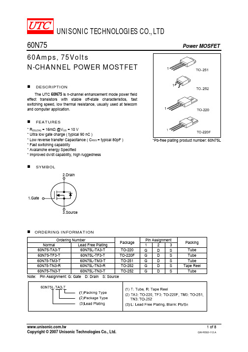
Body Diode Recovery dv/dt VDS (D.U.T.) VDD
Body Diode
Forward Voltage Drop
Fig. 1B Peak Diode Recovery dv/dt Waveforms
UNISONIC TECHNOLOGIES CO., LTD
4 of 8
QW-R502-112.A
元器件交易网
60N75
TEST CIRCUITS AND WAVEFORMS (Cont.)
Power MOSFET
Fig. 2A Switching Test Circuit
Fig. 2B Switching Waveforms
Fig. 3A Gate Charge Test Circuit
Fig. 3B Gate Charge Waveform
L VDS BVDSS IAS RG VDD D.U.T. tp tp Time VDD
ID(t)
VDS(t)
10V
Fig. 4A Unclamped Inductive Switching Test Circuit
THERMAL DATA
SYMBOL θJA θJC MIN TYP MAX 62.5 0.8 UNIT /W /W
PARAMETER Thermal Resistance Junction-Ambient Thermal Resistance Junction-Case
ELECTRICAL CHARACTERISTICS (TC = 25 , unless otherwise specified)
Power MOSFET
TYP
锂电池操作指南说明书
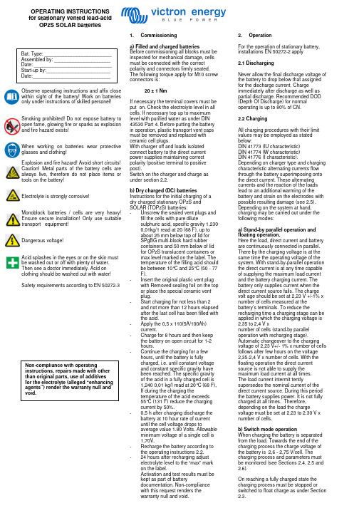
Observe operating instructions and affix close within sight of the battery! Work on batteries only under instructions of skilled personel! Smoking prohibited! Do not expose battery to open fame, glowing fire or sparks as explosion and fire hazard exists! When working on batteries wear protective glasses and clothing! Explosion and fire hazard! Avoid short circuits! Caution! Metal parts of the battery cells are always live, therefore do not place items or tools on the battery!Electrolyte is strongly corrosive! Monoblock batteries / cells are very heavy! Ensure secure installation! Only use suitable transport equipment! Dangerous voltage! Acid splashes in the eyes or on the skin must be washed out or off with plenty of water. Then see a doctor immediately. Acid on clothing should be washed out with water! Safety requirements according to EN 50272-31. Commissioninga) Filled and charged batteriesBefore commissioning all blocks must be inspected for mechanical damage, cells must be connected with the correct polarity and connectors firmly seated. The following torque apply for M10 screw connectors is:20 ± 1 Nm If necessary the terminal covers must be put on. Check the electroiyte level in all cells. If necessary top up to maximum level with purified water as under DIN 43530 Part 4. Before putting the battery in operation, plastic transport vent caps must be removed and replaced with ceramic cell plugs. With charger off and loads isolated connect battery to the direct current power supplies maintaining correct polarity (positive terminal to positive post). Switch on the charger and charge as under section 2.2.b) Dry charged (DC) batteries Instructions for the initial charging of a dry charged stationary OPzS and SOLAR (TOPzS) batteries: - Unscrew the sealed vent plugs and fill the cells with pure dilute sulphuric acid, specific gravity 1,230 0,01kg/1 read at 20 (68 F), up to about 25 mm below top of lid for SPgBG multi-block hard rubber containers and 50 mm below of lid for OPzS translucent containers or max level marked on the label. The temperature of the filling acid should be between 10°C and 25°C (50 - 77 F). - Insert the original plastic vent plug with Removed sealing foil on the top or place the special ceramic ventplug. - Start charging for not less than 2and not more than 12 hours elapsed after the last cell has been filled with the acid. - Apply the 0,5 x 110(5A/100Ah)current. - Charge for 8 hours and then keepthe battery on open circuit for 1-2 hours. - Continue the charging for a fewhours, until the battery is fullycharged, i.e. until constant voltage and constant specific gravity have been reached. The specific gravity of the acid in a fully charged celi is 1,240 0,01 kg/I read at 20°C (68 F), If during the charging thetemperature of the acid exceeds 55°C (131 F) reduce the charging current by 50%. - 0,5 h after charging discharge thebattery at 10 hour rate of current until the cell voltage drops toaverage value 1.80 Volts. Allowable minimum voltage of a single cell is 1,70V.- Recharge the battery according tothe operating instructions 2.2. - 24 hours after recharging adjustelectrolyte level to the “max” mark on the label.Activation and test results must be kept as part of batterydocumentation. Non-compliance with this request renders the warranty null and void.2. OperationFor the operation of stationary battery, installations EN 50272-2 apply2.1 DischargingNever allow the final discharge voltage of the battery to drop below that assigned for the discharge current. Chargeimmediately after discharge as well as partial discharge. Recommended DOD (Depth Of Discharge) for normal operating is up to 80% of CN.2.2 ChargingAll charging procedures with their limit values may be employed as stated below:DIN 41773 (lU characteristic) DIN 41774 (W characteristic) DIN 41776 (I characteristic).Depending on charger type and charging characteristic alternating currents flow through the battery superimposing onto the direct current. These alternating currents and the reaction of the loads lead to an additional warming of the battery and strain on the electrodes with possible resulting damage (see 2.5). Depending on the system at hand, charging may be carried out under the following modes:a) Stand-by parallel operation and floating operation.Here the load, direct current and battery are continuously connected in parallel. There by the charging voltage is at the same time the operating voltage of the system. With stand-by-parallel operation the direct current is at any time capable of supplying the maximum load current and the battery charging current. The battery only supplies current when the direct current source fails. The charge volt age should be set at 2,23 V +/-1% x number of cells measured at the battery’s terminals. To reduce therecharging time a charging stage can be applied in which the charging voltage is 2,35 to 2,4 V xnumber of cells (stand-by parallel operation with recharging stage).Automatic changeover to the charging voltage of 2,23 V+/- 1% x number of cells follows after few hours on the voltage 2,35-2,4 V x number of cells. With the floating operation the direct current source is not able to supply the maximum load current at all times. The load current intermit tentlysupersedes the nominal current of the direct current source. During this period the battery supplies power. It is not fully charged at all times. Therefore, depending on the load the chargevoltage must be set at 2.23 to 2.30 V x number of cells.b) Switch mode operationWhen charging the battery is separated from the load. Towards the end of the charging process the charge voltage of the battery is 2,6 - 2,75 V/cell. The charging process and parameters must be monitored (see Sections 2.4, 2.5 and 2.6).On reaching a fully charged state the charging process must be stopped or switched to float charge as under Section 2.3.OPERATING INSTRUCTIONS for stationary vented lead-acid OPzS SOLAR batteriesc) Battery operation (charge/discharge operation)Only the battery supplies the load. Hereby the charge voltage of the battery towards the end of the charging process is 2,6-2,75 V/cell. The charging process and parameters must be monitored (see Sections 2.4, 2.5 and 2.6). When reaching a fully charged state the charging process must be switched off. The battery can be switched to the load as necessary.2.3 Maintaining the full charge(float charging)Devices complying with the stipulations under DIN 41773 (lU characteristic) must be used. They are to be set so that the average cell voltage is 2,23V +/- 1% (2,25 V +/- 1% for UPS) cell at 20°C and the electrolyte density does not decrease over a protracted period(otherwise see 2.8).2.4 Equalizing chargeEqualizing charges are required after exhaustive discharges and after inadequate charges; they can be carried out as follows:- Up to 72 hours at constant voltage ofmax. 2.4 V/ celI,- With the I or W characteristic as under 2.6. If during equalizingcharging permitted load voltagesare exceeded, appropriatemeasures must be taken, e. g.disconnection of the load. Ifexceeding the maximumtemperature of 55°C the chargingmust either be stopped, proceedwith reduced current, or be switchedto float charge to allow thetemperature to drop. The equalizingcharge is completed when theelectrolyte densities no longerincreases within a period of 2 hours.2.5 Alternating currents with periodic deviationsOn recharging up to 2,4 V/cell as under operation modes a) to c) the actual value of the alternating current is occasionally permitted to reach max. 20 A per 100 Ah nominal capacity. Above 2,4 V/cells 10 A per 100 Ah nominal capacity may not be exceeded. In a fully charged state with a charge voltage of 2,23 to 2,30 V/cell the actual value of the alternating current must not exceed 5 A per 100 Ah nominal capacity.2.6 Charging currentsThe charging currents are not limited up to 2,4 V/ celI. When exceeding the charging voltage of 2,4 V/cell, greater water decomposition occurs. The charging currents per 100 Ah nominal capacity shown in Table 1 must not be exceeded.Charging procedure CellmodelCellvoltageI-charact. 5,0 A 2,6 -2,75W-charact. 7,0 A3,5 A at 2,4 V at 2,65V2.7 TemperatureThe recommended operatingtemperature for Lead-acid batteries is10°C to 30°C. The technical data applyfor the nominal temperature 20°C. Theideal operating temperature is 20 +/- 5°C.Higher temperatures shorten the servicelife. Lower temperatures reduce theavailable capacity. The maximumtemperature of 55°C must not beexceeded.2.8 Temperature-related chargevoltageA temperature-related adjustment of thecharge voltage within the operatingtemperature of 15°C to 25°C is notnecessary. Should the temperaturerange be lower than 15°C and/or higherthan 25°C a temperature relatedadjustment of the charge voltage shouldbe made. The temperature correctionfactor is (-0.004 V/Cell per °K).Should the temperature constantly riseabove 40°C then the factor is (-0.003V/Celi per °K).2.9 ElectrolyteThe electrolyte is diluted sulphuric acid.The nominal electrolyte density is basedon 20°C and the nominal electrolyte levelwhen fully charged with maximumdeviation +/ - 0.01 kg/I. Highertemperatures reduce the electrolytedensity; lower temperatures increase theelectrolyte density. The associatedcorrection factor is 0.0007 kg/I per °K.Example: electrolyte density of 1.23 kg/Iat 35°C corresponds to a density of 1.24kg/I at 20°C or electrolyte density of 1.25kg/I at 5°C corresponds to a density of1.24 kg/I at 20°C.3. Battery maintenance and controlThe electrolyte level must be checkedregularly. If it dropped to the lowestelectrolyte level mark, purified watermust be added as under DIN 43530 Part4, maximum conductivity 30 µS/cm. Toavoid leakage currents keep the batteryclean and dry (especially inter cellconnections). Plastic batterycomponents, in particular the vent caps,must only be cleaned with water thatcontains no additives. At least every 6months the following must bemeasured and recorded:- Battery voltage- Voltage of a few selectedcells/mono block batteries- Electrolyte density of a few selectedcells/mono block batteries- Electrolyte temperature of a fewselected cells/mono block batteries.The following must be measured andrecorded annually:- Voltage of all cells/mono blockbatteries- Electrolyte density of all cells/monoblock batteries- Electrolyte temperature of a fewselected cells/mono block batteries- Should the float charge voltage inone celi deviate more than + 0.1 Vor - 0.05 V from the average value(see 2.3), equalizing chargingshould be done (see 2.4.). Annualvisual checks:- on bolted connectors (check thatunsecured bolt connectors arefirmly seated)- on battery installation orarrangement- on ventilation of battery room.4. TestsTests must be performed on fully chargedbatteries according to EN 60896-1.ln addition, special test instructionssuch as EN 50272-2 must be observed.5. FaultsShould faults be detected in the batteryor the charging device, customerservices should be called in immediately.Measurement records under Section 3are necessary for fast fault detection andremoval.6. Storage and taking out of operationShould cells/batteries be stored or takenout of operation for a longer period oftime, they must be stored fully charged ina dry, frost-free room with max.temperature of 25°C. Direct sunlight orother heat sources mustbe avoided. To avoid damage thefollowing charging methods can bechosen:a. Equalizing charges on a quarterlybasis as under Section 2.4. In average,ambient temperatures of more than 30°Cmonthly equalizing charges may benecessary.b. Float charging as under Section2.3.above.7. TransportBatteries, wet, filled with acid requiretransport under demands of EuropeanAgreement concerning the internationalcarriage of dangerous goods (ADR andRID). ADR special provision No. 598:New batteries are not subject to therequirements of ADR, when:- they are secured in such a way thatthey can not slip, fall or bedamaged;- they are provided with carryingdevices, unless they are suitablystacked, e.g. on pallets;- there are no dangerous traces ofalkalis or acids on the outside;- they are protected against shortcircuits.8. Technical dataThe nominal voltage, the number ofblocks, the nominal capacity (C10 = CN)and the battery type are obtained fromthe type plate.Victron Energy bv / De Paal 35 / 1351 JG ALMERE / The NetherlandsPhone: (+31) (0)36 535 97 00 / Fax: (+31) (0)36 535 97 40 / /e-mail:***********************。
飞机的各种速度
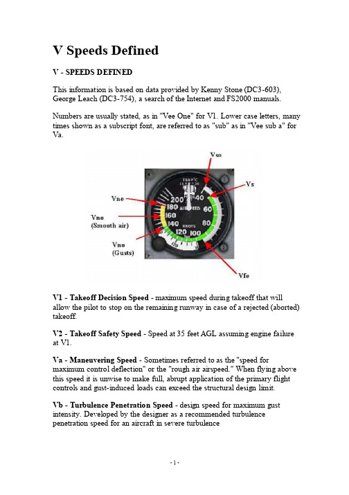
V Speeds DefinedV - SPEEDS DEFINEDThis information is based on data provided by Kenny Stone (DC3-603), George Leach (DC3-754), a search of the Internet and FS2000 manuals. Numbers are usually stated, as in "Vee One" for V1. Lower case letters, many times shown as a subscript font, are referred to as "sub" as in "Vee sub a" for Va.V1 - Takeoff Decision Speed - maximum speed during takeoff that will allow the pilot to stop on the remaining runway in case of a rejected (aborted) takeoff.V2 - Takeoff Safety Speed - Speed at 35 feet AGL assuming engine failure at V1.Va - Maneuvering Speed - Sometimes referred to as the "speed for maximum control deflection" or the "rough air airspeed." When flying above this speed it is unwise to make full, abrupt application of the primary flight controls and gust-induced loads can exceed the structural design limit.Vb - Turbulence Penetration Speed - design speed for maximum gust intensity. Developed by the designer as a recommended turbulence penetration speed for an aircraft in severe turbulenceVbg - Best Power-off Glide Speed - the CAS that provides minimum drag thus a best glide ratio, providing the greatest flight distance available from the potential energy of height.Vbe - Best Endurance Speed - the CAS that gives the greatest airborne time for fuel aboard, i.e., the least fuel consumption per hour.Vbr - Best Range Speed - the speed that provides a lift/drag ratio that provides minimum drag and minimum power required and consequently greatest air distance for fuel on board.Vc - Cruise Speed - the design cruising speed or the optimum cruise speed. Vd - Design Dive Speed - Is usually 1.4 times Vno.Vg - Best Glide Speed - The speed that will afford the best range for a given altitude without engine power.Vh - Maximum Level Flight Indicated Speed (CAS) - the maximum using continuous engine power.Vfe - Maximum Flap Extended Speed - The maximum speed for flight with flaps extended. Indicated by the top end of the White Arc on the Airspeed Indicator. Higher speeds, with flaps down, may result in damage to the flaps or to the extension mechanismVle - Maximum Landing Gear Extended Speed - For planes with retractable landing gear, the maximum speed at which the gear can remain extended without damage to gear doors.Vlo - Maximum Landing Gear Operating Speed - For planes with retractable landing gear, the maximum speed at which the landing gear system can be operated (extend or retract).Vmc - Minimum Control Speed - This is a speed the manufacturer determines based on eight factors specified by the FAA. In general, with gear down and flaps in takeoff position, it is the minimum speed where the pilot can maintain control of the aircraft with the critical engine inoperative.Vmd - Minimum Descent Speed - The speed that results in the lowest rate of sink in a power-off glide, providing the longest duration of flight from the potential energy of height.Vmo - Maximum Operating Speed - The speed that must not be exceeded in any flight regime.Vmu - Minimum Unstick Speed - An indicated speed (CAS) used intake-off conditions where it is advisable to lift off at the lowest possible airspeed to get the tires off the surface, e.g. soft field or wet grass and safely fly in ground effect until Vtoss is attained.Vne - Never Exceed Speed - The speed, which must not be exceeded in smooth air. The Red Line at the top end of the Airspeed Indicator's Yellow Arc. Vne is set at 90% of Vd to provide a "flutter" margin.Vno - Maximum Structural Cruise Speed - When cruising at, and below, Vno the aircraft should not be damaged by a 30 feet/second vertical gust. It is indicated by the top end of the Airspeed Indicator's Green Arc. Smooth air only for speeds in the Yellow Arc.Vr - Rotation Speed - The speed at which the pilot raises the nose up for takeoff.Vref - Final Approach - A safe speed for final approach and it should be 1.3 times VsoVs - Stalling Speed - The minimum steady flight speed obtained in a specific configuration (clean) indicated by the bottom end of the Green Arc on the Airspeed Indicator.Vs1 - Stalling Speed - Same as Vs, except for a specific configuration.Vso - Stalling Speed Landing - The minimum steady flight speed in the landing configuration. Bottom of the White Arc on the Airspeed Indicator. Vtoss - Minimum Takeoff Safety Speed - An indicated speed (CAS) chosen to ensure that adequate control will still exist during initial climb after lift off under conditions of turbulence - or even engine failure. After lift off the aircraft should not be allowed to climb away until Vtoss is attained.Vx - Best Angle Of Climb Speed - The speed that will produce the greatest amount of height over the shortest ground distance using maximum thrust available.Vxse - Best Angle Of Climb Speed, Single Engine - The same as Vx based on a single engine.Vy - Best Rate Of Climb Speed - The speed that will produce the most height in the shortest time using maximum power.Vyse - Best Rate Of Climb Speed, Single Engine - The same as Vy based on a single engine.。
【单元练】【学生卷】高中物理选修1第四章【光】知识点复习(课后培优)(1)
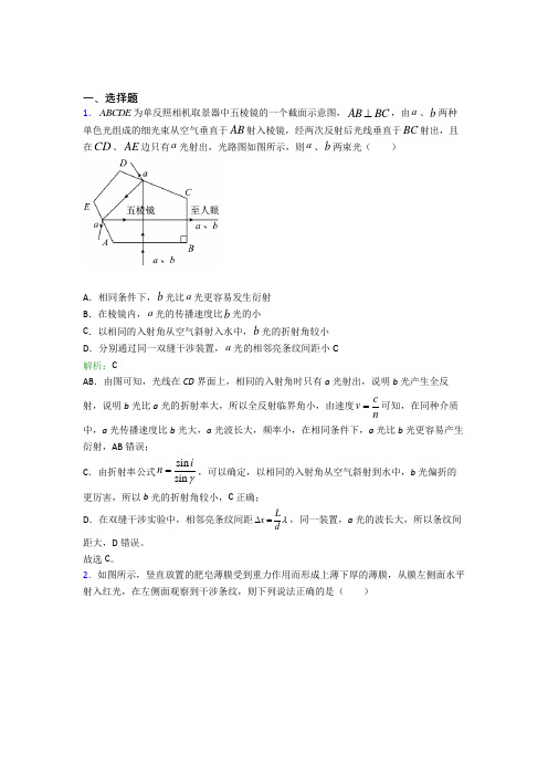
一、选择题1.ABCDE为单反照相机取景器中五棱镜的一个截面示意图,AB BC⊥,由a、b两种单色光组成的细光束从空气垂直于AB射入棱镜,经两次反射后光线垂直于BC射出,且在CD、AE边只有a光射出,光路图如图所示,则a、b两束光()A.相同条件下,b光比a光更容易发生衍射B.在棱镜内,a光的传播速度比b光的小C.以相同的入射角从空气斜射入水中,b光的折射角较小D.分别通过同一双缝干涉装置,a光的相邻亮条纹间距小C解析:CAB.由图可知,光线在CD界面上,相同的入射角时只有a光射出,说明b光产生全反射,说明b光比a光的折射率大,所以全反射临界角小,由速度cvn=可知,在同种介质中,a光传播速度比b光大,a光波长大,频率小,在相同条件下,a光比b光更容易产生衍射,AB错误;C.由折射率公式sinsininγ=,可以确定,以相同的入射角从空气斜射到水中,b光偏折的更厉害,所以b光的折射角较小,C正确;D.在双缝干涉实验中,相邻亮条纹间距Lxdλ∆=,同一装置,a光的波长大,所以条纹间距大,D错误。
故选C。
2.如图所示,竖直放置的肥皂薄膜受到重力作用而形成上薄下厚的薄膜,从膜左侧面水平射入红光,在左侧面观察到干涉条纹,则下列说法正确的是()A.干涉条纹是由薄膜左右两个面的反射光叠加形成的B.干涉条纹是红黑相间的竖直条纹C.入射光如果换成紫光,相邻亮条纹间距变大D.薄膜上不同颜色的光的条纹的明暗位置相同A解析:AA.干涉条纹是由薄膜左右两个面的反射光叠加形成的,A正确;B.干涉条纹是红黑相间的水平条纹,B错误;CD.光波的干涉条纹的间距公式Δlxd λ=入射光如果换成紫光则波长变短,相邻亮条纹间距变小,而且由于不同光的干涉条纹的间距不同,故不同颜色的光的条纹的明暗位置不相同,故CD错误;故选A。
3.一束由红光和紫光组成的复色光斜射到水平放置的平行矩形玻璃砖的上表面上的O 点,如图所示,入射光线与法线的夹角为i。
UL-752-BULLETINS-2006
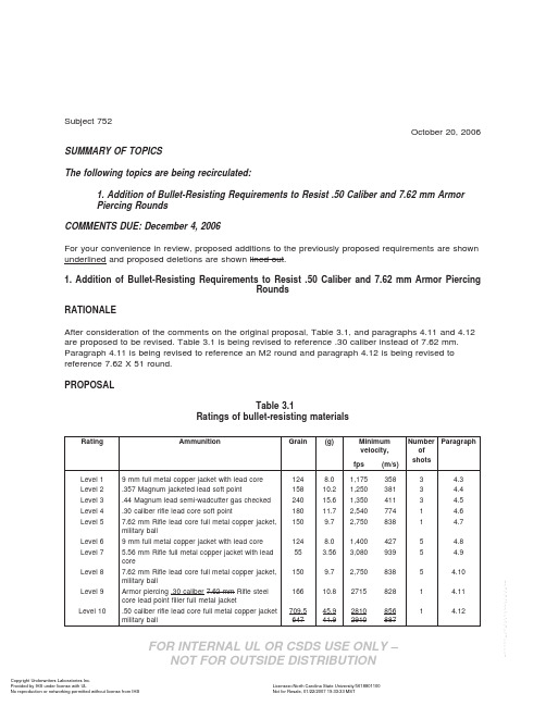
Subject752October20,2006 SUMMARY OF TOPICSThe following topics are being recirculated:1.Addition of Bullet-Resisting Requirements to Resist.50Caliber and7.62mm ArmorPiercing RoundsCOMMENTS DUE:December4,2006For your convenience in review,proposed additions to the previously proposed requirements are shown underlined and proposed deletions are shown lined-out.1.Addition of Bullet-Resisting Requirements to Resist.50Caliber and7.62mm Armor PiercingRoundsRATIONALEAfter consideration of the comments on the original proposal,Table3.1,and paragraphs4.11and4.12 are proposed to be revised.Table3.1is being revised to reference.30caliber instead of7.62mm. Paragraph4.11is being revised to reference an M2round and paragraph4.12is being revised to reference7.62X51round.PROPOSALTable3.1Ratings of bullet-resisting materialsRating Ammunition Grain(g)Minimumvelocity,NumberofshotsParagraphfps(m/s)Level19mm full metal copper jacket with lead core1248.01,1753583 4.3 Level2.357Magnum jacketed lead soft point15810.21,2503813 4.4 Level3.44Magnum lead semi-wadcutter gas checked24015.61,3504113 4.5 Level4.30caliber rifle lead core soft point18011.72,5407741 4.6 Level57.62mm Rifle lead core full metal copper jacket,military ball1509.72,7508381 4.7Level69mm full metal copper jacket with lead core1248.01,4004275 4.8 Level7 5.56mm Rifle full metal copper jacket with leadcore55 3.563,0809395 4.9Level87.62mm Rifle lead core full metal copper jacket,military ball1509.72,7508385 4.10Level9Armor piercing.30caliber7.62mm Rifle steelcore lead pointfiller full metal jacket16610.827158281 4.11Level10.50caliber rifle lead core full metal copper jacket military ball 709.564745.941.9281029108568871 4.12FOR INTERNAL UL OR CSDS USE ONLY –FOR INTERNAL UL OR CSDS USE ONLY –Table 3.1ContinuedRating Ammunition Grain (g)Minimumvelocity,Number of shots Paragraph fps(m/s)Supplementary shotgun 12-Gauge rifled lead slug and43728.31,5854833 4.1112-Gauge 00lead buckshot (12pellets)650421,200366NOTE –Maximum velocity is 110percent of the minimum velocity.4.11LEVEL 9–Protection against armor piercing rounds fired from an M1Garand rifle or the like,or high-power hunting and sporting rifles with muzzle energy of 2717to 2777foot-pounds (3683–4457J).The bullet will be a .30-06armor piercing round such as the US Military APM2.Protection against one shot from a military assault rifle,such as the M-14,and the like,with a muzzle energy of 2727to 3287foot-pounds (364–4457J).The bullet will be from a 7.62mm armor piercing round such as the US Military M2.4.12LEVEL 10–Protect against one shot from a military sniper rifle,such as the Barrett M82A1(XM107),with a muzzle energy of 12,439–12,706foot-pounds (16,863–20,404J).The bullet will be a .50caliber round such as the US Military M2.and the like,with a muzzle energy of 12,165to 14,720foot-pounds (16493–19957J).The bullet will be from a .50caliber round such as the US Military M33.Copyright ©2006Underwriters Laboratories Inc.OCTOBER 20,2006SUBJECT 752-2-。
本溪市初中物理九年级全册第十三章《内能》测试(答案解析)
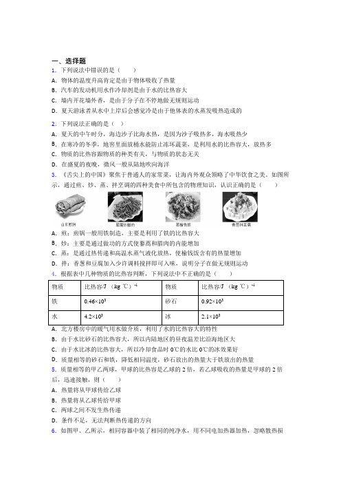
一、选择题1.下列说法中错误的是()A.物体的温度升高肯定是由于物体吸收了热量B.汽车的发动机用水作冷却剂是由于水的比热容大C.墙内开花墙外香,是由于分子在不停地做无规则运动D.夏天游泳者从水中上岸后会感觉冷是由于他体表的水蒸发吸热造成的2.下列说法正确的是()A.夏天的中午时分,海边沙子比海水热,是因为沙子吸热多,海水吸热少B.在寒冷的冬季,地窖里面放桶水能防止冻坏蔬菜,是利用水的比热容大,放热多C.物质的比热容跟物质的种类有关,与物质的状态无关D.在盛夏的夜晚,微风一般从陆地吹向海洋3.《舌尖上的中国》聚焦于普通人的家常菜,让海内外观众领略了中华饮食之美。
如图所示,通过煎、炒、蒸、拌烹调的四种美食中所包含的物理知识,认识正确的是()A.煎:煎锅一般用铁制造,主要是利用了铁的比热容大B.炒:主要是通过做功的方式使藜蒿和腊肉的内能增加C.蒸:是通过热传递和高温水蒸气液化放热,使榆钱饭含有的热量增加D.拌:香葱和豆腐加入少许调料搅拌即可入味,说明分子在做无规则运动4.根据表中几种物质的比热容判断,下列说法中不正确的是()物质比热容/J·(kg·℃)-1物质比热容/J·(kg·℃)-1铁0.46×103砂石0.92×103水 4.2×10³冰 2.1×103B.由于水比砂石的比热容大,所以内陆地区的昼夜温差比沿海地区大C.由于水比冰的比热容大,所以冷却食品时0℃的水比0℃的冰效果好D.质量相等的砂石和铁,降低相同温度,砂石放出的热量大于铁放出的热量5.质量相等的甲乙两球,甲球的比热容是乙球的2倍,若乙球吸收的热量是甲球的2倍后,迅速接触,则()A.热量将从甲球传给乙球B.热量将从乙球传给甲球C.两球之间不发生热传递D.条件不足,无法判断热传递的方向6.如图甲、乙所示,相同容器中装了相同的纯净水,用不同电加热器加热,忽略散热损失,得到如图丙所示的水温与加热时间的图像,下列说法正确的是()A.加热相同时间,两杯水吸收的热量相同B.吸收相同的热量,甲杯中水的末温比乙杯的高C.升高相同温度,甲杯中水吸热比乙杯的少D.相同时间内,甲杯中加热器放热比乙杯中的多7.对于图中所示的四幅图,下列说法中正确的是()A.甲图中软木塞飞出时,管内水蒸气的内能增加B.乙图中两个压紧的铅块能吊起钩码,说明分子间只存在引力C.丙图中活塞向下运动时,瓶内空气温度升高,属于内能转化为机械能D.丁图中小朋友下滑时,是通过做功增加了物体内能8.对下列现象的解释,正确的是()A.我们常常受到“二手烟”的危害,是因为分子在不停地做无规则运动B.封闭在容器内的液体很难被压缩,说明分子间有引力C.用手捏海绵,海绵的体积变小了,说明分子间有间隙D.铅笔笔芯用了一段时间后会变短,说明分子间有斥力9.对于图中所示的四幅图,下列说法中正确的是()A.甲图中两个压紧的铅块能吊起钩码,主要是因为分子间存在引力B.乙图中活塞向下运动与内燃机的做功冲程的能量转化相同C.丙图中小朋友下滑时,内能转化为机械能D.丁图中软木塞飞出时,管内水蒸气的内能增加10.根据表中的数据,下列判断正确的是()一些物质的比热容()J /kg C ︒⎡⎤⋅⎣⎦水 34.210⨯ 铝 30.8810⨯煤油、冰 32.110⨯ 干泥土 30.8410⨯ 沙石30.9210⨯铜30.3910⨯A .不同物质的比热容不可能相同B .夏天,在地上洒水会感到凉快,主要利用水的比热大的特性C .比较水和沙石的比热容可知,沿海地区比内陆地区昼夜温差大D .质量相等的铝块和铜块升高相同的温度,铝块吸收的热量多 11.关于温度、热量、内能之间的关系,下列说法正确的是( ) A .温度低的物体可能比温度高的物体内能多 B .物体内能增加,一定吸收了热量C .热量总是从内能大的物体传递给内能小的物体D .物体吸收热量,温度一定升高12.关于粒子和宇宙,下列说法正确的是( ) A .封闭在容器内的液体很难被压缩,说明分子间有引力 B .在质子、分子和原子中,尺度最小的是原子 C .用手捏海绵,海绵的体积变小了,说明分子间有间隙D .宇宙是一个有层次的天体结构体系,太阳属于银河系中的一颗恒星二、填空题13.用两个相同的“热得快”,分别给质量、初温都相同的甲、乙两种液体同时加热,两液体的温度随时间变化关系的图象如图。
系统化护理干预对呼吸内科重症患者的护理效果观察
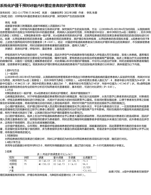
系统化护理干预对呼吸内科重症患者的护理效果观察发布时间:2021-11-17T00:55:36.849Z 来源:《健康世界》2021年19期作者:李凤朱蓉[导读] 目的:对呼吸内科重症患者实行系统化护理,探究其所产生的实际效果李凤朱蓉成都医学院第三附属医院.成都市郫都区人民医院611730摘要:目的:对呼吸内科重症患者实行系统化护理,探究其所产生的实际效果。
方法:以2020年4月-2021年4月为时间段,从我院病例信息管理系统中选取出58例呼吸内科中的重症患者,将其纳入实验研究范围,所有患者对半划分,其中29例归为A组(观察组),另外29例归为B组(对照组)。
对B组患者采用一般护理,对A组患者采用系统化护理,后就两组患者的预后效果及患者预前预后的各项指标进行对比。
结果:从两组患者的预后效果来看,A组患者的预后效果更佳,其护理总有效率极高,从两组患者的各项指标来看,A组患者均优于B 组,上述各方面两组间均存在显著差异(P<0.05)。
结论:对重症呼吸道疾病患者实行系统化护理所体现出的效果极好,不仅能够使患者的病情发展得到有效抑制,同时还能够促使患者康复的速度加快,值得大力推广。
关键词:系统化护理;呼吸内科;重症患者;实际效果呼吸系统作为气体交换的场所,与外界相通,因此外界空气中的病原体等均极易进入呼吸道从而引发感染,致使人体患病。
通常情况下,呼吸道疾病患者的症状主要体现为呼吸困难、精神不振等,更有甚者还会体现出呼吸衰竭等严重现象。
临床上单靠治疗无法促使患者的病情好转,只能在一定程度上缓解患者的症状,对此需辅以科学合理的护理措施,不仅可以巩固治疗效果,同时还能够抑制患者病情的发展,促使患者早日康复[1]。
现就系统化护理对患有此类疾病的患者所产生的实际临床效果进行分析探讨,具体报道为以下内容。
1.资料与方法1.1一般资料以2020年4月-2021年4月为时间段,从我院病例信息管理系统中筛选出58例患有呼吸道疾病的重症患者纳入实验研究范围,将其对半划分为两组,其29例作为A组(观察组),另外29例作为B组(对照组)。
- 1、下载文档前请自行甄别文档内容的完整性,平台不提供额外的编辑、内容补充、找答案等附加服务。
- 2、"仅部分预览"的文档,不可在线预览部分如存在完整性等问题,可反馈申请退款(可完整预览的文档不适用该条件!)。
- 3、如文档侵犯您的权益,请联系客服反馈,我们会尽快为您处理(人工客服工作时间:9:00-18:30)。
南京06年高考录取率75.21% 65人考上北
大清华
9月,随着中考、高考招生相继落幕,义务教育免杂费后的第一个新学期开学,昨天,市政府召开新闻发布会,总结了今年我市义务教育免收杂费和中等学校、高校招生录取情况。
今年,南京52万义务教育阶段学生秋季开学时全部享受政府免收杂费。
其中既包括本市户口的学生,也包括符合政策的外来务工人员子女;既涵盖了公办学校,也覆盖了民办学校。
免杂费范围之广在江苏省列于首位。
此外,2万多困难家庭学生获得助学金、助学券等形式的教育资助。
对他们而言,基本实现了义务教育“全免费”。
今年南京中考、高考招生录取情况也十分喜人。
初中升高中录取率继续稳居95%以上,70%的学生可以进入优质高中。
高考录取率超省均5个百分点,本科录取净增2000多人,高考成绩再度大幅攀升。
在昨天的新闻发布会上,南京市教育局财务处处长张明对有关情况,做了详细的介绍说明。
据了解,今年秋季开学时,南京义务教育实现了减免“提速”和助困“扩容”——52万义务教育阶段学生秋季开学普惠性享受政府免收杂费,2万多困难家庭学生义务教育基本实
现“全免费”。
今年全市累计新增投入6400万元,比原计划提前四年半,全面实行义务教育阶段学生免收杂费政策,惠及城乡521700名学生,每个学生全年可免交杂费170元-310元。
据介绍,凡符合省市规定,在南京接受义务教育的外来务工人员子女,无论其就读公办学校或者民办学校,也都同步享受减免。
在全省,只有南京将减免的范围惠及民办学校和外来务工人员子女。
此外,全市600多名特困职工家庭子女和800名就读中等职业学校的困难家庭学生,今年也首次获得减免和资助。
记者了解到,截至目前,南京已构建起多层次、多路径的“绿色助学通道”,共为67000多人次的困难家庭学生,减免学习费用累计达1500多万元,确保全市义务教育阶段适龄学生,不会因为贫困而失学。
据南京市招生办公室主任刘安康介绍,今年南京高考本、专科录取人数均比去年有所增加,高考成绩再创历史新高,录取率达%,高于省均个百分点。
今年我市报名参加高考人数为35333人,实际被各类高校录取26573人,本、专科录取人数分别为13834人和12739人,录取人数比去年增加2343人。
其中本科录取人数比去年增加2092人,本科录取率高于省均个百分点。
今年被提前录取到国内外知名大学的学生为483人,比去年净增260多人,录取人数比去年实现翻番,占全省60%以上。
其中,被北大、清华两所国内顶尖高校录取的学生共有65人。
被清华录取的保送生有27人,被北大录取的保送生有16人。
还有22人通过普通高考被清华、北大录取。
除了南京外国语学校、南师大附中、金陵中学、南京市一中4所老牌名校,其他几所学校也培养出了能考入北大、清华的学生,如宁海中学有3人被清华录取,6中有1人被清华录取,南师附中江宁分校有3人被清华录取,1人被北大录取,六合高级中学有2人被北大录取。
南京今年不仅一大批重点中学高考成绩喜传捷报,市直属的三所名校分校也势如“黑马”。
南外仙林分校、南师附中江宁分校、金陵中学河西分校今年本科达线率均超过50%。
此外,高淳、溧水等县本科达线人数均增长50%以上,昔日“洼地”今日明显崛起,城乡教育均衡的推进大见成效。
南京市招办透露,今年南京共有170多名学生被英国剑桥大学、美国宾夕法尼亚大学、美国格林奈尔学院、加拿大多伦多大学等国外名校录取。
今年1月份,仅被多伦多大学录取的南京学生就已有72名。
其中包括南外本部43人、南外仙林分校6人、南外中加班10人,其他学校13人。
加上英国剑桥等国外知名院校
录取的南京学生,到目前共有170多名。
多伦多大学的入学考试所涉及的内容五花八门。
以笔试为例,学生须在45分钟时间内完成一篇命题作文,从供学生选择的5个作文题可以看出,除了需要相当的英文水平外,还考察了学生课本以外的知识和发散性思维,比如“介绍一下你心目中南京最吸引人的景点”、“如果有机会与一个历史人物会面,你会选择谁?为什么?”
前来南京主持考试的多伦多大学招生办公室主任当·麦克米伦先生说,他发现中国的学生基础知识非常扎实。
参加考试的南外学生郭亨说,面试时考官很注重他简历上参加课外活动的情况,提的全是课本以外的多元化问题,这使他得以充分发挥优势。
南外学生电视台台长张璐也说,她只是围绕自己报考的管理专业谈了许多自己的看法,而考官对这些属于她自己的观点很感兴趣。
今年2月,南师附中江宁分校高二年级年仅17岁的学生王天晓被剑桥大学破格录取,成为剑桥大学年龄最小的学生之一。
王天晓接受记者采访时说,他当初只是抱着试试看的态度,没想到在两次笔试中分别获得第一轮第二名、第二轮第一名的成绩。
在最后一轮面试中,剑桥大学主考官对王天晓的基础能力、综合素养、潜力与素质给予了充分肯定,并同意他将原报考的经济学专业改为计算机专业。
他的老师透露,王天晓初中三年在数理化、计算机等竞赛中共取得了
50多个奖项,确实是个非常优秀的学生。
记者从新闻发布会上获悉,今年,我市初中毕业生升学报名人数78989人,成为近年生源“第二高峰年”。
截至目前,中招录取工作尚未全部结束,据不完全统计,今年高中阶段各类学校共录取75079人,升学率已达%.
普通高中录取37235人,师范、高职、中职、中专、中技及综合高中等录取37844人,普职比为:,连续四年基本保持在1:1左右。
由于今年全市各类中等学校招生计划充裕,所有考生只要志愿得当,服从调剂,就可以100%升入高中就学。
预计到录取全部结束,今年全市初中升学率将超去年,再攀历史新高。
目前,南京市星级以上普通高中52所,70%以上学生在优质高中就读,这一比例比2000年实现翻番。
南外仙林分校、南师附中江宁分校、金陵中学河西分校三所”民办航母学校”,经过三年发展,很快跻身优质高中行列。
同时,职业教育招生、就业两头旺。
目前,全市现有国家级重点职业学校17所,省级以上职业学校23所,省级示范专业38个,各色专业80多个门类,国家和省级紧缺人才基地10个、国家和省级实训基地7个。
南京职校毕业生就业率连续几年始终保持在95%以上,专业对口就业率超过90%,古籍修复、云锦等一大批专业就业率保持在100%。
金陵晚报·施教戚庆燕郝也。
