(最新)半导体器件参考
最新(施敏)半导体器件物理(详尽版)ppt
江西科技师范大学
半导体器件物理
金刚石结构
由两个面心立方结构 沿空间对角线错开四 分之一的空间对角线 长度相互嵌套而成。
硅(Si) 锗(Ge)
江西科技师范大学
半导体器件物理 大量的硅(Si)、锗 (Ge)原子靠共价键 结合组合成晶体,每 个原子周围都有四个 最邻近的原子,组成 正四面体结构, 。这 四个原子分别处在正 四面体的四个顶角上, 任一顶角上的原子各 贡献一个价电子和中 心原子的四个价电子 分别组成电子对,作 为两个原子所共有的 价电子对。
江西科技师范大学
a 3/2
半导体器件物理
例1-1
假使体心结构的原子是刚性的小球,且中心原子与立方体八个角落 的原子紧密接触,试算出这些原子占此体心立方单胞的空间比率。
解
江西科技师范大学
半导体器件物理
练习
假使面心结构的原子是刚性的小球,且面中心原子与 面顶点四个角落的原子紧密接触,试算出这些原子占此面 心立方单胞的空间比率。
E1
原子核
E2 E3
能级
电子受到原子核和其 他电子的共同作用。
轨道 电子云在空间分布几率最 大值,即轨道上,电子出现的几 率最大。
江西科技师范大学
半导体器件物理 晶体中的电子
制造半导体器件所用的材 料大多是单晶体。 单晶体是由原子按一定周 期重复排列而成,且排列 相当紧密,相邻原子间距 只有零点几个纳米的数量 级。 当原子间距很小时,原子间的电子轨道将相遇而交叠,晶体中每个原子 的电子同时受到多个原子核和电子(包括这个原子的电子和其他原子的 电子)作用。 电子不仅可以围绕自身原子核旋转,而且可以转到另一个原子周围,即 同一个电子可以被多个原子共有,电子不再完全局限在某一个原子上, 可以由一个原子转到相邻原子,将可以在整个晶体中运动。 江西科技师范大学
半导体器件性能测试实验数据处理示例及思考题参考答案
CX C C
本次实验中忽略分布电容 CS 的存在,认为 C X
CS ,下同。
图 5-1
3AX31 突变结结电容 C X (CT ) 与偏压 V 关系曲线②(双对数坐标③)
表 5-2
3DG12 缓变结结电容 C X 与偏压 V 关系 0.4 0.6 1.0 2.0 3.0 4.0 5.0
0,VBC 0 。
2、 集电极-发射极反向饱和电流太大时将破坏管子的正常使用,试问在实际电路设计中你 会采取哪些措施? 可增加集电极串联电阻,以达到限流作用,从而防止由于 I CE 0 过大而破坏管子的正常使 用。 3、 请写出用万用表测找 N-P-N 和 P-N-P 三极管各电极的步骤。 首先找到基极即最中间的引脚; 万用表电阻档的黑表笔(电源正极,下同)接到基极,红表笔(电源负极,下同)接到 基极以外的任意一个引脚,若导通(即电阻较小)则为 N-P-N 三极管,若不导通(即电 阻较大)则为 P-N-P 三极管; 万用表电阻档的红表笔接到基极以外的一个引脚上,黑表笔接到基极以外的另一个引脚 上,测量一次电阻,将红黑表笔位置对调后再测量一次电阻: 对于 N-P-N 三极管,电阻较小的一次测量时,黑表笔接的是集电极,红表笔接的是 发射极; 对于 P-N-P 三极管,电阻较小的一次测量时,黑表笔接的是发射极,红表笔接的是 集电极。
测试条件: C __ pF V/V C’’/pF CX/pF
CX C C
① ② ③
本实验中忽略分布电容的存在 因实验数据不准确,故此关系曲线不准确 双对数坐标指的是两个坐标轴的单位长度都是经过对数计算后的平面坐标系,建议使用 Origin 软件绘制 10 / 20
半导体器件性能测试实验 数据处理示例及思考题参考答案
《半导体器件》习题及参考答案
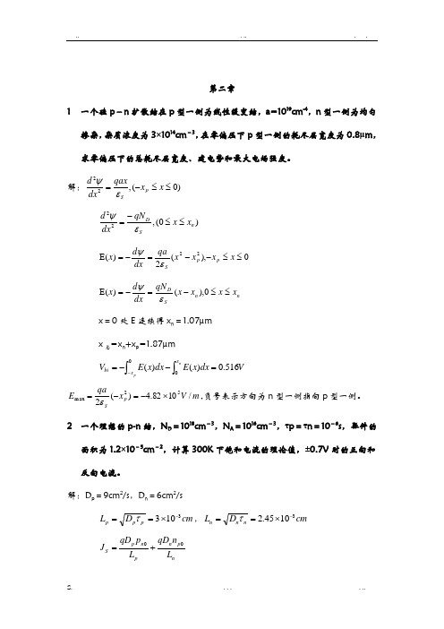
第二章1 一个硅p -n 扩散结在p 型一侧为线性缓变结,a=1019cm -4,n 型一侧为均匀掺杂,杂质浓度为3×1014cm -3,在零偏压下p 型一侧的耗尽层宽度为0.8μm ,求零偏压下的总耗尽层宽度、建电势和最大电场强度。
解:)0(,22≤≤-=x x qax dxd p S εψ)0(,22n S D x x qN dxd ≤≤-=εψ 0),(2)(22≤≤--=-=E x x x x qa dx d x p p Sεψ n n SDx x x x qN dx d x ≤≤-=-=E 0),()(εψ x =0处E 连续得x n =1.07µm x 总=x n +x p =1.87µm⎰⎰=--=-npx x bi V dx x E dx x E V 0516.0)()(m V x qa E p S/1082.4)(252max ⨯-=-=ε,负号表示方向为n 型一侧指向p 型一侧。
2 一个理想的p-n 结,N D =1018cm -3,N A =1016cm -3,τp =τn =10-6s ,器件的面积为1.2×10⁻⁵cm -2,计算300K 下饱和电流的理论值,±0.7V 时的正向和反向电流。
解:D p =9cm 2/s ,D n =6cm 2/scm D L p p p 3103-⨯==τ,cm D L n n n 31045.2-⨯==τnp n pn p S L n qD L p qD J 0+=I S =A*J S =1.0*10-16A 。
+0.7V 时,I =49.3µA , -0.7V 时,I =1.0*10-16A3 对于理想的硅p +-n 突变结,N D =1016cm -3,在1V 正向偏压下,求n 型中性区存贮的少数载流子总量。
设n 型中性区的长度为1μm ,空穴扩散长度为5μm 。
解:P +>>n ,正向注入:0)(20202=---pn n n n L p p dx p p d ,得:)sinh()sinh()1(/00pnn pn kTqV n n n L x W L x W e p p p ---=- ⎰⨯=-=nnW x n n A dx p p qA Q 20010289.5)(4一个硅p +-n 单边突变结,N D =1015cm -3,求击穿时的耗尽层宽度,若n 区减小到5μm ,计算此时击穿电压。
半导体器件物理施敏答案
半导体器件物理施敏答案【篇一:施敏院士北京交通大学讲学】t>——《半导体器件物理》施敏 s.m.sze,男,美国籍,1936年出生。
台湾交通大学电子工程学系毫微米元件实验室教授,美国工程院院士,台湾中研院院士,中国工程院外籍院士,三次获诺贝尔奖提名。
学历:美国史坦福大学电机系博士(1963),美国华盛顿大学电机系硕士(1960),台湾大学电机系学士(1957)。
经历:美国贝尔实验室研究(1963-1989),交通大学电子工程系教授(1990-),交通大学电子与资讯研究中心主任(1990-1996),国科会国家毫微米元件实验室主任(1998-),中山学术奖(1969),ieee j.j.ebers奖(1993),美国国家工程院院士(1995), 中国工程院外籍院士 (1998)。
现崩溃电压与能隙的关系,建立了微电子元件最高电场的指标等。
施敏院士在微电子科学技术方面的著作举世闻名,对半导体元件的发展和人才培养方面作出了重要贡献。
他的三本专著已在我国翻译出版,其中《physics of semiconductor devices》已翻译成六国文字,发行量逾百万册;他的著作广泛用作教科书与参考书。
由于他在微电子器件及在人才培养方面的杰出成就,1991年他得到了ieee 电子器件的最高荣誉奖(ebers奖),称他在电子元件领域做出了基础性及前瞻性贡献。
施敏院士多次来国内讲学,参加我国微电子器件研讨会;他对台湾微电子产业的发展,曾提出过有份量的建议。
主要论著:1. physics of semiconductor devices, 812 pages, wiley interscience, new york, 1969.2. physics of semiconductor devices, 2nd ed., 868 pages, wiley interscience, new york,1981.3. semiconductor devices: physics and technology, 523 pages, wiley, new york, 1985.4. semiconductor devices: physics and technology, 2nd ed., 564 pages, wiley, new york,2002.5. fundamentals of semiconductor fabrication, with g. may,305 pages, wiley, new york,20036. semiconductor devices: pioneering papers, 1003 pages, world scientific, singapore,1991.7. semiconductor sensors, 550 pages, wiley interscience, new york, 1994.8. ulsi technology, with c.y. chang,726 pages, mcgraw hill, new york, 1996.9. modern semiconductor device physics, 555 pages, wiley interscience, new york, 1998. 10. ulsi devices, with c.y. chang, 729 pages, wiley interscience, new york, 2000.课程内容及参考书:施敏教授此次来北京交通大学讲学的主要内容为《physics ofsemiconductor device》中的一、四、六章内容,具体内容如下:chapter 1: physics and properties of semiconductors1.1 introduction 1.2 crystal structure1.3 energy bands and energy gap1.4 carrier concentration at thermal equilibrium 1.5 carrier-transport phenomena1.6 phonon, optical, and thermal properties 1.7 heterojunctions and nanostructures 1.8 basic equations and exampleschapter 4: metal-insulator-semiconductor capacitors4.1 introduction4.2 ideal mis capacitor 4.3 silicon mos capacitorchapter 6: mosfets6.1 introduction6.2 basic device characteristics6.3 nonuniform doping and buried-channel device 6.4 device scaling and short-channel effects 6.5 mosfet structures 6.6 circuit applications6.7 nonvolatile memory devices 6.8 single-electron transistor iedm,iscc, symp. vlsi tech.等学术会议和期刊上的关于器件方面的最新文章教材:? s.m.sze, kwok k.ng《physics of semiconductordevice》,third edition参考书:? 半导体器件物理(第3版)(国外名校最新教材精选)(physics of semiconductordevices) 作者:(美国)(s.m.sze)施敏 (美国)(kwok k.ng)伍国珏译者:耿莉张瑞智施敏老师半导体器件物理课程时间安排半导体器件物理课程为期三周,每周六学时,上课时间和安排见课程表:北京交通大学联系人:李修函手机:138******** 邮件:lixiuhan@案2013~2014学年第一学期院系名称:电子信息工程学院课程名称:微电子器件基础教学时数: 48授课班级: 111092a,111092b主讲教师:徐荣辉三江学院教案编写规范教案是教师在钻研教材、了解学生、设计教学法等前期工作的基础上,经过周密策划而编制的关于课程教学活动的具体实施方案。
半导体器件 分立器件 大功率双极型晶体管空白详细规范-最新国标

半导体器件分立器件大功率双极型晶体管空白详细规范1 范围本空白详细规范规定了制定大功率双极型晶体管详细规范的基本原则,制定该范围内的所有详细规范应与本空白详细规范一致。
2 规范性引用文件下列文件中的内容通过文中的规范性引用而构成本文件必不可少的条款。
其中,注日期的引用文件,仅该日期对应的版本适用于本文件;不注日期的引用文件,其最新版本(包括所有的修改单)适用于本文件。
GB/T 4589.1-2006 半导体器件第10部分:分立器件和集成电路总规范( IEC60747-10:1991,IDT) GB/T 4937.3 半导体器件机械和气候试验方法第3部分:外部目检GB/T 4937.4 半导体器件机械和气候试验方法第4部分:强加速稳态湿热试验GB/T 4937.6-XXXX 半导体器件机械和气候试验方法第6部分:高温贮存GB/T 4937.9-XXXX 半导体器件机械和气候试验方法第9部分:标志耐久性GB/T 4937.12 半导体器件机械和气候试验方法第12部分:扫频振动GB/T 4937.14 半导体器件机械和气候试验方法第14部分:引出端强度(引线牢固性)GB/T 4937.15 半导体器件机械和气候试验方法第15部分:通孔安装器件的耐焊接热GB/T 4937.19 半导体器件机械和气候试验方法第19部分:芯片剪切强度GB/T 4937.21 半导体器件机械和气候试验方法第21部分:可焊性GB/T 4937.22 半导体器件机械和气候试验方法第22部分:键合强度GB/T 4937.23-2023 半导体器件机械和气候试验方法第23部分:高温工作寿命GB/T 4937.25-XXXX 半导体器件机械和气候试验方法第25部分:温度循环GB/T 4937.26 半导体器件机械和气候试验方法第26部分:静电放电(ESD)敏感度测试人体模型(HBM)GB/T 4937.27 半导体器件机械和气候试验方法第27部分:静电放电(ESD)敏感度测试机器模型(MM)GB/T 4937.30 半导体器件机械和气候试验方法第30部分:非密封表面安装器件在可靠性试验前的预处理GB/T 4937.31 半导体器件机械和气候试验方法第31部分:塑封器件的易燃性(内部引起的)GB/T 4937.32 半导体器件机械和气候试验方法第32部分:塑封器件的易燃性(外部引起的)GB/T 4937.34 半导体器件机械和气候试验方法第34部分:功率循环GB/T 4937.35 半导体器件机械和气候试验方法第35部分:塑封电子元器件的声学显微镜检查GB/T 7581 半导体分立器件外形尺寸GB/T 12560-202X 半导体器件分立器件分规范GJB 128 半导体分立器件试验方法GJB 10163-2021 塑封集成电路的潮湿敏感度分级试验方法3 要求3.1 总则本规范应与GB/T 12560一同使用。
【精品】半导体器件原理简明教程习题答案供参考
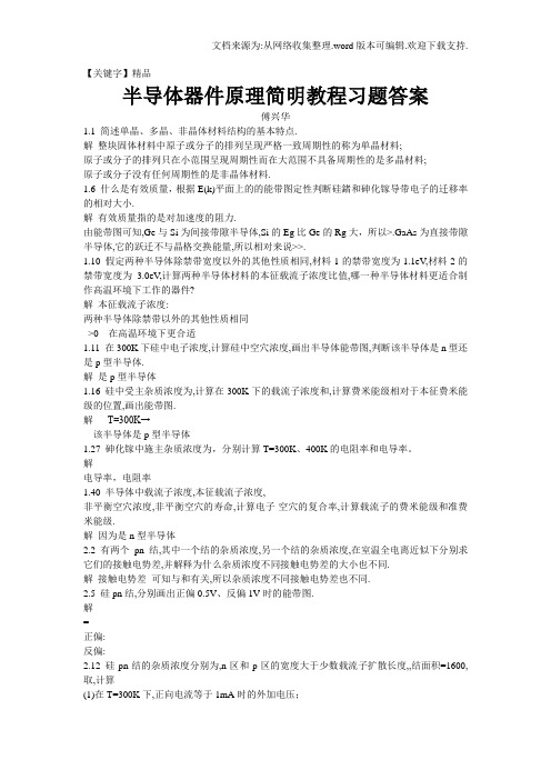
【关键字】精品半导体器件原理简明教程习题答案傅兴华1.1 简述单晶、多晶、非晶体材料结构的基本特点.解整块固体材料中原子或分子的排列呈现严格一致周期性的称为单晶材料;原子或分子的排列只在小范围呈现周期性而在大范围不具备周期性的是多晶材料;原子或分子没有任何周期性的是非晶体材料.1.6 什么是有效质量,根据E(k)平面上的的能带图定性判断硅鍺和砷化镓导带电子的迁移率的相对大小.解有效质量指的是对加速度的阻力.由能带图可知,Ge与Si为间接带隙半导体,Si的Eg比Ge的Rg大,所以>.GaAs为直接带隙半导体,它的跃迁不与晶格交换能量,所以相对来说>>.1.10 假定两种半导体除禁带宽度以外的其他性质相同,材料1的禁带宽度为1.1eV,材料2的禁带宽度为 3.0eV,计算两种半导体材料的本征载流子浓度比值,哪一种半导体材料更适合制作高温环境下工作的器件?解本征载流子浓度:两种半导体除禁带以外的其他性质相同>0 在高温环境下更合适1.11 在300K下硅中电子浓度,计算硅中空穴浓度,画出半导体能带图,判断该半导体是n型还是p型半导体.解是p型半导体1.16 硅中受主杂质浓度为,计算在300K下的载流子浓度和,计算费米能级相对于本征费米能级的位置,画出能带图.解T=300K→该半导体是p型半导体1.27 砷化镓中施主杂质浓度为,分别计算T=300K、400K的电阻率和电导率。
解电导率,电阻率1.40 半导体中载流子浓度,本征载流子浓度,非平衡空穴浓度,非平衡空穴的寿命,计算电子-空穴的复合率,计算载流子的费米能级和准费米能级.解因为是n型半导体2.2 有两个pn结,其中一个结的杂质浓度,另一个结的杂质浓度,在室温全电离近似下分别求它们的接触电势差,并解释为什么杂质浓度不同接触电势差的大小也不同.解接触电势差可知与和有关,所以杂质浓度不同接触电势差也不同.2.5 硅pn结,分别画出正偏0.5V、反偏1V时的能带图.解=正偏:反偏:2.12 硅pn结的杂质浓度分别为,n区和p区的宽度大于少数载流子扩散长度,,结面积=1600,取,计算(1)在T=300K下,正向电流等于1mA时的外加电压;(2)要使电流从1mA 增大到3mA,外加电压应增大多少?(3)维持(1)的电压不变,当温度 T 由300K 上升到400K 时,电流上升到多少? 解 (1) (2)... ...2.14 根据理想的pn 结电流电压方程,计算反向电流等于反向饱和电流的70%时的反偏电压值。
半导体器件基础习题答案(完美版)
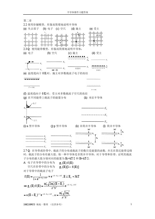
Dp
p
kT q
Dp
kT 0.0259eV p 1300cm 2 / V s q e
Q: (f) 低浓度注入的代数陈述是什么? A:
33.67cm 2 / s
p n0 , n n0 , n型半导体 n p0 , p p0 , p来产生过剩载流子。这些过剩载流子将会通过 R-G 中心复合形 式被复合。 说明:硅是间接半导体,在间接半导体中,R-G 中心复合机制是主要的复合过程,与 R-G 中心复合相比,直接复合是完全可以忽略的。 Q: (h) 在处理之前,硅样品中含有 ND=10^14/cm3 施主和 NT=10^11/cm3 R-G 中心。处理之 后, 样品含有 ND=10^17/cm3 施主和 NT=10^10/cm3 R-G 中心在处理的过程中少子的寿命 是增加了还是减少了?说明理由。 A: 少子寿命增加了。因为
半导体器件习题答案1062109053杨旭一整理仅供参考第二章22使用价键模型形象而简要地说明半导体温度趋向于0k时施主对多数载流子电子的冻结温度趋向于0k时受主对多数载流子空穴的冻结简并半导体27在导带或价带中载流子的分布或载流子的数目是能量的函数并且在靠近能带边缘时载流子的分布有最大值
半导体器件习题答案
半导体器件习题答案
A:clear; %specification of basic parameters kT=0.0259; ni=1.0e10; NB=logspace(13,18); EFiD=kT.*log(NB./ni); EFiA=-EFiD; %plot out Fermi level positioning
说明:当材料内存在电场时,能带能量变成位置的函数,称为“能带弯曲” Q: (b) 电子的动能为零,即 K.E.=0 A: 说明:
33B《半导体分立器件通用规范》与33A《半导体分立器件总规范》新旧标准变化梳理

50)明确了检验批在C组检验完成前才能交货。
51)附录E中关于器件结构相似的器件类型作了细分陈述;
5交货准备
1)增加了质量合格证说明;
6说明事项
1)该章对器件编号、质量等级、辐射加固保证等级、后缀字母作了详细说明;
2)增加了附录H《术语和定义》;
40)E2分组寿命试验明确了,该分组寿命项目不应与C6分组的寿命试验项目相同;对大功率器件,C组未进行间歇工作寿命试验,则E2分组应进行间歇工作寿命试验,抽样数45 (0);
41)E2分组寿命试验,对于功率型场效应晶体管应进行稳态反向偏置或稳态栅偏置;
42)E 3分组明确了试验项目为芯片粘附强度(适用于JP、JT和JCT级器件),抽样数3(0);
TA:环境或自由空气温度;
TC:壳温;
TOP:工作温度;
TSTG:贮存温度;
128B-2021半导体分立器件试验方法
3014电子元器件统计过程控制体系
3164半导体分立器件包装规范
3要求
1)将原第3章中对设计、结构和材料的要求调整到附录A中;
2)在原规范QPL认证的基础上,增加了QML认证方式;3)按通用规范供货的器件的芯片要求增加了规范性附录B《芯片的评价》4)辐射加固保证等级由原来4个等级增加到8个等级;5)增加了关于器件编号省略原则;
为稳态热阻。
半导体二极管:具有两个引出端并呈现非线性电压-电流特性的一种器件。
MOSFET:在每个栅极和沟道之间的绝缘层为氧化物材料的一种绝缘栅场效应晶体管。
高温反偏:描述施加阻断电压及通过外部加热一般在环境温度150℃下进行的筛选试
验。பைடு நூலகம்
半导体器件物理学参考答案(第三章)
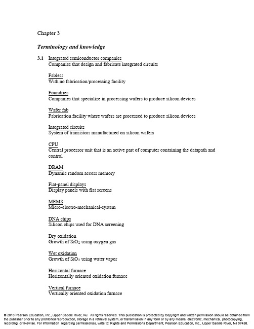
Chapter 3Terminology and knowledge3.1Integrated semiconductor companiesCompanies that design and fabricate integrated circuitsFablessWith no fabrication/processing facilityFoundriesCompanies that specialize in processing wafers to produce silicon devicesWafer fabFabrication facility where wafers are processed to produce silicon devicesIntegrated circuitsSystem of transistors manufactured on silicon wafersCPUCentral processor unit that is an active part of computer containing the datapath and controlDRAMDynamic random access memoryFlat-panel displaysDisplay panels with flat screensMEMSMicro-electro-mechanical-systemDNA chipsSilicon chips used for DNA screeningDry oxidationGrowth of SiO2 using oxygen gasWet oxidationGrowth of SiO2 using water vaporHorizontal furnaceHorizontally oriented oxidation furnaceVertical furnaceVertically oriented oxidation furnacePhotolithography/Optical lithographyProcess in which the resist is optically patterned and selectively removed from designated areas on a waferWafer stepperEquipment used in lithography processPhotoresistUltraviolet-light sensitive materialPhotomaskQuartz photo-plate containing a copy of pattern to be transferred to Si or SiO2 surfaceNegative resistPhotoresist that becomes polymerized and resistant to a developer when exposed to an UV lightPositive resistPhotoresist whose stabilizer breaks down when exposed to an UV light, leading to the preferential removal of exposed regions in a developerStripRemoval of photoresistAsherSystem that removes the resist on a wafer by oxidizing it in oxygen plasma or UV ozone systemLithography fieldSmall area exposed to an UV light during the exposure through a photomask and an optical reduction systemStepperAnother name for lithography equipmentStep-and-repeat actionThe process of exposing different parts of a wafer until the whole wafer has been exposedPhase-shift photomaskPhotomask that produces 180 degree phase difference in neighboring clear features so that their diffraction fringes cancel each otherOptical Proximity Correction (OPC)Printing a slightly different shape on the photomask to correct distortions resulting from an exposure processOverlayAlignment between 2 separate lithography stepsExtreme UV lithography (EUVL)Lithography that uses 13nm wavelength and is expected to result in much higher resolutionSoft-x-ray lithographyOld name of EUVLElectron-beam lithography (EBL)Lithography using a focused stream of electronsElectron projection lithography (EPL)EBL that exposes a complex pattern simultaneously using a mask and a reduction electron lens systemWet etchingRemoval of SiO2 using hydrofluoric acidIsotropicWithout preference in directionDry etching (also known as plasma etching or reactive-ion etching (RIE)) Removal of SiO2 using plasma and reactive ionsAnisotropicWith preference in directionSelectivityThe extent in which an etching process distinguishes between different materials End-point detectorDetector that monitors the emission of characteristic light from the etching products so as to signal when etching should endPlasma process induced damage / Wafer charging damageDamage to devices on wafers due to the use of plasmaAntenna EffectSensitivity of the damage to the size of the conductorIon implantationMethod of doping in which ions of impurity are accelerated and shot into thesemiconductor surfaceGas-source dopingMethod of doping in which a gas reacts with silicon and liberates phosphorus so that phosphorous diffuses into the silicon substrateSolid-source diffusionMethod of doping in which the dopants from the thin film coated on the siliconsurface diffuse into siliconAnnealHeating of wafers for dopant activation and damage removalDopant activationMaking dopants behave as donors and acceptors by heating the wafersImplantation doseTotal number of implanted ions/cm2Depth/ RangeThe location of peak concentration below the surface of siliconStraddleSpread of dopant concentration profile3.2 DiffusionThe movement of molecules from an area of high concentration to an area of low concentrationJunction depthThickness of diffusion layerDiffusivityConstant that describes how quickly a given impurity diffuses in silicon for a given furnace temperaturePredepositionPortion of diffusion process step with the source presentDrive-inPortion of diffusion process step without the sourceFurnace annealingHeating of wafers in a furnace for dopant activation and damage removalRapid thermal annealing (RTA)Annealing process in which a wafer is rapidly heated to high temperature and cooled quickly down to the room temperatureRapid thermal oxidationOxidation process in which a wafer is heated to the designated temperature quickly, oxidized, and then cooled rapidly down to the room temperatureRapid thermal chemical vapor deposition (CVD)Chemical vapor deposition process in which a wafer is heated to the designated temperature quickly, the material is deposited on the wafer, and the wafer is cooled rapidly down to the room temperatureLaser annealingAnnealing process in which a silicon wafer is heated with a pulsed laser Transient enhanced diffusion (TED)Diffusion phenomena in which diffusion rate is increased by crystal damage due to ion implantationInterconnectMetal connection between devices in integrated circuitsInter-metal dielectricsMaterials used for electrical isolation between metal layersCrystallineMolecular structure with nearly perfect periodicityPolycrystallineMolecular structure composed of densely packed crystallites or grains of single-crystalsAmorphousStructure with no atomic or molecular orderingGrain boundaryInterface between crystal grainsThin-film transistors (TFT)Transistors made of amorphous or polycrystalline silicon, widely used in flat-panel displaysSputtering targetThe source material for sputteringReactive sputteringSputtering accompanied by chemical reaction of sputtered ions. For example, Ti sputtered in nitrogen gas forms TiN film on the Si waferPhysical vapor deposition (PVD)Another name for sputteringStep coverage problemThe inability of sputtering to deposit uniform films in small holes or vertical features on waferHigh-temperature oxide (HTO)Very conformal oxide formed by a CVD process at a high temperatureLow-pressure chemical vapor deposition (LPCVD)CVD process at low pressure, which yields good thickness uniformity and low gas consumptionPlasma-enhanced chemical vapor deposition (PECVD)CVD using plasma; low deposition temperaturesIn-situ dopingDoping process in which dopant species are introduced during the CVD deposition of polycrystalline siliconSpin-onProcess in which liquid materials are spun onto the waferEpitaxySpecial type of thin-film deposition technology that produces a crystalline layer on silicon surfaces that is an extension of the underlying semiconductor crystal arrangementMetallizationInterconnection of individual devices by metal linesVia/ PlugElectrical connection between adjacent metal layersElectromigrationMigration of metal along the crystal-grain boundaries in a quasi-random manner, causing voids to occur in metal interconnectsDamascene processProcess used to form copper interconnect linesChemical-mechanical polishing (CMP)Process in which a polishing pad and slurry are used to polish away material and leave a very flat surfaceBack-end processMetallization; last step of IC fabricationFront-end processesOxidation, diffusionPlanarizationProcess to obtain a flat surface to improve lithography and etchingMulti-chip modulesMultiple chips put into one packageSolder bumpsElectrical connection between chip and packageFlip-chip bondingMelting pre-formed solder bumps on IC pads to make all connectionssimultaneouslyBurn-inSubjecting IC packages to higher than normal voltage and temperatures; identify potential failuresQualificationRoutine used to verify the quality of manufacturing and reliabilityOperation life testPart of qualification process; to find out if the devices last over one thousandoperating hours3.3 (a) Lithography fieldA small area having the best optical resolution (The beam intensity is uniformwithin a lithography field.)(b) M isalignmentLayer to layer mismatch (Each new mask level should be aligned to one of theprevious levels)(c) SelectivityThe ratio of etching rate of the film to be etched to that of the substrate filmbelow(d) End-point detectionDetecting the exposed substrate film after the removal of the desired film.(e) Step coverageThe ratio of film thickness deposited on the flat surface to that deposited on thenon-flat surface.(f) ElectromigrationThe movement of atoms in a metal film due to momentum transfer from theelectrons carrying the current.3.4 (a) Wet. Otherwise, it would take too long to grow the thick oxide.(b) Dry because it provides better control of the gate (channel) length and verticalwall profile.(c) Arsenic because- it is a donor ion (group V),- it reduces R p and ∆R p, and- it reduces diffusivity.(d) PECVD(e) Sputtering, dry etching, plasmas containing chlorine.(f)Oxidation3.5 Wet oxidation is faster than dry oxidation because the solid solubility of H 2O steaminto SiO 2 is higher than that of O 2 gas into SiO 2. This creates a very sharpconcentration profile that causes H 2O to diffuse towards the SiO 2-Si interface muchmore effectively than O 2 under the same conditions.3.6 (a) hr hrum um um um um 239.6/0117.02.0*165.02.0*2.02=+=τSolving the given equation for t ox and using quadratic formula,um t B A A T ox 256.02)(42=+++-=τ. (b) Linear approximation: )(τ+≈t AB T ox => 0.655um (156% error). Quadratic approximation: => 0.320um (25% error). )(2τ+≈t B T oxIn this case , neither linear nor quadratic approximations would bevalid.ox T A ≈Deposition3.7 Poly Silicon:SiH 4 → Si(s) + 2H 2Silicon Nitride:3SiH 2Cl 2 + 4NH 3 → Si 3N 4 + 6HCl + 6H 2LTO:SiH 4 + O 2 → SiO 2 + 2HCl + 2H 2HTO:SiH 2Cl 2 + 2H 2O → SiO 2 + 2HCl + 2H 2Diffusion3.8 (a) )(Dt Dt x x Dt x j j j ∆+=∆+⇒=())()(222Dt x Dt Dt x x x x j j j j j ∆+=∆+=∆+∆+())(2Dt x x x j j j ∆=∆+∆Since ,j j x x ∆>>j j j j x Dt x Dt x x 2)()(2∆≈∆⇒∆≈∆. (b) For boron,D (500K) = 10.5⨯Exp[-3.69/(8.614⨯10-5⨯773)]cm2/sec = 9.0⨯10-24 cm 2/sec, and500 years = 1.58⨯1010 sec.Hence,m cm x j μ9131042.11042.1--⨯=⨯=∆.Our assumption (j j x x ∆>>) in part (a) is correct.3.9 (a) Junction depth is distance from surface where the dopant concentration equalsthe substrate concentration.31510-===cm N N N junction d sub (Required junction dopant concentration) From Eq. (3.6.1),31540102--==cm e DtN N Dt x junction j π UsingeV E and cm N cm D e D D a kT E a 7.3,10sec,/5.10,215020/0====--,cm X j 41097.1-⨯=.(b) X j has the form2/1ln 2⎥⎦⎤⎢⎣⎡⎪⎪⎭⎫ ⎝⎛=Dt k Dt X j . Taking the derivative,j j j X Dt X Dt k Dt k Dt dDt dX 12ln 21ln 12/12/1-=⎪⎪⎭⎪⎪⎬⎫⎪⎪⎩⎪⎪⎨⎧⎥⎦⎤⎢⎣⎡⎪⎪⎭⎫ ⎝⎛-⎥⎦⎤⎢⎣⎡⎪⎪⎭⎫ ⎝⎛=. 14491039.91098.11102---⨯=⨯-⨯⨯=cm 101.98dDt dX -4j ()()240637370.310996.3360010.5.10cm eDt --⨯==∆ Hence, .01075.3.35≈⨯=∆∂∂=∆-cm Dt Dt X X j jVisualization3.10 (a) (b) 1.0μm resist Silicon substrate 1.0μm oxide 1.0μm oxide Silicon substrate(c) (d) 1.0μm oxide 1.0μm resist Silicon substrateSilicon substrate 1.0μm oxide3.11Contact 2 MaskContact 1 MaskChanging the polarity of the contact 1 mask results in the same cross section as problem 3.10 (d). The same cross-section is obtained by using a negative resist and the reversed mask of contact 1, which is opaque in the inside of contact 1 area.。
半导体器件物理学参考答案(第八章)
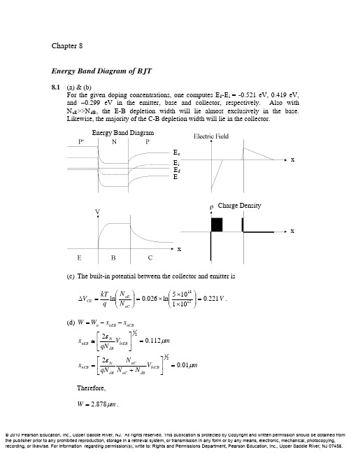
8.3
(a) N+: Emitter E f,n+ E f,p P: Base V BE is forward biased and V BC is reverse biased. N: Collector
E f,n
(b)
P
N
P
EMITTER
BASE
COLLECTOR
The P,N,P on the diagram refer to the minority carrier type in each region. The horizontal dotted lines refer to the equilibrium minority concentration (i.e. p N0 , n P0 ). The remaining dotted curves correspond to the excess minority carrier concentrations. Assumptions made here: W E & W B are shorter than the diffusion lengths of the holes & electrons respectively, resulting in a linear decay of excess minority carriers in the emitter and base. You should also notice that the scale for the yaxis differs for each region. (c) Base current consists of injection of holes into the emitter and recombination with a very small part of the collector current (remember that I E ~ I C ). The collector current consists almost entirely of electrons emitted from the forwardbiased BE junction which travel across the CB junction. Incidentally, an easy way to remember how a BJT works is to associate the names emitter and collector with the physical emission and collection of the minority electrons in the base.
最新电力电子半导体器件(GTO)

§6.1 GTO结构及工作原理
Gate Turn-off Thyristor——GTO
一、结构:四层PNPN结构,三端器件;
特点: ① α1 <α2 P1N1P2管不灵敏, N1P2N2管灵敏。 ②α1 +α2略大于1;器件 工作于临界饱和状态, 使关断成为可能。
③多元集成结构,由数 百个小GTO元并联形成。
4. dv/dt和di/dt
① dv/dt :
静态dv/dt 指GTO阻断时所能承受的最大电压上升率,过高 会使GTO结电容流过较大的位移电流,使α增大,印发误导通。 结温和阳极电压越高,GTO承受静态dv/dt 能力越低;门极反偏 电压越高,静态dv/dt 耐量越高。(并联电阻)
动态dv/dt 也称重加dv/dt ,是GTO在关断过程中阳极电压的 上升率。重加dv/dt 会使瞬时关断损耗增大,也会导致GTO损坏。
放大门极GTO 掩埋门极GTO 逆导GTO MOS—GTO 光控GTO
§6.2 特性与参数
一、静态特性 1.阳极伏安特性
*减小温度影响,可在门极与阴极间并一个电阻
定义:正向额定电压为90%VDRM 反向额定电压为90%VRRM
毛刺电流
2.通态压降特性 通态压降越小,通态损耗越小
3.安全工作区 与GTR和功率MOSFET不同,门极加正触发信号时(正向
偏置),无安全工作区问题,只有瞬时浪涌电流的规定值。 当门极加负脉冲关断信号时(反向偏置),有安全工作区
问题。 定义:在一定条件下,GTO能可靠关断的阳极电流与阳极电 压的轨迹。与门极驱动电路和缓冲电路参数有关。
二、动态特性
1.开通特性:
开通时间:ton = td + tr
半导体器件 分立器件 整流二极管-最新国标
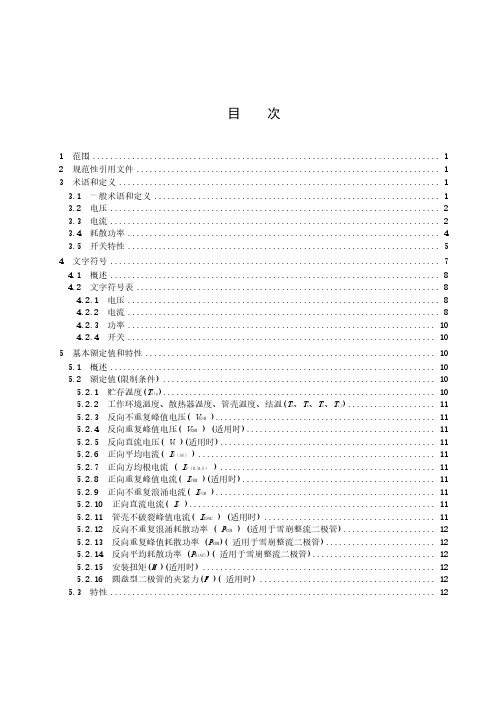
目次1 范围 (1)2 规范性引用文件 (1)3 术语和定义 (1)3.1 一般术语和定义 (1)3.2 电压 (2)3.3电流 (2)3.4耗散功率 (4)3.5开关特性 (5)4 文字符号 (7)4.1 概述 (8)4.2 文字符号表 (8)4.2.1 电压 (8)4.2.2 电流 (8)4.2.3 功率 (10)4.2.4 开关 (10)5 基本额定值和特性 (10)5.1 概述 (10)5.2 额定值(限制条件) (10)5.2.1 贮存温度(T stg) (10)5.2.2 工作环境温度、散热器温度、管壳温度、结温(T a、T s、T c、T vj) (11)5.2.3 反向不重复峰值电压( V RSM) (11)5.2.4 反向重复峰值电压( V RRM) (适用时) (11)5.2.5 反向直流电压( V R)(适用时) (11)5.2.6 正向平均电流( I F(AV)) (11)5.2.7 正向方均根电流( I F(R.M.S)) (11)5.2.8 正向重复峰值电流( I FRM)(适用时) (11)5.2.9 正向不重复浪涌电流( I FSM) (11)5.2.10 正向直流电流( I F) (11)5.2.11 管壳不破裂峰值电流( I RSMC) (适用时) (11)5.2.12 反向不重复浪涌耗散功率( P RSM) (适用于雪崩整流二极管) (12)5.2.13 反向重复峰值耗散功率(P RRM)( 适用于雪崩整流二极管) (12)5.2.14 反向平均耗散功率(P R(AV))( 适用于雪崩整流二极管) (12)5.2.15 安装扭矩(M)(适用时) (12)5.2.16 圆盘型二极管的夹紧力(F)( 适用时) (12)5.3 特性 (12)5.3.1 概述 (12)5.3.2 正向电压( V F ) (12)5.3.3 正向峰值电压( V FM )(适用时) (12)5.3.4 击穿电压( V( BR ) )(适用于雪崩整流二极管) (12)5.3.5 反向直流电流( I R(D) ) (12)5.3.6 反向重复峰值电流( I RRM ) (适用时) (12)5.3.7 恢复电荷( Q r )(适用时) (12)5.3.8 总电容电荷( Q C )(适用时) (13)5.3.9 反向恢复峰值电流( i rrm )(适用时) (13)5.3.10 反向恢复时间( t rr )(适用时) (13)5.3.11 反向恢复损耗(E rr) (适用时) (13)5.3.12 正向恢复时间( t fr )(适用时) (13)5.3.13 正向恢复峰值电压( V FRM )(适用时) (13)5.3.14 反向恢复软[度]因子( S rr )(适用时) (14)5.3.15 热阻( R th) (14)5.3.16 瞬态热阻抗(Z th (t))(适用时) (14)6 测量和试验方法 (14)6.1 电特性测量方法 (14)6.1.1 概述 (14)6.1.2 正向电压(V F、V FM) (14)6.1.3 雪崩整流二极管的击穿电压(V(BR)) (17)6.1.4 反向电流(I R) (18)6.1.5 反向重复峰值电流(I RRM ) (19)6.1.6 恢复电荷、反向恢复时间、反向恢复损耗和反向恢复软[度]因子(Q r,t rr、E rr、S rr) (20)6.1.7 正向恢复时间和正向恢复峰值电压(t fr,V frm) (24)6.1.8 总电容电荷(Q C) (26)6.2 热特性测量方法 (27)6.2.1 概述 (27)6.2.2 热阻(R th(j-r))和瞬态热阻抗(Z th(j-r)(t)) (27)6.3 额定值(极限值)的验证试验方法 (29)6.3.1 正向不重复浪涌电流(I FSM) (29)6.3.2 反向不重复峰值电压( V RSM ) (30)6.3.3 雪崩整流二极管的反向峰值功率(重复或不重复的)(P RRM、P RSM) (31)6.3.4 管壳不破裂峰值电流(I RSCM) (35)7 型式试验、例行试验和耐久性试验的要求,整流二极管的标志 (36)7.1 型式试验 (36)7.2 例行试验 (36)7.3 测量和试验方法 (37)7.4 整流二极管的标志 (37)7.5 耐久性试验 (37)7.5.1 耐久性试验表 (37)7.5.2 耐久性试验条件 (37)7.5.3 耐久性试验判定接收的特性和接收判据 (37)7.5.4 可靠性试验判定接收的特性和接收判据 (38)图1 正向恢复期间的电压波形,规范的方法Ⅰ (5)图2 正向恢复期间的电压波形,规范的方法Ⅱ (5)图3 反向恢复期间的电流波形 (6)图4 二极管关断时电压、电流及恢复电荷 (7)图5 反向电压额定值 (8)图6 正向电流额定值 (9)图7 恢复电荷Q r,反向恢复峰值电流I rrm,反向恢复时间t rr(理想特性曲线) (13)图8 正向电压的测试电路(直流法) (15)图9 正向电压的测试电路(交流法) (16)图10 通态电压与电流特性的关系图 (16)图11 正向电压的测试电路(脉冲法) (17)图12 击穿电压的测试电路 (18)图13 反向电流测试电路 (19)图14 反向峰值电流的测试电路 (19)图15 恢复电荷的测试电路(正弦半波法) (20)图16 测试恢复电荷时通过二极管 D 的电流波形(正弦半波法) (21)图17 恢复电荷的测试电路(矩形波法) (22)图18 测试恢复电荷时通过二极管 D 的电流波形(矩形波法) (23)图19 正向恢复时间的测试电路 (24)图20 测量正向恢复时间的电流波形 (25)图21 测量正向恢复时间的电压波形 (25)图22 总电容电荷的测试电路 (26)图23 热阻抗测试电路 (27)图24 在低测量电流I2下正向电压V F随外壳温度T c的典型变化的校准曲线(从外界加热时,即T c=T vj) (28)图25 正向浪涌(非重复)电流的测试电路 (29)图26 反向不重复峰值电压的测试电路 (31)图27 雪崩整流二极管的反向峰值功率的测试电路 (32)图28 反向电流波形(三角波法) (32)图29 反向电流波形(正弦波法) (33)图30 反向电流波形(矩形波法) (33)图31 反向功率P RSM与击穿电压的关系 (34)图32 管壳不破裂峰值电流的测试电路 (35)图33 通过受试器件的反向电流i R波形 (35)表1 电压文字符号 (8)表2 电流文字符号 (9)表3 功率文字符号 (10)表4 开关文字符号 (10)表5 整流二极管的型式试验和例行试验的最少试验项目 (37)半导体器件第2部分:分立器件整流二极管1 范围本文件给出了下列各类或各分类整流二极管的标准,包括:——一般整流二极管;——雪崩整流二极管;——快开关整流二极管;——肖特基势垒二极管。
《半导体器件》习题与参考答案
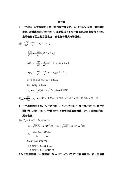
第二章1 一个硅p -n 扩散结在p 型一侧为线性缓变结,a=1019cm -4,n 型一侧为均匀掺杂,杂质浓度为3×1014cm -3,在零偏压下p 型一侧的耗尽层宽度为0.8μm ,求零偏压下的总耗尽层宽度、建电势和最大电场强度。
解:)0(,22≤≤-=x x qax dxd p S εψ)0(,22n SD x x qN dx d ≤≤-=εψ 0),(2)(22≤≤--=-=E x x x x qa dx d x p p Sεψ n n SDx x x x qN dx d x ≤≤-=-=E 0),()(εψ x =0处E 连续得x n =1.07µm x 总=x n +x p =1.87µm⎰⎰=--=-npx x bi V dx x E dx x E V 0516.0)()(m V x qa E p S/1082.4)(252max ⨯-=-=ε,负号表示方向为n 型一侧指向p 型一侧。
2 一个理想的p-n 结,N D =1018cm -3,N A =1016cm -3,τp =τn =10-6s ,器件的面积为1.2×10⁻⁵cm -2,计算300K 下饱和电流的理论值,±0.7V 时的正向和反向电流。
解:D p =9cm 2/s ,D n =6cm 2/scm D L p p p 3103-⨯==τ,cm D L n n n 31045.2-⨯==τnp n pn p S L n qD L p qD J 0+=I S =A*J S =1.0*10-16A 。
+0.7V 时,I =49.3µA , -0.7V 时,I =1.0*10-16A3 对于理想的硅p +-n 突变结,N D =1016cm -3,在1V 正向偏压下,求n 型中性区存贮的少数载流子总量。
设n 型中性区的长度为1μm ,空穴扩散长度为5μm 。
解:P +>>n ,正向注入:0)(20202=---pn n n n L p p dx p p d ,得:)sinh()sinh()1(/00pnn pn kTqV n n n L x W L xW e p p p ---=- ⎰⨯=-=nnW x n n A dx p p qA Q 20010289.5)(4一个硅p +-n 单边突变结,N D =1015cm -3,求击穿时的耗尽层宽度,若n 区减小到5μm ,计算此时击穿电压。
半导体器件芯片常用型号参数特性解析大全(精)
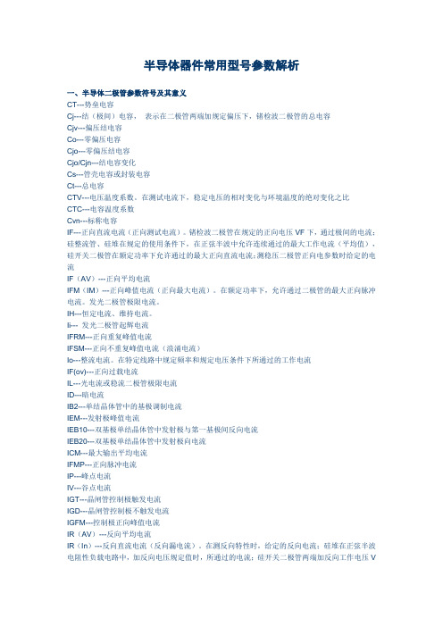
半导体器件常用型号参数解析一、半导体二极管参数符号及其意义CT---势垒电容Cj---结(极间)电容,表示在二极管两端加规定偏压下,锗检波二极管的总电容Cjv---偏压结电容Co---零偏压电容Cjo---零偏压结电容Cjo/Cjn---结电容变化Cs---管壳电容或封装电容Ct---总电容CTV---电压温度系数。
在测试电流下,稳定电压的相对变化与环境温度的绝对变化之比CTC---电容温度系数Cvn---标称电容IF---正向直流电流(正向测试电流)。
锗检波二极管在规定的正向电压VF下,通过极间的电流;硅整流管、硅堆在规定的使用条件下,在正弦半波中允许连续通过的最大工作电流(平均值),硅开关二极管在额定功率下允许通过的最大正向直流电流;测稳压二极管正向电参数时给定的电流IF(AV)---正向平均电流IFM(IM)---正向峰值电流(正向最大电流)。
在额定功率下,允许通过二极管的最大正向脉冲电流。
发光二极管极限电流。
IH---恒定电流、维持电流。
Ii--- 发光二极管起辉电流IFRM---正向重复峰值电流IFSM---正向不重复峰值电流(浪涌电流)Io---整流电流。
在特定线路中规定频率和规定电压条件下所通过的工作电流IF(ov)---正向过载电流IL---光电流或稳流二极管极限电流ID---暗电流IB2---单结晶体管中的基极调制电流IEM---发射极峰值电流IEB10---双基极单结晶体管中发射极与第一基极间反向电流IEB20---双基极单结晶体管中发射极向电流ICM---最大输出平均电流IFMP---正向脉冲电流IP---峰点电流IV---谷点电流IGT---晶闸管控制极触发电流IGD---晶闸管控制极不触发电流IGFM---控制极正向峰值电流IR(AV)---反向平均电流IR(In)---反向直流电流(反向漏电流)。
在测反向特性时,给定的反向电流;硅堆在正弦半波电阻性负载电路中,加反向电压规定值时,所通过的电流;硅开关二极管两端加反向工作电压VR时所通过的电流;稳压二极管在反向电压下,产生的漏电流;整流管在正弦半波最高反向工作电压下的漏电流。
