rmg8862c2说明书
超规直接接触式光学测量秤使用说明书

Scale Accuracy: 0.0002” (0.005mm)
Microscope Magnification: 40X
Smallest Scale Division: 0.001” (0.02mm)
(Both English and Metric scales are direct reading.)
INSTRUCTION MANUAL
SUPER GAGE
DIRECT CONTACT OPTICAL MEASURING SCALE
115 HOLMES ROAD • YPSILANTI MICHIGAN 48198-3020 (800) 321-9026 • (734) 483-8228 • Fax:(734) 483-9879
SUPER GAGE optics provide a wide field of view that is distortion-free; the scale is accurate to 0.0002”. The cast aluminum base is free from warp and capable of withstanding years of constant daily use.
(2.0000”)
(7.5190”) Figure 1. Examples of SUPER GAGE Microscope Readings
香港可铭电脑裁床产品说明书

电脑裁床电脑裁床是服装业裁剪技术的一大革新,它利用档案数据来控制刀的转动方向而生产所需要的裁片。
电脑裁床的高效使用还必须配有电脑拉布机,电脑吊挂系统等硬件和服装设计系统等软件的支持,这些设备所组成的系统为制衣企业的生产环节提供了完美的解决方案;目前电脑裁床型号有GT5250和GT7250,早在十几年前它是个很难想象的现实,但是随着时代的发展计算机技术越来越多的用于各行各业。
服装业不甘落后,也在慢慢的革新以适应激烈的国际竞争。
电脑裁床就是革新之一,并逐渐被各大服装企业所关注。
自动裁床可以说是样板房与裁剪房的完美结合。
这个相当完善的柔性化系统能够最大限度活用各种CAD设计的服装数据。
高度集成自动化、软件、面料裁切等技术,自动化完成打版、排料、铺布与裁剪的全过程。
最有经验的裁剪师也不能100%保证稳定的裁剪质量。
高技术的裁刀设计可以确保面料第一层与最后一层完全相同的裁剪质量。
根据面料的不同特点,裁剪方案设定不同参数进行裁剪,从而大大提高裁剪效率,节省耗电。
通过分析生产数据,模拟不同的生产情况,给出最佳排料组合,提供裁剪成本分析资料,计算铺布和裁剪时间,准确估计布料需求量,为正确的采购决策和工作量分配打下基础。
表面上看,自动裁床只不过是一个复杂的、特殊的绘图仪用多层布料代替纸,用钻头、刀具等特殊工具代替笔而已。
事实上,自动裁床是一个复杂的系统,配有计算机和相应的程序。
与CAD设计系统的连接方式不同品牌可能有所不同,但原理上是一致的,CAD设计系统与自动裁床交流的仅仅是数据(通常称为cutfile--CAD的设计系统中输出而被裁床接收的文件)。
而在同品牌CAD与裁床之间,有的是裁床程序直接读取样片信息和排版信息。
因此,通过端口连接、局域网连接甚至直接用软盘都可以转移文件,方法多样且便捷。
裁床优势:采用固定式裁剪台,可完成所有作业流程;裁剪区域采用刚毛垫式,寿命可达6-8年,大大降低耗材成本;采用分段吸附和分段裁剪方式,可同时分段进行裁剪、捡料、铺料作业;采用上下移动式刀片裁剪,精度高、速度快,耗材成本低;设备配有自我诊断功能(发生故障时,屏幕自动提示);采用轮式磨刀石,磨出刀口均匀一致,保证裁剪精度,提高裁剪速度;磨刀时间间隔可以根据面料自由调节、设定;软件控制裁剪过程,刀速可根据裁剪弧度、直线时自动调整,以达到高精度裁剪;无需垫纸即可保证高精度裁剪,降低耗材成本;设备操作更具人性化,操作简单、方便;机身每个分段区域旁有两个警示灯装置:裁剪完毕区域警示灯会自动亮起,机头不会移动到警示灯亮起的区域,确保工作人员在该区域内的安全操作;机头两边装有黄色安全杆:当操作人员不小心接触到黄色安全杆时,机头会自动停下,防止机头碰撞到工作人员,以确保操作人员安全。
RMG88.62C2控制盒复位及故障诊断
昆山威如机电设备有限公司
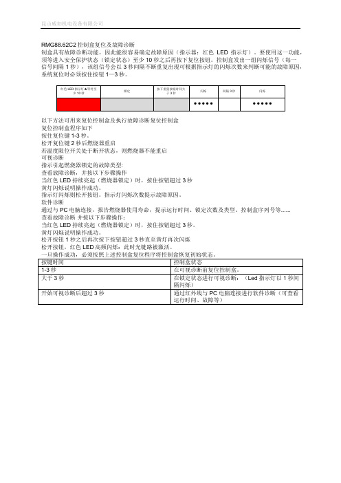
RMG88.62C2控制盒复位及故障诊断
制盒具有故障诊断功能,因此能很容易确定故障原因(指示器:红色LED指示灯)。
要使用这一功能,须等进入安全保护状态(锁定状态)至少10秒之后再按下复位按钮。
控制盒发出一组闪烁信号(每一
信号间隔1秒),该组信号会以3秒间隔不断重复出现可根据指示灯的闪烁次数来判断可能的故障原因,系统复位时必须按住按钮1—3秒。
以下方法可用来复位控制盒及执行故障诊断复位控制盒
复位控制盒程序如下
按住复位键1-3秒。
松开复位键2秒后燃烧器重启
若温度限位开关处于断开状态,则燃烧器不能重启
可视诊断
指示引起燃烧器锁定的故障类型:
查看放障诊断,并按以下步骤操作
当红色LED持续亮起(燃烧器锁定)时,按住按钮超过3秒
黄灯闪烁说明操作成功。
指示灯闪烁则松开按钮。
指示灯闪烁次数提示故障原因。
软件诊断
通过与PC电脑连接,报告燃烧器使用寿命,提示运行时间、锁定次数及类型、控制盒序列号等......
查看故障诊断并按以下步骤操作:
当红色LED持续亮起(燃烧器锁定)时,按住按钮超过3秒。
黄灯闪烁说明操作成功。
松开按钮1秒之后再次按下按钮超过3秒直至黄灯再次闪烁
松开按钮,红色LED高频闪烁:此时光链路被激活。
友声收银系列电子秤使用说明书

是整机保修一年收银系列使用说明书适用型号TM-30A /TM-15A / TM-6AJB-30A / JB-15A / JB-6A2009年7月Version2.30A上海友声衡器有限公司 & 上海精函衡器有限公司沪制00000033号沪制00000319号地址:上海市闵行区莘庄工业区春光路99弄58号邮编:201108厂址:上海市崇明县庙镇经济开发区宏海公路349号邮编:202165 公司总机:(021)54831805/6/7/8 技术部总机:(021)54831858传真:(021)54831803 主页:指定代理与售后服务电话:联系人:感谢您使用上海精函有限公司的产品!在您开始使用本产品前,请务必仔细阅读《前言》中的内容,并严格遵守这些事项!1.1注意事项➢确保电源插头和电源线连接正常,使用三芯电源线进行连接,如果使用了拖线板,则拖线板的插口也要是三芯的,确保三芯的地线妥善的与建筑大地连接,以避免漏电的情况。
➢切勿用沾湿的手插拔电源插头,这样可能导致触电。
➢严禁将身体重力压在秤盘上,以免损坏称重传感器。
➢严禁撞击重压,或用重物冲击秤盘,以免损坏称重传感器,同时勿超过其最大称量范围。
➢严禁淋雨或用水冲洗;如不慎沾水,请用干布擦试干净;若秤体工作异常,请尽速送到经销商处,我们将竭诚为您服务。
➢严禁将条码秤置于极低温、高温或潮湿的场所,这样可能导致秤体工作异常甚至损坏。
➢严禁用有机化学溶剂擦拭外壳和面板。
➢严禁私自打开秤体,也不要让非专业的维修人员修理本秤。
➢严禁将手从打印机旋出位置伸入,该行为可能造成220V触电。
➢在有本公司专业维修人员指导下打开秤体时,请务必提前拔出220V的交流供电。
➢不要试图拆卸秤体内的开关电源,高压电容需要非常长时间才能完全放电,未放电的情况下拆卸可能导致触电。
➢建议使用本厂出售的热敏纸,本秤体对本厂出售的热敏纸进行过长时间的测试与优化,可以较好的保证头片的使用寿命。
HHP886W 打印机用户手册说明书
(HHP886W):e g n a R t n e m e r u s a e M 00.06± o t 00.0 :c W n i 0.0051 ± o t 0.0 :c W m m 00.051± o t 00.0 :r a b m0000.2± o t 000.0 :i s pS N O I T C U R T S N I G N I T A R E P O “.1no t t u B ”“ s s e r p ,f f o s i r e w o p e h t n e h W n o n r u t o t n o t t u b ”r e w o p t o n n a c e d o m d r o c e r N I M /X A M e h t n I .r e t e m e h t r e w o p n e h t e d o m g n i d r o c e r N I M /X A M t i x e t s u m ,f f o.f f o no t t u B ”O P A “.2o t u a (O P A f f o r o n o r e g g i r t o t n o t t u b ”O P A “ e h t s s e r P -s i d s i r o t a i c n u n n a ”O P A “ e h t d n a n o i t c n u f )f f o r e w o p 51 r o f n o i t a r e p o o n n e h w f f o r e w o p o t u a l l i w t I ( .d e y a l p.)s n i m .3B s s e ,n o i t c n u f t h g i l k c a b e h t n o r e g g i r t o t n o t t u b e h t s s e r p -c n u f t h g i l k c a b e h t l e c n a c o t n i a g a n o t t u b r e t f a y l l a c i t a m o t u a f f o -h c t i w s l l i w t h g i l k h T .n o i t.s d n o c e s 03no t t u B ”D L O H “.4 o t n o t t u b ”D L O H “ e h t s s e r ,e d o m d l o h a t a d e h t r e t n e i d s i r o t a i c n u n n a ”D L O H “ e h t f e l -r e t n e c e h t t a d e y a l p s -a m e h t ,d e t c e l e s s i e d o m d l o h a t a d n e h W .y a l p s i d f o s e r p e h t d l e h r e t e m r e t e m o l l a s p o t s d n a s g n i d a e r t n e n i a g a n o t t u b ”D L O H “ e h t s s e r P .s t n e m e r u s a e m r e h t r u f o t r e t e m r e t e m o n a m g n i s u a c ,e d o m d l o h a t a d l e c n a c o t.s t n e m e r u s a e m g n i k a t e m u s e r no t t u B ”O R E Z “.5 ,s g n i d a e r e r u s s e r p e h t g n i k a t e r o f e b t s u j n o t t u b O R E Z d n a 1P h t o b o r e z l l i w s i h T .e r u s s e r p t n e i b m a t a e l i h w .2P no t t u B ”N I M /X A M “.6X A M /N I M e h t r e t n e o t n o t t u b ”X A M /N I M “ s s e r P e h T .y a l p s i d e h t n o s w o h s C E R d n a e d o m g n i d r o c e r m u m i x a m r o m u m i n i m w e n a n e h w e n o t a s t i m e r e p e e b .d e d r o c e r s i t n e m e r u s a e m n o t t u b ”X A M /N I M “ e h t s s e r P :s g n i d a e r t n e r r u c e h t h g u o r h t e l c y c o t n i a g a .d e d r o c e r t n e m e r u s a e m t s e h g i h e h T :X A M.d e d r o c e r t n e m e r u s a e m t s e w o l e h T :N I Me h t d n a t s e h g i h e h tf o e c n e r e f f i d e h T :N I M -X A M.t n e m e r u s a e m t s e w o l s e u l a v e g a r e v a e h T :VG A.s t n e m e r u s a e m e h t f o o t s d n o c e s o w t r e v o n o t t u b ”X A M /N I M “ g n i s s e r P m s i h t n I .n o i t c n u f e h t t i x o t n o t t u b ”D L O H “ s s e r p ,e d o ”D L O H “ s s e r p ,n e z o r f e r a s e u l a v l l a ,g n i d r o c e r p o t s O P A e h t ,e d o m s i h t n I .g n i d r o c e r t r a t s e r o t n i a g a n o t t u b g n i d u l c x e ,d e l b a s i d e r a s n o t t u b r e h t o d n a n o i t c n u f g n i d l o h d n a g n i s s e r P .s n o t t u b t h g i l -k c a B a ”D L O H “ s d n o c e s 2 n a h t e r o m r o f n o t t u b ”N I M /X A M “ e h t n w o d .n o i t c n u f N I M /X A M e h t t i x e o t USB & DC Power HHP886W WirelessDual Input Differential Manometern o t t u B ”2P -1P “ d n a ”2P “ .7 e h t e g n a h c n a c u o y n o t t u b ”2P -1P “ r o ”2P “ e h t s s e r P.2P -1P d n a 2P n e e w t e b y a l p s i d:n o t t u B ”r a b m “ ,”c W m m “ ,”c W n i ” ,”i s p “ .8-t u b ”r a b m “ r o ”c W m m “ r o ”c W n i “ r o ”i s p “ e h t s s e r P .t i n u e r u s s e r p e g n a h c n a c u o y n o t .c W n i 48700509976.72 = i s p 1 .c W m m 9504398960.307 = i s p 1.r a b m 78681765749.86 = i s p 1:E D O M S S E L E R I W .9)W U 688/W 688(“ e h t g n i s s e r P o t s d n o c e s o w t n a h t e r o m r o f y e k ”“ e h t g n i s s e r P .n o i t c n u f s s e l e r i w t r a t s r o f n i a g a y e k ”-e r i w e h T .n o i t c n u f s s e l e r i w p o t s o t s d n o c e s o w t r e h t o n a l a n g i s s s e l e r i w o n s i e r e h t f i n w o d t u h s l l i w e d o m s s e l.s e t u n i m o w t r o f d n a y e k ”r a b m “ e h t g n i s s e r p ,00,00 o t D I /H C T E S o T “ r e t e m e h t h t i w s d n o c e s 4 n a h t e r o m r o f y e k r e w o p ” o t D I d n a l e n n a h c t e s l l i w r e t e m e h T .n w o d d e r e w o p h c i h w ,00 w o h s l l i w y a l p s i d d n o c e s e h T .s u t a t s 00,00 .00 o t t e s n e e b s a h D I d n a l e n n a h c e h t t a h t s n a e m :r e t e m e h t f o D I d n a l e n n a h c e h t k c e h c o T “ d n a y e k ”O P A “ s s e r p ,f f o s i r e t e m e h t n e h W r o f ”a l p s i d n i a m s ’D C L ,s d n o c e s 4-m u n l e n n a h c w o h s l l i w y.r e b m u n D I w o h s l l i w y a l p s i d d n o c e s e h t ,r e bN O I T A R E P O t s u j n o t t u b ”O R E Z “ e h t g n i s s e r p y b r e t e m e h t o r e Z .1 t n e i b m a t a e l i h w ,s g n i d a e r e r u s s e r p e h t g n i k a t e r o f e b.2P d n a 1P h t o b o r e z l l i w s i h T .e r u s s e r p t e g o t e s o h e l g n i s a t c e n n o C .2 e v i t a l e r e r u s s e r p e g u a g e h t.e r u s s e r p O R E Z r o t n e i b m a e h t o t ,e r u s s e r p e v i t a l e r e e s o t t n a w u o y f i s e s o h h t o b t c e n n o C .3.2P s u n i m 1P e g n a h c n a c u o y n o t t u b ”2P -1P “ r o ”2P “ e h t g n i s s e r p y B .4-s i d y l t n a t s n o c s i 2P -1P d n a 2P n e e w t e b y a l p s i d e h t.D C L e h t n i d e y a l p -e b h c t i w s o t e l b i s s o p t i s e k a m n o t t u b t i n u e h t s s e r P .5 r e t a w f o s e h c n i f o s e l a c s s t n e m e r u s a e m r u o f e h t n e e w t ,)c W m m ( n m u l o c r e t a w f o s r e t e m i l l i m ,)c W n i ( n m u l o c n o d e y a l p s i d s i d e w e i v g n i e b e l a c s e h T .i s p d n a ,r a b m.D C L e h t s i e r u t a r e p m e t e h t e r e h w t n e m n o r i v n e n a n i e r a u o y f I .6 u o y e l i h w g n i g n a h c y l b a e c i t o n ,g n i d a e r r u o y g n i k a t e r a e h t m o r f r e t e m e h t t c e n n o c s i d u o y t a h t d e s i v d a s i t i h c a e e r o f e b t n e i b m a o t e v i t a l e r t i O R E Z d n a s e s o h .g n i d a e rE C N A N E T N I A M R O T A R E P Ot n e m e c a l p e R y r e t t a B 4-M U )A A A E Z I S ( V 5.1 s c p 4 y b d e i l p p u s s i r e w o P .1.30R “ e h T .2-e c a l p e r n e h w y a l p s i d D C L e h t n o s r a e p p a ” m o r f w e r c s e v o m e r y r e t t a b e c a l p e r o T .d e d e e n s i t n e m.r e v o c y r e t t a b e h t f f o t f i l d n a r e t e m f o k c a b m o r f y r e t t a b e h t e v o m e R .3 .e c a l p e r d n a s t c a t n o c y r e t t a b.y r e t t a b e v o m e r e m i t g n o l r o f e s u t o n n e h W .4.y t i d i m u h h g i h r o ,p m e T h g i h h t i w e c a l p n i p e e k t ’n o D .5gn i n a e l C w e s a c e h t e p i w y l l a c i d o i r e P -r e t e d d n a h t o l c p m a d a h t i.s t n e v l o s r o s e v i s a r b a e s u t o n o d ,t n e g .k s i d e r a w t f o s e h t n o s i l a u n a m n o i t a r e p o e r a w t f o S *OMEGA ENGINEERING,INC.warrants this unit to be free of defects in materials and workmanship for a period of from date of pur-chase.OMEGA’s WARRANTY adds an additional one (1)month grace period to the normal to cover handling and shipping time.This ensures that OMEGA’s customers receive maximum coverage on each product.If the unit malfunctions,it must be returned to the factory for evaluation.OMEGA’s Customer Service Department will issue an Authorized Return (AR)number immediately upon phone or written request.Upon examination by OMEGA,if the unit is found to be defective,it will be repaired or replaced at no charge.OMEGA’s WARRANTY does not apply to defects resulting from any action of the purchaser,including but not limited to mishandling,improper interfacing,operation outside of design limits,improper repair,or unauthorized modification.This WARRANTY is VOID if the unit shows evidence of having been tampered with or shows evidence of having been damaged as a result of excessive corrosion;or current,heat,moisture or vibration;improper specification;misapplication;misuse or other operating conditions outside of OMEGA’s ponents which wear is not warranted,include but are not limited to contact points,fuses,and triacs.CONDITIONS:Equipment sold by OMEGA is not intended to be used,norshall it be used:(1)as a “Basic Component”under 10CFR 21(NRC),used in or with any nuclear installation or activity;or (2)in medical applications or used on humans.Should any Product(s)be used in or with any nuclear installation or activity,medical application,used on humans,or misused in any way,OMEGA assumes no responsibility as set forth in our basic WARRANTY /DISCLAIMER language,and,additionally,purchaser will indemnify OMEGA and hold OMEGA harmless from any liability or damage whatsoever arising out of the use of the Product(s)in such a manner.Direct all warranty and repair requests /inquiries to the OMEGA Customer Service Department.BEFORE RETURNING ANY PRODUCT(S)TO OMEGA,PURCHASER MUST OBTAIN AN AUTHORIZED RETURN (AR)NUMBER FROM OMEGA’S CUSTOMER SERVICE DEPARTMENT (IN ORDER TO AVOID PROCESSING DELAYS).The assigned AR number should then be marked on the outside of the return package and on any correspondence.The purchaser is responsible for shipping charges,freight,insurance and proper packaging to prevent breakage in transit.RETURNS,information available BEFORE contacting OMEGA:1. Purchase Order number under which the product was PURCHASED,2. Model and serial number of the product under warranty,and3. Repair instructions and/or specific problems relative to the product.for current repair charges.Have the following information available BEFORE contacting OMEGA:1. Purchase Order number to cover the COST of the repair,2. Model and serial number of the product,and3. Repair instructions and/or specific problems relative to the product.OMEGA’s policy is to make running changes,not model changes,whenever an improvement is possible.This affords our customers the latest in tech-nology and engineering.OMEGA is a registered trademark of OMEGA ENGINEERING,INC.©Copyright 2009OMEGA ENGINEERING,INC.All rights reserved.This document may not be copied,photocopied,reproduced,translated,or reduced to any electronic medium or machine-readable form,in whole or in part,without the prior written consent of OMEGA ENGINEERING,INC.Where DoI Find Everything I Need forProcess Measurementand Control?OMEGA…Of Course!Shop online at TEMPERATUREThermocouple, RTD & Thermistor Probes,Connectors, Panels & AssembliesWire: Thermocouple, RTD & Thermistor Calibrators & Ice Point ReferencesRecorders,Controllers & Process Monitors Infrared Pyrometers PRESSURE, STRAIN AND FORCE Transducers & Strain Gages Load Cells & Pressure Gages Displacement Transducers Instrumentation & AccessoriesFLOW/LEVELRotameters, Gas Mass Flowmeters & Flow ComputersAir Velocity IndicatorsTurbine/Paddlewheel Systems Totalizers & Batch ControllerspH/CONDUCTIVITYpH Electrodes, Testers & Accessories Benchtop/Laboratory MetersControllers, Calibrators, Simulators & Pumps Industrial pH & Conductivity Equipment DATA ACQUISITIONData Acquisition & Engineering Software Communications-Based Acquisition Systems Plug-in Cards for Apple, IBM & Compatibles Datalogging SystemsRecorders, Printers & Plotters HEATERSHeating CableCartridge & Strip Heaters Immersion & Band Heaters Flexible Heaters Laboratory HeatersENVIRONMENTALMONITORING AND CONTROLMetering & Control Instrumentation Refractometers Pumps & TubingAir, Soil & Water MonitorsIndustrial Water & Wastewater Treatment pH, Conductivity & Dissolved Oxygen Instrumentsregulations that apply. OMEGA is constantly pursuing certification of itsproducts to the European New Approach Directives. OMEGA will add the CE mark to every appropriate device upon certification.The information contained in this document is believed to be correct, but OMEGA Engineering, Inc. accepts no liability for any errors it contains, and reserves the right to alter specifications without notice.WARNING: These products are not designed for use in, and should not be used for, human applications.。
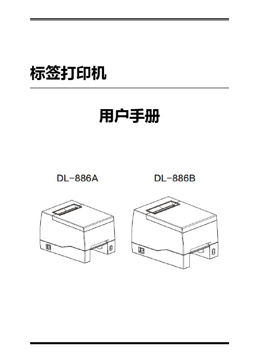
得力DL-886A 2寸标签打印机用户手册 说明书
标签打印机用户手册目录手册信息 (1)安全须知 (2)第1章产品简介 (5)1.1开箱清单 (5)1.2外观及组件 (6)1.3产品尺寸 (7)第2章产品规格 (9)第3章安装和使用 (11)3.1安装介质 (11)3.2电源连接 (14)3.3接口连接 (15)3.4操作面板 (16)3.5基本功能使用 (18)3.5.1开机/关机 (18)3.5.2走纸 (18)3.5.3打印测试 (19)3.5.4标签学习 (20)第4章接口 (21)第5章清洁打印机 (22)5.1清洁打印头 (22)5.2清洁传感器、胶辊和纸张路径 (22)附录1:电子信息产品污染控制的说明 (23)手册信息本用户手册包含产品使用、安装等基本信息。
以下手册对各种技术问题和领域有更为详细的介绍。
1.Windows驱动程序手册此手册提供了Windows驱动程序安装使用说明。
2.打印机实用工具手册此手册提供了本产品功能选择软件的使用、操作条件的修改等方面的信息。
安全须知在操作使用打印机之前,请仔细阅读下面的注意事项,以免发生人身伤害或设备损坏。
1.安全警告标志——警告:必须遵守,以免伤害人体,损坏设备。
——注意:给出了打印机操作的重要信息及提示。
2.安全注意事项警告:违反以下事项可能会导致严重的伤亡事故。
1)不要同时将几个插头插入一个多孔电源插座中。
•这会导致过热和火灾。
•如果插头潮湿或者肮脏,请在使用前烘干或者擦拭干净。
•如果插头与电源插座不配套,请不要插上电源。
•只能使用标准化的多孔电源插座。
2)您只能使用本包装中供应的适配器。
•使用其它适配器十分危险。
3)不要通过拉扯连接线的方式拔插头。
•这可能损坏连接线,造成火灾或者打印机故障。
4)不要在手潮湿的时候,插或者拔电源插头。
•这可能导致触电。
5)不要用力弯曲连接线,或者将其置于重物之下。
•连接线损坏后,可能造成火灾。
注意:违反以下事项可能造成轻伤或损坏设备。
1)如果发现打印机不明原因地冒烟、发出气味或者噪音,请拔下插头,再采取急救措施。
C2G 无线视频设备操作指南说明书
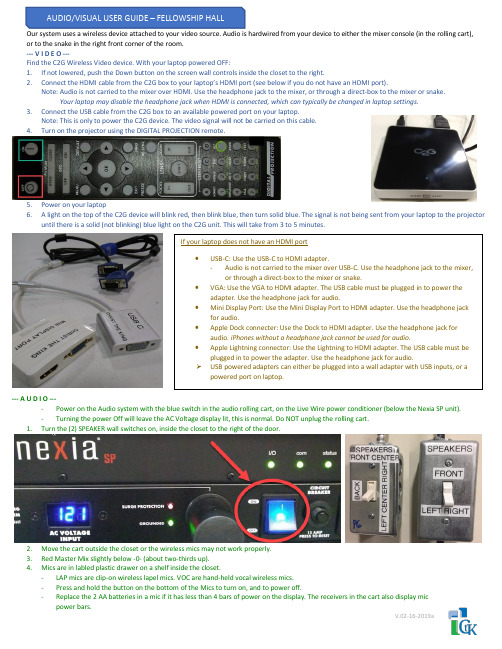
Our system uses a wireless device attached to your video source. Audio is hardwired from your device to either the mixer console (in the rolling cart), or to the snake in the right front corner of the room.--- V I D E O ---Find the C2G Wireless Video device. With your laptop powered OFF:1.If not lowered, push the Down button on the screen wall controls inside the closet to the right.2.Connect the HDMI cable from the C2G box to your laptop’s HDMI port (see below if you do not have an HDMI port).Note: Audio is not carried to the mixer over HDMI. Use the headphone jack to the mixer, or through a direct-box to the mixer or snake.Your laptop may disable the headphone jack when HDMI is connected, which can typically be changed in laptop settings.3.Connect the USB cable from the C2G box to an available powered port on your laptop.Note: This is only to power the C2G device. The video signal will not be carried on this cable.4.Turn on the projector using the DIGITAL PROJECTION remote.5.Power on your laptop6. A light on the top of the C2G device will blink red, then blink blue, then turn solid blue. The signal is not being sent from your laptop to the projectoruntil there is a solid (not blinking) blue light on the C2G unit. This will take from 3 to 5 minutes.--- A U D I O ----Power on the Audio system with the blue switch in the audio rolling cart, on the Live Wire power conditioner (below the Nexia SP unit).-Turning the power Off will leave the AC Voltage display lit, this is normal. Do NOT unplug the rolling cart.1.Turn the (2) SPEAKER wall switches on, inside the closet to the right of the door.2.Move the cart outside the closet or the wireless mics may not work properly.3.Red Master Mix slightly below -0- (about two-thirds up).4.Mics are in labled plastic drawer on a shelf inside the closet.-LAP mics are clip-on wireless lapel mics. VOC are hand-held vocal wireless mics.-Press and hold the button on the bottom of the Mics to turn on, and to power off.-Replace the 2 AA batteries in a mic if it has less than 4 bars of power on the display. The receivers in the cart also display mic power bars.V.02-16-2019a。
林克尔尼克电子产品说明书

| 1CODE 50019, 50020, 50021, 50022ASSEMBLY M a c h i n e A s s e m b l yM a c h i n e a s s e m b l y (r e a r s i d e )PAGE NAMECODE NO.: K NO.: FIGURE NO.:A B 50019 K14013-1 POWERTEC 280C PRO 1 1 50020 K14014-1 POWERTEC 350C PRO 2 1 50021 K14015-1A POWERTEC 420C PRO 3 2 50022 K14015-1W POWERTEC 420C PRO W 4 3FIGURE A: Machine assemblyItem Descriptionpart number QTY 1 2 3 4 1 MAIN TRANSFORMER T1 B-4247-486-2R 1 X - - - 2 MAIN TRANSFORMER T1 B-4247-484-2R 1 - X - - 3 MAIN TRANSFORMER T1 B-4247-485-2R 1 - - X X 4CHOKE L1C-4244-383-2R1X-- -5 CHOKE L1 C-4244-383-4R 1 - X X X6 RECTIFIER SET V1 1156-112-069R 1 X - - -7 RECTIFIER SET V1 1156-112-070R 1 - X - -8 RECTIFIER SET V1 1156-112-071R 1 - - X X9 FAN M1 1111-311-081R 1 X X - -10 FAN M1 0874-111-002R 1 - - X X11 AUXILIARY TRANSFORMER T2 C-4244-384-1R 1 X X X X12 CONTROL P.C BOARD G4560 C-3731-399-2R 1 X X X X13 CONTROL P.C BOARD US-67 0918-432-068R 1 X X X X14 CONTROL P.C BOARD PD-5 0918-432-073R 1 X X X X15 RECTIFIER SET V2 1156-112-044R 1 X X X X16 CONTACTOR K1 1115-212-177R 1 X - - -17 CONTACTOR K1 1115-212-178R 1 - X - -18 CONTACTOR K1 1115-212-179R 1 - - X X19 GAS VALVE K2 0972-423-012R 1 X X X X20 CAPACITORS C1,C2,C3 1158-121-010R 3 X X X X21 CAPACITOR C4 1158-121-045R 1 X X - -22 CAPACITOR C4 1158-121-001R 1 - - X X23 VOLTAGE SWITCH S2 1115-260-166R 1 X - - -24 VOLTAGE SWITCH S2 1115-260-073R 1 - X X X25 VOLTAGE SWITCH S1 1115-260-167R 1 X - - -26 VOLTAGE SWITCH S1 1115-260-074R 1 - X - -27 MAIN SWITCH S3 1115-270-019R 1 X X X X28 SWITCH S7 1158-650-021R 1 X X X X29 SWITCH S6 1158-650-022R 1 X X X X30 LAMP H1 0917-421-024R 1 X X X X31 SWITCH S4,S5 1115-299-052R 2 X X X X32 POTENTIOMETERS R11,R12 1158-113-304R 2 X X X X33 KNOB 9ET10491R 1 X X X X34 KNOB 9ET13639-3R 4 X X X X35 FEEDING UNIT (complete) C-6713-007-1R 1 X X X X36 EURO SOCKET (outlet guide) C-2985-006-1R 1 X X X X37 SLEEVE 0744-000-192R 1 X X X X38 SOCKET X2,X3 C-2986-001-2R 2 X X X X39 SHUNT B1 0941-712-026R 1 X X X X40 FERRITE TUBE 1158-290-036R 1 X X X X41 FUSE F1 1158-660-006R 1 X X X X42 TURNING WHEEL 1029-660-127R 2 X X X X43 WHEEL 1029-660-250R 2 X X X X44 HINGE 0654-610-004R 5 X X X X45 EDGE SHIELD 1362-212-010R 1 X X X X46 LEFT HOLDER 1362-212-002R 1 X X X X47 RIGHT HOLDER 1362-212-003R 1 X X X X48 EURO SOCKET (insulator) 1362-212-009R 1 X X X X49 CAP 1362-212-004R 2 X X X X50 LEFT SIDE HANDLE ASSEMBLY 1362-212-006R 1 X X X X51 RIGHT SIDE HANDLE ASSEMBLY 1362-212-007R 1 X X X X52 SMALL FLAP 1362-212-001R 1 X X X X53 GAS HOSE -2m D-5578-174-1R 1 X X X X54 GROUND CABLE with WORK CLAMP -3m K14011-1 1 X - - -55 GROUND CABLE with WORK CLAMP -3m K14018-1 1 - X - -56 GROUND CABLE with WORK CLAMP -3m K14019-1 1 - - X X57 QUICK CONNECT COUPLING (ONLYWATER)0744-000-151R 4 - - - X58 FRONT PANEL C-3721-828-1/08R 1 - X X X59 FRONT PANEL C-3721-828-2/08R 1 X - - -60 LEFT SIDE PANEL WITH LABELS C-3721-836-1R 1 X - - -61 LEFT SIDE PANEL WITH LABELS C-3721-836-2R 1 - X - -61 LEFT SIDE PANEL WITH LABELS C-3721-836-3R 1 - - X -62 LEFT SIDE PANEL WITH LABELS C-3721-836-4R 1 - - - X63 RIGHT SIDE PANEL WITH LABEL D-3721-392-4R 1 X - - -64 RIGHT SIDE PANEL WITH LABEL D-3721-392-5R 1 - X - -65 RIGHT SIDE PANEL WITH LABEL D-3721-392-6R 1 - - X X66 LEFT SIDE PANEL D-3721-401-1/33R 1 X X X X67 RIGHT SIDE PANEL C-3721-814-2/33R 1 X X X X68 REAR PANEL C-3721-827-1/08R 1 X X X X69 TOP PANEL D-3773-044-2R 1 X X X X70 FRONT LABEL 2719-107-086R 1 X - - -71 FRONT LABEL 2719-107-087R - X X XFIGURE B: Machine assembly (rear side)Item Description part number QTY 1 2 31 HANDLE 0562-230-005R 1 X X X2 GAS INLET SOCKET D-1891-135-1R 1 X X X3 MAINS CORD whitout PLUG -5m(4x4mm²) D-5578-171-2R 1 X - -3 MAINS CORD whitout PLUG -5m(4x6mm²) D-5578-171-3R 1 - X X4 CIRCUIT BREAKER Q1 (ONLY WATER) 1115-299-027R 1 - - X5 SOCKET X16 (ONLY WATER) 1131-222-004R 1 - - X6 WATER COOLER (ONLY WATER) K10329 1 - - X7 COOLER BRACKET (ONLY WATER) D-2632-641-1/33R 1 - - X。
GM8806C2包装机电子秤说明书(doc 46页)

GM8806C2单秤说明书目录1.概述- 1 -1.1 功能及特点- 1 -1.2 前面板说明- 1 -1.3后面板说明- 3 -1.4技术规格- 4 -- 4 -- 4 -- 4 -2.安装- 5 -2.1一般原则- 5 -2.2传感器的连接- 5 -2.3 开关量接口的连接- 6 -2.4 电源连接- 7 -2.5串行口的连接- 7 -- 7 -- 8 -- 9 -3.标定- 17 -3.1标定方法- 17 -3.1.1 进入功能设置- 17 -3.1.2 单位设置- 17 -- 18 -- 18 -- 18 -- 18 -- 19 -- 19 -- 20 -- 21 -3.2标定参数表- 21 -4.工作参数设置- 22 -4.1 工作参数的设置方法- 22 -4.2 工作参数说明- 22 -5.配方的查询与修改- 25 -5.1 查询与设置方法- 25 -- 25 -- 25 -5.2配方参数内容- 25 -6.操作- 30 -6.1仪表的工作状态- 30 -6.2去皮与置皮- 30 -6.3手动卸料- 31 -6.4手动清零- 31 -6.5批次数设定- 31 -6.6时间和日期的查看与设定- 31 -6.7累计内容的查看与清除- 32 -6.8累计内容的打印- 32 -6.9料位及供料控制- 33 -6.10开关量测试- 33 -6.11开关量定义- 34 -6.12快速设置参数值- 35 -6.12.1快速设置目标值- 35 -6.12.2快速设置配方参数F1 - 35 -6.13参数备份及恢复功能- 35 -6.14拍袋说明- 36 -7.自动包装过程- 37 -7.1有计量斗包装模式- 37 -7.2无计量斗包装模式- 39 -8.错误及报警信息- 43 -9.仪表尺寸- 44 -9.1仪表外形尺寸- 44 -9.2开孔尺寸- 44 -。
高冠系统说明书

VVVF
广州市西奥电梯有限公司
102
JTK
轿顶急停
103 (无机房用)
KSK1
卡梯开关
103A KSK2
卡梯开关
103B
AK
轿厢急停
104
SJK
上极限开关
107
JSK
夹绳器开关
106
XSK
限速器开关
105
QK
安全钳开关
108 XJK
下极限开关
109 PSE
对重缓冲器开关
110
PSF
轿厢缓冲器开关
113
慢下
48 轿厢检修 49 轿顶检修
53
慢上
慢下
50 51
慢上
慢下
P1
上平层感应器
MQK
门区
P2
下平层感应器
SHK 低速上强迫换速开关
SHK1 高速上强迫换速开关
SXW 上限位
XHK 低速下强迫换速开关
XHK1 高速下强迫换速开关
XXW 下限位
YX1
YJ 安全回路检测
MX1
MSJ1
MX2
MSJ2
X16
6RD 3A
+
302
C1
300
EL10
轿顶插座
EN10
底坑插座
2RD 6A L2 3RD 6A L3
Q2
Q1
AC1
输入
AC2 电源 AC220V 应 急 照 明
380V
6RD 7RD 6A
KEG
8RD 3A 24V
0V 202
220VAC
12 3 相序
EL10
BK2 601 9RD 3A
MKS 722C 一体化绝对巴特龙绝压电容漏管说明书

transducers are backed with a full two-year warranty.Key BenefitsSmaller manometer size helps achieve overallsystem size reductionCorrosion resistant — all-metal, all-welded con-struction exposes only Inconel and stainless steel to the mediaDrop in replacement compatible with earlier 722Baratron capacitance manometers722C_11/21©2021 MKS Instruments, Inc.Specifications are subject to change without notice.Ordering Code Example: 722C12TCE2FJCodeConfigurationModel 722C722C722CFull Scale Pressure Range (mmHg)1 2 10 20 30 50 100 250 500 1,0002,000 (must be ordered with a fitting)5,000 (must be ordered with a fitting other than NW16KF) 10,000 (must be ordered with a fitting other than NW16KF) 20,000 (must be ordered with a fitting other than NW16KF) 25,000 (must be ordered with a fitting other than NW16KF)01T 02T 11T 21T 31T 51T 12T RDT 52T 13T 23T 53T 14T 24T RCT12TFittings¼” VCR Female ½” Tube8 VCR femaleMini-CF, rotable NW 16 KF CD BA CE HA GACEInput/Output+13 to +32 VDC/0-10 VDC+13 to +32 VDC/0-5 VDC 232Accuracy 0.5% of Reading F FConnectors9-pin Type “D”15-pin high density Type “D”4-pin bayonet type, Bendix®-compatible 5-pin terminal strip15-pin Type “D” on 6-inch cableA C D J KJSome Baratron ® capacitance manometer products may not be exported or re-exported to many countries without both US and local government export licenses under ECCN 2B230. mksinst ™ is a trademark and Baratron ® is a registered trademark of MKS Instruments, Inc., Andover, MA. All other trademarks cited herein are the property of their respective owners.SpecificationsConfiguration Absolute, single-endedFull Scale Ranges 1 Torr through 25,000 Torr (mmHg) (0.02 psia through 500 psia)Accuracy 0.5% of Reading (including non-linearity, hysteresis, and non-repeatability)Response Time< 20 msecTemperature Coefficients Zero Span • 0.008% of Full Scale/°C (10 Torr through 25,000 Torr); 0.020% of Full Scale (1 and 2 Torr)• 0.04% of Reading/°CAmbient Operating Temperature 0° to 50°C (32° to 122°F), 15° to 40°C (59° to 104°F) (1 and 2 Torr only)Overpressure Limit 45 psia or 2x Full Scale, whichever is greater Burst Pressure10x Full Scale or 100 psi, whichever is greater Materials Exposed to GasesInconel ® (Optional Fittings: 316SS)Power InputOutput • +13 VDC to +32 VDC @ 10 mA max. (For drop-in replacements of 122A and B which have a ±15 VDC input, use Input/Output Ordering Code 2. See below.) 0 to 5 Volt output, +10.8 VDC to +32 VDC @ 10 mA max (regulated if below 13 VDC)• 0 to 10 VDC into > 10K ohms load • 0 to 5 VDC into > 10K ohms loadElectrical Connectors9-pin Type “D”, 15-pin high density Type “D”, 15-pin Type “D” on 4.70’’ (118mm) ±0.5'' (12.7mm) cable, 4-pin bayonet type, Bendix ®-compatible, 5-pin terminal strip Fittings Standard Optional • ½'' tube• ¼'' VCR ® female, 8 VCR female, NW 16 KF 1, mini-CF ComplianceCE 21NW 16 KF fittings cannot be used on units with a pressure range of 10,000 mmHg and higher. For units with a pressure range of 5,000 mmHg, an HPS Overpressure ring must be used.2For CE Compliance, an overall metal braided shielded cable, properly grounded at both ends, is required.。
M2488 卡带磁带机产品指南说明书

C144-E019-03ENM2488 CARTRIDGE TAPE DRIVEPRODUCT GUIDEPlease complete the comment from at the back of this manual and send it by mail or facsimile to the indicated address.The contents of this manual may be revised without prior notice.The contents of this manual shall not be disclosed in any way or reproduced in any media without the express written permission of Fujitsu Limited.All Rights Reserved, Copyright © FUJITSU LIMITED 1996, 1997C144-E019-03ENM2488 USER’S GUIDE PREFACEPREFACEThe M2488 User’s Guide provides the information necessary for the user to operate the M2488 Car-tridge Tape Drive.Chapter 1 IntroductionThis chapter provides an overview of the M2488 Cartridge Tape Drive and its optional equipment.Chapter 2 Installation InstructionsThis chapter provides procedures for the preparation and assembly of the M2488 Cartridge TapeDrive.Chapter 3 Controls and IndicatorsThis chapter describes the controls, indicators and connectors for the M2488 Cartridge Tape Driveand its optional equipment.Chapter 4 ConfigurationThis chapter describes the configuration menus of the M2488 Cartridge Tape Drive.Chapter 5 Operating InstructionsThis chapter provides procedures for operating the M2488 Cartridge Tape Drive and its optionalequipment.Chapter 6 Maintenance and ServicingThis chapter describes the user maintenance and servicing of the M2488 Cartridge Tape Drive.Chapter 7 Parts ListThis chapter describes the M2488 models and optional equipment available.The ANSI X3.131-199x SCSI specification may be purchased from:American National Standard Institute, Inc.1430 Broadway, New York, N.Y. 10018Tel. (212) 642-4900SCSI-2 unreleased documentation X3B5/87-099 may be obtained from:Global Engineering Documents2805 McGawIrvine, CA 92714CONVENTIONHexadecimal numbers are denoted by an “h” following the number (e.g. 23h) or 0xNN.Binary numbers are denoted by a “b” following the number (e.g. 001b).C144-E019-03EN iM2488 PRODUCT GUIDE TABLE OF CONTENTSTABLE OF CONTENTSCHAPTER TITLE PAGEREVISION RECORD. . . . . . . . . . . . . . . . . . . . . . . . . . . . . . . . . . . . . . . . . . . . . . . . . . . . . . . . iDIRECTORY. . . . . . . . . . . . . . . . . . . . . . . . . . . . . . . . . . . . . . . . . . . . . . . . . . . . . . . . . . . . . . . iiAGENCY STATEMENTS . . . . . . . . . . . . . . . . . . . . . . . . . . . . . . . . . . . . . . . . . . . . . . . . . . . . iiiPREFACE . . . . . . . . . . . . . . . . . . . . . . . . . . . . . . . . . . . . . . . . . . . . . . . . . . . . . . . . . . . . . . . . . ivINFORMATION LOCATOR . . . . . . . . . . . . . . . . . . . . . . . . . . . . . . . . . . . . . . . . . . . . . . . . . viTABLE OF CONTENTS . . . . . . . . . . . . . . . . . . . . . . . . . . . . . . . . . . . . . . . . . . . . . . . . . . . . . ixLIST OF FIGURES. . . . . . . . . . . . . . . . . . . . . . . . . . . . . . . . . . . . . . . . . . . . . . . . . . . . . . . . . . xxiLIST OF TABLES. . . . . . . . . . . . . . . . . . . . . . . . . . . . . . . . . . . . . . . . . . . . . . . . . . . . . . . . . . . xxiii1INSTALLATION INSTRUCTIONS. . . . . . . . . . . . . . . . . . . . . . . . . . . . . . . . . . . . . . . . . . . . 1-1 1-1 INTRODUCTION . . . . . . . . . . . . . . . . . . . . . . . . . . . . . . . . . . . . . . . . . . . . . . . . . . . . 1-11-2 PREPARING THE M2488 AND ITS OPTIONAL EQUIPMENT . . . . . . . . . . . . . . 1-11-3 CONFIGURATIONS. . . . . . . . . . . . . . . . . . . . . . . . . . . . . . . . . . . . . . . . . . . . . . . . . . 1-1 1-3.1 Rack-mount . . . . . . . . . . . . . . . . . . . . . . . . . . . . . . . . . . . . . . . . . . . . . . . . . . . 1-21-3.2 Desktop. . . . . . . . . . . . . . . . . . . . . . . . . . . . . . . . . . . . . . . . . . . . . . . . . . . . . . . 1-3 1-4 UNPACKING INSTRUCTIONS . . . . . . . . . . . . . . . . . . . . . . . . . . . . . . . . . . . . . . . . 1-4 1-4.1 Unpack the M2488 Tape Drive . . . . . . . . . . . . . . . . . . . . . . . . . . . . . . . . . . . . 1-41-4.2 Unpack the Automatic Cartridge Loader. . . . . . . . . . . . . . . . . . . . . . . . . . . . . 1-51-4.3 Unpack the Flush-mounted Automatic Cartridge Loader . . . . . . . . . . . . . . . . 1-6 1-5 EQUIPMENT INSPECTION . . . . . . . . . . . . . . . . . . . . . . . . . . . . . . . . . . . . . . . . . . . 1-7 1-5.1 Inspect the M2488 Tape Drive. . . . . . . . . . . . . . . . . . . . . . . . . . . . . . . . . . . . . 1-71-5.2 Inspect the ACL . . . . . . . . . . . . . . . . . . . . . . . . . . . . . . . . . . . . . . . . . . . . . . . . 1-71-5.3 Inspect the FACL. . . . . . . . . . . . . . . . . . . . . . . . . . . . . . . . . . . . . . . . . . . . . . . 1-7 1-6 ASSEMBLY INSTRUCTIONS. . . . . . . . . . . . . . . . . . . . . . . . . . . . . . . . . . . . . . . . . . 1-8 1-6.1 General Installation and Assembly Instructions. . . . . . . . . . . . . . . . . . . . . . . . 1-91-6.1.1 Air Flow and Service Clearances. . . . . . . . . . . . . . . . . . . . . . . . . . . 1-9 1-6.2 Interface Personality Module Installation . . . . . . . . . . . . . . . . . . . . . . . . . . . . 1-91-6.3 Cable and Power Connections . . . . . . . . . . . . . . . . . . . . . . . . . . . . . . . . . . . . . 1-101-6.4 Desktop Installation Instructions . . . . . . . . . . . . . . . . . . . . . . . . . . . . . . . . . . . 1-111-6.4.1 Tools Required. . . . . . . . . . . . . . . . . . . . . . . . . . . . . . . . . . . . . . . . . 1-111-6.4.2 Tape Drive Only. . . . . . . . . . . . . . . . . . . . . . . . . . . . . . . . . . . . . . . . 1-111-6.4.3 Drive with ACL Attached (5-Cartridge Magazine) . . . . . . . . . . . . . 1-111-6.4.4 Drive with ACL Attached (10-Cartridge Magazine) . . . . . . . . . . . . 1-121-6.4.5 Drive with FACL Attached . . . . . . . . . . . . . . . . . . . . . . . . . . . . . . . 1-15 1-6.5 Rack-Mount Installation. . . . . . . . . . . . . . . . . . . . . . . . . . . . . . . . . . . . . . . . . . 1-191-6.5.1 Tools Required. . . . . . . . . . . . . . . . . . . . . . . . . . . . . . . . . . . . . . . . . 1-191-6.5.2 Adjust the Guide Plate . . . . . . . . . . . . . . . . . . . . . . . . . . . . . . . . . . . 1-191-6.5.2.1 Inner Cover Mounted to Mounting Tray. . . . . . . . . . . . 1-191-6.5.2.2 Inner Cover NOT Mounted to Mounting Tray . . . . . . . 1-191-6.5.3 Screw Plate Mounting . . . . . . . . . . . . . . . . . . . . . . . . . . . . . . . . . . . 1-20C144-E019-03EN iiiTABLE OF CONTENTS M2488 PRODUCT GUIDE TABLE OF CONTENTS - CONTINUEDCHAPTER TITLE PAGE1-6.5.4 Attach Mounting Tray. . . . . . . . . . . . . . . . . . . . . . . . . . . . . . . . . . . .1-201-6.5.5 Adjust the Brackets . . . . . . . . . . . . . . . . . . . . . . . . . . . . . . . . . . . . . .1-221-6.5.6 Install the M2488 or M2488 with Medium Changer on theMounting Tray. . . . . . . . . . . . . . . . . . . . . . . . . . . . . . . . . . . . . . . . . . . . . . . . .1-23 1-6.6 Installation of the Automatic Cartridge Loader. . . . . . . . . . . . . . . . . . . . . . . . .1-261-6.6.1 Prepare the M2488 Tape Drive . . . . . . . . . . . . . . . . . . . . . . . . . . . . .1-271-6.6.2 Prepare the ACL . . . . . . . . . . . . . . . . . . . . . . . . . . . . . . . . . . . . . . . .1-281-6.6.3 Connect the M2488 and the ACL . . . . . . . . . . . . . . . . . . . . . . . . . . .1-29 1-6.7 Installation of the Flush-mount Automatic Cartridge Loader. . . . . . . . . . . . . .1-321-6.7.1 Prepare the M2488 Tape Drive . . . . . . . . . . . . . . . . . . . . . . . . . . . . .1-331-6.7.2 Prepare the FACL . . . . . . . . . . . . . . . . . . . . . . . . . . . . . . . . . . . . . . .1-341-6.7.3 Connect the M2488 and the FACL . . . . . . . . . . . . . . . . . . . . . . . . . .1-35 1-7 PREPARATION FOR USE . . . . . . . . . . . . . . . . . . . . . . . . . . . . . . . . . . . . . . . . . . . . .1-372DESIGN ARCHITECTURE. . . . . . . . . . . . . . . . . . . . . . . . . . . . . . . . . . . . . . . . . . . . . . . . . . .2-1 2-1 INTRODUCTION. . . . . . . . . . . . . . . . . . . . . . . . . . . . . . . . . . . . . . . . . . . . . . . . . . . . .2-12-2 OPERATION OF THE M2488. . . . . . . . . . . . . . . . . . . . . . . . . . . . . . . . . . . . . . . . . . .2-12-3 OPERATION OF THE MAGNETIC TAPE CONTROLLER (MTC). . . . . . . . . . . . .2-2 2-3.1 Data Path . . . . . . . . . . . . . . . . . . . . . . . . . . . . . . . . . . . . . . . . . . . . . . . . . . . . . .2-22-3.2 Data Buffer . . . . . . . . . . . . . . . . . . . . . . . . . . . . . . . . . . . . . . . . . . . . . . . . . . . .2-22-3.3 ERDC Compression Feature . . . . . . . . . . . . . . . . . . . . . . . . . . . . . . . . . . . . . . .2-22-3.4 Microprocessor Control. . . . . . . . . . . . . . . . . . . . . . . . . . . . . . . . . . . . . . . . . . .2-32-3.5 Firmware . . . . . . . . . . . . . . . . . . . . . . . . . . . . . . . . . . . . . . . . . . . . . . . . . . . . . .2-4 2-4 OPERATION OF THE MAGNETIC TAPE UNIT (MTU). . . . . . . . . . . . . . . . . . . . .2-4 2-4.1 Airless Tape Path. . . . . . . . . . . . . . . . . . . . . . . . . . . . . . . . . . . . . . . . . . . . . . . .2-42-4.2 Read and Write Electronics. . . . . . . . . . . . . . . . . . . . . . . . . . . . . . . . . . . . . . . .2-53SCSI MESSAGES. . . . . . . . . . . . . . . . . . . . . . . . . . . . . . . . . . . . . . . . . . . . . . . . . . . . . . . . . . . .3-1 3-1 INTRODUCTION. . . . . . . . . . . . . . . . . . . . . . . . . . . . . . . . . . . . . . . . . . . . . . . . . . . . .3-13-2 M2488 TAPE AND MEDIUM CHANGER SCSI MESSAGES. . . . . . . . . . . . . . . . .3-1 3-2.1 ABORT code 06h . . . . . . . . . . . . . . . . . . . . . . . . . . . . . . . . . . . . . . . . . . . . . . .3-23-2.2 BUS DEVICE RESET code 0Ch . . . . . . . . . . . . . . . . . . . . . . . . . . . . . . . . . . .3-23-2.3 COMMAND COMPLETE code 00h . . . . . . . . . . . . . . . . . . . . . . . . . . . . . . . .3-23-2.4 DISCONNECT code 04h . . . . . . . . . . . . . . . . . . . . . . . . . . . . . . . . . . . . . . . . .3-23-2.5 EXTENDED MESSAGE FORMAT code 01h. . . . . . . . . . . . . . . . . . . . . . . . .3-33-2.5.1 Synchronous Data Transfer Request (SDTR) . . . . . . . . . . . . . . . . . .3-33-2.5.2 Wide Data Transfer Request (WDTR) . . . . . . . . . . . . . . . . . . . . . . .3-5 3-2.6 IDENTIFY code 80h-FFh . . . . . . . . . . . . . . . . . . . . . . . . . . . . . . . . . . . . . . . . .3-73-2.7 IGNORE WIDE RESIDUE code 23h. . . . . . . . . . . . . . . . . . . . . . . . . . . . . . . .3-73-2.8 INITIATOR DETECTED ERROR code 05h . . . . . . . . . . . . . . . . . . . . . . . . . .3-83-2.9 LINKED COMMAND COMPLETE code 0Ah . . . . . . . . . . . . . . . . . . . . . . . .3-8iv C144-E019-03ENM2488 PRODUCT GUIDE TABLE OF CONTENTS TABLE OF CONTENTS - CONTINUEDCHAPTER TITLE PAGE3-2.10 LINKED COMMAND COMPLETE (WITH FLAG) code 0Bh. . . . . . . . . . 3-83-2.11 MESSAGE PARITY ERROR code 09h . . . . . . . . . . . . . . . . . . . . . . . . . . . . 3-83-2.12 MESSAGE REJECT code 07h. . . . . . . . . . . . . . . . . . . . . . . . . . . . . . . . . . . . 3-83-2.13 NO OPERATION code 08h. . . . . . . . . . . . . . . . . . . . . . . . . . . . . . . . . . . . . . 3-93-2.14 RESTORE POINTERS code 03h. . . . . . . . . . . . . . . . . . . . . . . . . . . . . . . . . . 3-93-2.15 SAVE DATA POINTER code 02h . . . . . . . . . . . . . . . . . . . . . . . . . . . . . . . . 3-9 3-3 SCSI BUS STATUS . . . . . . . . . . . . . . . . . . . . . . . . . . . . . . . . . . . . . . . . . . . . . . . . . . 3-10 3-3.1 Good Status . . . . . . . . . . . . . . . . . . . . . . . . . . . . . . . . . . . . . . . . . . . . . . . . . . . 3-103-3.2 Check Condition. . . . . . . . . . . . . . . . . . . . . . . . . . . . . . . . . . . . . . . . . . . . . . . . 3-103-3.3 Busy Status. . . . . . . . . . . . . . . . . . . . . . . . . . . . . . . . . . . . . . . . . . . . . . . . . . . . 3-103-3.4 Intermediate Status. . . . . . . . . . . . . . . . . . . . . . . . . . . . . . . . . . . . . . . . . . . . . . 3-103-3.5 Reservation Conflict Status . . . . . . . . . . . . . . . . . . . . . . . . . . . . . . . . . . . . . . . 3-114TAPE UNIT SCSI COMMANDS . . . . . . . . . . . . . . . . . . . . . . . . . . . . . . . . . . . . . . . . . . . . . . 4-1 4-1 INTRODUCTION . . . . . . . . . . . . . . . . . . . . . . . . . . . . . . . . . . . . . . . . . . . . . . . . . . . . 4-14-2 LOGICAL UNITS AND SCSI IDS. . . . . . . . . . . . . . . . . . . . . . . . . . . . . . . . . . . . . . . 4-1 4-2.1 Target ID . . . . . . . . . . . . . . . . . . . . . . . . . . . . . . . . . . . . . . . . . . . . . . . . . . . . . 4-14-2.2 Initiator ID . . . . . . . . . . . . . . . . . . . . . . . . . . . . . . . . . . . . . . . . . . . . . . . . . . . . 4-14-2.3 Tape LUN 0 . . . . . . . . . . . . . . . . . . . . . . . . . . . . . . . . . . . . . . . . . . . . . . . . . . . 4-14-2.4 Media Changer LUN 4. . . . . . . . . . . . . . . . . . . . . . . . . . . . . . . . . . . . . . . . . . . 4-14-2.5 LUN . . . . . . . . . . . . . . . . . . . . . . . . . . . . . . . . . . . . . . . . . . . . . . . . . . . . . . . . . 4-1 4-3 M2488 TAPE SCSI COMMANDS. . . . . . . . . . . . . . . . . . . . . . . . . . . . . . . . . . . . . . . 4-2 4-3.1 Command Description Block Format. . . . . . . . . . . . . . . . . . . . . . . . . . . . . . . . 4-44-3.2 CHANGE DEFINITION command 40h . . . . . . . . . . . . . . . . . . . . . . . . . . . . . 4-54-3.2.1 CHANGE DEFINITION CDB Description. . . . . . . . . . . . . . . . . . . 4-54-3.2.2 CHANGE DEFINITION Changes. . . . . . . . . . . . . . . . . . . . . . . . . . 4-64-3.2.3 CHANGE DEFINITION CHECK CONDITION Status. . . . . . . . . 4-74-3.2.4 CHANGE DEFINITION Sense Keys . . . . . . . . . . . . . . . . . . . . . . . 4-7 4-3.3 DISPLAY command CFh (11h). . . . . . . . . . . . . . . . . . . . . . . . . . . . . . . . . . . . 4-84-3.3.1 DISPLAY CDB Description (11h). . . . . . . . . . . . . . . . . . . . . . . . . . 4-84-3.3.2 Display Data (11h). . . . . . . . . . . . . . . . . . . . . . . . . . . . . . . . . . . . . . 4-94-3.3.3 DISPLAY Sense Keys (11h) . . . . . . . . . . . . . . . . . . . . . . . . . . . . . . 4-11 4-3.4 DISPLAY command CFh (10h). . . . . . . . . . . . . . . . . . . . . . . . . . . . . . . . . . . . 4-124-3.4.1 DISPLAY CDB Description (10h). . . . . . . . . . . . . . . . . . . . . . . . . . 4-124-3.4.2 Display Data (10h). . . . . . . . . . . . . . . . . . . . . . . . . . . . . . . . . . . . . . 4-134-3.4.3 DISPLAY Sense Keys (10h) . . . . . . . . . . . . . . . . . . . . . . . . . . . . . . 4-14 4-3.5 ERASE command 19h . . . . . . . . . . . . . . . . . . . . . . . . . . . . . . . . . . . . . . . . . . . 4-154-3.5.1 ERASE CDB Description. . . . . . . . . . . . . . . . . . . . . . . . . . . . . . . . . 4-154-3.5.2 ERASE Sense Keys . . . . . . . . . . . . . . . . . . . . . . . . . . . . . . . . . . . . . 4-16 4-3.6 INQUIRY command 12h. . . . . . . . . . . . . . . . . . . . . . . . . . . . . . . . . . . . . . . . . 4-184-3.6.1 INQUIRY CDB Description . . . . . . . . . . . . . . . . . . . . . . . . . . . . . . 4-184-3.6.2 INQUIRY CHECK CONDITION Status. . . . . . . . . . . . . . . . . . . . . 4-19C144-E019-03EN vTABLE OF CONTENTS M2488 PRODUCT GUIDE TABLE OF CONTENTS - CONTINUEDCHAPTER TITLE PAGE4-3.6.3 Inquiry Data. . . . . . . . . . . . . . . . . . . . . . . . . . . . . . . . . . . . . . . . . . . .4-194-3.6.4 INQUIRY Sense Keys. . . . . . . . . . . . . . . . . . . . . . . . . . . . . . . . . . . .4-24 4-3.7 LOAD UNLOAD command 1Bh . . . . . . . . . . . . . . . . . . . . . . . . . . . . . . . . . . .4-254-3.7.1 LOAD UNLOAD CDB Description. . . . . . . . . . . . . . . . . . . . . . . . .4-254-3.7.2 LOAD UNLOAD CHECK CONDITION Status . . . . . . . . . . . . . . .4-264-3.7.3 LOAD UNLOAD Sense Keys. . . . . . . . . . . . . . . . . . . . . . . . . . . . . .4-27 4-3.8 LOCATE command 2Bh. . . . . . . . . . . . . . . . . . . . . . . . . . . . . . . . . . . . . . . . . .4-284-3.8.1 LOCATE CDB Description. . . . . . . . . . . . . . . . . . . . . . . . . . . . . . . .4-284-3.8.2 LOCATE CHECK CONDITION Status. . . . . . . . . . . . . . . . . . . . . .4-314-3.8.3 LOCATE Sense Keys . . . . . . . . . . . . . . . . . . . . . . . . . . . . . . . . . . . .4-31 4-3.9 LOG SELECT command 4Ch. . . . . . . . . . . . . . . . . . . . . . . . . . . . . . . . . . . . . .4-324-3.9.1 LOG SELECT CDB Description. . . . . . . . . . . . . . . . . . . . . . . . . . . .4-324-3.9.2 LOG SELECT CHECK CONDITION Status. . . . . . . . . . . . . . . . . .4-32 4-3.10 LOG SENSE command 4Dh. . . . . . . . . . . . . . . . . . . . . . . . . . . . . . . . . . . . . .4-334-3.10.1 LOG SENSE CDB Description. . . . . . . . . . . . . . . . . . . . . . . . . . . .4-334-3.10.2 LOG SENSE Operation. . . . . . . . . . . . . . . . . . . . . . . . . . . . . . . . . .4-344-3.10.3 LOG SENSE Parameters. . . . . . . . . . . . . . . . . . . . . . . . . . . . . . . . .4-354-3.10.3.1 Log Sense Pages. . . . . . . . . . . . . . . . . . . . . . . . . . . . . .4-374-3.10.4 LOG SENSE Sense Keys . . . . . . . . . . . . . . . . . . . . . . . . . . . . . . . .4-48 4-3.11 LOOP WRITE TO READ command C1h. . . . . . . . . . . . . . . . . . . . . . . . . . . .4-494-3.11.1 LOOP WRITE TO READ CDB Description . . . . . . . . . . . . . . . . .4-494-3.11.2 LOOP WRITE TO READ CHECK CONDITION Status . . . . . . .4-504-3.11.3 LOOP WRITE TO READ Sense Keys. . . . . . . . . . . . . . . . . . . . . .4-50 4-3.12 MODE SELECT command 15h . . . . . . . . . . . . . . . . . . . . . . . . . . . . . . . . . . .4-514-3.12.1 MODE SELECT CDB Description. . . . . . . . . . . . . . . . . . . . . . . . .4-514-3.12.2 Mode Select Data. . . . . . . . . . . . . . . . . . . . . . . . . . . . . . . . . . . . . . .4-524-3.12.3 MODE SELECT Sense Keys . . . . . . . . . . . . . . . . . . . . . . . . . . . . .4-55 4-3.13 MODE SENSE command 1Ah . . . . . . . . . . . . . . . . . . . . . . . . . . . . . . . . . . . .4-564-3.13.1 MODE SENSE CDB Description. . . . . . . . . . . . . . . . . . . . . . . . . .4-564-3.13.2 Mode Sense Data. . . . . . . . . . . . . . . . . . . . . . . . . . . . . . . . . . . . . . .4-574-3.13.3 Mode Settings . . . . . . . . . . . . . . . . . . . . . . . . . . . . . . . . . . . . . . . . .4-604-3.13.4 Initiator Setup . . . . . . . . . . . . . . . . . . . . . . . . . . . . . . . . . . . . . . . . .4-604-3.13.5 MODE SENSE Sense Keys. . . . . . . . . . . . . . . . . . . . . . . . . . . . . . .4-62 4-3.14 READ command 08h. . . . . . . . . . . . . . . . . . . . . . . . . . . . . . . . . . . . . . . . . . . .4-634-3.14.1 READ CDB Description . . . . . . . . . . . . . . . . . . . . . . . . . . . . . . . . .4-634-3.14.2 READ CHECK CONDITION Status . . . . . . . . . . . . . . . . . . . . . . .4-644-3.14.3 READ Sense Keys. . . . . . . . . . . . . . . . . . . . . . . . . . . . . . . . . . . . . .4-66 4-3.15 READ BLOCK LIMITS command 05h . . . . . . . . . . . . . . . . . . . . . . . . . . . . .4-684-3.15.1 READ BLOCK LIMITS CDB Description. . . . . . . . . . . . . . . . . . .4-684-3.15.2 READ BLOCK LIMITS Sense Keys . . . . . . . . . . . . . . . . . . . . . . .4-69 4-3.16 READ BUFFER command 3Ch . . . . . . . . . . . . . . . . . . . . . . . . . . . . . . . . . . .4-704-3.16.1 READ BUFFER CDB Description. . . . . . . . . . . . . . . . . . . . . . . . .4-70vi C144-E019-03ENM2488 PRODUCT GUIDE TABLE OF CONTENTS TABLE OF CONTENTS - CONTINUEDCHAPTER TITLE PAGE4-3.16.2 READ BUFFER Sense Keys . . . . . . . . . . . . . . . . . . . . . . . . . . . . . 4-74 4-3.17 READ POSITION command 34h . . . . . . . . . . . . . . . . . . . . . . . . . . . . . . . . . 4-754-3.17.1 READ POSITION CDB Description. . . . . . . . . . . . . . . . . . . . . . . 4-754-3.17.2 READ POSITION Return Data . . . . . . . . . . . . . . . . . . . . . . . . . . . 4-764-3.17.3 Description of Block ID Format. . . . . . . . . . . . . . . . . . . . . . . . . . . 4-784-3.17.4 READ POSITION Sense Keys . . . . . . . . . . . . . . . . . . . . . . . . . . . 4-79 4-3.18 READ REVERSE command 0Fh . . . . . . . . . . . . . . . . . . . . . . . . . . . . . . . . . 4-804-3.18.1 READ REVERSE CDB Description . . . . . . . . . . . . . . . . . . . . . . . 4-804-3.18.2 READ REVERSE CHECK CONDITION Status . . . . . . . . . . . . . 4-814-3.18.3 READ REVERSE Sense Keys. . . . . . . . . . . . . . . . . . . . . . . . . . . . 4-82 4-3.19 RECEIVE DIAGNOSTIC RESULTS command 1Ch. . . . . . . . . . . . . . . . . . 4-834-3.19.1 RECEIVE DIAGNOSTIC RESULTS CDB Description. . . . . . . . 4-834-3.19.2 Diagnostic Page Codes (PF=1 in SEND DIAGNOSTICcommand CDB) . . . . . . . . . . . . . . . . . . . . . . . . . . . . . . . . . . . . . . . . . . . . . . . 4-854-3.19.3 Diagnostic Parameter List (PF=0 in SEND DIAGNOSTICcommand CDB) . . . . . . . . . . . . . . . . . . . . . . . . . . . . . . . . . . . . . . . . . . . . . . . 4-874-3.19.4 RECEIVE DIAGNOSTIC RESULTS CHECK CONDITIONStatus. . . . . . . . . . . . . . . . . . . . . . . . . . . . . . . . . . . . . . . . . . . . . . . . . . . . . . . . 4-874-3.19.5 RECEIVE DIAGNOSTIC RESULTS Sense Keys . . . . . . . . . . . . 4-88 4-3.20 RECEIVE DIAGNOSTIC RESULTS (FACTORY MODE) command 1Ch 4-894-3.20.1 RECEIVE DIAGNOSTIC RESULTS (FACTORY MODE)CDB Description. . . . . . . . . . . . . . . . . . . . . . . . . . . . . . . . . . . . . . . . . . . . . . . 4-894-3.20.2 Diagnostic Page Codes (PF=1 in SEND DIAGNOSTICcommand CDB) . . . . . . . . . . . . . . . . . . . . . . . . . . . . . . . . . . . . . . . . . . . . . . . 4-914-3.20.3 Diagnostic Parameter List (PF=0 in SEND DIAGNOSTICcommand CDB) . . . . . . . . . . . . . . . . . . . . . . . . . . . . . . . . . . . . . . . . . . . . . . . 4-964-3.20.4 RECEIVE DIAGNOSTIC RESULTS CHECK CONDITIONStatus. . . . . . . . . . . . . . . . . . . . . . . . . . . . . . . . . . . . . . . . . . . . . . . . . . . . . . . . 4-964-3.20.5 RECEIVE DIAGNOSTIC RESULTS Sense Keys . . . . . . . . . . . . 4-97 4-3.21 RECOVER BUFFERED DATA command 14h . . . . . . . . . . . . . . . . . . . . . . 4-984-3.21.1 RECOVER BUFFERED DATA CDB Description. . . . . . . . . . . . 4-984-3.21.2 RECOVER BUFFERED DATA Operation. . . . . . . . . . . . . . . . . . 4-994-3.21.3 RECOVER BUFFERED DATA CHECK CONDITION Status. . 4-994-3.21.4 RECOVER BUFFERED DATA Sense Keys . . . . . . . . . . . . . . . . 4-100 4-3.22 RELEASE UNIT command 17h . . . . . . . . . . . . . . . . . . . . . . . . . . . . . . . . . . 4-1014-3.22.1 RELEASE UNIT CDB Description. . . . . . . . . . . . . . . . . . . . . . . . 4-1014-3.22.2 RELEASE UNIT Operation. . . . . . . . . . . . . . . . . . . . . . . . . . . . . . 4-1024-3.22.3 RELEASE UNIT Sense Keys . . . . . . . . . . . . . . . . . . . . . . . . . . . . 4-102 4-3.23 REQUEST SENSE command 03h. . . . . . . . . . . . . . . . . . . . . . . . . . . . . . . . . 4-1034-3.23.1 REQUEST SENSE CDB Description . . . . . . . . . . . . . . . . . . . . . . 4-1034-3.23.2 REQUEST SENSE CHECK CONDITION Status . . . . . . . . . . . . 4-1034-3.23.3 REQUEST SENSE Sense Keys. . . . . . . . . . . . . . . . . . . . . . . . . . . 4-104 4-3.24 Report Density Support command 44h . . . . . . . . . . . . . . . . . . . . . . . . . . . . . 4-105C144-E019-03EN viiTABLE OF CONTENTS M2488 PRODUCT GUIDE TABLE OF CONTENTS - CONTINUEDCHAPTER TITLE PAGE4-3.24.1 REPORT DENSITY SUPPORT CDB Description . . . . . . . . . . . .4-1054-3.24.2 REPORT DENSITY SUPPORT Data. . . . . . . . . . . . . . . . . . . . . . .4-1064-3.24.3 REPORT DENSITY SUPPORT Sense Keys . . . . . . . . . . . . . . . . .4-111 4-3.25 RESERVE UNIT command 16h. . . . . . . . . . . . . . . . . . . . . . . . . . . . . . . . . . .4-1124-3.25.1 RESERVE UNIT CDB Description . . . . . . . . . . . . . . . . . . . . . . . .4-1124-3.25.2 RESERVE UNIT Operation . . . . . . . . . . . . . . . . . . . . . . . . . . . . . .4-1134-3.25.3 RESERVE UNIT Sense Keys. . . . . . . . . . . . . . . . . . . . . . . . . . . . .4-114 4-3.26 REWIND command 01h . . . . . . . . . . . . . . . . . . . . . . . . . . . . . . . . . . . . . . . . .4-1154-3.26.1 REWIND CDB Description . . . . . . . . . . . . . . . . . . . . . . . . . . . . . .4-1154-3.26.2 REWIND CHECK CONDITION Status. . . . . . . . . . . . . . . . . . . . .4-1154-3.26.3 REWIND Sense Keys . . . . . . . . . . . . . . . . . . . . . . . . . . . . . . . . . . .4-116 4-3.27 SEND DIAGNOSTIC command 1Dh. . . . . . . . . . . . . . . . . . . . . . . . . . . . . . .4-1174-3.27.1 SEND DIAGNOSTIC CDB Description. . . . . . . . . . . . . . . . . . . . .4-1174-3.27.2 SEND DIAGNOSTIC CHECK CONDITION Status. . . . . . . . . . .4-1194-3.27.3 Diagnostic Pages (PF=1). . . . . . . . . . . . . . . . . . . . . . . . . . . . . . . . .4-1194-3.27.4 Diagnostic Parameter List (PF=0). . . . . . . . . . . . . . . . . . . . . . . . . .4-1224-3.27.5 SEND DIAGNOSTIC Sense Keys . . . . . . . . . . . . . . . . . . . . . . . . .4-123 4-3.28 SEND DIAGNOSTIC (FACTORY MODE) command 1Dh . . . . . . . . . . . . .4-1244-3.28.1 SEND DIAGNOSTIC CDB Description. . . . . . . . . . . . . . . . . . . . .4-1244-3.28.2 SEND DIAGNOSTIC (FACTORY MODE) CHECKCONDITION Status. . . . . . . . . . . . . . . . . . . . . . . . . . . . . . . . . . . . . . . . . . . . .4-1264-3.28.3 Diagnostic Pages (PF=1). . . . . . . . . . . . . . . . . . . . . . . . . . . . . . . . .4-1264-3.28.4 Diagnostic Parameter List (PF=0). . . . . . . . . . . . . . . . . . . . . . . . . .4-1324-3.28.5 SEND DIAGNOSTIC Sense Keys . . . . . . . . . . . . . . . . . . . . . . . . .4-134 4-3.29 SPACE command 11h. . . . . . . . . . . . . . . . . . . . . . . . . . . . . . . . . . . . . . . . . . .4-1354-3.29.1 SPACE CDB Description . . . . . . . . . . . . . . . . . . . . . . . . . . . . . . . .4-1354-3.29.2 SPACE CHECK CONDITION Status . . . . . . . . . . . . . . . . . . . . . .4-1364-3.29.3 SPACE Sense Keys. . . . . . . . . . . . . . . . . . . . . . . . . . . . . . . . . . . . .4-137 4-3.30 TEST UNIT READY command 00h. . . . . . . . . . . . . . . . . . . . . . . . . . . . . . . .4-1384-3.30.1 TEST UNIT READY CDB Description . . . . . . . . . . . . . . . . . . . . .4-1384-3.30.2 TEST UNIT READY CHECK CONDITION Status . . . . . . . . . . .4-1384-3.30.3 TEST UNIT READY Sense Keys. . . . . . . . . . . . . . . . . . . . . . . . . .4-139 4-3.31 WRITE command 0Ah . . . . . . . . . . . . . . . . . . . . . . . . . . . . . . . . . . . . . . . . . .4-1404-3.31.1 WRITE CDB Description . . . . . . . . . . . . . . . . . . . . . . . . . . . . . . . .4-1404-3.31.2 WRITE CHECK CONDITION Status . . . . . . . . . . . . . . . . . . . . . .4-1404-3.31.3 WRITE Sense Keys. . . . . . . . . . . . . . . . . . . . . . . . . . . . . . . . . . . . .4-143 4-3.32 WRITE BUFFER command 3Bh . . . . . . . . . . . . . . . . . . . . . . . . . . . . . . . . . .4-1444-3.32.1 WRITE BUFFER CDB Description . . . . . . . . . . . . . . . . . . . . . . . .4-1444-3.32.2 WRITE BUFFER CHECK CONDITION Status . . . . . . . . . . . . . .4-1484-3.32.3 WRITE BUFFER Sense Keys. . . . . . . . . . . . . . . . . . . . . . . . . . . . .4-149 4-3.33 WRITE FILEMARKS command 10h. . . . . . . . . . . . . . . . . . . . . . . . . . . . . . .4-1504-3.33.1 WRITE FILEMARKS CDB Description . . . . . . . . . . . . . . . . . . . .4-150viii C144-E019-03ENM2488 PRODUCT GUIDE TABLE OF CONTENTS TABLE OF CONTENTS - CONTINUEDCHAPTER TITLE PAGE4-3.33.2 WRITE FILEMARKS CHECK CONDITION Status. . . . . . . . . . 4-1514-3.33.3 WRITE FILEMARKS Sense Keys . . . . . . . . . . . . . . . . . . . . . . . . 4-152 4-4 COMMAND DISCONNECTION. . . . . . . . . . . . . . . . . . . . . . . . . . . . . . . . . . . . . . . . 4-1534-5 SCSI RESET . . . . . . . . . . . . . . . . . . . . . . . . . . . . . . . . . . . . . . . . . . . . . . . . . . . . . . . . 4-1535TAPE UNIT PARAMETERS. . . . . . . . . . . . . . . . . . . . . . . . . . . . . . . . . . . . . . . . . . . . . . . . . . 5-1 5-1 INTRODUCTION . . . . . . . . . . . . . . . . . . . . . . . . . . . . . . . . . . . . . . . . . . . . . . . . . . . . 5-15-2 ADDITIONAL COMMAND INFORMATION ON MTU MODE SELECT ANDMODE SENSE COMMANDS. . . . . . . . . . . . . . . . . . . . . . . . . . . . . . . . . . . . . . . . . . . . . . . 5-1 5-2.1 The Parameters Savable Bit (All pages). . . . . . . . . . . . . . . . . . . . . . . . . . . . . . 5-15-2.2 Vendor Unique Parameter . . . . . . . . . . . . . . . . . . . . . . . . . . . . . . . . . . . . . . . . 5-25-2.3 Error Recovery and Reporting Parameters. . . . . . . . . . . . . . . . . . . . . . . . . . . . 5-45-2.4 Disconnect/Reconnect Control Parameters . . . . . . . . . . . . . . . . . . . . . . . . . . . 5-75-2.5 Common Device-Type Control Parameters. . . . . . . . . . . . . . . . . . . . . . . . . . . 5-95-2.6 Device Configuration Parameters. . . . . . . . . . . . . . . . . . . . . . . . . . . . . . . . . . . 5-115-2.7 Density Code 28h. . . . . . . . . . . . . . . . . . . . . . . . . . . . . . . . . . . . . . . . . . . . . . . 5-145-2.7.1 M2488 Operation When Density Code 28h Is Not Configured. . . . 5-155-2.7.2 M2488 Operation When Density Code 28h Is Configured . . . . . . . 5-15 5-3 MTU INQUIRY/CHANGE DEFINITION VITAL PRODUCT DATA PAGES. . . . 5-17 5-3.1 General VPD Page Format. . . . . . . . . . . . . . . . . . . . . . . . . . . . . . . . . . . . . . . . 5-175-3.2 Supported VPD Pages - Page 00h . . . . . . . . . . . . . . . . . . . . . . . . . . . . . . . . . . 5-195-3.3 Unit Serial Number Page - Page 80h . . . . . . . . . . . . . . . . . . . . . . . . . . . . . . . . 5-195-3.4 Implemented Operating Definition Page - Page 81h . . . . . . . . . . . . . . . . . . . . 5-205-3.5 ASCII Implemented Operating Definition Page - Page 82h . . . . . . . . . . . . . . 5-215-3.6 Unit Usage Page - Page C0h . . . . . . . . . . . . . . . . . . . . . . . . . . . . . . . . . . . . . . 5-225-3.7 Configuration Page - Page C1h . . . . . . . . . . . . . . . . . . . . . . . . . . . . . . . . . . . . 5-235-3.8 Product Identification Page - Page C2h . . . . . . . . . . . . . . . . . . . . . . . . . . . . . . 5-246MEDIA CHANGER SCSI COMMANDS. . . . . . . . . . . . . . . . . . . . . . . . . . . . . . . . . . . . . . . . 6-1 6-1 INTRODUCTION . . . . . . . . . . . . . . . . . . . . . . . . . . . . . . . . . . . . . . . . . . . . . . . . . . . . 6-16-2 MEDIA CHANGER COMMANDS . . . . . . . . . . . . . . . . . . . . . . . . . . . . . . . . . . . . . . 6-1 6-2.1 EXCHANGE MEDIUM MC command A6h. . . . . . . . . . . . . . . . . . . . . . . . . . 6-26-2.1.1 EXCHANGE MEDIUM CDB Description . . . . . . . . . . . . . . . . . . . 6-26-2.1.2 Exchange Medium Examples. . . . . . . . . . . . . . . . . . . . . . . . . . . . . . 6-36-2.1.3 EXCHANGE MEDIUM Sense Keys. . . . . . . . . . . . . . . . . . . . . . . . 6-4 6-2.2 MODE SELECT MC command 15h . . . . . . . . . . . . . . . . . . . . . . . . . . . . . . . . 6-66-2.2.1 MODE SELECT CDB Description . . . . . . . . . . . . . . . . . . . . . . . . . 6-66-2.2.2 MODE SELECT CHECK CONDITION Status . . . . . . . . . . . . . . . 6-86-2.2.3 MODE SELECT Data . . . . . . . . . . . . . . . . . . . . . . . . . . . . . . . . . . . 6-86-2.2.4 MODE SELECT MC Sense Keys . . . . . . . . . . . . . . . . . . . . . . . . . . 6-10 6-2.3 MODE SENSE MC command 1Ah. . . . . . . . . . . . . . . . . . . . . . . . . . . . . . . . . 6-11。
诺基亚 C2-02 C2-07 说明书

诺基亚 C2–02/C2–07 用户手册第 1.0 版45按键与组件5插入 SIM 卡和电池6插入存储卡7为电池充电8连接腕带9开机或关机9 GSM 天线1010密码功能10锁定或解锁按键和屏幕 11触摸屏操作11滑动以打开应用软件或启动功能12指示符号12从旧手机中复制联系人或信息13调节通话、歌曲或视频的音量1414拨打电话14呼叫最近拨打过的电话号码14查看未接来电1415储存姓名和电话号码15使用单键拨号1516书写语言16切换输入法16使用拼音输入法输入内容16笔画输入法17词组输入18启动预想英文输入法18使用传统英文输入法输入内容18使用预想输入法输入内容19输入文字的提示19字典192021发送信息21收听语音信息22发送声音信息 2222关于主屏幕22个性化主屏幕22对您的手机铃声进行个性化设置2324更改时间和日期24设置闹钟24增加约会25农历2525连接安全25蓝牙26 USB 数据线2727调频收音机27媒体播放器2929拍摄图片29录制视频29发送图片或视频30 30关于网络浏览器302目录目录3浏览网络30清除浏览历史记录3131关于邮件31发送邮件31阅读和回复邮件3132关于地图32在地图上查看您的当前位置32查找地点33共享您的位置或地点33制定步行路线3334诺基亚 Ovi 服务的提供情况及价格34访问诺基亚 Ovi 服务3434支持34申请提示和建议服务35随时更新您的手机3536节约能源36回收3636有关配件使用的一些注意事项37为什么使用原厂配件?37电池383963请阅读以下简明的规则。
不遵守这些规则可能会导致危险或触犯法律。
有关更详细信息,请阅读完整的用户指南。
在禁止使用手机的区域应关机当禁止使用手机或手机的使用会引起干扰或危险时 (例如,在飞机上,在医院中或医疗设备、燃料、化学制品或爆破地点附近),请关机。
请遵守受限制区域中的所有规定。
首先要注意交通安全请遵守当地的所有相关法律法规。
MFC2000-2型使用说明书V4.2

2.1 面板
本装置面板由液晶显示屏、操作键、指示灯、232通信接口四部分组成,参见图1。
MFC2000-2 微机厂用电源快速切换装置
运行 工作 动作 通信1
就地 备用 闭锁 通信2
U=100.0% f=50.00Hz
U=100.0% U=100.0% U=100.0% f=49.99Hz
df=0.01Hz dq=5.5Deg
4. 运行巡检说明 ............................................................................................................... 14
4.1 光字牌或DCS信号 ................................................................................................ 14 4.2 面板巡检 ................................................................................................................ 15
T E S T
P W R
FACE
图 2 内部插件布置图(正面)
2.2.2 插件功能简介
CPUB 辅 CPU 插件,主要完成液晶显示、键盘操作、通信、打印等功能。
BROTHER MFC-8460N MFC-8860DN 打印机 说明书
i
目录
第一部分
1 概述信息
使用文档 ............................................................................................................... 文档中使用的符号和惯例 ................................................................................ 使用完整的使用说明书 .......................................................................................... 浏览文档 ......................................................................................................... 操作面板概述 ........................................................................................................ 状态指示灯显示 .............................................................................................. 2 2 2 2 5 8
ii
第二部分
5 发送传真
传真
28 28 28 28 29 29 29 30 30 31 31 31 33 33 34 34 35 35 35 36 36 36
大华硬盘录像机说明介绍模板之令狐文艳创作
硬盘录像机基本操作令狐文艳1 开机插上电源线,按下后面板的电源开关,电源指示灯亮,录像机开机,开机后视频输出默认为多画面输出模式,若开机启动时间在录像设定时间内,系统将自动启动定时录像功能,相应通道录像指示灯亮,系统正常工作。
2 关机A. 关机时,按下后面板的电源开关即可关闭电源。
B. 进入【主菜单】→【关闭系统】中选择【关闭机器】。
2.1.断电恢复当录像机处于录像工作状态下,若系统电源被切断或被强行关机,重新来电后,录像机将自动保存断电前的录像,并且自动恢复到断电前的工作状态继续工作。
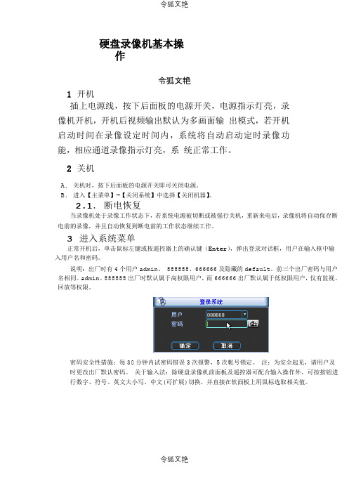
3 进入系统菜单正常开机后,单击鼠标左键或按遥控器上的确认键(Enter),弹出登录对话框,用户在输入框中输入用户名和密码。
说明:出厂时有4 个用户admin、888888、666666 及隐藏的default。
前三个出厂密码与用户名相同。
admin、888888 出厂时默认属于高权限用户,而666666 出厂默认属于低权限用户,仅有监视、回放等权限。
密码安全性措施:每30 分钟内试密码错误3 次报警,5 次帐号锁定。
注:为安全起见,请用户及时更改出厂默认密码。
关于输入法:除硬盘录像机前面板及遥控器可配合输入操作外,可按按钮进行数字、符号、英文大小写、中文(可扩展)切换,并直接在软面板上用鼠标选取相关值。
4 预览设备正常登录后,直接进入预览画面。
在每个预览画面上有叠加的日期、时间、通道名称,屏幕下方有一行表示每个通道的录像及报警状态图标(各种图标的含义见下表)。
通道画面提示:5 录像时间的设置硬盘录像机在第一次启动后的默认录像模式是24 小时连续录像。
进入菜单,可进行定时时间内的连续录像,即对录像在定时的时间段内录像,详细设置在【菜单】>【系统设置】>【录像设置】。
【通道】选择相应的通道号进行通道设置,统一对所有通道设置可选择【全】;【星期】设置普通录像的时间段,在设置的时间范围内才会启动录像;选择相应的星期X 进行设置,每天有六个时间段供设置;统一设置请选择【全】;【预录】可录动作状态发生前1-30 秒录像(时间视码流大小状态);【冗余】1U 机器取消冗余功能,【冗余】使能框为灰显,实际不能操作;【抓图】开启定时抓图。
rmg8862c2程控器说明书

rmg8862c2程控器说明书
RIELLO利雅路RMG88. 62C2黑色程控器说明书
主要用于RIELLO利雅路燃烧器,老型号为RMG88. 62A2。
RIELLO利雅路RMG88. 62C2黑色程控器说明书,产品于RIELLO (利雅路)燃烧器,可用于以下机型,利雅路GS10-20、GAS系歹U、RS系列o
阀门用于防止介质倒流,利用流体自身的动能自行开启,反向流动时自动关闭。
常设于水泵的出口、疏水器出口以及其他不允许流体反向流动的地方。
止回阀分旋启式、升降式和对夹式三种。
对于旋启式止回阀,流体只能从左向右流动时,反向流动时自动关闭。
对于升降式止回阀,流体从左向右流动时;阀芯抬起,形成通路,反向流动时阀芯被压紧到阀座上而被关闭。
对于对夹式止回阀,流体从左向右流动时,阀芯被开启,形成通路,反向流动时阀芯被压紧到阀座上而被关闭,对夹式止回阀可多位安装、体积小、重量轻、结构紧凑。
调节阀
阀门前后压差一定,普通阀门的开度在较大范围内变化时,其流量变化不大,而到某一开度时,流量急剧变化,即调节性能不佳。
调节阀可以按照信号的方向和大小,改变阀芯行程来改变阀门的阻力数,从而到达调节流量目的的阀门。
调节阀分手动调节阀和自动调节阀,而手动或自动调节阀又分许多种类,其调节性能也是不同的。
自动调节阀有自力式流量调节阀和自力式压差调节阀等。
MP8869S评估套件(EVKT-8869S)用户指南说明书

User Guide MP8869S Evaluation Kit (EVKT-8869S)Table of ContentsOverview (3)Section 1. Hardware Specifications (5)1.1Personal Computer Requirements (5)1.2EV8869S-L-00A Specifications (5)1.3EVKT-USBI2C-02 Specifications (5)Section 2. Software Requirements (6)2.1 Software Installation Procedure (6)Section 3. Evaluation Kit Test Set-Up (7)3.1Hardware Set-Up (7)3.2Powering Up the EVB (7)3.3Software Set-Up (7)3.4Troubleshooting Tips (10)Section 4. Ordering Information (11)OverviewIntroductionThe EVKT-8869S is an evaluation kit for the MP8869S. The MP8869S is a highly integrated, high- frequency, synchronous, step-down switcher with an I2C control interface. The MP8869S is optimized to support up to 12A continuous/15A peak output current over an input supply range from 2.85V to 18V with excellent load and line regulation. This kit allows for quick evaluation of the MP8869S. By using the I2C, users can set the current limit, slew rate, work mode, and output voltage. This device also features telemetry, which provides output voltage and output current monitoring via the I2C.Kit ContentsEVKT-8869S kit contents (items below can be ordered separately):#Part Number Item Quantity1 EV8869S-L-00A MP8869SGL evaluation board 12 EVKT-USBI2C-02Includes one USB to I2C communication interface, one USBcable, and one ribbon cable1 Figure 1: EVKT-8869S Evaluation Kit Set-UpRibbon CableFeatures and BenefitsThe MP8869S is highly customizable. Users can program the MP8869S via the MPS I2C GUI.⚠️All changes made in I2C mode will NOT be retained once the EVB is powered down. Adjustable features:I2C•Adjustable output voltage•Slew rate•Selectable OVP, OCP mode•Selectable PFM mode•Selectable PG deglitch time•Selectable frequency•Soft stop•Adjustable current limit•Output current/voltage monitor•System enable (EN bit)•Status indication: OC, OTEW, OT, PG•Kit SpecificationsFeatures SpecificationOperating Input Voltage 2.85V to 18VOutput Voltage (V OUT) 1VContinuous Output Current (I OUT) 12APeak Output Current (I OUT) 15AOperating Systems Supported Windows XP, 7, or laterSystem Requirements Minimum 22.2MB freeGUI Software 3 register controls: VSEL, System1, System2 EVB Size (LxW) 8.5cmx8.5cm1.1 Personal Computer RequirementsThe following must be met to use the EVKT-8869S:•Operating System of Windows XP, 7, or later•Net Framework 4.0•PC with a minimum of one available USB port•At least 22.2MB of free space1.2 EV8869S-L-00A SpecificationsThe EV8869S-L-00A is an evaluation board for the MP8869SGL. For more information, refer to theEV8869S-L-00A datasheet.Feature SpecificationSupply for Evaluation Board 2.85V to 18VOperating Input Voltage 2.85V to 18VOutput Voltage (V OUT) 1VContinuous Output Current (I OUT) 12APeak Output Current (I OUT) 15AEVB Size (LxW) 8.5cmx8.5cmFigure 2: EV8869S-L-00A Evaluation Board1.3 EVKT-USBI2C-02 SpecificationsThe EVKT-USBI2C-02 communication interface connects the EVB, the PC, and its supporting accessories. It provides I2C and PMBus capabilities. Together with the MPS Virtual Bench Pro and GUI tools, it provides a quick and easy way to evaluate the performance of MPS digital products. For more details, refer to the EVKT-USBI2C-02 datasheet.Figure 3: EVKT-USBI2C-02 Communication Interface2.1 Software Installation ProcedureProgramming occurs through the MPS I2C GUI. Follow the instructions below to download and install the software:Note: This software can be downloaded directly from the MPS website.1. Visit the MP88xx I2C GUI page at https:///en/i2c-tool.html.2. Click the “Download” button in the upper right-hand corner.3. Once the download has completed, double-click the .exe file to open the set-up guide (see Figure 4).If a protection window comes up, click “M ore info,” then click “R un anyway.”4. Follow the prompts in the set-up guide.5. Wait for the status screen to verify that installation is complete (see Figure 5).Figure 4: MPS I2C GUI Set-Up GuideFigure 5: MPS I2C GUI Set-Up SuccessSection 3. Evaluation Kit Test Set-Up3.1 Hardware Set-UpThe hardware must be configured properly prior to use. Use the USB cable to connect the EVKT- USBI2C-02 communication interface to the PC, and follow the instructions below to set up the EVB:1. Locate the proper wires to connect the EVB to the EVKT-USBI2C-02 communication interface.2. Connect SCL, SDA, and GND (see Figure 6). If needed, refer to the datasheet for further clarification.Figure 6: EVB to MPS I2C Communication Interface Wire Connection3.2 Powering Up the EVB1. Connect the positive and negative terminals of the load to the VOUT and GND pins, respectively.2. Preset the power supply output between 4.5V and 21V, then turn off the power supply.3. Connect the positive and negative terminals of the power supply output to the VIN and GND pins,respectively.4. Turn the power supply on. The MP8869S will enter the power-on sequence automatically.3.3 Software Set-UpAfter connecting the hardware according to the above steps, follow the steps below to use the GUI software:1. Start the software. It will automatically check the EVB connection.•If the connection is successful, the address will be listed in the “Slave Addre ss” (see Figure 7).Figure 7: Appearance of Address Indicates Successful Connection• If not, a warning will appear at the bottom. There are two warnings users can expect (see Figure8). Each warning means there is an invalid connection.1) “EVB is Disconnected ” means that the evaluation board is not connected.2) “Communication Board is Disconnected ” means that the USB I 2C communication interfaceis not connected.Figure 8: Warning Indicates Unsuccessful ConnectionCommunicationBoard is DisconnectedInvalid Slave AddressEVB is Disconnected2. If the connection is successful, proceed to Step3. Otherwise, check the connections between theEVB, communication interface, and PC. Re-plug the USB into the computer and restart the GUI. 3. Click the “Part Select”button to select the MP8869S (see Figure 7). The default GUI window isfor the MP8861. The Register Control menu will appear on the left side. I2C register values will be read and displayed on the right side after clicking the “Read”button (see Figure 9).Figure 9: Values from I2C Shown in Table4. Find the item you want to change, and select the desired value from the drop-down menu.5. Click the “Read All”button to update values. The changed information of the item will appear onthe right side (see Figure 10).Figure 10: Refer to Datasheet to Translate 0s and 1s⚠️All changes made via the I2C will be restored to default values once the EVB is powered down.3.4Troubleshooting TipsNote: USBI2C-02 and USBI2C-01 drivers are not compatible. USBI2C-02 uses USBXpress and USBI2C-01 uses Cyusb3. USBI2C-02 is the recommended device for MPS PMBus and I2C.EVKT-USBI2C-01If the USBI2C-01 driver is not properly installed, manualinstallation is required. Follow the steps below:1. Open the Device Manager and select “U pdate DriverSoftware” (see Figure 11).2. Click “Browse My Computer for Driver Software,” findthe downloaded driver, and install.EVKT-USBI2C-02If the USBI2C-02 driver is not properly installed, manualinstallation is required. Follow the steps below:Note: Check driver version. Find “USBXpress Device” inthe Device Manager under USB controllers.Right-click and view properties. Check to make sure thedriver version matches the newest version (see Figure 12).1. Install the correct USBXpress “.exe” file.Choose either 32-bit or 64-bit operating system.32-bit: USBXpressInstaller_x86.exe64-bit: USBXpressInstaller_x64.exe2. Connect the EVKT-USBI2C-02 communication interfaceto the PC with the USB cable.•No SupplyThe M P8869S’s input pin has an under-voltage lockout(UVLO) detection circuit. If the input voltage (AVIN) islower than the UVLO rising threshold, the M P8869S’sfunctions are disabled.•Shutdown EventIf the MP8869S detects that the input voltage is lower than the UVLO falling threshold (enter no supply state) or over-temperature protection is triggered (enter power-off state), the MP8869S switches to no supply state or power-off state, regardless of the current state.•Thermal RecoveryIf the MP8869S is in a power-off state due to the die temperature exceeding the thermal protection threshold, the MP8869S enters a power-on sequence once the die’s temperature decreases. •Shutdown SequenceWhen the input voltage is lower than the UVLO falling threshold or the IC is over-temperature, the MP8869S immediately begins the shutdown sequence.Figure 12: Correct Driver VersionFigure 11: Updating the Driver Software11 MP8869S Evaluation Kit User Guide Rev 1.1 10/14/2019 MPS Proprietary Information. Patent Protected. Unauthorized Photocopy and Duplication Prohibited.© 2018 MPS. All Rights Reserved. USER GUIDE – MP8869S EVALUATION KIT (EVKT-8869S) Section 4. Ordering InformationThe components of the evaluation kit can be purchased separately depending on user needs. Part NumberDescription EVKT-8869SComplete evaluation kitContents of EVKT-8869S EV8869S-L-00AMP8869SGL evaluation board EVKT-USBI2C-02 Includes one USB to I 2C communication interface, one USB cable,and one ribbon cable Order directly from .。
- 1、下载文档前请自行甄别文档内容的完整性,平台不提供额外的编辑、内容补充、找答案等附加服务。
- 2、"仅部分预览"的文档,不可在线预览部分如存在完整性等问题,可反馈申请退款(可完整预览的文档不适用该条件!)。
- 3、如文档侵犯您的权益,请联系客服反馈,我们会尽快为您处理(人工客服工作时间:9:00-18:30)。
rmg8862c2说明书
基于带微处理控制器的燃烧器控制器,是监控一段或多段火强制通风燃气燃烧器的简单运行
RMG/RMO系列是根据OEM厂家的要求来制作的,OEM厂家将控制器集成在他们的产品中。
用途:RMG88.62A2、RMG88.62C2/RMG88/M.62C2应用在强制通风燃气燃烧器。
当使用燃气时,由离子棒或者火检探头QRA..来进行检测。
使用燃气:强制通风燃气燃烧器符合EN676标准,RMG88.62C2控制器说明书
燃烧器控制器符合EN298标准
在启动和运行时通过空气压力开关检测空气压力
低电压保护
电器远程复位
数字化信号处理,精确和可重复的顺序控制
连续运行后控制器中断运行
多颜色显示状态及故障信息
RMG88.62C2是RMG88.62A2的升级版本,增加了抗电路*力。
多用于利雅路单段火或双段火燃气燃烧器,如40系列,RS系列等。
凡能使锅炉在操作时,能够安全,自动和经济操作的控制器,都可称为锅炉控制器,也就是说,锅炉控制器可以使用任何种类的控制开关。
锅炉控制器按燃料可以分为电锅炉控制器、燃油锅炉控制器、燃气锅炉控制器;按用途可以分为开水锅炉控制器、热水锅炉控制器、蒸汽锅炉控制器等。