百得燃烧器BAITUR-BT 300 程控器
baltur燃烧器TBG210P17690030中文使用维护手册
• 2014/35/CE (D.B.T.)
• 2006/42/CE (D.M.)
符合以下欧盟标准: • prEN 676:2008(燃气和混合燃料,燃气部分)
• prEN 267:2008(混合燃料,柴油侧)
• EN 60335-1 (2012-01) + EC (2014-01).
1 / 34 0006081523_201711
制造商声明
CE0085: DVGW CERT GmbH, Josef-Wirmer Strasse 1-3-53123 Bonn (D) 兹声明,我们的燃气和混合燃料吹气式燃烧器系列: BPM...; BGN…; BTG…; TBML...; Comist…; GI…; GI…Mist; Minicomist…; Sparkgas...; TBG..; IB..; TBR... (改型产品:... LX,用于低NOx排放;-V用于逆变器,FGR用于烟雾的外部再循环) 符合欧洲指令和法规所规定的最低要求: • 2009/142/CE - (UE) 2016/426 (D.A.G.) (R.A.G.)
危险/注意 此标记表示极端危险。如忽略它们,有可能会严 重影响身体健康或威胁人身安全。
小心/注意事项 此标记表示应采取适当的措施来避免健康和安全 受到影响,以及不让经济受到损失。
重要事项 此标记表示某些不容忽略的重要技术和操作信 息。
存储条件及时长 设备由制造商经过包装进行发货并且使用橡胶垫进行 运输,使用海运以及其他符合运输标准的运输方式。 对于不使用的设备,需要存放在封闭区域并确保标准 空气流通条件(温度在-10°C到+ 40°C)。 存储时期为3年。
调校和维护开始注意事项 • 只允许有资质的专业技术人员在符合现行规范的情
百得BGN-100P燃烧器中文说明书

IEC 730-1 (VDE 0631 T1)
(12) (4)
P1 L1
Mp N
P2 L2 V1,V2 V2
16
筑
DUNGS (GASMULTIBLOC) MB-ZRDLE 415 B01 S22 (1"1/2) / MB-ZR)
MB-ZRDLE B01 ...S.. a) b) c) d) e) ( ( (8) ( ) (7) ) ) (9) (6) DUNGS (10) 5 - 120 mbar
N° 7604-2 Rev. 02/02/96
ul
on g.
co
m
L.P.G.
ww w.
zh
BGN 120 P - 350 P
N° 7605-5 Rev. 17/11/97
筑
龙
网
L.P.G.
5
(
400 mm
) (
8780.tif
400 mm
= 0,04 kg/cm2)
1) 1.5 - 2 2)
3)
MB ..... MB...
DUNGS DUNGS
(400mm
)
BT 8871
网
ww w.
zh
ul
on g.
co
m
筑
龙
DUNGS
6
N° 8871
(
)
BGN 40 P - 250 P
0002933330
1234-
(
)
ww w.
BGN 300 P - 350 P
zh
123450002933340
筑
龙
网
1,2,3,4,5,
on g.
ul
BT300调试指南(中文)
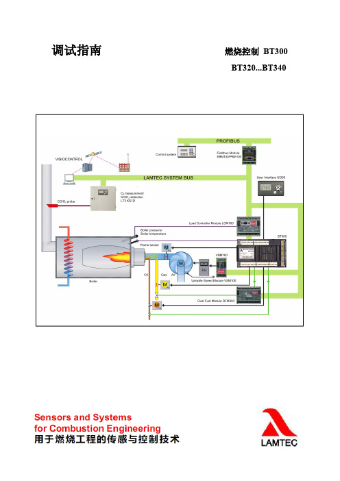
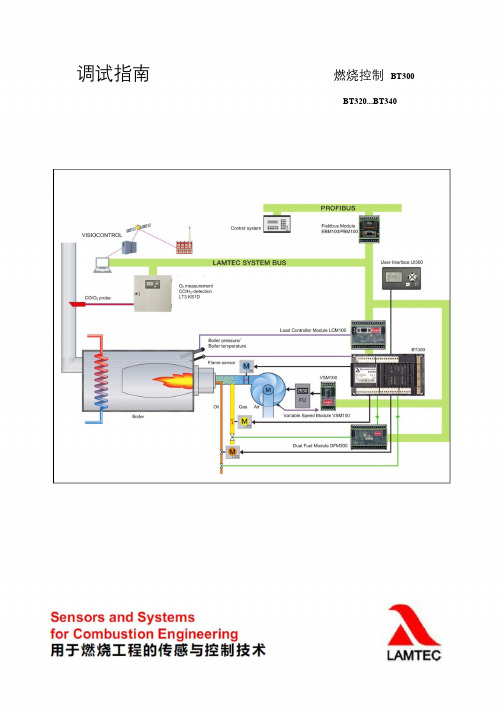
调试指南燃烧控制BT300BT320...BT340一、查线1.控制器接线图X30=UI 300X31=LSB (与LCM100相连,选项)X32、X33、X34接伺服马达,X34为选项2.控制器接线说明●X01、X02分别接阀组的阀1和阀2,X03接阀3(点火支路,选项),X04接点火变压器。
注意!上述4个接线端子,每个端子的1号接线柱为火线输出,3号接线柱为零线。
●X05接燃气检漏开关,在燃烧机运行过程中,该开关变成燃气低压保护开关。
该接线端子3号接线柱为火线,1号接线柱为零线,将开关串到回路即可。
●X06、X07分别为燃烧机安全联锁和锅炉安全联锁,任何一个联锁断开,燃烧机都不能启动运行,或者故障报警(运行中)。
●X08接空气压力开关,监测风机运行。
启动过程或者燃烧机运行中,该回路断开,都会报警。
●X09为负荷输入,直接三点式输入方式(TPS ),该端子3号接线柱为火线,1号柱得电负荷减小,2号柱得电负荷增加。
●X10接启动开关和故障复位,3号柱为火线输出,2号柱得电,启动燃烧机,1号柱得电,则为强制故障复位。
通常故障报警,排除故障后,按红灯键即执行故障复位,如果上述故障复位不能复位,则让X10端子的1号柱得电,执行冷态重阀1,燃气端阀2,燃烧机端阀3/点火阀(选项)点火变压器燃气低压开关燃油低压开关燃烧机安全联锁锅炉安全联锁空气压力开关负荷减小负荷增加故障复位燃烧机启动UV 传感器电离子棒光敏电阻电源输入(230VAC )电源输出报警输出助燃风机燃料油泵燃烧机接地启,还有另外一个可能,即:有故障报警,没有按红灯键复位,而是按保持,此时红灯熄灭,但故障还在,键不能复位,则要使用该故障强制复位。
●X20、X21为火焰检测器(传感器)的接入脚,根据不同的传感器类型,有不同的接线方式,通常:UV管接X21(注意火线在X21的1号柱),X20的4号柱接电离子棒,X20的1号柱和2号柱接光敏电阻。
●X22接线端子可以为系统内其他设备提供230VAC电源,1号柱为火线,3号柱为零线。
百得燃烧器说明书
TBL 105P TBL 105P
DACA
1,050
320
TBL 130P TBL 130P
DACA 1,300
400
两段火式
TBL 160P TBL 160P
DACA
g/kWh kW
r.p.m.
1.1 2,800
< 185 (Classe II EN 267)
燃烧器使用说明
CN
TBL 85P TBL 85P DACA TBL 105P TBL 105P DACA TBL 130P TBL 130P DACA TBL 160P TBL 160P DACA
TBL 210P DACA
0006081285_200801
注意 - 对燃烧器和系统的操作只能由合格的工作人员来执行。 - 启动燃烧器和进行维护保养前,请仔细阅读本说明手册。 - 在对燃烧器的电气系统进行操作前,请先切断供电电源。 - 如果操作及处理不当,可能会引起危险事故。
- 如果身上有水、潮湿或者脚湿的时候不要身体任何部位接触这些设备。 - 不要拉电线。 - 如果不是适宜型号,不要将这些设备暴露在有危险的环境(如雨天或阳光下)。 - 不要让孩子或不专业的人员操作这些设备。 • 客户不得更换供电电缆。如果电缆损坏,停机,让合格的技术人员进行更换。 • 如果暂时不使用设备,则建议切断系统向所有用电设备(泵、燃烧器等)的供电。 燃料供应
0006081285_200801
使用须知
前言 以下的注意事项是为了保证顾客能够安全地使用民用和烧热水用的加热系统设备。这些注意事项的目的是为了 避免这些设备不会因为安装不当或安装错误以及使用不当或使用错误而引起的损坏和安全问题。同时,本使用 说明提供注意事项也希望能够通过一些技术性的但却易懂的语言,使顾客加深对一般性安全问题的了解。不管 是合同内规定的,还是超出合同范围的,如果是由于顾客的不当或错误的安装和使用,或是因为不遵循制造商 的指导而引起的任何问题或事故,制造商均不负责。 一般性注意事项 • 本说明手册对于产品来说是必要的,是产品不可分割的一部分,一定要提供给顾客。请仔细阅读本手册,其
百得燃烧器培训资料_百得燃烧器部分2
若使用含有轻质油的湿气,根据使用情况每年应对燃气阀组 和管路拆下清洗,除去通道内积存的油污,注意只允许使用煤油 或无腐蚀的中性清洗水溶液进行清洗。
4)交流接触器:
每年应对三组触头拆下修理,操作方法:用尖嘴钳直接将接触器 上三组触点拿下,用玻璃砂纸打磨(严重时可换新触头),然后 装复,在装复过程中注意三组触点间隙要一致,否则应给予调
3-5点火、喷油 而无法正常 点火或点火 成功后又自 动熄灭;
1)风门过大,吹熄
火焰;
1)重新调小风
2)火花位置不合适 门;
3)油内水份过高无法 2)校正电极间
正常燃烧;
隙;
4)油压过低,雾化不 3)更换合格燃料;
良,影响燃烧;
4)适当调高油压;
5)喷嘴磨损或雾化角 5)更换喷嘴;
不合适;
6)检修或更换 ;
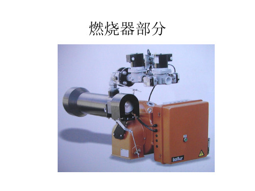
燃烧器部分
1、燃烧器工作方框图
2、燃烧器接线图
3、新燃气TBG系列燃烧器 七孔插头接线图
4、燃烧器主要参数设定及方法
a、调压阀前压力:0~0.4MPa b、调压阀调后的压力:TBG45-85PV:4-6KPa;
TBG120-210P:10Kpa BGN250、300、350:15KPa c、风压开关:0.4~1mbar; d、燃气高压开关:50mbar(特殊例外); e、燃气低压开关:2.5mbar; f、自检漏燃气开关:压力设定值调整到天然气供应管网压力的 一半。 g、伺服电机:Ⅰ(最大):70(60~70); Ⅱ(关闭):0;
2)空气风压开关:
每隔三个月拆下畅通一次,具体操作方法:切断燃烧器电源,打 开空气风压开关有机玻璃罩,拆出三根信号线(记住位置),将 燃烧器风机上盖打开,用专用扳手将风压开关拆下(记住风压管 方向)。
BT300调试指南(中文)
调试指南燃烧控制BT300BT320...BT340一、查线1.控制器接线图燃烧机接地阀1,燃气端燃料油泵阀2,燃烧机端助燃风机阀3/点火阀(选项)报警输出点火变压器电源输入(230VAC)燃气低压开关燃油低压开关电源输出燃烧机安全联锁UV传感器锅炉安全联锁电离子棒空气压力开关光敏电阻负荷减小负荷增加故障复位燃烧机启动X30=UI300X31=LSB(与LCM100相连,选项)X32、X33、X34接伺服马达,X34为选项2.控制器接线说明X01、X02分别接阀组的阀1和阀2,X03接阀3(点火支路,选项),X04接点火变压器。
注意!上述4个接线端子,每个端子的1号接线柱为火线输出,3号接线柱为零线。
X05接燃气检漏开关,在燃烧机运行过程中,该开关变成燃气低压保护开关。
该接线端子3号接线柱为火线,1号接线柱为零线,将开关串到回路即可。
X06、X07分别为燃烧机安全联锁和锅炉安全联锁,任何一个联锁断开,燃烧机都不能启动运行,或者故障报警(运行中)。
X08接空气压力开关,监测风机运行。
启动过程或者燃烧机运行中,该回路断开,都会报警。
X09为负荷输入,直接三点式输入方式(TPS),该端子3号接线柱为火线,1号柱得电负荷减小,2号柱得电负荷增加。
X10接启动开关和故障复位,3号柱为火线输出,2号柱得电,启动燃烧机,1号柱得电,则为强制故障复位。
通常故障报警,排除故障后,按红灯键即执行故障复位,如果上述故障复位不能复位,则让X10端子的1号柱得电,执行冷态重启,还有另外一个可能,即:有故障报警,没有按红灯键复位,而是按保持,此时红灯熄灭,但故障还在,键不能复位,则要使用该故障强制复位。
X20、X21为火焰检测器(传感器)的接入脚,根据不同的传感器类型,有不同的接线方式,通常:UV管接X21(注意火线在X21的1号柱),X20的4号柱接电离子棒,X20的1号柱和2号柱接光敏电阻。
X22接线端子可以为系统内其他设备提供230VAC电源,1号柱为火线,3号柱为零线。
BT300小型的燃烧机控制器
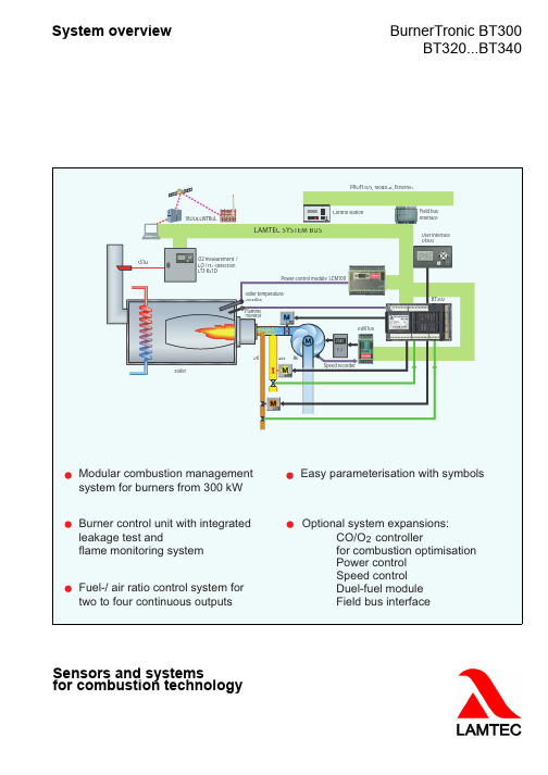
Sensors and systemsfor combustion technologySystem overviewBurnerTronic BT300BT320...BT340AirField bus interface BT300UI300VSM100monitorGas Speed recorderField busPower control module LCM100DESCRIPTION OF FUNCTIONThe BurnerTronic BT300 is a compact burner control for average-sized combustion plants.The BT300 combines the advantages of an electronic fuel-air compound control system with an electronic burner control unit.The following are also integrated:•Leakage test•Flame monitoring system•Power control unit•CO/O2 controller for control and optimisation of an oil or gas-fired forced-draught burnerBurner sequencer and compound control system can be adjusted for a wide range of combustion conditions by setting parameters. The electronic fuel-air ratio control control system controls up to 3 motorised and an optional analogue output for speed control of the combustion air fan.Safety interlock chains, monitors and sensors are wired directly to the BT300.The integrated leakage test can be run before ignition or after shutting down the burner.The defined compound curves can be optimised during operation with the optional CO/O2 controller. This ensures that the burner will always operate at the greatest possible efficiency.The BT300 was designed to be attached to the burner. The short wiring paths also save money. As a result, the BT300 is particularly suitable as standard equipment for monoblock burners.Minimising the wiring and the unified operator interface reduces the possible sources of errors right from the start. Searching for errors is made much easier by intelligent information in the display.An operating and start-up counter is integrated.The BT340 can be set to start with and without pilot burner in accordance with EN 676. Starting without pre-ventilation using gas is available in accordance withEN 676.Operating and fault messages are displayed by icons on the UI300 user interface. This eliminates language barriers when in use abroad. Setting of the compound curves and system-specific configuration are controlled by menus in the UI300 user interfaceOPTIONAL COMPONENTS•LCM100 power control moduleThe LCM100 adds the function of a power control unit to the BurnerTronic. The power control unit offers the option of controlling the temperature (PT100 or PT1000) or the steam pressure (4...20mA pressure sensor).The LCM100 also offers the option of a set-point shift depending on the outside temperature (control by atmospheric condition). A digital 24V input can be used to switch between 2 flexible set-points. The LCM100 also contains the LSB interface and the voltage supply for the following LSB module.•Speed module VSM100With the VSM100 the BurnerTronic can control the speed of fan motors. The BurnerTronic treats the VSM100 as an additional compound channel. This allows the speed profile to be defined as desired over the complete load range. The VSM100 is connected to the BurnerTronic via LSB. The VSM100 outputs the speed set-point to the motor driver as a 0/4...20mA or 0...10V signal (frequency converter or other). The VSM100 records the actual speed and sends it to the BurnerTronic for checking. •Switching module for two fuels DFM300The DFM300 is an expansion module that enables operation of dual-fuel burners in combination with the BurnerTronic BT340.Depending on the selected fuel, the module switches the valve outputs and the ignition transformer output of the BurnerTronic to the valves and ignition transformer for the selected fuel.The DFM300 can also switch over the "burner safety chain" input of the BurnerTronic. This allows the safety chain devices of the currently inactive fuel (e.g. oil pressure monitor during gas operation) to be open.The DFM300 is connected to the BurnerTronic via LSB (LAMTEC SYSTEM BUS). The DFM300 provides a 230VAC input for selection of the current fuel.•Expansion module for LSB - LEM100The LEM100 adds an LSB interface (LSB) to the BurnerTronic. The LEM100 also has a 24VDC output, which can be used to power additional LSB devices. The LEM100 is required if the BurnerTronic is to be connected to the LSB.•CO/O2 optimisation with K1SD and LT3The KS1D combination probe and the LT3 Lambda Transmitter can add a combustion control system to the BurnerTronic. By switching off the O2/CO e value using the LAMTEC SYSTEM BUS the burner can be brought to the optimal point for operation, whilst remaining independent of environmental influences such as temperature, air humidity etc.. This ensures maximum efficiency with minimum emissions.FUNCTION OVERVIEWThe BT300 is available in three designs:•BT320–Two motorised continuous outputs– 1 continuous output 0...10V, 0/4...20mAfor speed control of the combustion air fan viaVMS100 (optional)–Intermittent operation•BT330–One fuel, oil or gas– 1 continuous output 0...10V, 0/4...20mAfor speed control of the combustion air fan viaVMS100 (optional)–Three motorised continuous outputs–approved for continuous operation incombination with a continuously operating flamesensor•BT340–Three motorised continuous outputs–Oil-gas dual-fuel operation via DFM300–One continuous output 0...10V, 0/4...20mA for speed control of the combustion air fan viaVMS100 (optional)–approved for continuous operation incombination with a continuously operating flamesensorDistributed by:Publication no.: DLT1202-11-aEN-001Printed in GermanyLAMTEC Meß- und Regeltechnik für Feuerungen GmbH & Co. K GWiesenstraße 6D-69 190 WalldorfTelephone (+49) 06227 / 6052-0Fax (+49) 06227 / 6052-57Website: mtec.de e-mail: info@lamtec.deLAMTEC Leipzig GmbH & Co. K GSchlesierstraße 55D-04299 LeipzigTelephone (+49) 0341 / 863294-00Fax (+49) 0341 / 863294-10© L A M T E C G m b H & C o .K GBT300 OPERATING MODESGas operating modesOil operating modesGas, modulating with optional speed control of the VL fan Oil, modulating with optional speed control of the VL fanGas, modulating with pilot burner and optionalspeed control of the VL fanOil, 2-stageOil, 3-stage。
百得燃烧器说明书
1.5
2.2
2.2
2,800
2,800
2,800
消耗电功率* 保险
点火变压器 电压 防护等级 火焰检测 噪音** 重量 燃料最大粘度(轻油) 流率
kW1Biblioteka 50A 400 V一般性注意事项 • 必须依照现行的法律和规则,由有资格的技术人员来安装设备。安装不当可能引起对人员、动物或物品的伤
害,这种情况制造商不负责任。 • 建议安装前对燃料供应系统管道进行仔细的内部清洗,清除任何可能影响燃烧器正常工作的残渣。 • 如果是初次使用燃烧器,须由合格技术人员执行以下检查:
a) 检查锅炉房内外燃气的密封性。 b) 将燃料的流量设置为能够保证锅炉所需热量的合适值。 c) 确认供给燃烧器的燃料流量与燃烧器要求的相符。 d) 确认燃料进口压力与燃烧器铭牌上的标示相符。 e) 确认燃料供应管直径足够大以保证供应所需燃料量,并且根据现行规则,管路上要有安全装置。 • 如果将有一段时间不使用设备,断开燃料的供给。 使用燃气的特别注意事项 • 须由合格技术人员根据现行规则执行以下检查: a) 供气管路和阀组符合现行法律和规则。 b) 所有燃气管路的联接均密封良好。 • 如果闻到有燃气: a) 不要使用任何开关、电话或其它任何可能产生火花的设备。 b) 立即打开门窗,让新鲜空气冲走室内燃气。 c) 关闭燃气阀。 d) 向合格的技术人员求助。 • 不要利用燃气管来作为电气设备的接地。 • 设备不使用的时候要将其关闭,并且将燃气阀关闭。 • 如果将有一段时间不使用设备,断开主燃气的供给。 • 如果室内有燃气管路,或者因为出现有毒气体和易爆气体而产生危险情况的环境须保持通风良好。 高效锅炉或类似设备的烟道 应该指出对于高效锅炉或类似设备的燃烧产物(排烟)在烟道内的温度相对较低。这时,传统的烟道(直径和隔热) 可能变得不适合了。因为这类设备对燃烧产物冷却幅度很大,所以排烟温度会很低,可能低于露点。如果烟温
tbg260mc燃烧器技术参数

北京安帝维德技术开发有限公司
技术参数
一、意大利百得燃烧器
制造厂:意大利百得热能技术公司
1、技术参数
1)型号:TBG260MC
1)功率范围:450-2600kw;
2)控制方式:比例调节;
3)电源:三相50Hz 380V AC 电机功率5.5KW;4)燃料:天然气
5)燃气接口尺寸:2" NPTM螺纹;
2、供货范围
1.轻质铝合金风机部件
2.高性能轻质铝合金离心式风机
3.与各种锅炉法兰配对的滑动法兰
4.带有鼓风管和火焰扩散盘的钢制可调节燃烧头
5.三相电机带动风机
6.用伺服电机来控制风门挡板进行空气流量自动调节
7.带有调压器、测压孔和安全阀的燃气阀组. MBDLE420
8.离子探针检测火焰
9.西门子程序程控器
10.一个过滤器,一套调压阀
11.操作说明书
12.比例调节仪:霍尼韦尔DC1020
13.冬斯检漏仪:VPS504
Page 1 of 1。
德国奔克bp300控制系统技术手册以及系统菜单

德国奔克bp300控制系统技术手册以及系统菜单Böhnke + Partner GmbH Werkskonfiguration BP公司出厂菜单设置———————————————————————————————————Steuerungsnr.控制器号: 87576Kunde客户: ZHAOAufzugsnummer电梯号:Sonderangaben特殊说明: ———————————————————————————————————StrgNr.控制器号: 87576AufzNr.电梯号:ProVer.程序版本: 35X-9.04b 20.09.99 14:00CDA-03CLP-03IO-CoP. 输入输出协处理器: V2.9DCPCoP. DCP协处理器: V5.7 ———————————————————————————————————base menu 基本菜单lift data 电梯数据:highest landing 最高层站: 5lowest landing 最低层站: 1SST at floor : no entry 未用type of lift 电梯类型: rope with speed regul. frequency VVVF曳引梯frequency reg. Type变频器类型: F20: ZETADYN 2CF Ziehl Abeggtype of system 系统类型: single lift 单梯shaft copying 井道信息: without switches (encoder at SP7) 无磁开关,编码器接于SP7 type of control 控制类型: full collective select call cancel 全集选,行驶方向召唤消除cod.pos.indica.All 楼层显示: gray code 格雷码All-level offset 所有层站偏移量: 0via A14/A15 经A14/A15 : 7-segmentcode 7段码: 2345start.sp. l fl 启动速度: ssss: 1234functions rope 曳引梯功能:safety switching 安全开关: : stop at level with blocking 平层停车,电梯禁用re-levelling 再平层: with levelcontact 用平层接触开关relevel-switch 再平层开关: make contact 常通relevelling control 再平层控制: cancel releveling at landing 在门区时取消再平层re-levelling 再平层: via main device 经主设备re-levelling 再平层: with c1.153 用接线端153levell.door close 关门时再平层: normal 正常re-levelling 再平层: stop before normal start 在正常启动前停止re-levelling 再平层: brake not delayed 制动不延时PTC thermistor 温控电阻: immediate stop with blocking 立即停车,电梯禁用control term.9 监控线端9 : with blocking 电梯禁用malfunct.cl.35 故障线端35 : immediate stop with blocking立即停车,电梯禁用regulation contr. 调速器监控: immediate stop with blocking立即停车,电梯禁用travel direct. sig. 运行方向指示: when going down 正到达时brake open after 制动开,当: signal c1.31=1 信号接线端31=1brake close after 制动关,当: signal c1.31=0 信号接线端31=0re-levelling 再平层: brake not delayed 制动不延时signal c1.21 信号接线端21 : help-sig. brake 制动器辅助信号signal c1.31 信号接线端31 : make contact 常通signal c1.34 信号接线端34 : break contact 常断speed reduction 减速: from Vs to Vz 从Vs到Vzstandard funct.标准功能:inspection 检修: pushb.fast+door open/close=off 快速键+开关门键=关闭inspection 检修: up to level 直至平层inspection 检修: without close door signal 无关门信号inspection 检修: without lock-sig. c1.48 接线端48无门锁信号insp./emerg.el.op.检修/返回运行: according EN81 按照EN81标准start off zone 门区外启动: distant-triP 远程运行correction signals 校正信号: break contact 常通correction after 校正运行,当: lowest landing 底层floor selector ctr 楼层选择监控: without blocking 电梯不禁用top floor 顶层: without impuls 无脉冲E35-configuration 输入35配置: with relevel switches 再平层开关emergency stop as紧急停车作为: message 警告emergency stop 紧急停车: without call cancel 不删除召唤emergency stop as紧急停车,当: switch 开关emerg.stop-pushb.紧急停车按键: nd.calls aft. open land. Door打开厅门后允许外召open saftey circuit打开安全回路: without call cancel 外召不删除open saftey circuit打开安全回路: without correc.trip 无校正运行singl.fault sign.A13 : variant 1 (B+P) BP型故障信号输出A13direction ind."up"上行方向指示: normal 正常direct.indic."down"下行方向指示: normal 正常direction indicat.运行方向指示: in idle state on空闲时开start load-time开始加载时间: with load-button加载键按下load lift pushb.电梯加载键: car calls cancel lift-load time加载时取消轿内召唤maintenan.interval 保养期内: without blocking电梯不禁用mainten.call-back保养返回召唤: off 关emergency norm紧急情况规范: german 德国标准fireman's ctr.car消防员控制轿厢: door movement normal 门正常开关after firem.ctr.car消防员控制后: return to fire-man's floor 返回消防层floor funk.E28-E32 : off 关楼层功能输入口28-32clearing calls 清除召唤: when arriving 当到达时nd.pushb.off当外召关闭时: car-calls collect. 采集内召nd.pushb.off当外召关闭时: clear car calls at once立即清除内召prior.cabin (64) 轿内优先: off at priority floor 在优先层关priority tota1(154) 总体优先: normal 正常after priority 优先运行后: clear car calls at once立即清除内召after priority 优先运行后: car calls not correctable 内召不可纠正priority:stopover优先:过层: open door 开门priority calls 优先召唤: normal 正常priority:dir.ind.优先:方向指示: normal 正常type SFR SFR控制: without no load 无空载type SFR SFR控制: only 1 car-call 只有一个内召speci.calls R41-48 特别召唤: priority calls 优先召唤priority car calls 轿内优先召唤: via c1.84 经接线端84bei Vorzugsf. Innen轿内优先时: Weiterfahrtanzeige aus 继续运行指示:关Quittungen A72-A79 响应: attendant operat. 司机操作input terminals输入接线端:functions功能:monitor.cl.33监控线端: relay off 继电器关monitor.cl.35监控线端: off关monitor.cl.36监控线端: light aux.circuit备用照明monitor.cl.37监控线端: normal正常monitor.cl.38监控线端: Maschinenraumtemp.机房温度signal c1.83信号线端: addit. Correct 附加校正signal c1.84信号线端: priority car calls collecting采集轿内优先召唤signal c1.141信号线端: off关signal c1.142信号线端: attendant operation only 1car call司机操作,只有一个内召signal c1.143信号线端: off关signal c1.144信号线端: off关signal c1.145信号线端: off关signal on c1.146信号线端off关sign.on c1.221信号线端: off关sign.on c1.222信号线端: off关sign.on c1.225信号线端: off关signal c1.398信号线端: off关logic逻辑:signal c1.33信号线端: break contact常断signal c1.35信号线端: break contact常断rem.off c1.37远程关闭: break contact常断signal c1.38信号线端: break contact常断signal c1.84信号线端: make contact常通signal c1.85信号线端: break contact常断signal c1.86信号线端: make contact常通full load c1.87信号线端: make contact常通overload c1.88过载: make contact常通evacuat.cl.l24疏散信号: make contact常通signal on c1.146信号线端: make contact常通sign.on c1.225信号线端: make contact常通output terminals输出接线端:functions功能:signal c1.43信号线端: close valve关闭阀signal c1.44信号线端: cent.fault indicat 故障信息采集signal c1.45信号线端: occupied 占用signal c1.46信号线端: out of order 电梯失控sign.on c1.47信号线端: zone channel A 门区通道Asig.c1.63 (A64) 信号线端: car chime轿厢钟signal c1.64信号线端: prior.cabin (64) 轿内优先signal c1.66信号线端: close doors 关门signal c1.67信号线端: +24V control power 控制回路供电signal c1.152信号线端: Ladezeit l鋟ft 加载时间signal c1.153信号线端: lift will start 电梯将启动signal c1.155信号线端: service interv. 保养期间signal c1.156信号线端: remote off relay 远程功能关闭继电器sign.on c1.211信号线端: pulse ls-tm125=1 暂停1秒,当接线端=1 sign.on c1.212信号线端: pulse ls-tm125=0 暂停1秒,当接线端=0 logic逻辑:cent.fault indicat故障信息采集: sig. 1->0 信号从1→0doors 门:doors门: A one side only 只有单边门Atype of door A A门类型: autom. doors with endswitch自动门有限位开关sep.sec-l.b.door A 外加光幕: no无function c1.163接线端163功能: normal正常signal c1.191信号端191 : prewarn.close door 关门预警door A with endsw.门限位开关: open and close 开门和关门时endswitch door A门限位开关: break contact常断photo-cell光眼: make contact常通pushbutton open开门按键: make contact常通pushbutton close关门按键: make contact常通load lift pushb.加载按键: make contact常通sensor barrier光幕: make contact常通entrance supervision基层监控: make contact常通doors reversion门反转: only within zone仅在门区内doortable 1门表1 : door A 0000012345ports端口:number of ELP-port ELP端口数: no entry无output-ports输出端口: connect in parallel并行连接ports reserv.端口保留:port: 1 (8 O)端口1(8出) : A03 speed reg.rope lift调速曳引梯,输出口03 port: 2 (8 I)端口2(8入) : --- ***** free *****空port: 3 (8 I)端口3(8入) : E06 control-signals控制信号,输入口06port: 4 (8 O)端口4(8出) : A06 control signals控制信号,输出口06port: 5 (8 O)端口5(8出) : --- ***** free *****空port: 6 (8 O)端口6(8出) : --- ***** free *****空port: 7 (8 O)端口7(8出) : --- ***** free *****空port: 8 (8 O)端口8(8出) : A05 car signals轿厢信号,输出口05port:11(8I/O/C)端口11(8入/出/组合) : --- ***** free *****空port:12(8I/O/C)端口12(8入/出/组合) : --- ***** free *****空port:13(8I/O/C)端口13(8入/出/组合) : --- ***** free *****空port:14(8I/O/C)端口14(8入/出/组合) : --- ***** free *****空serial interfaces串行接口:SP 1(RS232):device connect设备连接: DFÜ 300baudrate波特率: 38400 Bdparity奇偶校验: no entrydata size数据长度: 8 Bitnumber of stopbit停止位: 1 Stopbitmodem device调制解调器: Hayes compatible贺氏兼容dialing mode拨号方式: pulse dialing脉冲拨号modem answer after调制解调器应答: 1 ring 一声振铃后modem speaker调制解调器喇叭: on 开SP 2 (RS 485):device connect设备连接: group-ring (TxD)群控环baudrate波特率: 9600 BdSP 3 (RS 485):device connect设备连接: group-ring (RxD) 群控环baudrate波特率: 9600 BdSP 4 (CoPro.IC2协处理器1):device connect设备连接: SLP (RS485-car)baudrate波特率: 19200 BdSP 5 (CoPro.IC3协处理器3):device connect设备连接: DCP-RS485->FC 经DCP,RS485至变频器baudrate波特率: 19200 BdDCP-protocol DCP协议: without dist.value(DCP01)无距离值,DCP方式1 DCP-protocol DCP协议: Rundung V erf.l 循环方式SP 6 (CoPro.IC4协处理器4):device connect设备连接: disabled禁用baudrate波特率: 19200 BdSP 7 (CoPro.IC1协处理器1):device connect设备连接: multiturn-encoder AWG05多圈式绝对值编码器resolution分辨率: 1024 dig.Circumference周长: 468 mm (AWG Nr.l)baudrate波特率: 38400 Bdmalfunction encod.编码器有故障时: immediate stop without blocking立即停车,电梯不禁用measuring unit in度量单位: mmdir.of rotation旋转方向: clockwise upw.顺时针向上add.correct.switch附加校正开关: no entry无trav.delay control运行减速控制: no entry无level-positions平层位置: normal正常div. numbers各种数字号码:base code基本菜单口令: ****info code信息口令: ****liftnumber电梯编号:controller number控制器编号: 87576RMS -number DFÜ编号:telefon no.l电话号码1 :telefon no.2电话号码2 :telefon no.3电话号码3 :company logo left公司徽记: ZHAOservice menu 服务菜单door functions门功能:open door开门: to endswitch open 直至限位开关打开wait for door ends在限位开关处等待: 10 sec 秒door at parking fl.门在泊梯层: remains closed or will be closed 关闭或将关闭door in rest floor门在休息层: remains closed or will be closed 关闭或将关闭door in emergen. fl.门在紧急停层: remains open 开LB-reverse-time光幕反转时间: without leveling time 无平层时间door reversing门反转: with switch break 有开关间歇door nd.call外召影响门反转: on (max.3x) 开(最多三次)door rev.floor-call层召影响门反转: only open 仅开时forced door closing强迫开门: off 关pre-opening door 预开门: on 开blo.door close ctr 禁用关门控制: off 否open door,when 当…时开门: one levelling swit 一个平层开关lock types 门锁类型: hook lock 钩锁lock signal c1.48 线端48门锁信号: when X5.16 closed 当X5.16关闭时door at stopover 门在层间时: opens & closes 打开后关上door mot.off idle 门机在空闲时关闭: normal 正常door mot.running 门机在运行时: on 开prewarn.close door 关门预警: normal 正常Türen schließen 关门normal 正常nach Betä."Tür auf 开门操作后Türen schließen normal 正常关门door timing门定时:doors in rest close after门空闲后…关门: 30 sec 秒door motor off after 门机空闲后关闭否: off 关闭doors open with delay…开门延时: 100 mslock debouncing before start启动前门锁防撞: 100 mslock delay before start启动前门锁拉紧延时100 mslock delay after stop到达后门锁放下延时: 100 msdoor close with delay...关门延时: 100 msdoor reversal by photo-cell电眼检测致门反向: 3 secpushb."close door" activ after ...关门键激活时间: 1 sec pushb."loading time""加载时间"键: 1 min 分idle period during door reverse movem : 500 ms门反向运动间隔monit.door rev.sig门反向信号监控: 30 secprewarn.close door 关门预警: off 关闭prewarn.open door 开门预警: off 关闭door motor delayed off at endsw.close off 关闭门限位开关关闭时门机减速停止功能test signal SecLb光幕测试信号: 3 seccontrol SecLb光幕控制: 3 secfunctions功能:door gong到站钟: only by landing-calls 仅当有外召时car lightning轿厢灯: off only at "remote off" 仅当"远程关闭"时关闭car lightning轿厢灯: immediately off 立即关闭start control 启动控制: without blocking 无"电梯禁用"功能driving time control运行时间控制: with blocking有"电梯禁用"功能slow speed time control减速运行控制: without blocking无"电梯禁用"功能up/down light向上/向下灯: normal正常direction indicat.方向指示灯: normal正常landing calls外召: normal正常parking landing trip泊梯运行: normal正常remote off floor远程关闭层: normal正常LC-Display in液晶显示语种: english英语Hydr.Parkfahrt液压梯泊梯运行: on (only 1x)开,只有一次LCD-ilum.(option)液晶背光(可选项) : after 10 min off 10分钟后关闭no calls load 空载召唤数: 1times,common一般定时:holding time after car call内召停车时间: 5 secholding time after landing calls外召停车时间:7 secparking landing trip泊梯运行: off关闭gong delay到站钟延迟: off关闭gong holding time到站钟持续: 1 secsignal bouncing time 信号颤振时间: 30 mscall debouncing time召唤防颤时间: 40 msentrance observation off after ... : 1000 ms经…时间前厅监控关闭Vz-impuls delay landing to land. : Off关闭门区运行时Vz脉冲延时motor delayed off at levelswitch : off关闭平层开关区电机关闭延时cancel landing calls by entrance observa. : 5 sec前厅监控取消外召turn off signals during idle state. : off关闭空闲时关闭信号starting lock启动禁用: off关闭call monitoring cancel calls after : 5 min经…时间召唤监控取消召唤stand-by delay priority calls优先召唤等待时间: 60 sec door blocking signal time-delay拥挤信号延时: 30 sec door blocking signal duration拥挤信号持续: 5 sec delay emerg.call 紧急召唤延时: 2000 mscent.fault indicat delayed故障信号采集延时: off关闭gegens.Rufverrieg.插上门闩: 1 seccontrol times控制定时:door close and locking control关门及上锁控制: 10 sec start control启动控制: 5 secdriving time control运行时间控制: 15 secslow speed time control运行减速速控制: 15 sec brake control制动器控制: 2 secspeed reg.times调速定时:starting delay启动延时: off关闭brake close delay制动器关闭延时: off关闭relays off delay继电器关闭延时: 800 msbrake open delay制动器打开延时: off关闭RF/K22 delay RF/K22关闭延时: off关闭relevelling on delaytime关闭延时: 1000 ms relevelling off delaytime关闭延时: offparking floor etc.泊梯层及其它:parking landing泊梯层: no entry无nd.rem.off远程关闭控制层: no entry无remote off floor远程关闭层: no entry无evacuation floor 1 第1疏散层: no entry无fireman's floor消防员层: no entry无nding 备用电源层: no entry无waiting landing等待层: no entry无control-landing控制层: no entry无addit. Correct辅助校正: no entry无wait-landing "fill"上车等待层: no entry无wait-floor "clear"空等待层: no entry无evacuation floor 2第2疏散层: no entry无evacuation floor 3第3疏散层: no entry无evacuation floor 4第4疏散层: no entry无security-floor安全层: no entry无ramp transp.floor斜坡运行层: no entry无maintenc.functions保养功能:random calls随机召唤: off关闭doors by service保养期间的门: normal正常emerg.el.operation返回控制: up to level直至平层lamptest照明测试: off关闭Geschw.elektr.Matte失电速度: 1.0 m/secAWG-install.trip 安装AWG时的运行: without S81/S82 不用限位开关S81/S82signals S81/S82 限位开关S81/S82信号: break contact常断test driv.time ctr运行时间控制测试: normal正常Fahrtricht. Kl 61/62 接线端61/62运行方向: off关闭abs. shaft encoding 绝对位置测量travelling speed运行速度:Vs (fast)快速: 0.8 m/sVi (inspection)检修: 0.6 m/ssig.c1.43 if Vs >如果Vs大于...时接线端43信号: 0.3 m/stripcnt/hours met 运行计数器/计时器tripcount运行计数器: 23hours meter运行计时器: 0.0interval trips运行间隔次数: 0interval hours run运行间隔时数: 0.01.1.1 基本菜单Base Menu为启用基本菜单,应先将控制系统关闭,然后按住calls键向下再上电。
百得燃气燃烧器培训教材

2-8:电机运转方 1)三相电机接入的相线 向与标注箭头不符。 错误。
1)停电后,将接入电 机的三相线中任意二 根换一下-2电机不转或 运转异常。
1)电机轴承损坏或线 圈烧坏; 2)热继电器启跳未复 位; 3)点火前电眼感光; 4)交流接触器有障; 5)电加热器油温低其 触点未闭合; 6)外部控制回路触点 未闭合; 7)程控盒故障;
二、空气调节系统
• 空气调节系统主要有空气压力开关检测是 否马达是否工作; 燃烧头对风压以及燃烧 紊流的调节;空气风门进风量调节. • 空气压力开关
燃烧头调节
• 正确的风门与燃烧头的配合
• 开始调试的时候,一般把燃烧头内的空气 通道放在中间的位置,然后启动燃烧器进 行调试。当达到最大出力后,再逐渐关小 燃烧头内的空气通道。将风机入口的风门 挡板尽量开大,然后前后移动燃烧头火焰 扩散筒,调节空气的流率使之适当。 • 注意:调节过程中千万不要把燃烧头内的 空气通道全部关上
双段火燃气电磁阀 DUNGS MB-ZRDLE
• 1 - 一段火流量和两段火流量 调节器的锁紧螺丝 • 2 - 调压器调节螺丝的盖 • 3 - 最小燃气压力开关 • 4 - 安全阀 • 5 - 进口压力测孔 • 6 - 过滤器 • 7 - 调压器出口压力测孔 (Pa) • 8 - 工作阀 (一段火和两段火) • 9 - 一段火燃气流量调节环 • 10 - 两段火燃气流量调节环 • 11 - 阀打开时燃气流量调节 器的盖,可反过来作为调节工 具
燃气检漏装置
• 检漏装置的作用:检燃气阀组之间的密封性 • DUNGS VPS 504...通过检漏装置内部的泵 和隔膜,使得被测试部位的压力比阀上游 的压力高20mbar,如果压力没有降低则通过。 • SIEMENS LDU11...该控制盒有一个普通的 压力开关,可在启动前或者每次停机后立 即自动检查燃气燃烧器阀门的密封情况。 检漏的结果是通过对两个阀门之间气路的 压力进行两个阶段的测试后得到的。
百得燃烧器培训资料百得燃烧器部分完整版PPT资料

6、燃烧器故障现象及排除方法
故障现象
2、燃气燃烧器 2-1:不好点火。
原因分析
排除方法
1)按参数给定第一
节内容 重新设定各
值。2)排天然气,
1)各参数值设定不当。 将管道内空气排除
2)天然气内有空气或 干净;将手动燃气
流量不够。
阀门全开。3)对板
3)板房温度低。
2)检查线路。
入。
1) 小火、大火
2-3只没:能有燃大小烧火火器,。2)在信起信小号;号火并之与在间大一并火
1)按图纸恢复 正常
2)按图查找线 路,排除。
入其它设备。
故障现象
原因分析
排除方法
2-4:点火电极不 打火。
1)高压线未接; 2)点火电极间距不正
确或接地;
3)点火变压器无电流 输入或损坏。
故障现象
原因分析
排除方法
3-2电机不转 或运转异 常。
1)电机轴承损坏或
线
圈烧坏;
2)热继电器启跳未 复
位; 3)点火前电眼感光; 4)交流接触器有障; 5)电加热器油温低
其 触点未闭合; 61)更换轴承或电机; 2)复位重新启动; 3)电眼装反,接线
4)将电器部分做到隔爆型。 5)杜绝油路的跑、冒、滴、漏经常保持干净。
3)燃气阀组清洗: 1)将开关扳至Ⅱ处,将插头插牢。
5)杜绝油路的跑、冒、滴、漏经常保持干净。 电动机负载运行时,风罩进风口机座外表面严禁物体覆盖,以 3-2电机不转或运转异常。
若使用含有轻质油的湿气,根据使用情况每年应对燃气阀组 和管路拆下清洗,除去通道内积存的油污,注意只允许使用煤油 或无腐蚀的中性清洗水溶液进行清洗。
Web 300 专业额外燃烧烤机说明书

PROFESSIONAL EXTRA BURNERSFor your safety and continued enjoyment of this product,always read the instruction book carefully before using.IMPORTANT SAFEGUARDS When using electrical appliances, especially when children are present, basic safety precautions should always be taken, including the following:1. READ ALL INSTRUCTIONS.2. Do not touch hot surfaces. Use handles or knobs.3. Move or lift the burners by their sides after they havecooled completely.4. To protect against electrical shock, do not immerse cord,plugs or housing unit in water or other liquids.5. This appliance is not intended for use by persons (includingchildren) with reduced physical, sensory or mental capabilities, or lack of experience and knowledge, unless they have been givensupervision or instruction concerning use of the appliance by aperson responsible for their safety. Children should be supervised to ensure that they do not play with the appliance.6. Do not leave appliance unattended when it is on.7. Unplug from the wall outlet when not in use and beforecleaning. Allow to cool before putting on or taking off parts.8. Do not operate any appliance with a damaged cord or plug,after the appliance malfunctions or has been damaged inany manner. Call the nearest authorized Waring® CustomerService Center to return for examination, repair or adjustment. 9. The use of accessory attachments not recommended by theappliance manufacturer may cause injuries.10. Do not use outdoors or while standing in a damp area.11. Do not let cord hang over the edge of the table or counter,or touch hot surfaces.12. Do not place on or near a hot gas or electric burner, or in aheated oven.13. Extreme caution must be used when moving any pot or pancontaining hot oil or other hot liquids from this appliance.14. W hen using this appliance, provide at least 4 to 6 inches of airspace above and on all sides for air circulation.15. Do not use this appliance for anything other than its intended use.16. To disconnect, turn temperature control dial(s) to MIN, presspower switch to OFF position, then remove plug from wall outlet. SAVE THESE INSTRUCTIONS APPROVED FOR COMMERCIAL USEGROUNDING INSTRUCTIONSFor your protection, Waring® Commercial Cast-Iron Extra Burnersare equipped with a 3-conductor cord set that has a molded 3-prong grounding-type plug, and should be used in combination with a properly connected grounding-type outlet as shown in Figure 1.If a grounding-type outlet is not available, an adapter, shown in Figure 2, may be obtained so that a 2-slot wall outlet can be used with a 3-prong plug. As shown in Figure 3, the adapter must be grounded by attaching its grounding lug under the screw of the outlet cover plate. CAUTION: Before using an adapter, it must be determined that the outlet cover plate screw is properly grounded. If in doubt, consult a licensed electrician. Never use an adapter unless you are sure it is properly grounded.NOTE: Use of an adapter is not permitted in Canada.SHORT CORD INSTRUCTIONSA short power-supply cord is provided to reduce the risk resulting from becoming entangled in or tripping over a longer cord.If a longer, detachable power-supply cord or extension cord is used, (1) the marked electrical rating of the extension cord should be at least as great as the electrical rating of the appliance, and (2) the longer cord should be arranged so that it will not drape over the countertopor tabletop where it can be pulled on by children or tripped over unintentionally.WDB60012WEB30011. Large cast-iron burner and burner ring2. Small cast-iron burner and burner ring3. Adjustable temperature control4. ON/OFF power switch5. Ready indicator light6. Nonskid feetPARTSOP ERATIONBefore plugging in your extra burner, check to ensure that the electrical circuit is not overloaded with other appliances. This unit should always be operated on a separate 120 volt 60 Hz AC circuit. Be certain that your extra burner is resting level on the countertop. There is one burner ring on the WEB300 and two burner rings on the WDB600. The large burner plates are rated at 1300 watts. The smaller burner is rated at 500 watts. Use the larger burner for fast cooking, such as boiling water, and use the smaller burner for simmering or warming.NOTE: Avoid using pans that are unstable and easily tipped.1. Place unit on a flat surface.NOTE: Be sure to place unit in a safe area and leave 4 to 6 inches of space above and around the unit for proper ventilation.2. Plug unit into electrical outlet. Press power switch to ON position.Turn temperature control dial(s) from MIN to desired setting.Caution: Do not touch burner while in use.3. You can choose a temperature setting from 1 to 5.Setting 1 — LowSetting 2 — Low/MediumSetting 3 — MediumSetting 4 — Medium/HighSetting 5 — HighNOTE: When extra burner reaches desired temperature,the green Ready indicator light will illuminate. Your burneris now ready for use.4. When using a pot or pan, place it in the center of the burner.It is recommended that you use a pot or pan that is the samesize as the burner.5. When cooking is complete, turn temperature control dial(s)to MIN. Press power switch to OFF position.6. When not in use, unplug unit to assure that it is off. This helpsprevent accidental burns.IMPORTANT NOTICES• Before a burner is used for the first time, it should be heated up at maximum setting for approximately 4 minutes without a pot. This will burn off any residue on the burner plates.• The burner may smoke the first time it is used – t his is normal, and the smoke will burn off within a few minutes.• Do not leave the unit on without any pots/pans on the solidburners after the initial burn-off process.• Do not use as a portable heater.• Make sure the power supply cord does not touch hot elementsor cooking utensils.• For daily cooking, wipe excess water/condensation off pots, lids and utensils prior to use.• Make sure that hot pots or pans do not touch the housing; thiscould damage the housing’s finish.• The larger burners are rated at 1300 watts. The smaller burneris rated at 500 watts. Use the larger burner for fast cooking, and use the smaller burner for simmering or warming.CARE AND CLEANINGReasonable care will ensure many years of service from your unit. Avoid dropping items on the burner rings and solid burners.1. Turn temperature control dial(s) to MIN. Press power switch toOFF position.2. Always unplug unit from electrical outlet and allow to coolbefore cleaning.3. Never immerse unit in water or other liquids.4. For easy cleaning, the burners are sealed. Do not attempt toseparate burners from the unit.5. Use a damp, soft cloth or sponge to clean the surface of thesolid burners, burner rings, nonskid feet and housing unit.Never use harsh abrasive or steel wool pads on any part ofthe burner as they may scratch the surface or damage the unit.6. Thoroughly dry burners and burner rings.7. There are no user serviceable parts. Any servicing other thancleaning should be performed by an authorized service center IMP O RTANT:Any servicing requiring disassembly other than the abovecleaning must be performed by an authorized service center.NOTES_____________________________________________________________ _____________________________________________________________ _____________________________________________________________ _____________________________________________________________ _____________________________________________________________ _____________________________________________________________ _____________________________________________________________ _____________________________________________________________ _____________________________________________________________ _____________________________________________________________ _____________________________________________________________ _____________________________________________________________ _____________________________________________________________ _____________________________________________________________ _____________________________________________________________ _____________________________________________________________ _____________________________________________________________ _____________________________________________________________ _____________________________________________________________ _____________________________________________________________ _____________________________________________________________ _____________________________________________________________ _____________________________________________________________Trademarks or service marks of third parties used herein are the trademarks or service marks of their respective owners.©2017 Waring Commercial314 Ella T. Grasso Ave.Torrington, CT 06790Printed in ChinaWEB300/WDB600 IB17WC031126。
KS40-1 燃烧器控制器说明书
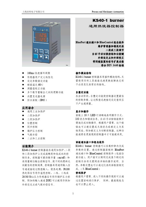
100ms 快速循环周期 传感器用户定义线性化 设定参数锁定功能 耐高温达60 测量值校正功能多个数字量输出之间的逻辑功能 内置变送器电源防水面板IP65应用场合通用工业加热炉 二段加热炉 三段加热炉 位置控制 同步控制锅炉压力控制 气候补偿二点和三点控制功能简介KS40-1 burner 控制器能在通用加热炉二段和三段加热炉上完成高精度和低成本的控制任务控制器可提供数字量on/off 和连续量阀位输出控制信号使不同的燃料达到最佳的控制效果控制器采用通用输入信号通道接收过程值输入使热电偶Pt100热电阻信号用作温度控制二线三线或20/30/50压力传感器信号用作锅炉压力控制附加的输入通道INP2可以被用作例如外部设定点或气候补偿信号KS40-1 burner通用燃烧器控制器BluePort 通讯端口和BlueControl 组态软件维护管理器和错误列表二段或三段调节自动/手动切换按钮和功能键外部设定点和外部校正 带闭锁装置的信号扩展功能符合DIN 3440标准插件模块结构KS40-1 burner 控制器采用插件模块结构无需使用任何工具就能迅速更换故障表芯而不必改变仪表背后的接线自整定功能在启动阶段自整定功能使控制器设置最佳的控制参数让过程值迅速接近设定值而且不产生超调量显示和操作面板上10只LED 灯清晰地表明操作方式I/O 状态和错误信息自动/手动按钮能够方便地完成切换操作根据用户需要这个按钮也可以被设置成无效状态或被定义为其他用途例如被定义为切断控制器这种功能通常在更高级别控制器中才可能被采用面板通讯接口和组态软件KS40-1 burner 控制器可以在数秒钟内完成参数的设置通过控制器面板的BluePort 通讯端口和BlueControl 控制软件包括仿真功能用户就可以顺利完成某个特定的控制任务而无需阅读详细的操作说明当然参数设置也可以通过仪表的面板按钮完成见BlueControl 密码保护根据用户需要进入不同的操作级别可以通过设置密码进行保护 同样最高级组态也可以禁止进入技术参数信号输入1. 功能介绍 输入信号功能INP1 x过程值INP2 SP.E.外部设定值或外部校正值di2可选 控制模式选择模拟量/数字量di3可选禁止操作切换到第2设定值SP2外部设定值SP.E.输出信号保持Y2手动操作控制器中断自动/手动按钮失效存储报警复位2. 过程值输入INP1 分辨率>14位小数点0~3位限制频率2 Hz数字滤波0.000~9999s 可调 采样周期100ms测量值校正2点或偏差校正 L J K N S R热电偶输入输入阻抗1M信号电阻影响1V /冷端补偿最大误差0.5K传感器断路监控输入回路电流1 A 热电阻输入类型Pt100Pt1000KTY11-6连接三线制导线电阻max.30输入回路监控断路和短路 电位计输入连接,例如50-30-50 电流和电压输入信号范围0~10V/0~20mA误差范围0.1%输入电阻110k 电压输入49电流输入量程设置信号范围内可以任意设定刻度范围-1999~9999可调线性化16段可用BlueControl 软件设置小数点可任意调整输入回路监控低于量程起点12.5%2mA,1V变送器电源可选三线制变送器电源电压18V/22mA测量范围0~10V二线制变送器电源电压18V/22mA测量范围4~20mA3. 附加输入INP2 分辨率>14位 采样周期100ms误差0.5% 电流检测输入电阻约15测量范围0~20mA 可组态 刻度-1999~9999A 可调输入回路监控低于量程起点12.5% 4~20mA 2mA 电位计输入 连接三线制量程160/450/1600刻度范围-1999~9999可调 输入回路监控断路和短路 热电阻输入 连接三线制量程Pt100Pt1000输入回路监控断路和短路 控制输入可选 开关电压5V开关电流160 A 变送器电源可选 输出22mA/18V信号输出 1功能介绍 输出信号 功能选项OUT1 控制输出Y1OUT2 控制输出Y2 OUT3限定值触点 控制输出Y1Y2限定值触点 报警 **所有的逻辑信号都能够被或连接2 继电器输出OUT1OUT2 触点常开共用一个公共端最大触点容量500V A 250V AC 2A48~62Hz 阻性负载最小触点容量6V 1mA DC 操作寿命最大容量下800,000次3 OUT3作为继电器输出触点常开和常闭共用一个公共端最大触点容量500V A 250VAC2A48~62Hz阻性负载最小触点容量5V 10mA AC/DC操作寿命最大容量下600,000次如果用继电器输出OUT1~OUT3操作外接电流接触器必需采用RC 缓冲电路以防止过高的关断电压峰值功能1 控制功能迟滞可调整的信号指示器on/off控制器3点信号指示器3段 PID 控制器2点/Y/Off 或2点控制器具有从部分到满负载转换功能2PID 加热/冷却 3点步进控制3点步进控制转换到信号指示器2段 3点步进控制转换到3点信号指示器3段控制参数设置可以通过参数自整定功能或面板按钮手动操作或者由BlueControl 软件完成2 设定点功能设定点梯度可调0.01~9999/min 设定点控制设定点/串级控制带外部校正的设定点气候控制 3 传感器断路/短路故障时输出 切断控制输出切换至安全输出值平均输出值仅限为PID控制器5信号限制功能Max Min 或Max/Min监控信号过程值控制偏差 控制偏差启动或设定点变化时抑制 有效设定点 输出信号Y功能输入信号监控带闭锁功能的输入信号监控通过面板按钮或数字量输入复位几个监控或报警信号可以在输出前采用逻辑或连接应用于执行机构产生一个中断信号或通用报警信号等 6报警功能传感器短路或断路根据不同的信号输入类型监测输入信号的断路和短路维护管理器在错误信息列表中显示故障信号警告和闭锁信息闭锁的信号可以被手动复位故障信息传感器短路断路和反极性加热电流报警控制回路报警参数自整定故障闭锁限制信息重新校准警告信息执行机构动作中断内部故障RAM, EEPROM 等操作和显示 1显示过程值10.5mm LED 设定值7.8mm LED2功能键控制模式选择 操作闭锁切换到第二设定点SP.2 切换到外部设定点SP.E 切换到设定点校正SP.E 切换到固定输出Y2 手动操作 控制器关闭使自动/手动切换失效 锁定报警复位2面板功能说明供电由选型决定 AC 电源电压 90~260V AC频率 48~62Hz功耗 约7V A 24V UC 电源AC电压20.4~26.4V AC频率 48~62Hz DC电压18~31VDC功耗 约7V A W当电源故障时组态参数设定点和控制方式在EEPROM 中可稳定保存BLUEPORT 通讯端口由PC 通讯适配器见附件与PC 机连接采用BlueControl 软件进行控制器组态参数设置和操作环境条件防护等级面板IP65NEMA 4X外壳IP20端子IP00温度 高精度控制0~60预热时间<15min 温度影响<100ppm/K 运行温度-20~65 储存温度-40~70湿度年平均75%相对湿度不结露 撞击和震动防震符合Fc测试DIN68-2-6防撞击符合Ea 测试DIN IEC 86-2-27 电磁兼容性符合EN 61 326-1概要外壳 材质Makrolon 9415阻燃材料易燃等级UL 94 VO 自熄灭 安全测试符合EN 61010-1VDE 0411-1过电压等级II 污染级别2工作电压范围300V AC 保护等级II 认证 符合DIN 3440符合UL 认证电气连接 1 6.3mm 或2 2.8mm 接插件 安装 采用2个夹钳在控制器上/下或左/右安装在仪表盘面重量 0.27kg9.52 oz附件 操作说明书 2个固定夹钳可选设备 BlueControl 工程师软件BlueControl 是基于Windows95/98/NT/2000下的控制器编程软件可以用来对控制器进行组态参数设置以及对KS40-1 burner 控制器的操作另外所有的设置都可以被保存还可以根据需要打印程序的仿真功能可以检测控制器的设置还能进行用户培训观察控制器与控制回路的相互作用只能由BlueControl 软件完成的设置不能由面板按钮设置 用户定义线性化输入/输出的强制功能 调整操作时间和切换周期的限制 调整到60Hz 供电频率根据操作级别设置密码 禁止T1T2循环时间的自动优化 控制器采用PC适配器与电脑相连见附件进行数据交换BlueControl 软件分为Mini Basic 和Expert三个版本具体功能见下表选型清单PC 通讯适配器 9407-998-00001 标准导轨适配器 9407-998-00061 操作手册 9499-040-66011 BlueControl Mini www.pma-online.de BlueControl Basic 9407-999-11001 BlueControl Expert 9407-999-11011端子接线:外形尺寸:应用实例:。
BT300--故障代码
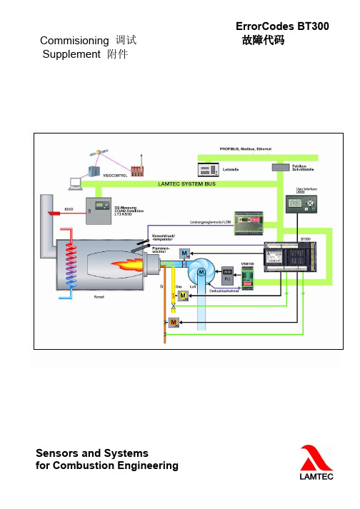
Commisioning 调试ErrorCodes BT300故障代码Supplement附件Sensors and Systemsfor Combustion EngineeringTable of Contents目录1GENERAL INFORMATION(通用信息) (3)1.1Validity of these Instructions(说明文件的有效性) (3)2LIST OF FAULT CODES(故障代码一览表) (4)3ASSIGNMENT OF CONFIGURATION FAULT107(配置故障) (12)4ASSIGNMENT OF INTERNAL FAULT999(内部故障) (13)5ASSIGNMENT OF CO/O2CONTROL FAULTS OR INFORMATION(氧含量/可燃气含量控制控制故障信息) (22)21General Information通用信息1General Information1.1Validity of these Instructions说明文件的有效性This document is a supplement to the Operating Instructions for the LAMTECBurnerTronic BT300listed below.本文件是蓝姆泰克(LAMTEC)燃烧控制器BT300操作说明的补充文件。
It is only applicable together with the Operating Instructions for the affected device.它适合于与相关设备的操作说明配套使用。
The specifications in this document refer to the software version BT300v and higherand UI300v and higher.The following functionalities are not available with softwareversions<3.0.本文档中的规格参考BT300v和UI300v,或者他们更高版本。
瑞典百通牌燃烧机

新
二、设备基本结构: 设备基本结构:
晋
员
工
培
训
新
二、设备基本结构: 设备基本结构:
1、电磁气阀调校: 、电磁气阀调校:
晋
员
工
培
训
电磁气阀组合组件说明图
电磁气阀流量调校:启动气量、低段、高段 将旋钮 左旋:增加输出气量 右旋:减少输出气量
稳压阀调校:
左旋:减低输出压力 右旋:增高输出压力
低压保险器调校:(检测燃气压力。燃气压 力突然大幅减低,燃烧机停止,当燃气压力 回升,燃烧机自动重新开动) 将黄色旋钮向较高压力,直 至燃烧机停止,记下压力,将其下调25%, 就是低气压保险器上的调压。(即正常燃气 压力降低25%,则低压保险器动作)
新
三、常见故障与维修: 常见故障与维修:
故障现象(1):接通电源,燃烧机不启动。 可能原因 烧机
晋
员
工
培
训
:电源未接通或者接线松脱;低风压保险器接触点启动前粘合在“工作状态”;控制盒,风门伺服马达或燃
马达出了问题。 故障现象(2):燃烧机正常启动,但在“吹风程序”其间中断操作,控制盒亮起故障灯号。 可能原因 塞); :控制盒有问题;低风压保险器一直粘合在“闲置状态”(调校压力过高,本身故障,风压过低,气管堵
新
三、常见故障与维修: 常见故障与维修:
故障现象(5):燃烧机不能顺畅地建立火焰,或着火时发出异常声音。 可能原因
晋
员
工
培
训
:炉膛阻力太高(炉膛本身内压太高,排烟管口径太小,检查排烟通道是否阻塞)
故障现象(6):燃烧机时而无缘无故停止操作,控制盒不亮故障灯号。 可能原因 :电压问题,过低停止,稍后回升自行重新启动;燃气供应压力不足导致喷出火焰时压力急剧下降停止,然 后回升重新启动;低气压保险器调校压力不正确。 故障现象(7):燃烧机时而无缘无故停止操作,控制盒亮起故障灯号。 可能原因 :火焰信号问题;大量灰尘污垢;风压信号问题。
百德燃烧器

未知驱动探索,专注成就专业
百德燃烧器
百德燃烧器(Bder Burner)是一种可燃烧液体或气体燃料的设备,常用于工业应用中,如加热锅炉、工厂炉子、热水器等。
百德燃烧器具有高效、节能和环保等特点,能够将燃料完全燃烧,减少尾气排放和能源浪费。
百德燃烧器采用先进的燃烧技术,通过控制燃料与空气的混合比例,使燃料在燃烧过程中达到最佳状态,提高燃烧效率,减少燃料的消耗。
同时,百德燃烧器还配备了多重安全保护装置,确保设备运行的安全稳定。
百德燃烧器适用于各种燃料类型,包括天然气、液化石油气、柴油和重油等。
根据不同的应用需求,百德燃烧器还可以提供定制化的解决方案,满足客户的特殊要求。
总的来说,百德燃烧器是一种高效、可靠的设备,广泛应用于工业领域,为用户提供了节能、环保的解决方案。
1。
百得燃烧机工作原理
百得燃烧机工作原理
百得燃烧机的工作原理是利用燃油和空气的混合物在特定的燃烧室内燃烧产生高温高压气体,从而产生能量。
具体工作原理如下:
1. 燃料供给:百得燃烧机通过燃油喷嘴将燃料(如液化石油气、天然气等)喷入燃烧器内。
燃油进入燃烧器后会与空气混合。
2. 空气供给:空气通过风机被吸入燃烧器,与燃油混合形成可燃气体。
燃烧机通常有自动化的控制系统,可以根据需要调节空气的供给量,以实现燃烧的效果和稳定性。
3. 燃烧过程:燃油和空气的混合物进入燃烧室,燃烧器内点火系统产生火花点燃混合物。
燃油的燃烧需要足够的氧气,因此空气的供给量要适当。
点燃后,混合物会燃烧产生高温高压气体。
4. 热能利用:燃烧产生的高温高压气体通过燃烧室内的热交换器(通常是烟气管道)传递给所需的介质(如水、空气等)。
在热交换过程中,热能被转移到介质中,使其升温。
可以利用这一热能来提供动力、供暖或产生蒸汽等。
总的来说,百得燃烧机工作原理主要包括燃料供给、空气供给、燃烧过程和热能利用。
通过合理调节燃料和空气的混合比例,可以实现高效的燃烧过程,从而产生所需的热能和动力。
- 1、下载文档前请自行甄别文档内容的完整性,平台不提供额外的编辑、内容补充、找答案等附加服务。
- 2、"仅部分预览"的文档,不可在线预览部分如存在完整性等问题,可反馈申请退款(可完整预览的文档不适用该条件!)。
- 3、如文档侵犯您的权益,请联系客服反馈,我们会尽快为您处理(人工客服工作时间:9:00-18:30)。
1.0
用户快速指南- Lamtec BT 300 rel
起始界面: 保持温控器断开-> 燃烧器保持待机
对程控器解锁: 按ENTER键
信息手动设置
点击Right键到Settings(设置)
按 ENTER键
再次按 ENTER 键
保持密码“0000“ 并按ENTER键确认
新的页面
第1 层解锁
点击Right(右)键到EDIT(编辑)
按ENTER 键
在燃烧器点火时空气和燃气位置
按ENTER 键修改位置 (燃烧器在待机状态)
点火位置
燃气伺服电机位置 空气伺服电机位置
按UP(上)键增加燃气打开位置或者DOWN(下)键减少打开位置
点击Right键到AIR(空气)开启位置,同样通过UP和DOWN键增加或者减少打开位置
按ENTER键保存新的设置
闭合温控器 -> 燃烧器启动
预吹扫
程控器驱动伺服马达到点火位置,然后启动点火变压器
如果燃烧器带有这些设置启动,以下页面将显示:
带有这些设置但是燃烧器没有启动,参见15页
检查燃烧质量(带有一个烟气分析仪).
按ENTER键修改设置 ->如第6页介绍的修改设置-> 按 ENTER 键保存最好的设置
点击UP键离开点火位置
检查在所有位置的燃烧质量(从最小出力到最大出力),如果需要调节燃气和空气的设置(如第6页所述进行)
根据锅炉的最大输出要求,设置最大负荷位置999.如果有必要,设置燃气出口压力(在调压阀出口位置处的
压力).检查所有位置的燃烧质量如有必要调节燃气和空气(参看第6页).
按 EXIT键离开燃烧设置菜单
次按EXIT 键离开主菜单再
再次按 EXIT 键离开设置菜单
燃烧器现在运行在自动状态
检查锁定代码或者按ENTER 键解锁 如果点火设置不是足够的好 (比如空气太多), 燃烧器不能启动. 在这种情况下,再次调节点火位置(参见第6页) . 否则,可以确认这里没有其他的原因可能引起点火失败.
故障? 在显示屏上将显示原因如果有故障, 燃烧器将进入锁定模式。