Codian MCU中文简明使用手册v2
Mcu配置使用手册

视频会议服务器MCU 配置使用手册福州易达信软件科技有限公司2007年9月20日目录概述: (3)1.流媒体服务器搭建 (3)1.1 IIS服务器 (3)1) 安装 (3)2) 添加虚拟目录 (4)3) 修改MCU配置文件 (4)1.2 Windows Media Server服务器 (5)1) 添加Windows Media Server 组件 (5)2) 新建发布点 (5)3) 修改配置文件 (8)2. GNUGK安装和配置 (9)2.1 GunGK 安装 (9)2.2 GunGK 配置文件 (12)2.3 设置MCU登陆网守 (13)3. MCU的安装配置 (14)3.1 数据库配置 (14)1) 附加数据库 (14)2) MCU数据库配置 (15)3.2 虚拟打印机的安装和设置 (16)1) 安装 (16)2) 配置默认打印机 (16)3) 打印机设置 (17)4) 配置MCU配置文件 (17)3.3 MCU启动和配置 (17)1) 配置登陆网守 (18)2) 设置音频 (19)3) 设置视频 (19)4) 设置网络 (20)3.4 MCU日常使用 (21)1)MCU主界面 (21)2)MCU工具条 (22)3)添加用户 (22)4)删除用户 (23)Vccp登陆 (23)概述:视频服务器主要由流媒体服务器、GnuGK和MCU组成,因此安装视频服务器的过程也是在安装这三种服务的过程。
1.流媒体服务器搭建流媒体服务器:负责媒体文件的点播。
现在市面上有几种流媒体服务器,达尔文服务器、Windows Media Server、RealServer,其中它们分别负责mov、wmv/wma、及RM格式文件的点播,经测试发现微软平台自带的IIS组件也可以搭建成一定意义上的流媒体服务器,即在IIS中的RM文件,在Realplayer中也可边下载边播,因此视频流媒体服务器很多时候是采用IIS。
然而IIS并不支持WMV格式的“边下载边放”,因此如果需要支持WMV格式的“边下载边放”,则必须安装Windows Media Server。
MCU使用手册

第 7 页 ,共 46 页
7
点击 Disconnect ,出现对话框如下。
文件编号: longhu-003
点击确定按钮 ,与 MCU 的连接即可断开。 关于自动登陆
如果你需要频繁地登陆到 MCU,每次输入密码都是非常麻烦的事情,你可以通过创建 一个登陆记录来自动登陆到 MCU。 注:此设置仅针对不存在系统安全问题并希望简化操作步骤时使用 创建登陆记录
定义如下参数
第 9 页 ,共 46 页
9
文件编号: longhu-003
参数
描述
MCU Date Parameters 这些参数显示 MCU 当前定义的年,月,日。这些参数同样允
Month/Year
许你通过下拉菜单来做新的设置。
Operator Local Time and 显示 MGC Manager 上设置的日期和时间(这个时间来源于
Get Oper Time & GMT 根据 MGC Manager 自动更新 MCU 的时区,日期与时间
Get Oper Time Offset 根据 MGC Manager 的时间自动更新 MCU 的时间(没有时差)
六.定义各项服务
进入 MCU ConfigurationNetwork Services 界面,如下图:
第五章 问题诊断.........................................................................................................................39 一、常见问题解答.................................................................................................................39 二、故障诊断分析.................................................................................................................42
哈希COD使用手册

MCU系统管理员操作手册

-
系
统
第三十四页,共52页,
系统管理员操作手册
系
统
xì
tǒ
n
g
管
理
员
MCU会议内无任何中断时是否对
-
会议进行锁定 suǒ dìnɡ 的处理,
系
统
xì
第三十五页,共52页,
系统管理员操作手册
系
统
xì
tǒ
n
g
管
理
员
终端是否 shì fǒu 可以呼叫MCU会议名
-
称选项,
系
统
xì 第三十六页,共52页,
统
xì 第十二页,共52页,
系统管理员操作手册
系
统
xì
tǒ
n
g
管
动作/清晰度 优先选项:点击下拉菜
理
单,可以设置MCU在召开会议时接收
员
和发送的图像以何种方式优先,在 CICO系统中,由于 yóuyú 终端全部为标
-
清终端,为提升用户的图像质量,需将
系
此设置选为清晰度优先项,
统
xì
第十三页,共52页,
设置
系统管理员-系统设置 系统管理员-用户设置 系统管理员-终端设置
第四十七页,共52页,
系统管理员操作手册
系
统
终端列表 liè biǎo 界面
管
理
员
点击新增H.323,即可
增加新的终端,
-
终
端
z
h
ō
n
第四十八页,共52页,
系统管理员操作手册
系
新增H.323终端 zhōnɡ
统
duān 界面
COD在线检测仪使用说明书

COD在线检测仪使用说明书目录一、 JHC-Ш型CODcr在线检测仪使用说明书 (3)1. 主要技术指标 (3)2. 有机化合物的测定国标方法 (4)3. 仪器结构简介 (5)4. COD自动检测仪工作步骤 (6)5. 各子系统功能工况祥解 (9)6. 微机控制系统原理 (11)7. 主菜单选择及功能 (12)8. 仪器维护与保养 (13)9. 仪器故障显示及处理 (14)二、 COD 在线分析仪试剂配比 (15)三、易损易耗件一览表 (16)一、主要技术参数与特点1.技术参数测量范围(mg/L):30~950(扩展型1000~4000或4000~10000)测量误差:≤±10%重复误差:≤±5%适用环境温度:5~40℃电源电压(v) :220±10%功率(kw):1.5主机类型:日本三菱公司原装PLC显示方式:彩色触摸显示屏打印机:16位微打(并行口)数据远传接口:RS232,Modem注:根据GB11914-89国家标准,检测COD在50mg/L以下的水样时,需要用低浓度标准溶液。
其测量误差大于本指标。
2.技术特点:⑴仪器测试原理、方法、步骤完全符合国家标准,检测数据准确可靠。
⑵仪器主机采用三菱PLC、彩色触摸屏,图形画面活泼多彩,生动直观,全中文显示,一目了然,操作更方便。
⑶仪器具有较强的远程通讯功能。
通过电话线或无线电与远程终端联系。
⑷仪器若发生故障,现场主机会自动拨通值班电话,向终端计算机报告故障情况。
终端计算机可随时拨通现场电话与现场主机通讯,监控现场仪器的工作情况,调取现场主机一月内任意时间的检测数据结果。
⑸仪器采用全气动移液、定量、加液结构,解决了强腐蚀性药剂对自控元器件的影响,使系统运行更可靠。
⑹仪器集水样采集与COD检测于一体,回流消解采用独特的风冷加静止水套冷却方式,无需自来水水源,使现场应用更为方便。
⑺由PLC控制的精密注射泵完成氧化还原滴定的数据计量,由光电信号准确测得滴定终点,使整个系统的精度、可靠性进一步提高。
mcub02板使用说明

(1) 功率模块插接口:CN1 (2)功率模块插接口:CN2(3) 同步电机编码器扩展接口:CN9 (4)变频控制CPU 在线升级接口:CN5(5) INV 键盘插口:CN3 (6)RS232接口:CN12(7) 异步电机旋转编码器接口:CN11 (8)并联、群控TCAN/RS485接口:FR(1) (2) (4) (5) (6) (7) (8) (9) (10) (11) (12) (13) (14) (16)(15)(17)(18) (19) (20)(21)(22)(23) (25) (26)(24) (3)(9) 板载+48V 继电器:15BX (MY4) (10)板载+48V 继电器:50B (MY4) (11)运行接触器驱动端子:Z10 (12)板载+48V 继电器:40D (MY4) (13)抱闸接触器驱动端子:Z15B (14)板载+48V 继电器:100R (MY4) (15)+48V 信号输出接口:FE (16)+24V 信号输出接口:FD (17)上行强迫减速开关输入接口:SDSU (18)下行强迫减速开关输入接口:SDSD(19)+48V 信号输入接口:FC (20)+24V 信号输入接口: FB (21)+24V 信号输入接口:FA (22)串行通讯接口:SCL (23)小键盘(3键) (24)七段LED 显示(3位)(25)串行程序在线升级接口:CN302 (26)变频控制CPU 在线升级接口:CN42.小键盘介绍2.1硬件介绍在MCUB 的右上角有三个小按钮和三个7段数 码显示,称之为小键盘。
通过对小键盘的不同操 作,可以使三个7段数码显示出电梯的不同信息 以及对电梯进行一些操作。
小键盘的外观如右图所示:对应图中左中右三个键分别定义为MODE 、 INC/ST 、SET 键。
2.2 一般操作MCUB 板定义了7个状态号,分别为0、1、2、3、4、5、6,各状态对应的功能见下表(电梯小键盘功能列表)。
Codian_MCU简单使用手册

Codian MCU 用户手册目录第一章安装 (3)1.连接 MCU到您的网络 (3)2.设置 MCU的网络IP地址 (4)第二章登陆及设置 (4)1.登陆 MCU (4)2.MCU状态显示 (5)3.MCU网络设置 (7)4.MCU详细设置 (8)5.MCU会议设置 (10)6.MCU用户设置 (13)7.MCU终端设置 (13)第三章会议控制 (15)会议中的操作 (15)第一章安装1.连接 MCU到您的网络这一部分主要讲解安装 MCU以及登陆IPVCR的一些操作和命令。
在您对 MCU设备进行加电之前:使用蓝色的串口线缆连接至 MCU的串口启用您的串口程序,并按照以下接口数据进行连接使用网线连接 MCU的以太网口A至您的以太网交换机(非Hub) MCU的以太网速率支持10/100/1000Mbps自动协商连接电源线,开启电源MCU没有on/off的电源开关2.设置 MCU的网络IP地址默认用户名》admin 密码:无等到 MCU面板上的红色警告灯熄灭后,在您的串口程序上就可以直接进行命令行的操作了。
MCU默认为DHCP模式,当然您也可以手动设定固定IP地址。
手动设定DHCP的命令如下:手动设定固定IP地址的命令如下:如若没有DNS服务器,您可以设定您的默认网管地址------其中的任何一项都需要设定检查IP设定的状态命令---status,察看命令的命令---help,察看命令语法的命令---“命令”+“回车”。
第二章登陆及设置1.登陆 MCU打开IE浏览器(或者FireFox),在地址栏输入MCU的IP地址。
注意:保证此地址可通过电脑访问。
登陆后,点击登陆MCU,进入下一页面。
默认情况下,Codian MCU是以Guest用户组登陆,此时可以点击播放一些开放的流媒体会议。
如果希望进行会议的创建和控制,需要管理员用户权限。
要以管理员身份登陆,请点击“更改登陆”。
此时会弹出对话框,要求输入用户名和密码,请以管理员用户名和密码登陆。
CodianMCU简明使用手册

CodianMCU简明使用手册目录一、登录方法................................................................................................... 错误!未定义书签。
二、Codian MCU功能简介 ........................................................................................ 错误!未定义书签。
1.状态...................................................................................................... 错误!未定义书签。
2.网络...................................................................................................... 错误!未定义书签。
3.设置...................................................................................................... 错误!未定义书签。
4.会议...................................................................................................... 错误!未定义书签。
5.用户...................................................................................................... 错误!未定义书签。
MCU使用指南

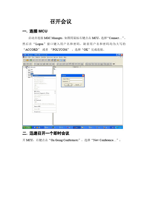
召开会议一. 连接MCU启动并连接MGC Manager,如图用鼠标右键点击MCU,选择“Connect…”,然后在“Logon”窗口键入用户名和密码。
缺省用户名和密码均为大写的“ACCORD”或者“POLYCOM”,选择“OK”完成连接。
二. 迅速召开一个即时会议开MCU,右键点击“On Going Conferences”,选择“New Conference…”;出现如下窗口后,在“Name”栏中键入会议名称,在“Conf.Entry”中输入需要设置的会议密码,在“Duration”栏中键入会议共召开多长时间,注意会议时间最长为99小时,缺省值为2小时,然后选择所需要召开的会议相关类型在Video Session栏中选择符合自己需求的会议模式。
Video Switching表示所有与会者连接的速率都是一样的;Transcoding表示允许与会者连接会议的速率不一样;Continuous Presence表示不但允许与会者连接会议的速率不一样,而且该会议还带分屏方式;Software CP为软件分屏的功能,不需要硬件Video板卡,但受相应IP板卡数目限制,在Conference Type中的Standard为默认会议属性Meeting Room为聊天室会议,会议中不需要定义参加会场,分会场直接拨叫会议名称即可。
*此功能需要Gatekeeper支持Operator用于Greet & Guide(迎接与引导)功能。
*此功能为选项Meet Me Per Conference功能在Gatekeeper支持情况下,可实现定义部分会场与部分会场直接拨叫会议名称两种方式共用Remarks栏可以对会议做标记,例如标记会议由哪个部门召开,重要性等。
Supported Network仅为区分是否在完全的IP(H323)模式,如为此模式,则可选择Software CP功能。
完成以上窗口后,在窗口栏上选择“Settings”。
MCU快速上手指南

MCU 操作快速上手指南2007年11月目录第一章MGC MANAGER软件操作 (3)1会议前准备 (3)1.1 安装MGC manager (3)1.2 定义及修改MCU的控制IP地址 (5)1.3 开始使用MGC MANAGER 管理MCU (7)1.4 定义各项服务 (7)2召开总-分-支行的视频会议(带双流) (14)2.1 连接MCU (14)2.2 召开一个即时会议 (14)3.召开分-支行的视频会议(带双流) (18)3.1 连接MCU (18)3.2 召开一个即时会议 (18)4.如何保存会议 (22)5.如何断开会议 (23)6.监控会议 (24)6.1 监控与会者的操作 (24)6.2 控制会议的操作 (28)第一章MGC MANAGER软件操作1会议前准备1.1 安装MGC manager1.放入光盘到光盘驱动器中,运行setup,安装程序向导会出现版权事项,点击“Next”,出现如下界面:2.点击Next,会出现如下界面:3.在相应位置输入“用户名”以及公司的名称,点击Next,显示如下界面:4.选择要安装MGC Manager软件的路径,如果接受默认目录,点击Next。
如要更改目录,点击Browse,选择要安装的目录,点击Next显示如下界面:5.选择要安装MGC Manager图标的程序目录,如接受默认设置,点击Next,检查所有安装信息是否正确。
如要更改设置,点击Back直到出现相应的屏幕。
点击Next 后开始拷贝文件到你的硬盘中。
当安装程序完成后,会显示如下界面:6.点击Finish。
MGC Manager现在已经安装到你的计算机中。
1.2 定义及修改MCU的控制IP地址运行MGC Manager,如下图:2.创建一个新的MCU右键点击MCUs Metwork,左键点击New MCU●键入MCU初始网络参数,点OK●在新创建的MCU图标上点击右键,然后左键点connect…●键入用户名和密码,初始都为大写POL YCOM1.3 开始使用MGC MANAGER 管理MCU●启动MGC Manager●连接到MCU●连通MCU以后,显示如下界面。
哈希COD使用说明书

DOC023.52.03233.Jan04CODmax 化学需氧量分析仪操作手册○C HACH LANGE 2004. All rights reserved.致力优质水质目录第一章技术规格 (4)第二章引言 (5)2.1 系统描述 (5)2.2 应用 (6)第三章拆箱和安装 (7)3.1 拆箱和安装…………………………………………………………………………‥ 73.1.1安装位置要求…………………………………………………………‥•‥‥ 73.2 MODBUS界面……………………………………………………………………‥•103.2.1 MODBUS协议 (11)3.2.2连接……………………………………………………………………………• 113.2.3 MODBUS网卡 (11)3.2.4输出特性表……………………………………………………………………• 12第四章校准与准备试剂…………………………………………………………………• 164.1 试剂成份 (16)4.1.1 硫酸汞溶液 (16)4.1.2 重铬酸钾溶液 (18)4.1.3 硫酸溶液 (18)4.1.4 零点标准溶液 (19)4.1.5 标准溶液 (19)4.1.5.1 标准溶液的化测试验 (19)4.2 危害信息 (20)第五章试运行分析仪 (22)5.1 拆卸安全面板 (22)5.2 安装试剂 (23)5.3 暂停操作 (25)第六章操作…………………………………………………………………………………• 266.1 基本原理 (26)6.2 测试范围 (26)6.3 测试步骤 (26)6.4 校准 (27)6.5 自动清洗 (27)6.6 手动清洗 (27)6.7 安全面板 (27)6.8 湿度传感器 (28)6.9 分析单元 (29)6.10 导管分布图…………………………………………………………………………• 306.11 样品泵操作…………………………………………………………………………• 32第七章软件菜单系统……………………………………………………………………• 327.1 主显示屏……………………………………………………………………………‥ 327.2 键盘使用……………………………………………………………………………‥ 337.2.1 图形功能 (34)7.3 菜单结构……………………………………………………………………………‥ 357.3.1 设置菜单 (35)7.3.2 信号菜单 (36)7.3.3 维修菜单 (38)测试功能菜单…………………………………………………………• 397.3.3.17.3.4 状态菜单 (40)7.4 记录COD数据 (40)第八章设备维护 (42)第九章故障维修 (47)9.1 警告 (47)9.2 错误 (47)第十章附件列表 (50)安全预防措施尤其注意所有有关危险和谨慎问题的说明。
多点控制单元MCU操作规范指南规范.doc

多点控制单元MCU-操作指南2019-07-20目录第1章配置安装 (3)1.1安装前的准备 (3)1.2 管理界面 (3)1.3建立会议模板 (5)1.4添加地址簿 (11)1.5召开即时会议 (13)第2章操作管理会议 (15)2.1会议属性管理 (15)2.2与会者管理 (17)2.3修改分屏/演讲者 (19)2.3.1 修改分屏 (19)2.3.2 更换演讲者 (20)2.4会议模式 (20)2.4.1演讲者模式 (20)2.4.2相同分屏模式 (21)第3章日常维护及故障处理 (22)3.1与会者观看的画面质量不高 (22)3.2与会者听不到声音 (23)3.3无法呼叫与会者 (24)3.4与外部网络不通 (24)第1章配置安装1.1安装前的准备打开的包装,你会看到如下几样东西:➢附件:包括电源线,网线等,这些装在一个盒子里➢机架附件:用于将MCU安装在19寸机架➢许可:根据用户购买的资源点数或者其他附加功能,包装内会包含许可除此之外,我们还需要了解:用户为这台MCU分配的相关IP地址,包含一个信令ip,一个控制ip,一个机框ip,一到两个媒体ip。
1.2管理界面下图是的管理界面,我们可以看到整个界面可以分为六大部分:RMX管理:负责所有MCU相关配置的,在这里可以配置NETWORK SERVICE,会议模板,查看硬件状态等等。
会议列表:所有召开的会议都会在这个界面列出与会者列表:列出当前你选择查看的会议的与会者,如果你选择了两个会议,那么会同时列出这两个会议的所有与会者。
状态栏:列出目前MCU的状态和资源占用情况,提示目前是否有活动告警或者与会者告警。
地址簿:列出MCU中保存的地址簿信息。
除此之外,管理界面左上角还有四个菜单键,可以进行查看系统信息,收集LOG等操作1.3建立会议模板会议模板是MCU召开会议的基础,绝大部分关于会议的相关配置都是在会议模板中进行定义的,模板中已经定义好的参数,在会议召开过程,是无法改的的(少部分可以)。
Si102X Si103X 无线MCU快速入门指南说明书

Rev. 0.2 11/11Copyright © 2011 by Silicon LaboratoriesSi102x/3x QSG1. IntroductionThis application note will help you get a quick start on demonstration, evaluation, or code development with the Si102x/3x products.1.1. Choose between Evaluation, Demonstration, or Code Development⏹Evaluate the radio performance or experiment with register settings:1.Install one UDP Si102x/3x UPPI Pico Board on the provided MCU card. The white triangles on the boards should line up.2.(Optional) Install the MCU card on the UDP motherboard.3.Download the demonstration host firmware to the Si102x/3x MCU.4.Install WDS and connect.5.More information on WDS can be found at the link in "1.3. Wireless Development Suite (WDS)" on page 2.⏹Compile and Download RF demonstrationfirmware:1.Install one UDP Si102x/3x UPPI Pico Board on the provided MCU card. The white triangles on the boards should line up.2.(Optional) Install the MCU card on the UDP motherboard.3.Install the Silicon Labs Integrated Development Environment (IDE).4.Install an evaluation version of a C compiler.5.Open →modify →build →download →go.6.Skip to "1.4. Code Development" on page 3.RF Test EquipmentMCU Card MCU cardPico BoardPico BoardSi102x/3x QSG1.2. Kit ContentsThe kit contents for the two types of Si102x/3x development kits are listed below:Software Development Kit⏹ 2 Si102x/3x UPPI Pico Boards.⏹ 2 UDP MCU cards.⏹ 2 antennas.⏹ 2 Lithium batteries.⏹Silicon Laboratories USB Debug Adapter.⏹Supporting cables.⏹Development Kit CD.⏹Si102x/3x Quick Start Guide (this document).Wireless Development Kit⏹ 2 Si102x/3x UPPI Pico Boards.⏹ 2 UDP MCU cards.⏹ 2 antennas.⏹ 2 Lithium batteries.⏹ 2 UDP Motherboards.⏹ 2 I/O cards.⏹Silicon Laboratories USB Debug Adapter.⏹Supporting cables.⏹Development Kit CD.⏹Si102x/3x Quick Start Guide (this document).1.3. Wireless Development Suite (WDS)Using the WDS Chip Configurator software is the best way to evaluate the RF performance in the lab with a PC invarious configurations. The WDS GUI provides a convenient way to run configuration scripts and to change the radio settings bit-by-bit.The WDS GUI can be found on the Silicon Laboratories website: /wds .RF Test EquipmentMCU Card MCU cardPico BoardSi102x/3x QSG 1.4. Code DevelopmentPicoBoardA number of RF programming examples are included with the standard Silicon Laboratories IDE installation. This section will describe how to start building and running one of these examples.1.4.1. Running the TX Spectrum Example1.Install the Silicon Labs IDE software. Use the included CD or download from .2.Install a C compiler. This example uses SDCC. A list of compiler links is available on the Silicon Laboratorieswebsite: /products/mcu/Pages/DevelopmentTools.aspx3.Connect the USB Debug Adapter to your computer.4.Install a Si102x/3x 915MHz radio card on the provided MCU card.5.(Optional) Install the MCU card on the UDP motherboard.6.Move the MCU card SW5 VBAT switch to the middle VREG position.7.Move the MCU card SW7 VIO switch to the upper VBAT position.8.Move the MCU card SW12 VIORF switch to the upper VBAT position.9.Connect the USB Debug Adapter ribbon cable to J13 on the MCU card.10.Connect power.unch the Silicon Labs IDE software: All Programs→Silicon Laboratories→Silicon Laboratories IDE.12.Select the SDCC compiler.a. Project →Tool Chain Integration …b. Select the SDCC preset.c. Click OK.Si102x/3x QSG13.Establish a connection to the Si102x/3x device: Debug →Connect.14.Open the Si102xx_TxSpectrum.c file.(path: C:\SiLabs\MCU\Examples\Si102x_3x\EZRadioPRO\TxSpectrum\Si102x_3x_TxSpectrum.c).15.Ensure the correct Pico board is selected as a target at the top of the file.16.Change the frequency to 913MHz in the setTRxFrequency() function call in main.17.Fine-tune the EVB's crystal frequency. Scroll down to the RadioInit() function and add a phyWrite() command:18.Build the project and download the the device:a. Press ctrl-shift-F7 to compile and build.b. Press the [DL ] Icon to download.c. Ensure Download Successful appears in the Output Window at the bottom of the IDE.19.Run the code by pressing F5.20.Connect a spectrum analyzer to the antenna port and verify the modulated spectrum.1.4.2. General Silicon Laboratories IDE Code Download Procedure1.Install the Silicon Labs IDE software. Use the included CD or download from .2.Connect the USB Debug Adapter to your computer.3.Plug the UPPI Pico Board in to the UDP MCU card.4.(Optional) Install the MCU card on the UDP motherboard.5.Move the MCU card SW5 VBAT switch to the middle VREG position.6.Move the MCU card SW7 VIO switch to the upper VBAT position.7.Move the MCU card SW12 VIORF switch to the upper VBAT position.8.Connect the USB Debug Adapter ribbon cable to J13 on the MCU card.9.Connect power.unch the Silicon Labs IDE software: All Programs → Silicon Laboratories -> Silicon Laboratories IDE.11.Establish a connection to the Si102x/3x device: Debug → Connect.12.Select the hex file to download: Debug → Download Object File. Choose the file, then select Download to initiate the programming.13.Verify the successful download.14.Disconnect the connection from IDE to Si102x/3x device: Debug → Disconnect.15.Disconnect the USB Debug Adapter ribbon cable.16.Reset by cycling the power.Si102x/3x QSG 2. For More InformationDevice data sheets⏹Si102x/Si103xEvaluation board information⏹UDP Motherboard, MCU card, Pico Board, and I/O card User’s Guides (/udp)⏹RF card schematics and PCB layout ()Register information, programming guides, and examples⏹AN440: Si4430/31/32 Register Descriptions⏹AN415: EZRadioPRO® Programming Guide⏹AN417: Si4x3x Family Crystal Oscillators⏹Si102x/Si103x MCU Example Code (included as part of the IDE installer)Lab testing and evaluation⏹AN439: EZRadioPRO® RF Testing Quick-Start Guide⏹AN437: Si4432 RF Performance and FCC Compliance Test Results⏹AN445: Si4431 RF Performance and ETSI Compliance Test Results⏹AN459: Measurement Results for Si4430-B and 950 MHz ARIB STD-T96 ComplianceDesign⏹AN435: Si4032/4432 PA Matching⏹AN436: Si4030/4031/4430/4431 PA Matching⏹AN463: Raw Data Mode with EZRadioPRO®3. Contact InformationPlease visit the Silicon Labs Technical Support web page:https:///support/pages/contacttechnicalsupport.aspxand register to submit a technical support request.DisclaimerSilicon Laboratories intends to provide customers with the latest, accurate, and in-depth documentation of all peripherals and modules available for system and software implementers using or intending to use the Silicon Laboratories products. Characterization data, available modules and peripherals, memory sizes and memory addresses refer to each specific device, and "Typical" parameters provided can and do vary in different applications. Application examples described herein are for illustrative purposes only. Silicon Laboratories reserves the right to make changes without further notice and limitation to product information, specifications, and descriptions herein, and does not give warranties as to the accuracy or completeness of the included information. Silicon Laboratories shall have no liability for the consequences of use of the information supplied herein. This document does not imply or express copyright licenses granted hereunder to design or fabricate any integrated circuits. The products must not be used within any Life Support System without the specific written consent of Silicon Laboratories. A "Life Support System" is any product or system intended to support or sustain life and/or health, which, if it fails, can be reasonably expected to result in significant personal injury or death. Silicon Laboratories products are generally not intended for military applications. Silicon Laboratories products shall under no circumstances be used in weapons of mass destruction including (but not limited to) nuclear, biological or chemical weapons, or missiles capable of delivering such weapons.Trademark InformationSilicon Laboratories Inc., Silicon Laboratories, Silicon Labs, SiLabs and the Silicon Labs logo, CMEMS®, EFM, EFM32, EFR, Energy Micro, Energy Micro logo and combinations thereof, "the world’s most energy friendly microcontrollers", Ember®, EZLink®, EZMac®, EZRadio®, EZRadioPRO®, DSPLL®, ISOmodem ®, Precision32®, ProSLIC®, SiPHY®, USBXpress® and others are trademarks or registered trademarks of Silicon Laboratories Inc. ARM, CORTEX, Cortex-M3 and THUMB are trademarks or registered trademarks of ARM Holdings. Keil is a registered trademark of ARM Limited. All other products or brand names mentioned herein are trademarks of their respective holders.Silicon Laboratories Inc.400 West Cesar Chavez Austin, TX 78701USAIoT Portfolio /IoTSW/HW/simplicityQuality/qualitySupport and Community。
卡莫茨tmcu, tmvu, tmco流量控制阀手册说明书

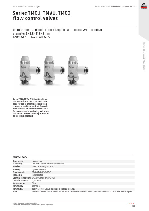
S E R I E S T M C U , T M V U , T M C O V A L V E SSeries TMCU, TMVU, TMCO flow control valvesUnidirectional and bidirectional banjo flow controllers with nominal diameter 2 - 3,8 - 5,8 - 8 mm Ports: G1/8, G1/4, G3/8, G1/2Series TMCU, TMVU, TMCO unidirectional and bidirectional flow controllers have been revised in order to decrease their dimensions and improve their flow rate characteristics. Their construction allows for easy assembly to cylinders and valvesand allows the regulation adjustment to be precise and gradual.GENERAL DATAConstruction needle - typeValve group unidirectional and bidirectional controller Materials brass - technopolymer - NBR Mounting by male threaded Threaded ports G1/8 - G1/4 - G3/8 - G1/2Installation in any position Operating temperature 0°C ÷ 60°C (with dry air -20°C)Operating pressure 0,5 ÷ 10 bar Nominal pressure 6 bar Nominal flow see graphNominal dia.Tube 4 Ø2 - Tube 6 Ø3,8 - Tube 8 Ø5,8 - Tube 10 and 12 Ø8Fluidfiltered air. If lubricated air is used, it is recommended to use ISOVG 32 oil. Once applied the lubrication should never be interrupted.S E R I E S T M C U , T M V U , T M C O V A L V E SCODING EXAMPLETo ensure the right choice of unidirectional flow controller, proceed as follows: calculate the quantity of air in Nl/min (see cylinder Table); determine the stroke time of the cylinder; referto graph to see which controller is the right type.S E R I E S T M C U , TMV U , T M C O V A L V ESTUBE Ø4Flow Qn (Nl/min.) from 2 → 1 with controller OPEN: 400 Flow Qn (Nl/min.) from 2 → 1 with controller CLOSED: 280Qn is determined with a supply pressure of 6 bar and with ΔP = 1 bar at the outletN° = number of screw turns.TUBE Ø6Flow Qn (Nl/min.) from 2 → 1 with controller OPEN: 550 Flow Qn (Nl/min.) from 2 → 1 with controller CLOSED: 280Qn is determined with a supply pressure of 6 bar and with ΔP = 1 bar at the outletN° = number of screw turns.UNIDIRECTIONAL AND BIDIRECTIONAL FLOW CONTROL REGULATORSTUBE Ø8Flow Qn (Nl/min.) from 2 → 1 with controller OPEN: 890 Flow Qn (Nl/min.) from 2 → 1 with controller CLOSED: 460Qn is determined with a supply pressure of 6 bar and with ΔP = 1 bar at the outletN° = number of screw turns.TUBE Ø10Flow Qn (Nl/min.) from 2 → 1 with controller OPEN: Ø 10- 1200/Ø12-1250Flow Qn (Nl/min.) from 2 → 1 with controller CLOSED: Ø 10-600/Ø12-600Qn is determined with a supply pressure of 6 bar and with ΔP = 1 bar at the outletN° = number of screw turns.UNIDIRECTIONAL AND BIDIRECTIONAL FLOW CONTROL REGULATORSS E R I E S T M C U , T M V U , T M C O V A L V ESSeries TMCU valvesUnidirectional flow controller for mounting on single-acting or double-acting cylinders.Adjustment of setting by a hexagonal male key or a manually operated knurled screw.Ports: G1/8, G1/4, G3/8, G1/2Series TMVU valvesUnidirectional flow controller for mounting on valves.Adjustment of setting by a hexagonal male key or a manually operated knurled screw.Ports: G1/8, G1/4, G3/8, G1/2Series TMCO valvesBidirectional flow controller.Adjustment of setting by a hexagonal male key or a manually operated knurled screw.Ports: G1/8, G1/4, G3/8, G1/2。
维克ト恩能源生产力系统配置助手说明书

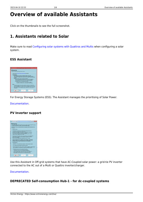
Overview of available AssistantsClick on the thumbnails to see the full screenshot.1. Assistants related to SolarMake sure to read Configuring solar systems with Quattros and Multis when configuring a solar system.ESS AssistantFor Energy Storage Systems (ESS). The Assistant manages the prioritising of Solar Power. Documentation.PV Inverter supportUse this Assistant in Off-grid systems that have AC-Coupled solar power: a grid-tie PV inverter connected to the AC out of a Multi or Quattro inverter/charger.Documentation.DEPRECATED Self-consumption Hub-1 - for dc-coupled systems2022-06-01assistants:overview_of_available_assistants https:///live/assistants:overview_of_available_assistants 13:41Note that Hub-1 is deprecated in favor of ESS.Hub-1 Assistant documentation.Hub-1 is only for hardware with new microprocessor (26 or 27).Hub-1 and Hub-2 Assistant notesDEPRECATED Self-consumption Hub-2 v3 - for ac-coupled systemsTake note of the factor 1.0 rule.Deprecated in favor of ESS.Only for hardware with new microprocessor (26 or 27).Hub-1 and Hub-2 Assistant notesDEPRECATED Self-consumption Hub-2 v2 - for ac-coupled systemsUse only on hardware with old microprocessor (19 or 20). On newer systems, use the version 3 instead, see above.Take note of the factor 1.0 rule.Note that all Hub-2 Assistant versions have been deprecated in favor of ESS.Hub-1 and Hub-2 Assistant notesDEPRECATED Self-consumption Hub-4Do not use Hub-4 for new installs. It is deprecated in favor of ESS.Hub-4 manual.Only for hardware with new microprocessor (26 or 27).2. Functional AssistantsGenerator start and stopAutomatically start and stop a generator based on battery state of charge andactual load of a system. Note that automatic genset start/stop functionality isalso available on the Virtual switch tab in VEConfigure, which is easier to workwith.This is one of the available options to automatically start and stop a generator using Victron equipment. See the auto-generator-start-stop document for an overview of all options. More general information about using a generator in combination with Victron is available here.This Generator start and stop Assistant is also the one to use to configure Ignore AC Input using Assistants.AC Current sensor2022-06-01assistants:overview_of_available_assistants https:///live/assistants:overview_of_available_assistants 13:41Reads PV Inverter current, using an AC Current sensor (CSE000100000),connected to a VE.Bus product. More information available in the AC Currentsensor manual.Silence fanDisable the fans at night with a simple external switch, to ensure a quiet night.Very useful for boats and motorhomes.Input current limit controlAutomatically set the input current limit to a predefined value based on thestate of an aux input or rpm measured with the 1140 interface. Used in thefollowing systems:1.A variable speed generator, flywheel generator or waterturbine, where the available AC powerdepends on the rpm. See the Interface 1140 (ASS030510000) manual for more information.Vehicles or boats that have two different types of shore plugs. One high power plug and one low 2.power plug. Use the assistant to automatically set the input current limiter based on the used plug.And there are more situations that can come to mind, for example a Multi connected behind a 3.transfer switch.Charge current controlSets the charge current to a predefined setpoint, based on the active AC Input(for Quattros) or the state of an aux input.Safety switchUsed to wire an emergency stop button to a VE.Bus system. DEPRECATED VE.Bus BMS supportDeprecated: per VE.Bus firmware version 489, this Assistant is no longer required. When installing a system with VE.Bus BMS, our advice is to first update the firmware of the inverter, using VictronConnect, and thereafter do the configuration. No Assistant needed.Required in combination with a VE.Bus BMS, used with our 12.8 V Lithium batteries. This Assistant communicates with the BMS and controls the Multi based on the BMS measurements.Two-Signal BMS support (previously called Lynx Ion BMS support)Required in combination with a Lynx Ion BMS, used with our 24 V 180 AhLithium system. This Assistant can also be used to control the Multi with a thirdparty Lithium system including BMS. See our PDF Connecting other lithiumbattery systems to Multis and Quattros for more information.3. Advanced AssistantsProgrammable relay2022-06-01assistants:overview_of_available_assistants https:///live/assistants:overview_of_available_assistants 13:41Relay lockerGeneral flag userDISQUSView the discussion thread.。
Codian MCU操作手册

1.配置MCU的IP地址首次配置IP需要使用设备附带的控制线缆,通过电脑的串口用超级终端进入配置,配置信息如下:通过如下命令进行IP配置:如无DNS,则使用0.0.0.0作为DNS地址,例如:IP为192.168.1.2 网关为192.168.1.1 掩码255.255.255.0如果网络地址为自动获取,则直接输入:DHCP,回车即可2.登录MCU在IE浏览器的地址栏中输入MCU的IP地址,进入到MCU的登录界面,点击右上角的登录Login按钮默认是guest账户登录,点击更改登录change log in按钮,以管理员身份登录出现登录界面,输入用户名和密码,点击确定按钮3.创建新会议点击主菜单的会议conference按钮,需要创建一个会议,请点击添加新会议Add newconference按钮。
1、在名称文本框中输入本次会议的名字,例如:training2、如果需要给本次会议设置密码,以防止未经授权的终端加入会议,请在PIN中输入密码(可选项),密码为数字。
3、需要将会议注册到H323 Gatekeeper,请在Numeric ID 栏输入会议ID(数字),并勾选H323 Gatekeeper。
3、在开始时间及时长中设置会议的开始和持续时间,如果需要本会议一直存在,请勾选永久。
4、其他选项可以保持默认值,最后点击添加会议按钮,会议即被创建和激活。
会议已建立4.在会议中呼叫终端在会议中添加终端有两种模式:既可以由MCU呼叫终端,也可以由终端呼入到MCU中加入会议。
MCU呼叫终端:点击会议training,点击Add participants按钮,在地址address框中输入需要呼叫的IP 地址,点击下面的呼叫终端call endpoint按钮,MCU将自动呼叫到终端。
如果被呼叫终端已经添加在了终端列表中,勾选需要参加会议的终端,点击呼叫已选终端按钮,MCU将自动连接到终端。
终端呼叫MCU:终端也可以拨号到MCU加入会议1、使用遥控器输入MCU的IP地址,拨号到MCU的自动应答界面2、按下遥控器上的“Far end”键,屏幕上方出现远端控制菜单3、使用遥控器上的“上”或者“下”键,选择需要加入的会议4、按“右”键加入所选会议。
- 1、下载文档前请自行甄别文档内容的完整性,平台不提供额外的编辑、内容补充、找答案等附加服务。
- 2、"仅部分预览"的文档,不可在线预览部分如存在完整性等问题,可反馈申请退款(可完整预览的文档不适用该条件!)。
- 3、如文档侵犯您的权益,请联系客服反馈,我们会尽快为您处理(人工客服工作时间:9:00-18:30)。
Codian MCU中文简明使用手册二〇一〇年八月目录第1章CODIAN MCU使用手册 (2)1.1登录方法 (2)1.2 Codian MCU功能简介 (4)1.2.1状态 (4)1.2.2网络 (5)1.2.3设置 (6)1.2.4会议 (7)1.2.5用户 (8)1.2.6终端 (8)1.3“设置”功能介绍(只介绍常用部分) (10)1.3.1会议设置 (10)1.3.2网守设置 (11)1.3.3本地化设置 (12)1.4“会议”功能介绍 (13)1.4.1会议管理 (13)1.4.2自动应答向导 (17)1.4.3转移与会成员 (17)1.5会议发起介绍 (18)1.6会议操作管理介绍 (22)1.7故障处理 (29)第1章CODIAN MCU使用手册1.1 登录方法1、打开浏览器,在地址栏输入Codian MCU地址,按回车确认。
如下图所示:图一登录页面2、点击右上角的“登录”链接则以“guest”账号登录(见图一),点击“更改登录”弹出登录窗口(见图二、图三),输入用户名和密码,按回车确认,进入Codian MCU主页面(见图四)。
点击出现登录窗口图二:guest账号登录后界面guest账号功能有限,只能浏览会议列表。
图三:登录窗口管理员账号登录,出厂默认用户名:admin 无密码图四:admin账号登录Codian MCU主页面主页上面的各功能栏和左边的各功能链接的作用相似。
输入用户名和密码主功能栏1.2 Codian MCU功能简介Codian MCU功能包括状态查看、网络设置、系统设置、会议管理、用户管理、终端管理、网关设置、内置网守设置八大功能(见图五)。
主功能栏图五:Codian MCU主页面1.2.1 状态提供MCU的详细信息、会议召开情况和系统运行情况(见图六、七、八)。
图六:状态→一般图七:状态→会议图八:状态→系统状态1.2.2 网络进行MCU网络方面的设置,目前只使用网络端口A,其中主机名称前面添加数字是方便在会议中进行排序管理(见图九)。
主机名称图九:网络→网络端口A1.2.3 设置包括会议设置、网守设置、SIP设置和流媒体设置等九大项设置(见图十),在后面会详细介绍常用的设置。
设置分项图十:设置→会议1.2.4 会议包括会议管理、自动应答向导管理和转移与会成员三大项,包括会议发起、操作、结束等功能将在后面进行详细介绍。
(见图十一、十二,其中“省厅测试”是临时为会议起的名称)。
会议控制分项图十一:会议→会议列表图十二:会议→会议列表→省厅测试1.2.5 用户对MCU的登录账号进行添加、修改等管理(见图十三、十四)。
图十三:用户→用户列表选择用户权限图十四:用户→用户列表→新增用户1.2.6 终端在MCU上添加、修改终端等管理,相当于添加、修改MCU的号码簿(见图十五、十六)。
图十五:终端→终端列表添加终端参数图十六:终端→终端列表→新增H.323终端1.3 “设置”功能介绍(只介绍常用部分)1.3.1 会议设置相当于设置会议模板。
选择会议默认带宽当视频终端加入会议时看到的分屏为发言会场加红色边框提示不选择以免影响会议效果可根据会议要求设置选择经常方便与会者识别会场选择可将标清画质提升选择永不显示以免影响会议效果选择自动轮询时间间隔一般不要超过70当视音频不同步时才需调整图十九:设置→会议1.3.2 网守设置让MCU注册到网守上,方便各MCU间互通。
MCU服务首码一般会添加到会议数字识别码ID的前面,构成某场会议的会议号,为全省的MCU设置不同的MCU服务首码保证全省不会出现相同的会议号(见图二十、表一)。
图二十:设置→网守序号会场名称设备IP地址子网掩码网关E164ID123456表一:MCU注册(服务)首码规划表1.3.3 本地化设置对用户界面进行设置。
与会议数字识别码一起组成会议号可根据管理员习惯设置图二十一:设置→本地化1.4 “会议”功能介绍(只介绍常用部分)1.4.1 会议管理1)会议列表对正在召开的会议和已结束对会议进行管理(见图二十二)。
点击进入正在召开的会议,对会议进行操作管理;点击进入已结束的会议,修改会议开始时间,让会议再召开而不用重新修改会议设置和选择与会者。
点击在线会议进入会议管理界面(见图二十二、二十三)。
图二十二:会议→会议列表2)与会成员对当前会议与会成员进行广播、静音、挂断等管理。
图二十三:会议→会议列表→省厅测试→与会成员3)设置修改当前会议的各项指标。
修改完需点击更新会议才生效图二十四:会议→会议列表→省厅测试→设置4)自定义分屏对当前会议进行指定分屏操作。
图二十五:会议→会议列表→省厅测试→自定义分屏5)统计参数对正在召开的会议情况进行统计。
图二十六:会议→会议列表→省厅测试→统计参数6)发送文字信息发送文字信息给所有与会成员。
图二十七:会议→会议列表→省厅测试→发送文字信息1.4.2 自动应答向导当视频终端直接呼叫MCU的IP地址或注册号,或呼叫了没有正在召开的会议号时,将进入MCU的自动应答界面,根据自动应答向导的提示可以创建新会议等。
图二十八:会议→自动应答向导列表1.4.3 转移与会成员可以将连接到MCU的视频终端从自动应答向导转移到会议或在不同会议间转移。
图二十九:会议→转移与会成员1.5 会议发起介绍1)进入会议发起页面进入会议→会议列表,选择“添加会议按钮”(见图三十),进入“新增会议”页面(见图三十一)。
图三十:会议→会议列表2)会议参数设置一台MCU可以建立多场会议,但要保证每场会议的数字识别码ID不能相同。
为防止下属会场误发双流建议将会议双流功能关闭,需要时再打开。
可设置当前时间为会议开始时间,也可设置会议开始时间,可设置会议持续时间也可设置会议时间为永久(图三十一)。
一般设为简单容易识别的名称同一台MCU不同会议不能设置相同的数字识别码必须选择会议号才能有效如会议中不使用双流可选择关闭可根据会议要求设置会议起始时间也可设为永久设置完需点击新增会议才生效图三十一:会议→会议列表→新增会议3)选择默认与会成员点击“系统默认终端”后,进入新增会议→默认与会成员,选择新增会议的参会会场。
选择与会成员时可使用Shift键进行连续选择。
图三十一:会议→会议列表→新增会议→默认与会成员4)完成会议发起操作点击“新增会议”完成新会议的发起操作(见图三十二),新发起的会议出现在会议列表中,如图三十三中的“视频会议系统操作培训”会议。
图三十二:会议→会议列表→新增会议新增的会议图三十三:会议→会议列表5)在会议中新增与会成员点击“新增与会成员”在会议中添加参会会场(见图三十四)。
可以直接输入视频终端的IP地址或注册号来呼叫终端,也可以在“默认终端”里选择(见图三十五)。
图三十四:会议→会议列表→新增与会成员可直接输入视频终端注册号或IP地址从默认终端里选择图三十五:为会议“省厅测试”新增与会成员1.6 会议操作管理介绍1)进入会议操作页面点击会议→会议列表里需操作的会议(见图三十六),即可进入会议操作页面(见图三十七)。
图三十六:会议→会议列表2) 会议操作页面介绍会议页面包括与会成员管理、会议设置、会议自定义分屏、会议统计参数和在会议中发送文字信息六大项功能。
其中与会成员管理是会议中最主要的操作(见图三十七)。
图三十七:会议“省厅测试”操作页面会议信息将指定与会者发送的声音屏蔽将指定与会者发送的图像屏蔽将指定与会者挂断进入连接指定与会者的MCU 端口进行操作指定与会者的监控图片,点击可刷新针对所有与会者的操作将会议为语音激励方式快速选择分屏方式点击广播指定与会者单击需管理的会议进入会议管理页面3) 将指定会场静音即不将该会场的声音转发,并不关闭视频终端的麦克风,也不关闭语音激励切换。
当图标显示为麦克风上打叉时表示在MCU 上没有将指定会场静音(见图三十八);当麦克风上打叉图为灰色时(即不可用时)表示在MCU 上已将指定会场静音,此时点击旁边的麦克风按钮可打开指定会场的声音。
图三十八:会议“省厅测试”操作页面4) 广播指定会场点击屏蔽指定与会者声音点击打开指定与会者声音点击将指定与会者设为重要与会者,并广播该会场的图像,该会场看到图像保持不变,其他与会者都看它的图像图三十九:会议“省厅测试”操作页面a)将被广播图像同时回放给被广播会场观看进入连接指定与会者的MCU端口将焦点与会者选为自己可将被广播图像同时回放给被广播会场观看。
例:点击进入与会者“省院机房”选择“焦点与会者”为省院机房,如图四十、四十一所示。
单击进入连接省厅的终端端口图四十:会议“省厅测试”操作页面将焦点与会者指定为省厅,让省厅在被广播的同时回看自己图像图四十一:与会者“省厅”操作页面5)分屏设置a)快速选择分屏模式点击打开分屏选择框快速选择所需的分屏模式图四十二:快速选择分屏模式b)分屏设置选择启用,选择所需的分屏,点击“切换所有与会者到此分屏模式”即可让所有与会者看指定的分屏(见图四十三)。
点击“图像框定位”进入会议图像框定位页面(见图四十四)。
图四十三:分屏设置c)让分屏中的各图像框显示指定会场图像将现时状态设为“启用”(见图四十四),再点击图像框1、2、3......选择会场,最后点击“更新图像框定位”完成指定(见图四十五)。
图四十四:会议图像框定位1点击生效图四十五:会议图像框定位2d)以单屏显示方式自动轮询方式广播各会场将图像框1改为rolling(见图四十六)即可自动轮询广播各会场,各会场图像也同时同步被广播给自己观看。
自动轮询时间可设置为5秒、10秒、30秒和1分钟(见图四十七)。
图四十六:单屏自动轮询广播设置图四十七:自动轮询时间设置e) 在多分屏显示中以自动轮询方式广播各会场例:在4分屏显示方式下,将图像框1设置为“rolling ”(见图四十八),则图像框1以自动轮询的方式显示各会场图像。
点击选择自动轮询时间为5秒、10秒、30秒、1分钟点击生效图四十八:在多分屏中设置自动轮询1.7 故障处理当某个会场连接不上或会议中出现问题,一般MCU上都会有相应的信息反映或提示,如某会场连接不上、某会场连接网络有丢包等(见图四十九)。
点击观看可查看详细的数据流传输状态图四十九:网络丢包提示音频丢包视频丢包图五十:数据流详细传输状态当出现丢包时,可接电脑到视频网络使用“ping”命令ping网关、MCU地址或网闸地址来检测网络状况,处理的关键是要对网络进行分段检测,判定网络故障段落,再将故障情况报知相关维护部门处理。
图五十:离开会议的与会者状态提示1图五十一:离开会议的与会者状态提示2离开会议的与会者状态提示包括:a)未能找到呼叫目标b)本地网守拒绝呼叫c)H.245网络连接错误d)与会者挂断e)MCU挂断。
