大众实验要求VW80101 中
VW80101-2003版-德文版
Q U E L L E : N O L I S5.3Freibewitterungsbeständigkeit (31)5.4Umweltbeständigkeit (31)5.5Schwallwasser / Thermoschock (33)6Chemische Anforderungen (36)6.1Beständigkeit gegen Reagenzien (36)6.2Beständigkeit gegen Motorreinigung (37)7Dauerversuch (37)7.1Teilespezifischer Dauerversuch (37)7.2Dauerversuch für elektrische und elektronische Systeme/Komponenten (37)7.3Dauerversuch für elektromechanische Systeme/Komponenten (40)8Tabelle (42)9Mitgeltende Unterlagen (43)ÄnderungenGegenüber der VW 801 01: 2001-04 wurden folgende Änderungen vorgenommen:─Norm komplett überarbeitetFrühere Ausgaben1987-06; 1988-08; 1992-01; 1993-04; 1994-05; 1995-06; 1998-01; 1999-06; 2000-09; 2001-041 AnwendungsbereichDiese Norm legt allgemeine Prüfbedingungen für elektrische, elektromechanische und elektroni-sche Komponenten/Systemen in Kraftfahrzeugen fest.Bei Verwendung dieser Norm in teilspezifischen Technischen Lieferbedingungen, Zeichnungenund Lastenheften ist Tabelle 23 (Abschnitt 8) zu verwenden und in Absprache mit den zuständigenFachabteilungen um die entsprechenden Angaben zu ergänzen.Anforderungen2 AllgemeineDie Anforderungen gelten für den gesamten Betriebsspannungs- und Betriebstemperaturbereich.Die in der jeweiligen Prüfung geforderten Funktionen und Prüfbedingungen sind permanent zuüberwachen und zu dokumentieren (mindestens Temperatur, Versorgungsspannung und falls zu-treffend Schaltverhalten, Spannungsfälle, Lastströme, Ruhestrom, Busbotschaften inklusiveTiming und Inhalt, usw.)Fehlt die Angabe der Prüfschärfe, sind die normalen Anforderungen zugrunde zu legen.Zeichnungsanforderungen und Angaben in Lastenheften haben gegenüber den teile-spezifischen Technischen Lieferbedingungen Vorrang.Anforderungen in teilespezifischen Technischen Lieferbedingungen haben gegenüberder VW 801 01 Vorrang.Zeichnungsanforderungen, Angaben in Lastenheften und in teilespezifischen Techni-schen Lieferbedingungen beziehen sich grundsätzlich auf konditionierte Komponen-ten/Systeme.2.1 Festlegungen und PrüfreihenfolgeTabelle 1– Prüfung nach VW 801 01Die Prüfreihenfolge ist einzuhalten.Benennung Angabenaus VW 801 01Werkstoffgebrauchstemperatur Grenzwerte siehe LagertemperaturBetriebsspannung siehe Abschnitt 3.1Betriebstemperatur siehe Abschnitt 2.3Lagertemperatur siehe Abschnitt 2.3Durchführung der Prüfungen nach VW 801 01Prüfungsbenennung Angaben beiPrüfungen nachVW 801 01Jedes Teil, jeder Prüfling muss alle Prüfungen in der nachstehenden Reihenfolge erfüllenKonditionierung (Umluftlagerung unbelastet) siehe Abschnitt 5.1.1Werkstoffanforderungensiehe Abschnitt 2.4Crimp- und Steckverbindungen siehe Abschnitt 4.4Steckanschluss an Elektrik- und Elektronik-Komponenten im Kfz siehe Abschnitt 4.5Betrieb bei niedrigen Temperaturen siehe Abschnitt 5.1.2Betrieb bei hoher Temperatur siehe Abschnitt 5.1.3Temperaturwechsel mit festgelegter Änderungs-geschwindigkeit siehe Abschnitt 5.2.1Spannungsfällesiehe Abschnitt 3.18Leitungszugfestigkeitsiehe Abschnitt 4.6Überstromfestigkeitsiehe Abschnitt 3.8Überspannungsfestigkeit Langzeitbetrieb siehe Abschnitt 3.9Überspannungsfestigkeit Kurzzeitbetrieb siehe Abschnitt 3.10Überlagerte Wechselspannung siehe Abschnitt 3.11 Langsames Absenken und Anheben der Versor-gungsspannung siehe Abschnitt 3.12 Kurzschlussfestigkeitsiehe Abschnitt 3.14 Durchschlagfestigkeitsiehe Abschnitt 3.15 Isolationswiderstandsiehe Abschnitt 3.16 Dauerschockprüfung für Systeme/Komponentenin Türen und Klappen siehe Abschnitt 4.2.1 Mechanische Schock-Prüfung für Syste-me/Komponenten an der Karosserie siehe Abschnitt 4.2.2 Schwingfestigkeitsiehe Abschnitt 4.1 Dauerversuchsiehe Abschnitt 7 Nachfolgende Prüfungen können nach der Konditionierung (Umluftlagerung unbelastet) parallel durchgeführt werden.Nahentstörung nach TL 965 Siehe Abschnitt 3.19.2 Leitungsgebundene Störungen nach TL 820 66 Siehe Abschnitt 3.19.1 Eingestrahlte Störungen nach TL 821 66 Siehe Abschnitt 3.19.3EMV auf Sensorleitungen nach TL 823 66 siehe Abschnitt 3.19.1.3Immunität gegenüber ESD nach TL 824 66 siehe Abschnitt 3.19.4 Unterbrechungensiehe Abschnitt 3.17Funktion bei Unter- und Überspannung siehe Abschnitt 3.4 Verpolsicherheitsiehe Abschnitt 3.7Rückspeisungsiehe Abschnitt 3.2 Spannungspegel: Zuordnung HIGH-/LOW-Zustand siehe Abschnitt 3.3 Betriebsstromsiehe Abschnitt 3.5 Ruhestromaufnahmesiehe Abschnitt 3.6 Resetverhalten bei Spannungseinbruch siehe Abschnitt 3.13Staub- und Spritzwasserdichtheit nachDIN 40 050-9 siehe Abschnitt 5.4.1Feuchte Wärme, zyklisch siehe Abschnitt 5.4.2Salzsprühnebelsiehe Abschnitt 5.4.3Beständigkeit gegen Reagenzien siehe Abschnitt 6.1 Motorreinigungsiehe Abschnitt 6.2 Thermoschocksiehe Abschnitt 5.5 Temperaturschockprüfungsiehe Abschnitt 5.2.2Falltestsiehe Abschnitt 4.3 Freibewitterungsbeständigkeit siehe Abschnitt 5.32.2 Definitionen2.2.1 BegriffeSystem Funktionell verknüpfte Komponenten, z. B. ABS-System, ESP-System. Komponente Teil eines funktionell verknüpften Systems, z. B. Aktor, Sensor, Steuergerät. Prüfling Das zu prüfende System oder die zu prüfende Komponente.Funktionen Beinhalten systemspezifische Funktionen und Diagnosefunktionen.2.2.2 AbkürzungenI N Nennstrom T NHDie Nachheiztemperatur ist die maximale Umgebungstemperatur, die nach demAbstellen des Fahrzeuges im entsprechenden Anforderungsbereich (siehe Tabel-le 2) entsteht.T oLDie obere Lagergrenztemperatur ist die höchste Umgebungstemperatur, die bei Lagerung oder Transport des Prüflings zulässig ist. Sie beinhaltet z. B. Lacktrock-nung und Stauwärme im Motorraum. Der Prüfling wird nicht betriebenT RT Raumtemperatur (23 ± 5) °C. Dies ist die Prüftemperatur, wenn nicht abweichend angegeben.T uB , T oBDie untere bzw. obere Betriebsgrenztemperatur ist die niedrigste bzw. die höchste Umgebungstemperatur, bei der der Prüfling dauerhaft betrieben werden darf. Ei-generwärmung bleibt unberücksichtigt.T uLDie untere Lagergrenztemperatur ist die niedrigste Temperatur, die bei Lagerung oder Transport des Prüflings zulässig ist. Der Prüfling wird nicht betrieben.U Bmax Maximale Betriebsspannung, bei der der Prüfling dauerhaft betrieben werdendarf.U Bmin Minimale Betriebsspannung, bei der der Prüfling betrieben werden darf. U N NennspannungU PAPrüfspannung bei laufendem Motor. U PB Prüfspannung bei Batteriebetrieb. U PC Prüfspannung für verpolten Anschluss einer Batterie beim Fremdstart. 2.3Anforderungsbereiche und deren Anforderungsarten für Fahrzeuge12 FahrwerkBild 1 – AnforderungsbereicheSeite 6VW 801 01: 2003-05 Tabelle 2 – Anforderungsbereiche und deren Anforderungsarten2.4 WerkstoffanforderungenDer Prüfling muss frei von Fehlern sein.Kunststoffteile müssen den jeweils zutreffenden oberen und unteren Lagergrenztemperaturen nach Abschnitt 2.3 standhalten.Alle Werkstoffe, Schmierstoffe und Oberflächenbeschichtungsstoffe müssen der Gefahrstoffver-ordnung (neueste Ausgabe), sowie der Umweltnorm Fahrzeuge nach VW 911 00 und dem Emissi-onsverhalten nach VW 501 80 entsprechen.2.5 BetriebsartenFolgende Betriebsarten werden unterschieden:12.5.1 BetriebsartDer Prüfling wird elektrisch nicht betrieben.─Betriebsart 1.1 Leitungen sind nicht am Prüfling angeschlossen.─Betriebsart 1.2 alle Leitungen sind entsprechend Fahrzeugeinbau angeschlos-sen, aber spannungsfrei.2.5.2 Betriebsart2Der Prüfling wird elektrisch wie im abgestellten Fahrzeug (Motor AUS) mit der Versorgungsspan-nung U PB (Batteriespannung) betrieben.Alle Systemkomponenten (z. B. Sensoren, Aktuatoren) und Leitungen sind angeschlossen.─Betriebsart 2.1 System-/Komponentenfunktionen sind nicht aktiviert (z. B. SleepMode)─Betriebsart 2.2 System-/Komponentenfunktionen mit Funktion und Ansteuerungentsprechend bestimmungsgemäßen Betriebs.32.5.3 BetriebsartDer Prüfling wird mit der Versorgungsspannung U PA (Motor/Generator läuft) betrieben:Alle Systemkomponenten (z. B. Sensoren, Aktuatoren) und Leitungen sind angeschlossen.─Betriebsart 3.1 System-/Komponentenfunktionen sind nicht aktiviert─Betriebsart 3.2 System-/Komponentenfunktionen mit Funktion und Ansteuerungentsprechend bestimmungsgemäßen Betriebs.Laboraufbau2.5.4 BetriebsartWie Betriebsart 3.2, jedoch Prüfspannung und elektrische Belastung entsprechend der jeweiligen Prüfung.2.6 FunktionszuständeDieser Abschnitt beschreibt den Funktionszustand des Prüflings während und nach der Prüfung. Der Funktionszustand des Prüflings ist für jede Prüfung anzugeben. Zusätzliche Anforderungen sind im Lastenheft zu definieren und zu dokumentieren.2.6.1 FunktionszustandADer Prüfling erfüllt während und nach der Beaufschlagung mit den Prüfparametern alle Funktionen wie vorgegeben. Es darf bei diagnosefähigen Steuergeräten kein Fehlerspeichereintrag erfolgen.2.6.2 FunktionszustandBDer Prüfling erfüllt während der Beaufschlagung mit den Prüfparametern alle Funktionen wie vor-gegeben, jedoch können eine oder mehrere Funktionen außerhalb der vorgegebenen Toleranz liegen. Nach Ende der Beaufschlagung mit den Prüfparametern erfüllt der Prüfling wieder alle Funktionen wie vorgegeben. Speicherfunktionen müssen im Funktionszustand A bleiben.2.6.3 FunktionszustandCDer Prüfling erfüllt während der Beaufschlagung mit den Prüfparametern eine oder mehrere Funk-tionen nicht wie vorgegeben, jedoch nach Ende der Beaufschlagung mit den Prüfparametern erfüllt der Prüfling wieder automatisch alle Funktionen wie vorgegeben.2.6.4 FunktionszustandDDer Prüfling erfüllt während der Beaufschlagung mit den Prüfparametern eine oder mehrere Funk-tionen nicht wie vorgegeben, jedoch nach Ende der Beaufschlagung mit den Prüfparametern erfüllt der Prüfling wieder alle Funktionen wie vorgegeben durch einen Reset oder einen einfachen Ein-griff (z. B. Austausch einer defekten Sicherung).2.6.5 FunktionszustandEDer Prüfling erfüllt während der Beaufschlagung mit den Prüfparametern eine oder mehrere Funk-tionen nicht wie vorgegeben und muss nach Ende der Beaufschlagung mit den Prüfparametern repariert oder ausgetauscht werden.2.7 AllgemeinePrüfbedingungenEs sind mindestens 6 Prüflinge zu erproben. Bei erhöhten Anforderungen sind mindestens 10 Prüflinge zu erproben.Alle Prüfungen werden mit bereits konditionierten Prüflingen durchgeführt (Konditionierung siehe Abschnitt 5.1.1).Wenn bei Temperaturen die Toleranzangaben fehlen, gilt eine Toleranz von ± 2 °C. Temperaturmessstellen nach DIN 50 011-11 sowie DIN 50 011-12.Falls nicht anders angegeben, sind alle Prüfungen bei Raumtemperatur T RT und einer relativen Luftfeuchte von 25 % bis 75 % durchzuführen.Die Prüfspannungen müssen Tabelle 3 entsprechen. Andere Prüfspannungen sind nur nach Ab-sprache mit den zuständigen Fachabteilungen der VOLKSWAGEN AG zulässig. Die Prüfspannun-gen müssen in dem Prüfbericht dokumentiert sein.Tabelle 3 - PrüfspannungenPrüfspannung 1) 12 V Systeme(V) 24 V Systeme(V)U PA 14 ± 0,1 28 ± 0,2U PB 12 ± 0,1 24 ± 0,2 1) Prüfspannung am Prüfling anliegend3 Elektrische Anforderungen 3.1 Betriebsspannungen Betriebsspannungen siehe Tabelle 4.Tabelle 4 - Spannungen und AnwendungshinweiseNennspannung U N 1) (V) BetriebsspannungU Bmin U Bmax 1) (V) (V)Anwendungshinweise12 6,0 15für Funktionen, die während des Start-vorganges erhalten bleiben müssen 12 9,0 15für Funktionen, die bei ”Motor AUS” er-halten bleiben müssen12 10,8 15für Funktionen, die bei Motorbetriebvorhanden sein müssen24 obige Werte jeweils verdoppelt.Gruppen wie Nennspannung 12 V1) Begriffe nach DIN 72 251ANMERKUNG Betriebsspannung am Prüfling anliegend.Bei Prüflingen mit Netzwerk muss die Netzwerkfähigkeit entsprechend den Spannungsvorgaben aus den Netzwerk-Lastenheften gegeben sein. 3.2 RückspeisungSpannungsrückspeisungen auf die Klemme 15 sind nur bis zu einem Pegel von maximal 1,0 V zulässig. 3.3Spannungspegel: Zuordnung HIGH-LOW-ZustandFür alle Prüflinge mit nicht definierter Schnittstelle gilt folgende Zuordnung der Spannungspegel zu den Eingangszuständen: HIGH-Erkennung: U ≥ U Bmin – 2 V LOW-Erkennung:U ≤ 2 VDer Zustandswechsel von LOW nach HIGH bzw. HIGH nach LOW darf nur bei Über- bzw. Unter-schreitung der hier definierten Level erfolgen. 3.4Funktion bei Unter- und ÜberspannungWenn Über- oder Unterspannung erkannt wurde, geht der Prüfling in einen sicheren Zustand, d. h. es darf keine Fehlfunktion auftreten. Bei Rückkehr in den Betriebsspannungsbereich erfüllt der Prüfling wieder automatisch alle Funktionen wie vorgegeben.Funktionseinschränkungen sind in der Zeichnung oder im Lastenheft zu definieren.Seite 10VW 801 01: 2003-05Bild 2 - Übersicht Spannungsdefinitionen von vernetzten Systemen mit 12 V Nennspannung Beim Übergang von Unter- bzw. Überspannungsbereich in den Betriebsspannungsbereich ist eine Hysterese von ≤ 0,5 V zulässig.Bei allen für den Motorstart relevanten Steuergeräten, die bis 6 V bzw. 26 V voll funktionsfähig sein müssen, gilt: Keine Fehlerspeichereinträge, wegen anderer Steuergeräte, die im Über- bzw. Unter-spannungsbereich nicht mehr funktionsfähig sein müssen. ANMERKUNGUnterspannungsbereich: Funktionen, die während des Startvorganges erhalten bleiben müssen, sind im Lastenheft zu definieren.Überspannungsbereich: Funktionen, die während des Startvorganges (z. B. Fremdstartsimulation) erhalten bleiben müssen, sind im Lastenheft zu definieren.66,57,58,5911131515,5161726[V]810,310,814)* : Bsp.: Motor, Getriebe, Licht, Wischer, ESP, APS, Blinker,Gateway, Klemmensteuerung (ZAS)183.5 BetriebsstromFür Prüflinge mit einer Leistungsaufnahme ≥ 350 W muss die Stromänderungsgeschwindigkeit ≤ 20 A/s sein. Anderenfalls ist eine Freigabe der zuständigen Fachabteilung der VOLKSWAGEN AG notwendig.Betriebsart 3.23.6 RuhestromaufnahmeGrundsätzlich gilt für alle Prüflinge das Ziel einer Ruhestromaufnahme von 0 mA. Für Prüflinge, die nach Klemme 15 AUS betrieben werden müssen, gilt in der Ruhephase ein Ruhestrom < 0,1 mA (Mittelwert). Die Energieentnahme pro Prüfling darf bei einer Standzeit von 50 Tagen 0,12 Ah nicht überschreiten. Diese Energieentnahme gilt auch für die nach Klemme 15 AUS notwendigen Nach-läufe. Anderenfalls ist eine Freigabe der zuständigen Fachabteilung der VOLKSWAGEN AG not-wendig.Betriebsart 2.13.7 VerpolsicherheitZweckSimuliert wird die Widerstandsfähigkeit des Prüflings gegen den verpolten Anschluss einer Batterie beim Fremdstart. Die Prüfung ist nicht für folgende Teile anwendbar:─Generatoren,─Relais mit festen Dioden, ohne externen Verpolschutz.PrüfungDer Prüfling wird entsprechend der Verschaltung und Absicherung im Fahrzeug angeschlossen. Anlegen der Prüfspannung mit vertauschter Polarität an alle Spannungseingänge, sowie alle Ein-/Ausgänge, die geschaltet an der Versorgungsspannung liegen.Keine Ansteuerung der Ausgänge zulässig.Betriebsart LaboraufbauPrüfdauer (60± 6) sPrüfspannung (siehe Tabelle 5) entsprechend der folgenden Anwendungsfälle:Fall 1:Einsatz bei nicht abgesichertem Generator.Prüfspannung = U PCFall 2:Einsatz bei abgesichertem Generator.Prüfspannung = U PATabelle 5 – Prüfspannungen für VerpolsicherheitNennspannung(V) U PA(V)U PC(V)12 14 ± 0,1 4 ± 0,1AnforderungFunktionszustand D. Der Austausch defekter Sicherungen ist zulässig.3.8 Überstromfestigkeit3.8.1 Mechanische Schalter und KontakteZweckSimuliert wird die Überstromfestigkeit von mechanischen Schaltern und Kontakten.Prüfung (nur für mechanische Schalter und Kontakte)Betriebsart LaboraufbauminBelastungsdauer 10Belastung bei I N≤ 10 A 3 x I NBelastung bei I N > 10 A 2 x I N, jedoch min. 30 A und max. 150 A(unter Last einmal ”AUS” und ”EIN” schalten)Bei Mehrkontaktrelais, -schaltern ist jeder Kontakt einzeln zu prüfen.AnforderungFunktionszustand A.Ausgänge3.8.2 ElektronischeZweckSimuliert wird die Überstromfestigkeit von elektronischen Ausgängen.PrüfungBetriebsart LaboraufbauminBelastungsdauer 30Strombelastung Strom entsprechend LastenheftforderungAnforderungAlle elektronischen Ausgänge müssen entsprechend der Lastenheftforderung überstromfest sein. Funktionszustand C.Langzeitbetrieb3.9 ÜberspannungsfestigkeitZweckSimuliert wird ein defekter Spannungsregler am Generator.PrüfungBetriebsart LaboraufbauTemperatur T = (T oB - 20°C)VPrüfspannung 17-0,2 VPrüfzeit 60 minAnlegen der Prüfspannung an alle Spannungseingänge.AnforderungAlle für den Fahrbetrieb notwendige Funktionen Funktionszustand A.Alle anderen Funktionen mindestens Funktionszustand C.3.10 ÜberspannungsfestigkeitKurzzeitbetriebZweckSimuliert wird der Fremdstart mit erhöhter Spannung (Jump Start).PrüfungBetriebsart LaboraufbauVPrüfspannung 26-0,2 VPrüfzeit 60 sAnlegen der Prüfspannung an alle Spannungseingänge.AnforderungAlle für den Fahrzeugstart notwendige Funktionen Funktionszustand AAlle anderen Funktionen mindestens Funktionszustand C.Wechselspannung3.11 ÜberlagerteZweckSimuliert wird eine überlagerte Wechselspannung auf der Betriebsspannung. PrüfungBetriebsart LaboraufbauVPrüfspannung 13Amplitude der überlagertenWechselspannung (Sinus) U ss = 2 VInnenwiderstand derSpannungsquelle ≤ 100 mΩFrequenzbereich 50 Hz bis 20 kHzlinear Wobbelart Dreieck,min Wobbelperiode 2Prüfdauer 10 minAnforderungFunktionszustand A.3.12 Langsames Absenken und Anheben der Versorgungspannung ZweckSimuliert wird ein langsames Entladen und Laden der Batterie.PrüfungBetriebsart Laboraufbau Anlegen der Prüfspannung an alle Spannungseingänge.Absenken der Versorgungsspannung von U Bmax auf 0 V.Erhöhen der Versorgungsspannung von 0 V auf U Bmax.± 0,1) V pro MinuteSpannungsänderung (0,5AnforderungFunktionszustand A, innerhalb des Betriebsspannungsbereiches.Funktionszustand C, außerhalb des Betriebsspannungsbereiches. 3.13Resetverhalten bei SpannungseinbruchZweckSimuliert wird das Resetverhalten des Prüflings bei verschiedenen Spannungseinbrüchen. Diese Prüfung wird auf Prüflinge mit einer Resetfunktion angewandt (im allgemeinen Prüflinge mit Micro-controller). PrüfungBetriebsart Laboraufbau Versuchsdurchführung für ≥ 10 s U Bmin einstellen Zyklus für 5 s Absenken der Betriebsspannung von U Bmin um 0,5 V,für ≥ 10 s U Bmin einstellen und einen Funktionstest durchführen. In jedem Zyklus wird die Spannung um weitere 0,5 V abgesenkt (siehe Bild 3).Die Prüfung endet, wenn die Spannung einen Wert von ≤ 0,5 V erreicht. Die Spannungsänderung erfolgt innerhalb 100 ms.U BminBild 3 - Spannungsverlauf für U Bmin = 9 VAnforderungFunktionszustand A, innerhalb des Betriebsspannungsbereiches.Funktionszustand C, außerhalb des Betriebsspannungsbereiches.3.14 KurzschlussfestigkeitZweckSimuliert werden Kurzschlüsse an den Ein- und Ausgängen.Die Ein- und Ausgänge (ohne Lastkreis) müssen gegen U PA und Masse kurzschlussfest sein.PrüfungNacheinander alle Ein- und Ausgänge gegen U PA und Masse kurzschließen.Die Prüfung wird mit aktivierten und nicht aktivierten Ausgängen durchgeführt.Betriebsart 3.2Prüfdauer 60 s je KurzschlussANMERKUNG Nur bei angelegter Betriebsspannung.AnforderungFunktionszustand C.3.15 DurchschlagfestigkeitZweckSimuliert wird die Durchschlagsfestigkeit des Prüflings zwischen galvanisch getrennten Bauteilen z. B. Steckerpins, Relais, Wicklungen oder Kabel.Diese Prüfung wird nur für Prüflinge mit induktiven Bauteilen verwendet (z. B. Motoren, Relais, Spulen).PrüfungBetriebsart LaboraufbauPrüftemperatur (35 ± 5) °CLuftfeuchte (50 ± 5) %V eff AC, 50 HzPrüfspannung 500Prüfzeit 60 sAnlegen der Prüfspannung─an Anschlüssen ohne galvanische Verbindung.─zwischen Anschlusspins und elektrisch leitenden Gehäuse ohne galvanische Verbindung.─zwischen Anschlusspins und einer Elektrode, die das Gehäuse umgibt, falls das Gehäuse nicht leitend ist.AnforderungFunktionszustand C. Spannungsdurchschläge und Lichtbogen sind nicht erlaubt.3.16 IsolationswiderstandZweckErmittelt wird der Isolationswiderstand zwischen Bauteilen mit galvanischer Trennung.PrüfungBetriebsart LaboraufbauPrüftemperatur (35 ± 5) °CLuftfeuchte (50 ± 5) %Prüfspannung 100 V DC für Bauteilabstand < 3,8 mm500 V DC für Bauteilabstand > 3,8 mmPrüfzeit 60 sAnlegen der Prüfspannung─an Anschlüssen ohne galvanische Verbindung.─zwischen Anschlusspins und elektrisch leitenden Gehäuse ohne galvanische Verbindung.─zwischen Anschlusspins und einer Elektrode, die das Gehäuse umgibt, falls das Gehäuse nicht leitend ist.AnforderungFunktionszustand C, Isolationswiderstand > 10 MΩ.3.17 UnterbrechungenZweckSimuliert wird eine Leitungsunterbrechung.PrüfungBetriebsart 3.2Pin UnterbrechungAn jedem Stecker Pin für Pin (Pin abziehen und wieder aufstecken)Unterbrechungszeit 10sStecker UnterbrechungStecker für Stecker (Stecker abziehen und wieder aufstecken) unter allen Betriebszuständen (Rei-henfolge beliebig)Unterbrechungszeit 10sAnforderungFunktionszustand C.3.18 SpannungsfälleZweckGeprüft werden die maximal zulässigen Spannungsfälle.Relais in Steuergeräten sind entsprechend Relaiskontakte zu prüfen.PrüfungBetriebsart LaboraufbauRelaiskontakteSpannungsfall ≤ 5 mV/A, jedoch absolut ≤ 100 mVPrüfung bei Nennstrom nach Zeichnung, Lastenheft oder TLBetriebsstrom nach Zeichnung, Lastenheft oder TLSchalterkontakte nach VW 801 02Elektronische Ausgänge nach Zeichnung, Lastenheft oder TLAnforderungenDie zulässigen Spannungsfälle dürfen während der Prüfung und über die Lebensdauer nicht über-schritten werden.3.19 Elektromagnetische Verträglichkeit (EMV)3.19.1 Leitungsgebundene Störungen3.19.1.1 Störaussendung von VersorgungsleitungenAnforderungen nach TL 820 66, Lastenheft oder Zeichnung3.19.1.2 Störfestigkeit von VersorgungsleitungenAnforderungen nach TL 820 66, Lastenheft oder Zeichnung3.19.1.3 Störfestigkeit von SensorleitungenAnforderungen nach TL 823 66, Lastenheft oder Zeichnung3.19.2 NahentstörungAnforderungen nach TL 965 , Lastenheft oder Zeichnung3.19.3 Eingestrahlte StörungenAnforderungen nach TL 821 66, Lastenheft oder Zeichnung3.19.4 Immunität gegenüber elektrostatischen Entladungen (ESD)Anforderungen nach TL 824 66, Lastenheft oder ZeichnungAnforderungen4 Mechanische4.1 SchwingenDie Prüfung ist nicht erforderlich, wenn sie durch den Dauerversuch abgedeckt wird.Die Schwingungsprüfung sichert die Funktion des Prüflings unter praxisnaher Beanspruchung ab. Die Schwingungsprofile und –dauer sollen Ermüdungsfehler aufzeigen. Abnutzungs- und Ver-schleißprüfungen sind diese Schwingungsprüfungen nicht.Es gibt verschiedene Schwingungsprüfungen mit unterschiedlichen Prüfschärfen. Diese hängen von dem Einbauort des Prüflings ab.Die Prüflinge werden mit geeigneten Aufnahmen in Einbaulage auf dem Schwingtisch/Gleittisch montiert. Kabel und Schlauchanschlüsse sowie zugehörige Anbauteile sind entsprechend zu mon-tieren. Kabel und Schläuche sind entsprechend den Einbaubedingungen abzufangen, ohne dass Einfluss auf den Prüfling entsteht.Die angegebenen Werte beziehen sich auf direkt montierte Prüflinge. Der Beschleunigungsmess-punkt ist die Schnittstelle Prüftisch/Prüfling.Bei großen und massiven Prüflingen (z. B. Generator, Starter oder Batterie) kann eine Mittelwert-regelung nach DIN EN 60068-2-64 an den Befestigungspunkten des Prüflings mit den Fachabtei-lungen der VOLKSWAGEN AG vereinbart werden.Prüflingslage und Prüfreihenfolge sind im Prüfbericht zu dokumentieren.Da im Fahrzeug die Schwingungsbeanspruchung unter niedrigen oder hohen Temperaturen auftre-ten kann, wird die Schwingungsprüfung mit einem Temperaturprofil nach Abschnitt 5.2.1 durchge-führt. Elektrischer Betrieb wie in Abschnitt 5.2.1 für Dauerlauf angegeben.Alle folgenden Prüfungen gelten nur für Prüflinge mit Einsatz in Fahrzeugen bis zu einem zulässi-gen Gesamtgewicht von 3,5 t.AnforderungenBei Betriebsart 3.2, Funktionszustand A.Bei allen Betriebsarten sind keine störenden Geräusche zulässig.4.1.1 Prüfung für MotoranbauteileZweckDie Schwingungen an einem Verbrennungsmotor setzen sich aus zwei Teilen zusammen:─Schwingungsanregung sinusförmig, resultierend aus den Bewegungen der Kolben.─Schwingungsanregung Breitbandrauschen, resultierend aus allen anderen Bewegungen.PrüfungBeide Schwingungsprüfungen werden nacheinander durchgeführt.Schwingungsanregung sinusförmigVerfahren und Durchführung nach DIN EN 60068-2-6.Prüfdauer für jede Raumachse 22 hFrequenzdurchlaufzeit 1 Oktave/min, logarithmischKurve 1 ist für Prüflinge, die an Motoren mit 5 oder weniger Zylinder montiert werden.Kurve 2 ist für Prüflinge, die an Motoren mit 6 oder mehr Zylinder montiert werden.Für Komponenten die an Motoren mit 5 oder weniger Zylinder sowie an Motoren mit 6 oder mehr Zylindern verwendet werden können, werden beide Kurven kombiniert (siehe Bild 4).。
VW801010610-新版 中文版
2006年10月汽车上电气和电子部件一般试验条件 VW 80101标准中心 8M A00 共 49 页第1页主题词:部件,电气部件,电子部件,试验条件目录1应用范围2 一般技术要求2.1 规定和测试顺序2.2 定义2.3 汽车技术要求范围和技术要求种类2.4 工作方式2.5 功能状态2.6 一般试验条件3 电气技术要求3.1 工作电压3.2 工作电压干扰3.3 反馈3.4 电平:高-低状态配合3.5 在欠电压和过电压情况下的功能3.6 工作电流3.7 稳定电流图像和稳定电荷图像3.8 极性变换可靠性3.9 过电流稳定性3.10 长时间工作状态的耐过电压性能3.11 短时间工作状态的耐过电压性能3.12 叠加的交流电压3.13 供电电压缓慢下降和上升3.14 电压扰动时的复位性能3.15 防短路可靠性3.16 击穿强度3.17 绝缘阻抗3.18 中断3.19 电压降3.20 电磁兼容性(EMV)4 机械方面技术要求4.1 振动4.2 机械振动4.3 坠地试验4.4. 卷曲连接和插入连接4.5 汽车上电气组件和电子组件的插接件4.6 导线抗拉强度5 气候环境要求5.1 在恒温状态下的试验5.2 在温度交变情况下的试验5.3 分级温度试验5.4 抗大气腐蚀能力5.5 环境稳定性5.6 水是温度突变的原因6 化学方面的技术要求6.1 抗试剂的稳定性7 疲劳试验7.1 电气和电子系统/元件的疲劳试验7.2 电机系统/元件的疲劳试验7.3 零部件的特殊疲劳试验8 表9相关参考资料修订同VW 801 01:2005-06标准比较,作了如下修改:— 2条,一般技术要求作了补充—表5,注释作了补充—取消了材料技术要求条款— 工作方式3作了补充— 3.4条:电压电平。
表7说明输入状态与电压电平的配合情况,在表8中,说明当接线柱5接通时作采纳的电压电平— 在功能状态C、D和E方面,不允许有不明确的功能— 3.5条,在欠电压和过电压情况下的功能,图3电压波形图,都作了校正— 3.8条,极性变换可靠性、用途作了补充,技术要求作了说明— 3.9.2条,电输出,电流负荷作了规定— 3.15条,防短路可靠性,技术要求作了说明,插图有所补充— 3.18条,断路,插头断开有所补充— 4.1条,振动,第1段有修改— 在空调条款中,工作方式3.2,试验时的机械操纵法有补充— 试验尘埃,美国亚利桑那州尘埃A.2,按ISO 12103-1标准处理— 5.2.1条,温度交变与规定的变化速度,工作方式有补充— 5.2.2条,快速温度交变与规定的转变持续时间,补充了印刷体电路(铂)— 5.5.2条,电动机洗涤,以前是在6.2条中— 简化了温度分布曲线图解,工作方式数据作了补充— 疲劳试验,7.1条以及7.1.1条,工作方式和注释都作了补充以前版本1987-06;1988-08;1992-01;1993-04;1994-05;1995-06;1998-01;1999-06;2000-09;2001-04;2003-05;2004-07;2005-061适用范围VW 801 01标准为汽车电气的、机电的和电子的元件/系统规定了一般试验条件在使用该标准时,如果牵涉到零部件特殊的供货技术条件、图纸及货运手册,通常都要使用第8条表27提供的数据(信息),有时还要就一些相关的补充数据与大众康采恩的一些主管专业科室协商行事。
汽车电气VW80101_091101_和电子部件一般试验条件_中文版

月 11 年 9002
30�9002�01�6002�60�5002 �70�4002�50�3002�40�1002�90�0002�60�0002�60�9991 �10�8991�60�5991�40�3991�10�2991�80�8891�60�7891�10808 WV 本版前以 件条验试、件部子电、件部气电、件部�词键关 00AM8�号类分
95 共
。2 表和 1 图见 式方求要其及围范求要车汽 。压电验试的接反极电池电蓄下况情动启接外 。压电验试的时作工池电蓄 。压电验试的下况情转运机动发 压电称标 。压电作工许允小最的时作工件试 。压电作工许允大最的时作工续持件试 。作工不 件试。 度温 低最的 许允 所中程 过 输运者 或放存 件试 为意� 限下 的度温 放存 。升温身自虑考予不。作工行进地续持 件试许允时此�度温境环低最或抑高最即�限下或抑限上的度温限极作工 。度温验试为即度温该�明说他其无如。℃�5±32+�温室 。作工不件试。量热留滞和燥干漆油内舱机动发如例括包它 。度温境环高最的许允所中程过输运者或放存件试为意�限上的度温放存
q至a q至a sqjigfe
K9XPI )1 和 K4K5PI K9XPI )1 和 K4K5PI K9XPI )1 和 K4K5PI
热湿 雾盐 热湿 雾盐 热湿 雾盐
041� 041� 09� 031�
04� 04� 04� 04�
021� 04� 舱机动发 2.2.4 4.1.4 2 )3 07� 04� 部外 头车 2 度锐 b1 021� 04� 部内 头车 a1 2 . 2 . 4 4.1.4 )3 。求要体具明说上书务任计设在须必则� �值数�据数的中表定确分充能不要只 。准标 80108 WV 用应须必�式型护防 PI 的境环装安定确确精了为 围范求 要 节照按 击冲械机 节照按 荷负动振 型类求要
大众标准清单
旧版标准清单
文件名称 用于汽车内饰件材料的油漆材料要求 在汽车内部装备材料上涂漆要求 德文 电镀铬塑料件材料要求 成型件的聚苯撑氧材料要求 泡沫胶带,双面粘贴的材料要求 聚丙烯车厢衬里:6个类型 德文
文件版次:
文件版 次
页数 文件来源 备注
1998.11 5份 标准中心
1998.11 1份 上海大众
文件版 次
页数 文件来源
1993.12 6份 标准中心
1993.12 2份 上海大众
1993.12 3份
1993.01 4份 上海大众
1993.01 1份 标准中心
备注
序号 文件编号 文件名称 1 DIN 53 505 橡胶,弹性体和塑料试验
DIN标准1
文件版 次
页数 文件来源 备注
1987.06 2份
1998.11 1份
1993.06 5份 标准中心
1987.11 7份 标准中心
1993.02 1份 标准中心
2002.05 1份
2002.05 1份
序号 文件编号 1 PV1303 2 PV 3900
PV标准1
文件名称 塑料膜,织物层氙弧同步曝光 检验规范-塑料薄膜,平幅织物氙弧灯连续照射 德文
汽车车厢内零部件气味试验
文件版 次
页数 文件来源
1999.06 1份 标准中心
汽车中的电器和电子组件-标准化的通用试验条 件
2001.04
2份 上海大众
汽车上电器和电子部件标准化的通用的检验条 件
2001.04 2份 标准中心
德文
2001.04 3份
备注26
2 TL528 3 TL520 13 4 TL520 18 5 TL523 88
TL80101 汽车上电子或电器一般实验条件1
2005年6月汽车上电气和电子部件一般试验条件VW80101 标准中心8M A008M A00共 49 页第1页翻译曹哲日期2005.11.20校对日期打字牛红珍日期2005.12.22 主题词:部件,电气部件,电子部件,试验条件目录1适用范围2 一般技术要求2.1 规定和测试顺序2.2 定义2.3 汽车技术要求范围和技术要求种类2.4 材料技术要求2.5 运行状况2.6 功能状态2.7 一般试验条件3 电器的技术要求3.1 工作电压3.2 工作电压扰动3.3 反馈3.4 电平:高-低状态3.5 在欠电压和过电压情况下的功能3.6 工作电流3.7 静态电流吸收和静态电荷吸收3.8 极性变换可靠性3.9 过电流强度3.10 过电压强度的长时间运用3.11 过电压的短时间运用3.12 叠加交流电压3.13 电源电压的缓慢下降和上升3.14 在电压波动情况下的变位性能3.15 防短路可靠性3.16 绝缘强度3.17 绝缘电阻3.18 中断3.19 电压降3.20 电磁兼容性4 机械性技术要求4.1 振动4.2 机械振动4.3坠地试验4.4.卷边连接和插塞连接4.5汽车上电气和电子元件的插接件4.6导线抗拉强度5 气候方面的技术要求5.1 在恒温情况下的试验5.2 温度交变试验5.3 分级温度试验5.4 抗大气腐蚀的能力5.5 环境稳定性5.6 温度突变6 化学方面的技术要求6.1 抗试剂稳定性6.2 电动机喷洗(试验IP X9K)7 疲劳试验7.1 电气和电子系统/元件的疲劳试验7.2 机电系统/元件的疲劳试验7.3 零部件特殊疲劳试验8 表9 相关参考资料修订同VW 801 01:2004-07标准比较,作了如下修改:—同以前的版本比较,在有修改的地方划出一条垂直线来表示—表1:测试顺序有修改—表2:包括了技术要求范围—假如表中的数据(数值)不够测得的量,则该技术要求应在负荷表中予以解释(补充在表中) —功能状态C做了补充— 3.2条:采纳了工作电压扰动— 3.3条:反馈做了补充— 4.6条:导线应力强度,对用途做了清楚的说明—模拟试样导线漏电时电子射出力减弱的有效性— 5.3条:采纳了级热试验— 5.6条:温度突变—凡采用的方案都在负荷表中做了说明—7条:疲劳试验款项的划分改变如下:7.1条,电气和电子系统/组件的疲劳试验7.2条,电机系统/组件的疲劳试验7.2.1疲劳试验与充做使用期限测定影响量的温度交变7.2.2疲劳试验与充做使用期限测定影响量的负荷交换7.3条,零件特殊的疲劳试验—表25;见表1,试验顺序有改变以前版本1987-06;1988-08;1992-01;1993-04;1994-05;1995-06;1998-01;1999-06;2000-09;2001-04;2003-05;2004-07抗震强度 见4.1条 疲劳试验 见7条下列各项试验可以在预处理之后预处理之后((无载地在环境中存放之后存放之后))并列进行工作电压扰动 见3.2条 反馈 见3.3条 欠电压和超电压 见3.4条 电平:HIGH-/LOW 状态配合 见3.4条 工作电流 见3.6条 静电流吸收 见3.7条 极性变换可靠性 见3.8条 过电流强度 见3.9条 长时间工作过电压强度 见3.10条 短时间工作过电压强度 见3.11条 叠加的交流电压 见3.12条 电源电压的缓慢上升和下降 见3.13条 电压扰动情况下的复位性能 见3.14条 防短路可靠性 见3.15条中断 见3.18条 电压降 见3.19条 邻近防干扰按TL 965 见3.20.2条 线路交织干扰按TL 820 66 见3.20.1条 辐射干扰按TL 821 66 见3.20.3条 传感器线路上的电磁兼容性按TL 823 66 见3.20.1.3条 对静电放电(ESD)的抗扰性,按TL 824 66 见3.20.4条 紧急关断试验 见4.3条 皱折连接和插塞连接 见4.4条 汽车上电气和电子组件的插接件 见4.5条 导线抗拉强度 见4.6条 温度突变试验 见5.2.2条 级温试验 见5.3条 耐大气腐蚀能力 见5.4条 尘埃和水密封性按DIN 40 050-9 见5.5.1条 潮湿热,周期性的 见5.5.2条 盐雾 见5.5.3条 温度突变 见5.6条 抗试剂的稳定性 见6.1条 电动机洗涤(IP X9K 试验) 见6.2条2.2 定义 2.2.1 概念 系统 功能上有逻辑联系的组件,例如ABS-系统(防抱死系统),ESP-系统(发动机次序操纵台系统)组件功能上有逻辑联系的零件,例如执行元件、传感器、控制器试样接受试验的系统或组件功能含有系统特定的功能和诊断功能2.2.2 缩略语I N额定电流T NH 对流受热温度,是一种在停车之后,在相应的技术要求范围内(见表2) 出现的最高环境温度T OL 这是一种较高的库房极限温度,是最高的环境温度,其在试样存放或传递是允许的.它含有例如漆层干燥和发动机舱的淤热.试样不得在这样温度中运转/T RT 室温(+23±5)℃.如果给出的温度没有偏差,这个温度也就是试验温度T UB,T OB 下限或上限的极限工作温度,就是最低和最高的环境温度,在此温度下, 试样可以持久运行.恒定的自加热温度略去不计T UL 下限的库房极限温度,是试样存放或传递时允许的最低温度,试样不得在这样温度中运转.U Bmax 最大的工作电压,在此电压下,试样可以持续地运作U Bmin 最小的工作电压,在此电压下,试样可以运作U N 标称电压U PA 发电机在运行情况下的试验电压U PB 蓄电池在工作状态下的试验电压U PC 人工启动时电池极性变换接口上的试验电压2.3 汽车技术要求范围和技术要求种类见图1和表2图1-技术要求范围2.4 材料技术要求全部材料,润滑剂和表面涂敷材料,都必须满足危险物质工作条列(最新资料)的要求,以及满足VW 911 00汽车环境标准和VW 50 180规定的放射性能的要求.2.5 运行状况不同的运行状况区分如下:2.5.1 运行状况1试样不是电动的—运行状况1.1 导线未接通试样—运行状况1.2 全部导线的连接都是符合汽车组装要求的,不过是无电压的2.5.2 运行状况2试样电器运行时,电源电压U PB(电池电压)与关闭着的汽车(AUS发动机)中的电器是一样的.全部系统组合(例如传感器、执行元件)和导线都是接通的—运行状况2.1 系统和组件的功能未起作用(例如休止状态)—运行状况2.2 系统功能和组件功能可以满足相应条款中的工作要求和控制要求2.5.3 运行状况3试样运行着,电源电压为U PA(发动机和发电机运行着)全部系统和组件(例如传感器、执行元件)和导线都是接通的—运行状况3.1 系统和组件的功能未起作用—运行状况3.2 系统功能和组件功能可以满足相应条款中的工作要求和控制要求2.5.4 实验室中车身运行状况如同运行状况3.2,不过试验电压和电负荷都满足当时的试验要求2.6 功能状态该条款说明了试验的当时和之后的功能状态每一次试验都是对试样功能状态的说明,追加的技术要求在负荷表中记录下来并解释清楚.2.6.1 功能状态A试样在电子碰撞之时和之后,都能满足全部规定的功能试验参数的要求,其在有诊断能力的控制器情况下不会造成误差存储器输入的结果.2.6.2 功能状态B试样在电子碰撞时,满足全部规定的功能试验参数,不过会有一个或多个功能处于规定的公差之外,而在电子碰撞结束之后,试样重又满足全部规定的试验参数,存储器功能必须维持功能状态A的水平.2.6.3 功能状态C试样在电子碰撞之时,满足一个或多个非规定的功能试验参数,不过在电子碰撞结束之后,试样重又自动地满足全部规定的功能参数.功能缺陷是不允许的2.6.4 功能状态D试样在电子碰撞时,满足一个或多个非规定的功能试验参数,不过在电子碰撞结束之后, 通过重新调整或简单的修理(例如更换了损坏的保险丝),试样重又满足了全部规定的功能试验参数2.6.5 功能状态E试样在电子碰撞之间,满足一个或多个非规定的功能试验参数,但在电子碰撞之后,必须经过修理和更换才能满足试验参数2.7 一般试验一般试验条件条件待试的试件,至少要有6个,为欲增添和提高技术要求,则至少要10个试样.全部试验都要使用经过预处理的试样来完成(预处理见5.1.1条).如果温度的公差数据缺项,则给出±2℃的公差.温度测试部位按DIN 50011-11和DIN 50011 –12进行如果没有提出其他要求,实行试验所要求的温度为T RT,相对湿度为25%至75%.试验电压必须满足表3的要求,其他试验温度只有在同大众汽车康采恩主管科研单位协商妥当之后方可采用,试验电压必须在试验报告中记载清楚.表3 – 试验电压试验电压1) 12V系统(V) 24 V 系统(V)U PA14±0.1 28±0.2U PB12±0.1 24±0.2 1) 试样上保持的试验电压3 电气的技术要求3.1 工作电压工作电压见表4表4 – 电压及其使用说明额定电压U N1)(V)工作电压U Bmin U Bmax(V) (V)使用说明12 6.015在起动过程中,功能必须保持不变12 9.015在“发动机AUS”情况下,功能必须保持不变12 10.815在发动机工作过程中,功能必须保持现状24 上述数据往往要增一倍使用试样组如同额定电压12 V1) 概念按DIN 72251注释:工作电压贴近试样当试样接通网路时,网路容量要与线路负荷表中预先给定的电压值相适应3.2 工作电压扰动目的该项试验是模拟工作电压尽可能快速地扰动(工作水平平台)试验在图2中所描绘的电压曲线,是试样的电压曲线,这条曲线是在试验时从接线柱30和接线柱15上电源电压获得的在图3中所描绘的电压曲线,是试样的电压曲线,这条曲线是在试验时从接线柱75上电源电压获得的电压值,时间流程以及试验周期数,这些数据都取自表5表5中的全部电压曲线都是经过试验的图2 – 试样由接线柱30或接线柱15供电时绘成的电压曲线图3 – 试样由接线柱75供电时绘成的电压曲线表5 电压曲线上的电平/电压/持续时间技术要求见表6表6 – 功能状态3.3 反馈接线柱15上的电压反馈,最高只许达到1.0 V的电平注释:电容反馈通过保护电容器的放电电流没有反馈电流电容器如果在接线柱断电情况下出现T字形曲线≥10 ms的放电曲线,那就说明它已通过二极管与接线柱导线退耦3.4 电平:HIGH-LOW-Zustand(高-低-状态)的配合对于没有规定接口的试样,给出电平与输入状态的配合如下:≥U Bmin(最小工时)-2 VHIGH - 判读:U≤ 2 VLOW - 判读:U状态高度,即从LOW变为HIGH,或从HIGH变为LOW ,只有在超过或不超过其规定的水平线(电平)情况下才能进行对所有具备CAN-/MOST-Kommunikation(能够耦合/最大限度耦合)的仪器都适用的是:在接线柱15上终端负荷情况下的电平HIGH - 判读:U≥ 4 V≤ 2 VLOW - 判读:U3.5 在欠电压和过电压情况下的功能只要断定是过电压或欠电压,那就说明试样进入了安全运行状态,也就是表现出没有功能缺陷地运行状态.这时候,试样便是在返回工作电压区域情况履行试验任务,重又自动地恢复预先规定的全部功能.功能限制应在图纸和负荷表上说明图4 - 12 V额定电压网状连接系统的电压分辨率方块图从欠电压范围或过电压范围过渡到工作电压范围时,有≤0.5 V的滞后是允许的.各种用于发动机起动的重要控制器,如果说其在6 V和26 V之间肯定是有功能作用的, 那么:其它控制器由于没有误差存储器引入线,就未必有更多的功能作用.注释1 欠电压范围:在起动过程中应该保持不变的功能,在负荷表中必须予以说明注释2 欠电压范围:在起动过程中(例如外部起动模拟)应该保持不变的功能,在负荷表中必须予以说明注释3 “用于15.5 V ~ 17 V电压范围内 t<1 s的功能状态A”这条技术要求,不适用于直接接通电流的白炽灯工作电流3.6对于试样来说,功率消耗≥350 W时,电流变化速度应该是≤20 A/s.否则就必须有大众汽车康采恩的主管科技部门的批准.工作类别 3.23.7 静态电流吸收和静态电荷吸收静态电荷吸收,是作为稳定电流吸收的积分被计算出来的,从接线柱15 AUS的时间点开始,朝着接线柱15 AUS的方向外推到50天为止,就此而言,被采用的试样最高静态电荷吸收是从全部可想像到的汽车静态开始的.静态电流当量是这样一种电流量,它是由静态电荷吸收量除以50天得出来的.见图5图5 – 静态电荷吸收静态电流吸收期限基本上适用于所有的试样.在静止相位上的静态电流<0.1 mA 0mA当量适用于必须朝着接线柱15 AUS方向运行的试样,每个试样的静态电荷吸收持续时间不得超过50天0.12 Ah (安培小时).这样的电荷吸收也适用于朝着接线柱15 AUS方向上必要空转的运行否则必须经过大众汽车康采恩主管科技部门的批准工作类别 2.13.8 极性变换可靠性目的在外发动情况下,试样的电阻率是模拟极性变换的电池接线电阻率,该项试验不可用于下面的零部件—发电机—没有极性变换护罩的、带固定二极管的继电器试验试样要与汽车上接通电源的转换开关和保险装置相匹配.把极性变换的试验电压加到试验工作类别实验室车身试验min负荷时间 30电流负荷电流要符合负荷表的要求技术要求全部电子输出端都必须符合负荷表中过电流强度要求功能状态C3.10 过电压强度的长时间运用目的模拟发电机上有故障的电压调节器试验工作类别实验室车身试验-20℃)温度T = (T试验电压17 V -0.2Vmin试验时间 60把试验电压加到全部电压输入端技术要求对于汽车必备的功能,全部按功能状态A所有其他功能,按最低功能状态C3.11 过电压短时间运用目的模拟用提高电压的办法进行外部起动(跳跃式起动)试验工作类别实验室车身试验试验电压26 V -0.2V试验时间60 s把试验电压加到全部电压输入端技术要求对于汽车起动的必备功能,全部按功能状态A所有其他功能,按最低功能状态C3.12 叠加交流电压目的试验工作类别实验室车身试验试验电压13 V叠加交流电压幅度(正弦) U = 1 V电压源的内电阻≤100 mΩ频率范围50 Hz至20 KHz摆动类别三角形,线性的min摆动周期 2min试验时间 10技术要求功能状态A3.13 电源电压的缓慢下降和上升目的模拟蓄电池的缓慢放电和充电试验工作类别实验室车身试验把试验电压加到所有的电压输出端电源电压从U Bmax下降到0 V电源电压从0 V上升到U Bmax电压变化(0.5±0.1) V/每分钟技术要求功能状态A,在工作电压范围之内功能状态C,在工作电压范围之外3.14 在电压波动情况下的复位性能目的在不同的电压波动下模拟试样的复位性能,该项试验通常用具有复位功能的,并可应用于实际的试样(用带有显微控制器的一般试样)来进行试验工作类别实验室车身试验试验实施对于≥10 s 调整U Bmin周期对于5 s工作电压下降情况,U Bmin约0.5 V对于≥10 s 调整U Bmin和实施功能试验每一试验周期,电压进一步下降约0.5 V(见图6).当电压达到≤0.5 V时,试验便告结束,电压改变须时100 ms功能状态A,在工作电压范围之内功能状态C,在工作电压范围之外3.15 防短路可靠性目的模拟输入和输出端上的短路输入和输出端(不包括负荷电路)必须防止U PA和短路试验全部输入和输出端都要依次防止U PA和短路试验工作要用激活的和未激活的输出端来完成工作类别 3.2试验时间60 s,每次短路3.18 中断目的模拟导线中断试验工作类别 3.2插头脚中断用于每一个插接的插头脚上,(将插头拔下又插上)中断时间10 s插头中断插头一个接一个(拔下又插上)在所有工作状态下(随便按那个顺序)进行试验中断时间10 s技术要求功能状态C3.19 电压降目的最大允许的电压降试验电子管放大系数中继电器与继电器触点相适应的试验试验工作类别实验室车身试验继电器触点电压降≤5 m V/A,但要绝对≤100 mV额定电流情况下的试验按图纸,负荷表或TL工作电流按图纸,负荷表或TL开关触点按VW 801 02电子输出端按图纸,负荷表或TL技术要求所允许的电压降在试验期间不得超过使用时间3.20 电磁兼容性(EMV)3.20.1 线路交织的干扰3.20.1.1 电源电路的干扰辐射技术要求按TL 820 66,负荷表或图纸3.20.1.2 电源电路的干扰强度技术要求按TL 820 66,负荷表或图纸3.20.1.3 传感器线路的干扰强度技术要求按TL 823 66,负荷表或图纸3.20.2 干扰辐射技术要求按TL 965,负荷表或图纸辐3.20.3 射干扰技术要求按TL821 66,负荷表或图纸3.20.4 抗静电放电[ESD]的抵抗力技术要求按TL824 66,负荷表或图纸4 机械性技术要求4.1 振动如果经过疲劳试验之后并没有提供出什么证据,则该项试验就不必再进行了.该项振动试验的目的,是要在接近于实际负荷情况下,使试样能顺利地发挥自己的功能.疲劳故障应能从振动外貌和振动时间中看出端倪.磨损试验不属振动试验范围.具有不同精度的振动试验是各种各样的,这种情况与试样的装配位置有着直接的关系.试样选好之后,将它们装到振动/滑动台相应安装位置上,连接起来的电缆、软管以及从属的配件,要满足装配的要求.电缆和软管要满足电子收集配件的条件,不影响试样进行试验.规定的数值要符合安装好的试样的具体情况.加速测量点就是试验台/试样的接口.对于庞大而笨重的试样(例如发动机、电动机或蓄电池),可以按DIN EN 60068-2-64的规定,与大众汽车康采恩主管技术科室一起商定,在试样固定点上取平均值.试样长度和试验顺序要在试验报告中叙述清楚.在汽车上,在低温或高温情况下,试验时可能出现振动疲劳应力,这时候,可以按5.2.1条提出的特定温度实现振动试验,电流供应如同5.2.1条中说的那样,要能维持持续运转.往后的全部试验都应适用于汽车上各种部件的试样,以至于3.5吨重的部件试样.技术要求在工作类别3.2情况下,取功能状态A在所有工作类别情况下,都不得有噪音.4.1.1 发动机附件的试验目的内燃机的振动是由两部分部件共同产生的:—正弦形的振荡激励,是由活塞运动的合力造成的—由所有其余部件运动合成的宽频带噪声激励起来的振动.试验两方面振动试验可以先后依次进行,也可以同时进行正弦形的振荡激励方法和实施按DIN EN 60068-2-6每一空间轴线的试验时间22 h频率变动时间1倍频程/min,对数的曲线1所表达的试样,说明在发动机内安装的汽缸在5个以内曲线2所表达的试样,说明在发动机内安装的汽缸在6个以内对于在发动机内安装≤5个汽缸和>5个汽缸的那些组件,可以使用双曲线来表达(见图4)振荡波形及其相应的值见图7,图8,表7和表8图7. – 发动机配件正弦曲线的振荡波形表7 – 发动机配件正弦曲线的振荡波形线数值振荡激励的宽带噪音按DIN EN 60068-2-64进行试验 每空间轴线的试验时间 22 h加速度有效值 181 m/s 2图8 - 发动机配件宽带噪音振荡波形表8 – 发动机配件宽带噪音振荡波形线数值频率 (Hz) 功率密度谱 [(m/s 2)2/Hz]10 10 100 10 300 0.51 500 20 2000 204.1.2 联动装置配件的试验 目的 联动装置振荡可分为两个部分: — 正弦曲线振荡激励,由活塞运动合力造成的 — 宽带噪音振荡激励,由齿轮摩擦和其他运动形成的合力造成的 — 注释:对于试样来说,联动装置内部产生的振荡可能会出现较高的值 试验 两次振荡试验可以先后依次进行,也可以同时完成 正弦曲线振荡激励 方法与实施按DIN EN 60068-2-6每空间轴线试验时间 22 h 频率变动时间 1倍频程/min,对数的 振荡波形及其相应的值见图9和表9图9.- 联动装置配件正弦曲线的振荡波形图表9 – 联动装置配件正弦曲线的振荡波形图值频率 (Hz) 加速度振幅 (m/s 2)100 30 200 60 440 60宽带噪音振荡激励实施按DIN EN 60068-2-64每空间轴线的试验时间 22 h 加速度有效值 96.6 m/s 2 振荡波形及其相应值见图10和表10图10.- 联动装置配件宽带噪音振荡波形图 表10.- 联动装置配件宽带噪音振荡波形频率 (Hz) 功率密度谱 [(m/s 2)2/Hz]10 10 100 10 300 0.51 500 5 2000 54.1.3 退耦吸气总管中零部件的试验 目的 该项试验专用于处在进气行程中的试样,这些试样不是固定地安装着的 在该试验区域的振荡是正弦曲线形的,是由于流进的空气的脉动而产生的 试验 振荡激励是正弦形的 方法和实施按DIN EN 60068-2-6每空间轴线的试验时间 22 h 频率变动时间 1倍频程/min,对数的 振荡波形及其相应值见图11和表11图11.- 退耦吸气总管中零部件正弦曲线振荡波形图表11.- 关于退耦吸气总管中零部件正弦曲线振荡波形的数值频率(Hz) 加速度振幅(m/s2)100 90200 180325 180500 801500 804.1.4车身配件试验目的该项试验专用于安装在弹簧承载的车身上的试样在这方面的振荡是宽带噪音,是由不良路段引起的试验振荡激励宽带噪音实施按DIN EN 60068-2-64每空间轴线上的试验时间8 h加速度有效值锐度1: 27.8 m/s2锐度2: 19.7 m/s2锐度3: 13.9 m/s2缺少锐度数据时,则使用锐度1,至于锐度3,只有同大众汽车康采恩主管科技部门商妥之后才能使用.降低或提高试验精度,对于一件特殊的试样来说,一定要与大众汽车康采恩相关的专业科室协商解决,并且详细记载下来.振荡波形及其相关值见图12和表12图12.- 车身配件宽带噪声振荡波形图表12.- 车身配件宽带噪声振荡波形值频率(Hz)功率密度谱锐度1[(m/s2)2/Hz]功率密度谱锐度2[(m/s2)2/Hz]功率密度谱锐度3[(m/s2)2/Hz]10 20 10 555 6.5 3.25 1.625180 0.25 0.125 0.0625300 0.25 0.125 0.0625360 0.14 0.07 0.0351000 0.14 0.07 0.0354.1.5行走机构零部件试验目的该项试验专用于非弹性体的试样(例如行走机构和齿轮的试样)在该试验范围内,振荡是宽带噪音,是由不良路段引起的.试验振荡激励宽带噪音实施按DIN EN 60068-2-64每空间轴线上的试验时间8 h加速度有效值 107.3m/s2振荡波形及其相应值见图13和表13图13.- 行走部分零部件宽带噪音振荡波形图表13.- 行走机构零部件振荡波形宽带噪音值频率(Hz) 功率密度谱[(m/s2)2/Hz]20 200 40 200 300 0.5 800 0.5 1000 3 2000 34.2 机械震动4.2.1 门和盖操纵系统/组件的连续冲击试验 目的 模拟门和盖使劲砰然关上 试验 试验实施按DIN EN 60068-2-29,冲击次数见表14 工作类别 1.2 冲击形式 半正弦的 标准技术要求 300 m/s 2, 6 ms 提出的较高技术要求 500 m/s 2, 11 ms 冲击方向 如果试样是固定在汽车上的,则与试样的方向相同. 表14 – 连续冲击试验的冲击次数安装处所 冲击次数驾驶员车门100 000 副驾驶员和客座车门50 000 后盖/门30 000 发动机舱盖3 000 技术要求 功能状态C4.2.2 车厢上操纵系统/组件的机械冲击试验 目的 模拟快速驶过马路牙子、石块和路边的深坑洼 试验 试验实施按DIN EN 60068-2-27 工作类别 3.2 冲击形式 半正弦的 技术要求 500 m/s 2, 6 ms 冲击方向 如果试样是固定在汽车上的,则与试样的方向相同 如果方向非已知的,则在该处空间的六个方向都要进行试验 冲击次数 空间的每个方向上冲击10次 技术要求 功能状态A4.3 坠地坠地试验试验 目的模拟坠地,如果是坠在混凝土地面上,势必损坏试样(例如前灯),所以不可这样坠地.试验试验实施按DIN EN 60068-2-32工作类别 1.1零部件数量 3每见试样坠地次数 2坠地高度 1 m接受坠物的地面混凝土地面坠地方向每个试样都有若干空间轴线每次坠地沿着一条空间轴线方向(即用壳体的一侧照准地面)每次坠地后都进行外观检查技术要求经过合格的外观检查,功能状态C4.4 卷边连接和插塞连接按VW 751 73-1和VW 603 304.5 汽车上电气和电子元件的插接件按VW 801 064.6 导线抗拉强度目的试样导线输出端上减轻拉力有效性的模拟试验工作类别 1.2在T RT的情况下加载按图纸在T OB的情况下加载按图纸s加载时间 30技术要求功能状态C5 气候方面的技术要求5.1 在恒温情况下的试验5.1.1预处理(环境空气中的无载存放)目的该项试验专用于正式试验开始前试样的预处理.。
汽车电子环境可靠性标准
汽车电子环境可靠性相关标准介绍1. 简介汽车的控制系统是以高端电子设备为基础,因此电子控制设备的可靠性对整车的可靠性起主导作用。
一般来说,使用环境会影响到电子设备和单元的耐久性以及操作性能。
因此,汽车电子元器件的环境可靠性问题成为汽车可靠性的核心问题之一。
在开发设计的过程中,关键的问题就变为如何根据实际使用条件来设计环境试验项目,以及如何在控制成本的同时维持实用性和性能要求。
本文主要介绍了汽车电子元器件常用的环境可靠性测试标准,希望能起到抛砖引玉的效果。
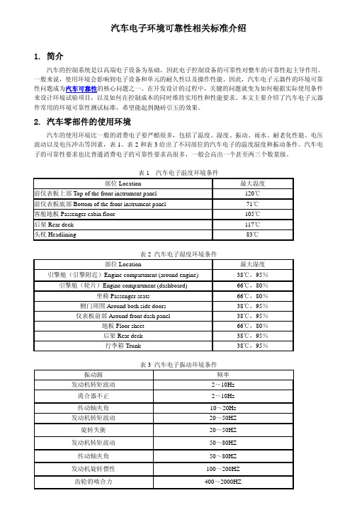
2. 汽车零部件的使用环境汽车的使用环境比一般的消费电子要严酷很多,包括了温度、湿度、振动、雨水、耐老化性能、电压波动以及电压冲击等因素,表1、表2和表3给出了不同部位的汽车电子的温度湿度和振动条件。
汽车电子的可靠性要求也比普通消费电子的可靠性要求高很多,一般会高出一个甚至两三个数量级。
表1 汽车电子温度环境条件部位Location 最大温度前仪表板上部Top of the front instrument panel 120℃前仪表板底部Bottom of the front instrument panel 71℃客舱地板Passenger cabin floor 105℃后架Rear deck 117℃头枕Headlining 83℃表2 汽车电子湿度环境条件部位Location 最大湿度引擎舱(引擎附近)Engine compartment (around engine) 38℃,95%引擎舱(轮片)Engine compartment (dashboard) 66℃,80%坐椅Passenger seats 66℃,80%侧门周围Around both side doors 38℃,95%仪表板前部Around front dash panel 38℃,95%地板Floor sheet 66℃,80%后架Rear deck 38℃,95%行李箱Trunk 38℃,95%表3 汽车电子振动环境条件振动源频率发动机转矩波动2~10Hz离合器不正2~10Hz传动轴夹角 10~20Hz发动机转矩波动 20~50HZ旋转失衡 20~50HZ发动机转矩波动 50~80HZ传动轴夹角 50~80HZ发动机旋转惯性 100~200HZ齿轮的啮合力 400~2000HZ3. 国际通用测试标准 3.1 AEC 系列标准上个世纪九十年代,克莱斯勒、福特和通用汽车为建立一套通用的零件资质及质量系统标准而设立了汽车电子委员会(AEC),AEC 建立了质量控制的标准。
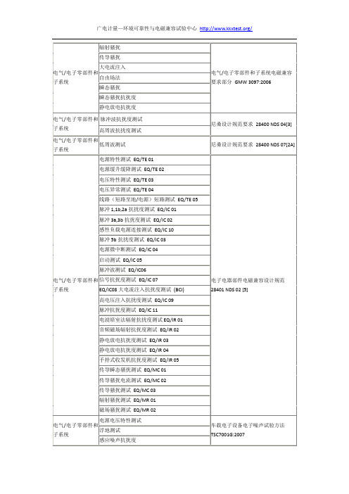
通用日产大众丰田汽车电子电磁兼容标准与项目
静电放电抗扰度测试EQ/IR03
静电放电抗扰度测试EQ/IR04
手持式收发机抗扰度测试EQ/IR05
传导瞬态骚扰测试EQ/MC01
传导骚扰电流测试EQ/MC02
传导骚扰测试EQ/MC03
辐射骚扰测试EQ/MR01
磁场骚扰测试EQ/MR02
电气/电子零部件和子系统
电源电压特性测试
电气/电子零部件和子系统
辐射骚扰
电气/电子零部件和子系统电磁兼容要求部分GMW3097:2006
传导骚扰
大电流注入
自由场法
瞬态骚扰
瞬态骚扰抗扰度
静电放电抗扰度
电气/电子零部件和子系统
脉冲波抗扰度测试
尼桑设计规范要求28400 NDS 04[3]
高周波抗扰度测试
电气/电子零部件和子系统
低周波测试
尼桑设计规范要求28400 NDS 07[2A]
反极性测试
过压测试
电源微中断测试
电压跌落恢复测试
叠加正弦波电压测试
叠加脉冲波电压测试
间断性内部短接电源/地测试
连续短路至电源/地测试
内部地短路电源测试
单线短时开路测试
多路间断开路测试
接地偏移测试
电源偏移测试
叠加数字波电压测试
过载测试
过载保险丝保护测试
绝缘电压测试
电气/电子零部件和子系统
E-01长时间过电压
对需要获得认可的车载零部件的电磁辐射骚扰测试方法TSC7026G:2008
电气/电子零部件和子系统
辐射骚扰
汽车电子零部件电磁干扰抑制测试方法TSC7508G:2008
电气/电子零部件和子系统
传导骚扰-电压法
德国大众 吨以下汽车电气和电子部件试验标准

共 94 页第1页LV 1243.5吨以下汽车电气和电子部件试验项目、试验条件和试验要求目录页适用范围第一部分:电气要求1 参考标准2 通用部分2.1 概念和定义2.2 扫描率和测量值分辨率2.3 工作电压范围2.4 功能状态2.5 工作方式2.6 参数试验2.7 用漂移分析法不间断监控参数2.8 物理分析2.9 接口说明2.10 实施的限制条件3 试验选择3.1 试验选择表4 电气试验和要求4.1 E-01 长时间过电压4.2 E-02 瞬态过电压4.3 E-03 瞬态欠电压4.4 E-04 Jumpstart(跃变启动)4.5 E-05 Load Dump(甩负荷)4.6 E-06 叠加的交流电压4.7 E-07 供电电压缓慢下降和缓慢提升4.8 E-08 供电电压缓慢下降快速提升4.9 E-09 复位特性4.10 E-10 短时中断4.11 E-11 启动脉冲4.12 E-12 具有智能发电机调整装置的电压波动波形4.13 E-13 插脚中断4.14 E-14 插头中断4.15 E-15 极性变换4.16 E-16 接地偏移4.17 E-17 信号线路和负荷电路短路4.18 E-18 绝缘电阻4.19 E-19 静止电流4.20 E-20 击穿强度4.21 E-21 反馈4.22 E-22 过电流第二部分:环境要求5 通用部分5.1 参考标准5.2 概念和定义5.3 工作方式5.4 渗透温度5.5 参数试验5.6 用漂移分析法不间断监控参数5.7 物理分析6 使用特性曲线6.1 寿命设计6.2 温度集中试验7 试验选择7.1 试验选择表7.2 试验流程图8 机械试验和要求8.1 M-01 自由落体试验8.2 M-02 碎石冲击试验8.3 M-03 防灰尘试验8.4 M-04 振动试验8.5 M-05 机械冲击试验8.6 M-06 机械持续冲击试验9 气候试验和要求9.1 K-01 高温 / 低温存放9.2 K-02 梯度温度试验9.3 K-03 低温工作9.4 K-04 再次油漆温度9.5 K-05 温度冲击试验(部件)9.6 K-06 盐雾喷射试验,在舱外工作情况下9.7 K-07 盐雾喷射试验,在舱内工作情况下9.8 K-08 湿热循环试验9.9 K-09 湿热循环试验(附霜冻)9.10 K-10 防水保护— IPX0至IPX6X9.11 K-11 高压射流清洗 / 蒸汽射流清洗9.12 K-12 有浪涌水的温度冲击试验9.13 K-13 浸入式温度冲击试验9.14 K-14 恒定湿热试验9.15 K-15 与部件组一起的凝露试验9.16 K-16 温度冲击试验(无外壳)9.17 K-17 阳光辐射试验9.18 K-18 有害气体试验10 化学试验和要求11 寿命试验11.1 L-01 机械 / 液压耐久寿命试验11.2 L-02 高温耐久寿命试验11.3 L-03 温度交变耐久寿命试验12 附录12.1 试验流程图12.2 各种安装范围的典型温度集中试验12.3 高温耐久寿命试验计算模型12.4 温度交变耐久寿命试验计算模型12.5 恒定湿热试验计算模型—锐度212.6 凝露试验、试验箱程序设计和曲线12.7 汇总适用范围本标准是对3.5吨以下汽车使用的电气、电子、机械电子部件和系统试验项目、试验条件和试验要求的规定。
元件检验规范
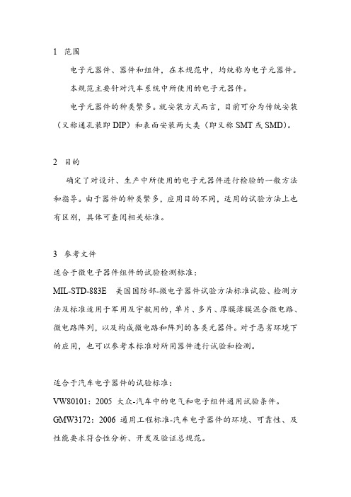
1范围电子元器件、器件和组件,在本规范中,均统称为电子元器件。
本规范主要针对汽车系统中所使用的电子元器件。
电子元器件的种类繁多。
就安装方式而言,目前可分为传统安装(又称通孔装即DIP)和表面安装两大类(即又称SMT或SMD)。
2目的确定了对设计、生产中所使用的电子元器件进行检验的一般方法和指导。
由于器件的种类繁多,应用目的不同,适用的试验方法上也有区别,具体可查阅相关标准。
3参考文件适合于微电子器件组件的试验检测标准:MIL-STD-883E美国国防部-微电子器件试验方法标准试验、检测方法及标准适用于军用及宇航用的,单片、多片、厚膜薄膜混合微电路、微电路阵列,以及构成微电路和阵列的各类元器件。
对于恶劣环境下的应用,也可以参考本标准对所用器件进行试验和检测。
适合于汽车电子器件的试验标准:VW80101:2005大众-汽车中的电气和电子组件通用试验条件。
GMW3172:2006通用工程标准-汽车电子器件的环境、可靠性、及性能要求符合性分析、开发及验证总规范。
MES PW67600:1995马自达工程标准-汽车器件试验标准。
主要检验标准有:GB/T5729—94《电子设备固定电阻器第一部分:总规范》;GB/T2693-2001《电子设备用固定电容器第1部分:总规范》;GB/T8554—1998《变压器和电感器测量方法及试验程序》;GB/T4023-1997《半导体器件分立器件和集成电路第2部分:整流二级管》;GB/T6571-1995《半导体器件分立器件第3部分:信号(包括开关)和调整二级管》;GB/T4587-94《半导体器件分立器件和集成电路第7部分:双极型晶体管》;GB/T4586-94《半导体器件分立器件第8部分:场效应晶体管》;GB/T15651.2-2003《半导体器件分立器件和集成电路第5-2部分:光电子器件基本额定值和特性》;GB/T15291-94《半导体器件第6部分晶闸管》;GB3442-86《半导体集成电路运算(电压)放大器测试方法的基本原理》;GB/T6798-1996《半导体集成电路电压比较器测试方法的基本原理》;GB/T4377-1996《半导体集成电路电压调整器测试方法的基本原理》;GB3439-82《半导体集成电路TTL电路测试方法的基本原理》;GB3834-83《半导体集成电路CMOS电路测试方法的基本原理》;GB/T14028-92《半导体集成电路模拟开关测试方法的基本原理》;GB3443-82《半导体集成电路MOS随机存储器测试方法的基本原理》;YD/T731-2002《通信用高频开关整流器》;YD/T1019-2001《数字通信用实心聚烯烃绝缘水平对绞电缆》;GJB128A-97《半导体分立器件试验方法》;GJB150-86《军用设备环境试验方法》;GJB360A-96《电子及电气元件试验方法》;GJB548A-96《微电子器件试验方法和程序》等。
德国大众3.5吨以下汽车电气和电子部件试验标准
VW 80101:1987-06,1988-08,1992-01,1993-04,1994-05,1995-06, 1998-01,1999-06,2000-09,2001-04,2003-05,2004-07, 2005-06,2006-10,2009-03
更改情况
相对于 VW 801 01:2009-03 版本而言,已做如下的更改:
表 6:标准允差定义
2.1.6 标准值
如果没有另外规定的话,适用表 7 的标准值。
室温 空气湿度 试验温度 标称电压 工作电压(用于试验)
TRT=23℃±5℃ Frel=45%-75%RH T Prüf=TRT UN=12V UB=14V
表 7:标准值定义
2.2 扫描频率和测量值分辨率
测量系统的扫描频率抑或带宽必须与各种试验匹配。必须记录所有带最大值(峰值)的测 量值。
存储器功能必须在任何情况下始终保持在 A 功能状态下。必须随时保证非易失存储器的 完整性(不是及时性)。
必须在部件设计任务书中说明功能状态的时间流程。
必须与委托方协调和规定允许的故障存储器项目。
2.4.1 功能状态 A
试件在加载试验参数期间和之后必须满足预先规定的所有功能。
说明:在与设计功率有偏差时(功能受到高温或者低温限制),试件亦必须达到低于抑或 高于工作电压情况下的功能状态 A,如果工作电压在部件设计任务书中说明是允许的话 (Derating)。
共 94 页 第 4 页
VW80000:2009-10
12 12.1 12.2 12.3 12.4 12.5 12.6 12.7
附录 试验流程图 各种安装范围的典型温度集中试验 高温耐久寿命试验计算模型 温度交变耐久寿命试验计算模型 恒定湿热试验计算模型 — 锐度 2 凝露试验、试验箱程序设计和曲线 汇总
VW80101_EN_2005-06-01
Confidential. All rights reserved. No part of this document may be transmitted or reproduced without prior permission of a Standards Department of the Volkswagen Group.Parties to a contract can only obtain this standard via the B2B supplier platform “”.© VOLKSWAGEN AGF o r m F E 41 - 01.05T h e E n g l i s h t r a n s l a t i o n i s b e l i e v e d t o b e a c c u r a t e .I n c a s e o f d i s c r e p a n c i e s t h e G e r m a n v e r s i o n s h a l l g o v e r n .Page 2VW 801 01: 2005-065.2Temperature cycle tests (32)5.3Multi-stage temperature test (35)5.4Resistance to open air weathering (35)5.5Resistance to environmental factors (35)5.6Thermal shock (37)6Chemical requirements (40)6.1Resistance to chemical agents (40)6.2Engine cleaning (test IP X9K) (41)7Endurance testing (41)7.1Endurance testing of electrical and electronic systems/components (41)7.2Endurance testing of electromechanical systems/components (44)7.3Component-specific endurance testing (46)8Table (47)9Referenced standards (48)ChangesThe following changes have been made as compared to Volkswagen standard VW 801 01,2004-07:─Changes as compared to the last issue are marked by a vertical bar on the side of the modified text block.─Table 1: Test sequence changed─Table 2: Relevant areas for requirements combined─Sentence "If the values in the Table are not sufficiently specified, the requirements have to be defined in the Performance Specifications." added.─Functional status C added─Section 3.2: Operating voltage dips added─Section 3.3: Rear feed added─Section 4.6: Pull-out strength: aim clearly defined─Effectiveness of the strain relief at the line outlet from the DUT is simulated.─Section 5.3: Multi-step temperature test added─Section 5.6: Thermal shock─The type to be applied is to be defined in the Performance Specifications.─Section 7: Endurance testingSections restructured as follows:Section 7.1: Endurance testing of electrical and electronic systems/componentsSection 7.2: Endurance testing of electromechanical systems/componentsSection 7.2.1: Endurance testing with temperature cycle as a variable influencing service life Section 7.2.2: Endurance testing with load cycles as a variable influencing service life added Section 7.3: Component-specific endurance testing─Table 25: see Table 1, test sequence changedPrevious issues1987-06; 1988-08; 1992-01; 1993-04; 1994-05; 1995-06; 1998-01; 1999-06; 2000-09; 2001-04; 2003-05; 2004-07Page 3VW 801 01: 2005-061 ScopeVolkswagen standard VW 801 01 specifies general test conditions for electrical, electromechanical and electronic components/systems in vehicles.When referring to this standard in component-specific Technical Supply Specifications, drawings and Performance Specifications, Table 25 (Section 8) shall apply and be supplemented with the appropriate specifications in consultation with the responsible Volkswagen Group engineering departments.2 General requirementsThe requirements apply to the entire operating voltage and temperature range.The functions and test conditions required for the respective test shall be permanently monitored and documented (at least temperature and supply voltage as well as switching performance, voltage drops, load currents, closed-circuit current and bus messages including timing and content, etc., where applicable).If test severity is not indicated, the standard requirements shall apply.Requirements called out in drawings and Performance Specifications shall have precedence over component-specific Technical Supply Specifications.Requirements specified in component-specific Technical Supply Specifications take precedence over VW 801 01.Requirements called out in drawings, Performance Specifications and component-specific Technical Supply Specifications refer on principle to conditionedcomponents/systems.2.1 Specifications and test sequenceSee Table 1.Table 1 – Tests according to VW 801 01The test sequence must be followed.Designation Specifications from VW 801 01 Operating temperature see Section 2.3Aging temperature see Section 2.3Operating voltage see Section 3.1Test designation Specifications for tests acc. toVW 801 01 Each component and each DUT must meet all requirements in the following test sequence. Conditioning (aging in mechanically circulated air,without load) see Section 5.1.1Operation at low temperatures see Section 5.1.2Operation at high temperatures see Section 5.1.3Temperature cycle with specified rate of change see Section 5.2.1Insulation strength see Section 3.16Insulation resistance see Section 3.17Endurance shock test for systems/componentsin doors and lids see Section 4.2.1Mechanical shock test for systems/componentson the body see Section 4.2.2Fatigue limit see Section 4.1Endurance test see Section 7Page 4VW 801 01: 2005-06After conditioning (aging in mechanically circulated air without load), the following tests may be performed at the same time.Operating voltage dips See Section 3.2Rear feed see Section 3.3Function during undervoltage and overvoltage see Section 3.4Voltage level: HIGH/LOW status assignment see Section 3.4Operating current see Section 3.6Closed-circuit current consumption see Section 3.7Reverse polarity protection see Section 3.8Overcurrent resistancesee Section 3.9Overvoltage resistance during long-term operation see Section 3.10 Overvoltage resistance during short-termoperation see Section 3.11 Superimposed alternating voltage see Section 3.12Slow lowering and increasing of the supplyvoltage see Section 3.13Reset behavior at voltage dip see Section 3.14Short-circuit protection see Section 3.15 Interruptions see Section 3.18Voltage drops see Section 3.19Short-distance interference suppression acc. toTL 965 See Section 3.20.2Conducted interference acc. to TL 820 66 See Section 3.20.1.Radiated interference acc. to TL 821 66 See Section 3.20.3.EMC on sensor lines acc. to TL 823 66 see Section 3.20.1.3Immunity to electrostatic discharges acc. toTL 824 66 see Section 3.20.4Drop test see Section 4.3Crimp and plug connections see Section 4.4Push-on connection on electric and electroniccomponents in vehicles see Section 4.5Pull-out strength see Section 4.6Thermal shock test see Section 5.2.2Multi-stage temperature test see Section 5.3Resistance to open air weathering see Section 5.4Sealing against dust and spray water acc. toDIN 40050-9 see Section 5.5.1Moist heat, cyclic see Section 5.5.2Salt spray fog see Section 5.5.3Thermal shock see Section 5.6Resistance to chemical agents see Section 6.1Engine cleaning (test IP X9K) see Section 6.22.2 Definitions2.2.1 TermsSystem Functionally combined components, e.g. ABS system, ESP system Component Part of a functionally combined system, e.g. actuator, sensor, control unit DUT The system or component to be tested (device under test)Functions Contains system-specific and diagnostic functionsPage 5VW 801 01: 2005-062.2.2 AbbreviationsI N Nominal currentT NH The post-heating temperature is the maximum ambient temperature occurring in the relevant area for requirement (see Table 2) after vehicle cut-off.T oLThe maximum storage temperature is the highest temperature which ispermissible for storage or transportation of the DUT. It comprises temperatures during paint drying and heat built-up in the engine compartment. The DUT is not operated.T RT Room temperature (+23 ± 5) °C ; if not otherwise sp ecified this is the test temperatureT uB , T oBThe minimum / maximum operating temperature is the lowest / highest ambient temperature at which the DUT may be continuously operated. Self-heating is not taken into account.T uL The minimum storage temperature is the lowest temperature which is permissible for storage or transportation of the DUT. The DUT is not operated.U Bmax Maximum operating voltage at which the DUT can be continuously operated.U Bmin Minimum operating voltage at which the DUT can be operated. U N Nominal voltageU PA Test voltage at running engine U PB Test voltage at battery operationU PCTest voltage for reverse-polarity battery connection at external start2.3 Relevant areas for requirements and types of requirement for vehicles 3 Motoranbau 4 Wasserkasten9 Innenraum Dach 5 Schalttafel, Mittelkonsole 11 Dach und Heckbereich,Anbauteile außen,Front- und HeckdeckelFigure 1 – Relevant areas on vehicle for requirements5 Dashboard, center console4 Plenum panel 3 Engine-mounted parts,9 Passengercompartment roof11 Roof and rear area, exterior add-on parts, engine hood and trunk lid/tailgatePage 6VW 801 01: 2005-06Page 7VW 801 01: 2005-062.4 Material requirementsAll materials, lubricants and surface coating materials shall comply with the current edition of the Hazardous Substances Ordinance, as well as with the Environmental Standard for Vehicles according to VW 911 00 and with the emission behavior as stated in VW 501 80.2.5 Operating typesThe following operating types are distinguished:2.5.1 Operating type 1The DUT is not electrically operated.─Operating type 1.1 No lines are connected to the DUT.─Operating type 1.2 All lines are connected according to vehicle installation, but novoltage is applied.2.5.2 Operating type 2The DUT is electrically operated with the supply voltage U PB (battery voltage) as in a cut-off vehicle (engine OFF).All system components (e.g. sensors, actuators) and lines are connected to the DUT.─Operating type 2.1 System/component functions are not activated (e.g. sleepmode).─Operating type 2.2 Systems/components with function and activation in normaloperating mode.2.5.3 Operating type 3The DUT is operated with the supply voltage U PA (engine/alternator running).All system components (e.g. sensors, actuators) and lines are connected to the DUT.─Operating type 3.1 System/component functions are not activated.─Operating type 3.2 Systems/components with function and activation in normaloperating mode.2.5.4 Laboratory setup operating typeSame as operating type 3.2, but test voltage and electrical load according to the respective test. 2.6 Functional statusesThis Section describes the functional status of the DUT during and after the test.The functional status of the DUT is to be specified for each test. Additional requirements are to be defined and documented in the Performance Specifications.Page 8VW 801 01: 2005-062.6.1 Functional status AAll functions of the DUT perform as specified during and after exposure to the test parameters. If diagnostic control units are used, no error log entry shall occur.2.6.2 Functional status BAll functions of the DUT perform as specified during exposure to the test parameters; however, one or more of them can go beyond the given tolerance. All functions return to normal operation after the end of test parameter exposure. Memory functions shall perform according to functional status A.2.6.3 Functional status COne or more functions of the DUT do not perform as specified during exposure to the test parameters but return automatically to normal operation after the end of exposure.Malfunctioning is not permissible.2.6.4 Functional status DOne or more functions of the DUT do not perform as specified during exposure to the test parameters; however, after resetting or a simple technical measure (e.g. exchanging a defective fuse) the DUT returns to normal operation after the end of exposure.2.6.5 Functional status EOne or more functions of the DUT do not perform as specified during and after exposure to the test parameters; after the end of exposure the DUT has to be repaired or replaced.2.7 General test conditionsA minimum of 6 DUT are to be tested. For increased requirements at least 10 DUT are to be tested.All tests are performed using DUT that have already been conditioned (conditioning see Section 5.1.1).If tolerances are not specified for temperatures, a tolerance of ± 2 °C shall apply.Temperature measuring points according to DIN 50011-11 and DIN 50011-12.Unless otherwise specified, all testing is performed at room temperature T RT and a relative air humidity of 25 to 75 %.Test voltages shall be in accordance with Table 3. Other test voltages are only permissible after consultation with the responsible Volkswagen Group engineering departments. The test voltages shall be documented in the test report.Table 3 – Test voltagesTest voltage 1) 12 V systems(V) 24 V systems(V)U PA14 ± 0.1 28 ± 0.2U PB12 ± 0.1 24 ± 0.2 1) Test voltage applied to the DUTPage 9VW 801 01: 2005-06 3 Electrical requirements3.1 Operating voltagesFor operating voltages see Table 4.Table 4 – Voltages and notes for applicationNominal voltageU N 1)(V)Operating voltageU Bmin U Bmax 1)(V) (V)Notes for application12 6.0 15 for functions that shall retain their performance during starting12 9.0 15 for functions that shall retain their performance with the engine cut off12 10.8 15 for functions that shall retain their performance during engine operation24 above values eachmultiplied by 2groups as with nominal voltage 12 V1) Definitions acc. to DIN 72251NOTE: Operating voltage applied to the DUT.Ability to function in the network for network DUT shall be ensured according to voltage specifications from network Performance Specifications.3.2 Operating voltage dipsAimThis test simulates fast dips (ramps) of the operating voltage that might occur.TestThe voltage curve represented in Figure 2 shall be tested on DUT which receive their supply voltage via terminal 30 or terminal 15.The voltage curve represented in Figure 3 shall be tested on DUT which receive their supply voltage via terminal 75.For specifications of voltage values, time curve and number of test cycles see Table 5.All voltage curves specified in Table 5 are to be tested.Page 10VW 801 01: 2005-06Figure 2 – Voltage curve for DUT with voltage supply via terminal 30 or terminal 15Figure 3 – Voltage curve for DUT with voltage supply via terminal 75Table 5 – Levels / voltages / durations of the voltage curveVoltagecurve no.1 2 3 4 5 6 7 8Typical voltage curve for engaging startermotors StandardstartingvoltagepulseSharpstartingvoltagepulseMinimumoperatingvoltage ofpowerconsumingdevicesrelevantduringenginestart-upRamp 1Ramp 2Ramp 3ToleranceU B12 V 12 V 12 V 12 V 12 V 12 V 12 V 12 VU S 5 V 3 V 4.5 V 3 V 6 V 3 V 3 V 3 VU A 6.5 V 5 V 6.5 V 5 V 6.5 V 3 V 3 V 3 VU R0 V 0 V 2 V 2 V 2 V 0 V 0 V 0 V+0.2 Vt r≤ 5 ms ≤ 5 ms ≤ 5 ms ≤ 5 ms ≤ 5 ms ≤ 5 ms ≤ 5 ms ≤ 5 mst615 ms 15 ms 15 ms 15 ms 15 ms 15 ms 15 ms 15 mst750 ms50 ms 50 ms 50 ms 50 ms 50 ms 50 ms 50 mst8 2 s 1 s 10 s 1 s 10 s 100 ms 1 s 10 st f100 ms 100 ms 100 ms 100 ms 100 ms 100 ms 1 s 10 s± 10 %f 2 Hz 2 Hz 2 Hz 2 Hz 2 Hz 2 Hz 2 Hz 2 Hz ± 10 % Test cycles 10 10 10 10 10 10 10 10Intervalbetweencycles1 s –2 s 1 s -2 s 1 s – 2 s 1 s – 2 s 1 s – 2 s 1 s – 2 s 1 s – 2 s 1 s – 2 s ± 10 %RequirementsSee Table 6.Table 6 – Functional statusesVoltage curveno.1 2 3 4 5 6 7 8Operatingvoltage (V)NoteU min.U max.Functional statuses6 15 A 1 B 1 A 1 B 1 A 1 C 1 C C Power consuming devices relevant during engine start-up9 15 C 1 C 1 C 1 C 1 C 1 C 1 C C Standard10.8 15 C 1 C 1 C 1 C 1 C 1 C 1 C C Blanked-out during start-up1) no error log entries, no false diagnoses (e.g. warning information)3.3 Rear feedRear feed on terminal 15 is permissible up to a maximum voltage level of 1.0 V only.NOTE: Capacitive rear feedDischarge currents due to protective capacitances are no rear feed currents.Capacitances displaying a discharge curve of tau ≥ 10 ms when disconnecting shall be decoupled from the terminal line by means of diodes.3.4 Voltage level: Assignment of HIGH/LOW statusFor DUT not containing a defined interface the voltage levels are assigned to the input states as follows:HIGH detection: U ≥ U Bmin -2 VLOW detection: U ≤ 2 VThe transition from LOW to HIGH and vice versa must only take place if the voltage exceeds the levels or falls below the levels defined here.The following applies to all devices using CAN/MOST communication:Voltage levels when connected to terminal 15.HIGH detection: U ≥ 4 VLOW detection: U ≤ 2 V3.5 Function during undervoltage and overvoltageWhen detecting overvoltage or undervoltage, the DUT changes into secure state, i.e. no malfunction shall appear. All functions of the DUT automatically return to normal operation after returning into the operating voltage range.Functional restrictions shall be specified in the drawing or in the Performance Specifications.All devices relevant for engine startVoltage range15.5 to 17 VFunctional status Afor t < 1 sError log entry"overvoltage" acc. toVW 801 14Suppress all followingerror log entries Assuringoperatingvoltage dipsFigure 4 – Voltage definitions of network systems with a nominal voltage of 12 VA hysteresis of ≤0.5 V is permissible in the transition from undervoltage or overvoltage to the operating voltage range.The following applies to all control units relevant during engine start-up which have to be operable between 6 and 26 V: No error log entries due to other control units non-operable in the overvoltage and undervoltage range.NOTE 1: Undervoltage range: Functions that shall retain their performance during starting are to be defined in the Performance Specifications.NOTE 2: Overvoltage range: Functions that shall retain their performance during starting (e.g. external start simulation) are to be defined in the Performance Specifications.NOTE 3: For directly connected bulbs, the following requirement does not apply: “Functional statusA for t < 1 s in the voltage range from 15.5 to 17 V”.3.6 Operating currentThe current change rate must be ≤ 20 A/s for DUT with a power draw ≥ 350 W. Otherwise, release by the responsible Volkswagen Group engineering department is required.Operating type 3.23.7 Closed-circuit current consumption and closed-circuit charge consumptionClosed-circuit charge consumption is calculated as an integral of current consumption from the time of disconnection of terminal 15 extrapolated until 50 days after terminal 15 OFF. In this context, for all conceivable at-rest conditions of the vehicle, the highest possible closed-circuit charge consumption of the DUT is to be considered. The closed-circuit current equivalent is the current that results from the closed-circuit charge consumption divided by 50 days. See Figure 5.Figure 5 – Closed-circuit charge consumptionThe closed-circuit current consumption target for any DUT shall be 0 mA on principle. In the rest phase, a closed-circuit current of < 0.1 mA applies to DUT which have to be operated after disconnection of terminal 15. The closed-circuit charge consumption per DUT must not exceed 0.12 Ah within 50 days down-time. This charge consumption also applies to the necessary post-operation after disconnection of terminal 15.Otherwise, release by the Volkswagen Group engineering department responsible for closed-circuit current management is required. Operating type 2.13.8Reverse-polarity protectionAimThe resistance of the DUT against reverse-polarity battery connection at external start is simulated. This test is not applicable to the following components:─Alternators─Relays with fixed diodes, without external reverse-polarity protectionTestThe DUT is connected in the same way as it is in the vehicle with regard to fuse protection. A test voltage with reversed polarity is applied to all voltage inputs as well as all other terminals which are connected to the supply voltage. The outputs must not be activated.OFFOperating type Laboratory setupTest duration (60 ± 6) sTest voltage (see Table 6) according to the following applications:Case 1:Application with non-protected alternator.Test voltage = U PCCase 2:Application with protected alternator.Test voltage = U PATable 7 – Test voltages for reverse-polarity protectionNominal voltage(V) U PA(V)U PC(V)12 14 ± 0.1 4 ± 0.1RequirementFunctional status D. Replacement of defective fuses is permissible.3.9 Overcurrent resistance3.9.1 Mechanical switches and contactsAimThe overcurrent protection of mechanical switches and contacts is simulated.Test (for mechanical switches and contacts only)Operating type Laboratory setupLoad holding time 10 minLoad at I N≤ 10 A 3 x I NLoad at I N > 10 A 2 x I N, but min. 30 A and max. 150 A(Switch "ON" and "OFF" once under load.)Each contact must be tested individually in the case of multiple-contact relays and multiple-contact switches.RequirementFunctional status A.3.9.2 Electronic outputsAimThe overcurrent protection of electronic outputs is simulated.TestOperating type Laboratory setupLoad holding time 30 minCurrent load Current as required in Performance SpecificationsRequirementAll electronic outputs must be protected against overcurrent as required in Performance Specifications. Functional status C.3.10 Overvoltage resistance during long-term operationAimA defective voltage regulator on the alternator is simulated.TestOperating type Laboratory setupTemperature T = (T oB -20 °C)Test voltage 17 V –0.2 VTest duration 60 minTest voltage application on all voltage inputs.RequirementFunctional status A for all functions necessary for driving operation.At least functional status C for all remaining functions.3.11 Overvoltage resistance during short-term operationAimAn external start with increased voltage (jump-start) is simulated.TestOperating type Laboratory setupTest voltage 26 V –0.2 VTest duration 60 sTest voltage application on all voltage inputs.RequirementFunctional status A for all functions necessary for starting the vehicle.At least functional status C for all remaining functions.3.12 Superimposed alternating voltageAimAn alternating voltage superimposed on the operating voltage is simulated. TestOperating type Laboratory setupTest voltage 13 VAmplitude of the superimposedalternating voltage (sinusoidal) U = 1 VInternal resistance ofvoltage source ≤ 100 mΩFrequency range 50 Hz to 20 kHzType of wobble Linear triangleWobble duration 2 minTest duration 10 minRequirementFunctional status A.3.13 Slow lowering and increasing of the supply voltageAimA slow discharging and charging of the battery is simulated.TestOperating type Laboratory setupTest voltage application on all voltage inputs.Supply voltage decrease from U Bmax to 0 V.Supply voltage increase from 0 V to U Bmax.Voltage change (0.5 ± 0.1) V per minuteRequirementFunctional status A, within the operating voltage range.Functional status C, outside the operating voltage range.3.14 Reset behavior at voltage dipAimThe reset behavior of the DUT is simulated at different voltage dips. This test applies to DUT with reset function (normally DUT with a microcontroller).TestOperating type Laboratory setupTest procedure for ≥ 10 s Set U BminCycle for 5 s Lower the operating voltage U Bmin by 0.5 Vfor ≥ 10 s Set U Bmin and test the function of the DUTThe voltage is lowered by a further 0.5 V in each cycle (see Figure 6).The test comes to an end as soon as the voltage reaches ≤ 0.5 V. The voltage change takes place within 100 ms.U Bmin Figure 6 – Voltage curve for U Bmin = 9 V 1RequirementFunctional status A, within the operating voltage range. Functional status C, outside the operating voltage range. 3.15Short-circuit protectionAimShort circuits on inputs and outputs are simulated.The inputs and outputs (without load circuit) shall be short-circuit-proof to U PA and ground. TestShort-circuit all inputs and outputs one after another against U PA and ground. This test is performed on activated and non-activated outputs. Operating type 3.2 Test duration 60 s for each short circuit NOTE: Only if operating voltage is applied.1This graphic was adopted from the original German document, and the numerical notation may therefore differ from the Englishpractice. A comma corresponds to a decimal point, and a period or a blank is used as the thousands separator.RequirementFunctional status C.3.16 Insulation strengthAimThe insulation strength of the DUT between components without galvanic connection, e.g. pins, relays, windings or cables is simulated.This test is only performed for DUT containing inductive components (e.g. motors, relays, coils). TestOperating type Laboratory setupTest temperature (35 ± 5)°CHumidity (50 ± 5) %Test voltage (rms voltage) 500 V AC, 50 HzTest duration 60 sApplication of test voltage─on terminals without galvanic connection.─between connection pins and conducting housing without galvanic connection.─between connection pins and an electrode around the housing if the housing is non-conducting.RequirementFunctional status C. Dielectric breakdown and electric arc are not permissible.3.17 Insulation resistanceAimThe insulation resistance between components without galvanic connection is determined.TestOperating type Laboratory setupTest temperature (35 ± 5)°CHumidity (50 ± 5) %Test voltage 100 V DC voltage for component spacing < 3.8 mm500 V DC voltage for component spacing > 3.8 mmTest duration 60 sApplication of test voltage─on terminals without galvanic connection.─between connection pins and conducting housing without galvanic connection.─between connection pins and an electrode around the housing if the housing is non-conducting.RequirementFunctional status C, insulation resistance > 10 MΩ3.18 InterruptionsAimA line interruption is simulated.TestOperating type 3.2Pin interruptionEach pin individually on each plug (remove and replace pin again)Interruption time 10 sPlug interruptionPlug by plug (remove and replace plug again) under all operating states (sequence optional) Interruption time 10 sRequirementFunctional status C.3.19 Voltage dropsAimThe maximum permissible voltage drops are tested.Relays in control units are to be tested corresponding to relay contacts.TestOperating type Laboratory setupRelay contactsVoltage drop ≤ 5 mV/A, but ≤ 100 mV absoluteTesting with nominal current According to drawing, Performance Specifications or TechnicalSupply SpecificationOperating current According to drawing, Performance Specifications or TechnicalSupply SpecificationSwitch contacts according to VW 801 02Electronic outputs According to drawing, Performance Specifications or TechnicalSupply SpecificationRequirementsThe permissible voltage drops shall neither be exceeded throughout the service life of the components nor during testing.3.20 Electromagnetic compatibility (EMC)3.20.1 Conducted interference3.20.1.1 Transient emission of supply linesRequirements according to TL 820 66, Performance Specifications or drawing.。
试验项目操作说明 大众标准
文档类型 产品类型 适用标准
TS 大众 VW8000:2009
1 适用范围及说明...................................................................................................................................................5 1.1 参考标准 ..........................................................................................................................................................5 1.2 缩写定义 ..........................................................................................................................................................5 1.3 工作模式 ..........................................................................................................................................................6 1.3.1 工作模式 I --- 试件未电气连接 .......................................................................................
汽车电气VW80101_091101_和电子部件一般试验条件_中文版

在对应的试验中所要求的功能和试验条件�要始终加以监控并编制成文件�至少要有温度、 供电电压�如果涉及的话�还有开关特性、电压降、负荷电流、静止电流、总线帧�包括 时间和内容�等等�。
如果试验没有说明严苛程度�就必须以标准要求为基础。
VW 80101 标准预先规定了各项试验要求有关温度、抗振动能力和密封性能方面的数 值。如根据安装情况而发生偏差�则应将这种不一致的情况编写在设计任务书上。
汽车电气和电子部件
一般试验条件
共 59 页 第 1 页
VW
80101
分类号�8MA00 关键词�部件、电气部件、电子部件、试验条件
以前版本
VW 80801�1987�06�1988�08�1992�01�1993�04�1995�06�1998�01� 1999�06�2000�06�2000�09�2001�04�2003�05�2004�07� 2005�06�2006�10�2009�03
共 59 页 第 2 页
页 3 3 4 5 6 9 9 10 11 11 11 12 12 15 17 17 18 19 20 20 21 21 22 23 24 25 26 26 27 27 27 37 38
VW 80101�2009-11
4.4 压接和插接 4.5 汽车中电气部件和电子部件的接插连接 4.6 导线抗拉强度 5 气候要求 5.1 恒定温度下的试验 5.2 交变温度下的试验 5.3 梯度温度试验 5.4 大气曝晒耐抗性 5.5 环境耐抗性 5.6 水温突变试验 6 化学要求 6.1 对化学品的耐抗性 7 耐久性试验 7.1 对电气和电子系统/部件的耐久性试验 7.2 对电子机械系统/部件的耐久性试验 7.3 针对零件特殊的耐久性试验 8 共同适用的资料
汽车车灯如何做可靠性测试

随着科学技术越来越精湛,灯作为汽车装饰的一部分,逐渐成为很多人重视的零部件。
而汽车车灯在面对空气中的氧气、水分、酸性物质等等腐蚀因素,再加上温度和湿度灯环境条件的变化,很容易缩短寿命,降低性能。
因此环境可靠性试验十分有必要。
一、常见汽车电子产品可靠性试验对于不同位置、不同用途的汽车电子产品,其环境可靠性测试要求也会不尽相同,当然对于不同品牌的汽车测试标准又会有一些差别。
大众VW80101-2009(汽车电气和电子部件一般试验条件)标准下,汽车电子产品对于环境要求做的试验也会有不同。
当然,汽车上电子产品成千上万,它们的可靠性直接决定了汽车运行安全,因此需要做的环境测试不计其数,而部分汽车车灯年复一年日复一日地暴露在室外,面对考验不容置疑。
二、汽车车灯检测覆盖范围-前雾灯、前照灯、前转向灯、前驻车灯、前示廓灯、前反射器;-后雾灯、后转向灯、后反射器、后示廓灯、后驻车灯、后位制动灯、高位制动灯、倒车灯、牌照灯;-侧标志灯、侧转向灯、侧反射器、侧驻车灯、日间行车灯、弯道照明灯、回复反光材料、反光标识;-三角警告牌、前照灯清洗器、低速车辆及重长车后标志牌、重长车回复反射器标志等。
三、汽车车灯环境可靠性试验方法国家相关文件规定,GB10485-2007《道路车辆外部照明和光信号装置环境耐久性》中规定汽车灯具需要进行的基本环境试验有:热循环试验——试样:前照灯或者前雾灯设备:多禾高低温试验箱(可编程)-循环次数:5次-每个循环时间:8h-温度转换速率:0.6℃/min~4.0℃/min-循环开始温度:20℃-低温:-30℃/至少2h-高温:60℃/至少2h-点灯:在A点开始点灯至B点关闭-电压:13.2V±0.1V热冲击试验——试样:前照灯或者前雾灯设备:直流稳压电源和水槽-温度:23℃±5℃-湿度:30%~60%-电压:13.2V±0.1V(或者28.0V±0.1V)-以最大功率点亮30分钟-点亮结束,配光镜整个外表面浸入23℃±5℃水中,5min热变形试验——试样:光信号装置设备:多禾高低温试验箱(可编程)-温度:45℃~48℃之间(对于后雾灯温度应为23℃±5℃)按照下面方式,以试验电压(13.5V±0.1V或28.0V±0.1V)点亮1h-拍照等、侧标志灯、前位灯、后位灯、后雾灯、驻车灯、昼间行驶灯和示廊灯应稳定点亮-制动灯和倒车灯应点亮5min,关闭5min-转向信号灯以闪烁方式点亮盐雾试验——试样:照明和光信号装置设备:盐雾试验箱-温度35℃±2℃-盐雾沉降率(1.0~2.0)mL/(h.80cm²)-氯化钠盐溶液浓度5%±0.1%,pH值(35℃时)6.5~7.2 -循环次数:10次-每个循环喷雾23h,干燥1h-结束后离子水清晰5min,并在自然对流条件下干燥。
大众实验要求VW80101 中
汽车中的电气和电子组件通用试验条件关键词:组件,电气组件,电子组件,试验条件目录1 适用范围2 概述2.1 规则和试验顺序2.2 定义2.3 汽车部件的要求范围和其对车辆的要求方式2.4 材料要求2.5 工作方式2.6 功能状态2.7 通用试验条件3 电气要求3.1 工作电压3.2 反馈3.3 电平:高-低端配置3.4 过压和电压不足下的功能3.5 静态电流记录3.6 工作电流3.7 防电极反接3.8 过流耐抗性3.9 长时过载耐抗性3.10 短时过载耐抗性3.11 叠加的交变电压3.12 供电电压的缓慢降低和升高3.13 电压中断情况下的复位性能3.14 短接耐抗性3.15 击穿耐抗性3.16 绝缘电阻3.17 断路3.18 电降压3.19 电磁兼容性(EMV)4 机械要求4.1 振动4.2 机械振动4.3 落体试验4.4 卡接和插接4.5 车辆中电气和电子组件的插接接头5 气候方面的要求5.1 恒定温度下的试验5.2 交变温度下的试验5.3 大气曝晒试验耐抗性5.4 环境耐抗性5.5 温度突变6 化学要求6.1 试剂耐抗性6.2 发动机清洁剂耐抗性7 耐久性试验7.1 零件耐久试验7.2 电气和电子系统/部件耐久性试验7.3 电气机械系统/组件耐久性试验8 表格9 参考资料更改:对VW 801 01:2003-05的版本作了如下更改:-章节2.3,车辆的要求范围和要求方式图1:第8部分增加了“中间隧道”。
-表格2要求范围和其要求方式防尘和防喷溅水密封性的要求中对于前部区域(内/外),发动机舱,发动机附件,水箱,底盘,车顶,前盖外板附件,变速器附件和已脱落进气管的保护方式改为IP 5K9K。
增加了章节:对于安全性重要的部件适用:防尘和防喷溅水密封性要在任务书中进行定义-如果表格2中的说明不足的话。
如果试件可以在水下直立,就使用防护方式IP 68(如门和盖罩,脚踏空间,水箱,被子架,抽屉内侧)。
VW2.8.1中文版

仅在图纸上有补充写了“回弹>…%” 的情况下要求。
DIN 53512
13
绝缘电阻,M∏,
>1000。仅在图纸上有补充写了“绝缘”的情况下要求。
DIN IEC 60167
14
自动涂油
3.13
-
-
-
仅在图纸上有补充写了“自动涂油”的情况下要 求。
15
腐蚀状况
允许级别 1 和级别 2。
VW 2.8.1
16
60±5 0 至+31) -4 至+1 -2 至+8
75±5 60±5 60±5 0 至+31) 0 至+31) 0 至+31) -4 至+1 -4 至+1 -4 至+5 -2 至+8 -2 至+8 -4 至+5
60±5 65±5
0 至+31) -
0至 +31) -
-
-
>6
>6
>6
>7
>6
>6
>81)
耐触介质 试验温度单位:℃ (误差要求见图纸) 试验介质
质量 识别 号 1
2
3 3.1 3.2 3.2.1
3.2.2 4 4.1 5
5.1 5.2
5.3 6 6.1
特性
热量分析,成分% PV 3927 和/或气体色谱法质谱 仪作为鉴定试验 密度单位:g/cm3, DIN EN ISO 1183-1 硬度按肖氏 A, DIN 53505 交货情况的最佳硬度 供货变动 热老化后,给出要求温度, DIN53508 在接触介质中放置后 重量变化百分比% 在接触介质中放置后 抗拉强度,单位:N/mm DIN 53504 在交货时的情况 热老化后,给出要求的温度, DIN 53508 在接触介质中放置后 断裂张力,%,DIN53504 在交货时的情况
一汽大众汽车电子电器验收标准
变更: 相对于 VW 80101:2006-10,发生如下变更: - 用“化学试剂”替代“试剂” - 表 2:修改保护程度规定 - 第 2.6 节,删除“温度测量位置根据……”。 - 第 3 节,修改表 4 和表 5 中的电压。 - 表 5 和表 6:增加热启动脉冲, - 更新图 2 - 第 3.4 节,修改“反馈” - 图 4 更新“电压定义大纲” - 第 3.8 节,补充反极保护 - 第 3.12 节:补充重叠交变电压的振幅 - 第 3.12 节:修改摇晃类型 - 图 8:修改标题 - 第 4.6 节:详细阐述目的 - 第 5.1.2 节:补充错误与遗漏条款 - 图 20-22:修改工作方式 - 补充及修改表 18 - 表 2:增加 VW 80101 至“保护程度规定”
汽-大众实验室13条重点介绍内容

一汽-大众实验室13条重点介绍内容1. 内饰颜色匹配整车颜色匹配是以标准色板为依据,采用仪器测量及目视评价相结合的方式,对零件颜色进行控制,并利用标准光源间提供的各种光源对整车内饰颜色的匹配进行评价,以使整车内饰颜色协调统一,从而在视觉上给顾客营造一种高贵、和谐的驾乘环境。
2. 整车电气网络诊断分析汽车进入了一个网络化的时代,一辆汽车就是一个局域网络单元,车辆的分析和诊断离不开自身的网络环境和与数据中心的信息交换, 通信手段使汽车电子技术得到了更好的应用,因此汽车中出现了越来越多的控制单元— ECU,这些ECU借助软件,按照规定的通信协议进行信息的共享,传输和诊断。
我们这个台架相当于一台多配置的汽车,可以对控制器,传感器和执行机构进行故障的分析和诊断,在网络环境中进行综合测试,例如防盗系统的匹配,元器件保护系统的释放,通信信号的采集和测量分析等.离开了这个网络环境对ECU的分析测试是无法实现的。
3. 非金属机械性能实验本房间的设备主要用于检测非金属材料的机械性能,共有19台设备。
所用的仪器绝大部分为进口,像万能试验机,硬度计,冲击试验机均为德国ZWICK公司制造,性能优良,与德国大众和奥迪公司所用设备一致。
机械性能为材料的基本性能,如硬度,拉伸强度,延伸率,冲击性能等,同时根据德国大众的标准,有些多层复合零件如仪表板,门板还要检验剥离力,橡胶材料检验再撕裂力,密封条要检验密封力等性能。
同时,还有一台试验机可实现在高低温下进行测试,及一台激光回弹仪用来测量密封条的压缩永久变形。
4. 非金属材料耐候性实验材料耐侯性实验是在实验室利用仪器模拟户外的光照、温度及湿度等条件对材料进行的加速老化试验。
通过人工模拟出干热及湿热的气候条件,分别对内饰件、外饰件进行实验,以快速评价各种非金属材料的耐候性能。
5. 非金属材料微量分析材料微量分析实验室现有热分析仪、色谱/质谱仪、裂解仪、红外光谱仪等国际先进的分析仪器。
- 1、下载文档前请自行甄别文档内容的完整性,平台不提供额外的编辑、内容补充、找答案等附加服务。
- 2、"仅部分预览"的文档,不可在线预览部分如存在完整性等问题,可反馈申请退款(可完整预览的文档不适用该条件!)。
- 3、如文档侵犯您的权益,请联系客服反馈,我们会尽快为您处理(人工客服工作时间:9:00-18:30)。
组件
具备逻辑功能的系统的零件,比如执行器,传感器,控制器
试件
待检验系统或者组件
4
2.2.2 缩写
IN
标定电流
TNH
余热温度即为车辆熄火后在要求范围所在的最高环境温度(参见表格2)。
TOL
存放温度上限为试件存放和运输过程中所允许的最高环境温度。它包括例如发动
机舱中油漆干燥和滞留热量。试件不予起动。
TRT TuB,ToB
2.6.1 功能状态A 试件在加载各项试验参数过程中和加载后满足规定中的所有功能。该状态要在具诊断能力的控 制器无任何故障存储记录。
2.6.2 功能状态B 试件在加载各项试验参数过程中和加载后满足规定中的所有功能。但可能有一项或多项功能在 规定的公差范围之外。结束加载试验参数以后试件重新满足所有规定中的所有功能。存储功能 必需保持在功能状态A。
IP 5K 0
s,u m,r,s,t e,f,g,I,j,q,s
a至q
IP 5K 0 IP 5K 0 IP 5K 4K
IP 5K 9K1)
f,g,i,q,s a至q a至q
IP 5K 9K IP 5K 9K1) IP 5K 9K1)
6
对于安全性重要的部件适用: 防尘和防喷溅水密封性要在任务书中进行定义-如果表格 2 中的说明不足的话。 如果试件可以在水下直立,就使用防护方式 IP 68(如门和盖罩,脚踏空间,水箱,被子架, 抽屉内侧)
2.5.2 工作方式2
试件采用蓄电池通电工作、车辆未开动(即为发动机不工作)
所有系统组件(比如传感器、执行器)和缆线全部接通。
工作方式1
系统/组件功能不予激活(比如睡眠模式)。
工作方式2
系统/组件发挥功能和操控规定的工作方式。
2.5.3 工作方式3
试件在工作电压UPA(发动机/发电机运转)下工作 所有系统组件(比如传感器、执行器)和缆线全部接通。
4.1.4
4.1.4 4.1.4 4.1.4
4.2.2
4.2.1 4.2.2 车门4.2.1 4.2.2
4.2.2 4.2.2 4.2.2
-40
70
-40
80
-40
70
-40
70
-40
95
-40
70
-40
70
12地盘
4.1.4
4.2.2
-40
70
13车顶、前盖, 后盖和外部附件 14变速器附件
4.1.4 4.1.2
UN
标定电压。
UPA
发动机运转情况下的试验电压。
UPB
蓄电池驱动时的试验电压。
UPC
外接起动情况下电极反接蓄电池的试验电压。
2.3 车辆的要求范围和要求方式 见图1和表格2
图1: 要求范围
5
要求方式 要求范围
La前部区域内侧 Lb前部区域内侧 2发动机舱
振动载荷按照章 机械振动按照章 工作温度范围℃
- 章节4.6 导线抗拉强度 目的补充:“出自试件”
- 章节5.4.1防尘和防飞溅水密封性 补充水温10℃±5℃ 补充试件温度和环境温度TOB 补充备注:试件的安装位置必需在图纸中给予定义。插头处不允许有空气流动。
- 章节5.4.3盐雾试验 添加了和DIN EN 60068-2-11的偏差:在没有盐雾情况下的温度TRT
见章节3.17 见章节3.4 见章节3.7 见章节3.2
见章节3.3
见章节3.5 见章节3.6 见章节3.13 见章节5.4.1 见章节5.4.2 见章节5.4.3 见章节6.1 见章节6.2 见章节 5.5 见章节5.2.2 见章节4.3 见章节5.3
2.2 定义
2.2.1 概念
系统
具备逻辑功能的组件集合,比如ABS系统,ESP系统
2.4 材料要求 各零件必需无缺陷。 塑料件必需可耐抗章节1.4中规定的存放温度上限和下限。 所有的材料、润滑材料和涂层材料必需符合危险材料规定,以及按VW91100的环境标准和按 VW50180的散发特性的最新版本。
2.5 工作方式 工作方式分为如下各种:
2.5.1 工作方式1 试件不进行通电起动。 工作方式1.1 缆线不与试件连接。 工作方式1.2 所有缆线依照车辆装配接好,但不加电压。
节
节
TuB
ToB
4.1.4 精度2
4.1.4
4.2.2 4.2.2
-40
1203)
-40
70
-40
1203)
3发动机附件
4.1.1
-40
140
4水箱
4.1.4
4.2.2
-40
70
5仪表板,副车架
6车门内板 7车门、侧围外板
4.1.4 精度2 4.1.4
4.1.4
8内舱地板,横隔 板和中间隧道 9内舱车顶 10行李舱 11车尾区域
2. 通用要求 各项要求适用于所有工作电压和工作温度范围。 在对应的试验中所要求的性能和试验条件要始终加以监控和记录(至少要有温度、供电电压, 如果相关的话还有整流特性,电压降,荷载电流,静态电流,总线增强帧包括周期和内容等等)。 如说明中未给出试验精确度,则以标准要求为准。
图纸要求和任务书中的说明优先于零件专用技术供货条件。 零件专门技术供货条件中的要求优先于 VW80101。 图纸要求、任务书中和零件专用的技术供货条件中的说明通常涉及的对象为传统的组件/体 系。
2.1 规则和试验顺序 在下列试验实验的进行中和结束后,所有零件/试件必需达到所要求的性能。要求适用于整个工 作电压和工作温度范围。需始终检验相关的功能要求。
需遵守试验顺序 名称
表格 1:试验按照 VW80101 引自 VW 801 01的说明
材料使用温度 工作电压 工作温度 存放温度 按照VW 801 01进行试验 试验名称
工作方式1
系统/组件功能不予激活。
工作方式2
系统/组件发挥功能和操控规定的工作方式。
2.5.4 试验时车身工作方式 与工作方式3.2相同,只是试验电压和电载荷要符合相应的试验。
2.6 功能状态 本章节描述试件在试验期间以及试验后的功能状态。 每个试验的试件的功能状态都要予以说明。附加的要求要在任务书中定义并做出文本记录。
汽车中的电气和电子组件 通用试验条件
关键词: 组件,电气组件,电子组件,试验条件
目录
1 适用范围 2 概述 2.1 规则和试验顺序 2.2 定义 2.3 汽车部件的要求范围和其对车辆的要求方式 2.4 材料要求 2.5 工作方式 2.6 功能状态 2.7 通用试验条件 3 电气要求 3.1 工作电压 3.2 反馈 3.3 电平:高-低端配置 3.4 过压和电压不足下的功能 3.5 静态电流记录 3.6 工作电流 3.7 防电极反接 3.8 过流耐抗性 3.9 长时过载耐抗性 3.10 短时过载耐抗性 3.11 叠加的交变电压 3.12 供电电压的缓慢降低和升高 3.13 电压中断情况下的复位性能 3.14 短接耐抗性 3.15 击穿耐抗性 3.16 绝缘电阻 3.17 断路 3.18 电降压 3.19 电磁兼容性(EMV) 4 机械要求 4.1 振动 4.2 机械振动 4.3 落体试验 4.4 卡接和插接 4.5 车辆中电气和电子组件的插接接头 5 气候方面的要求 5.1 恒定温度下的试验 5.2 交变温度下的试验 5.3 大气曝晒试验耐抗性
工作电流 静态电流 电压中断情况下的复位性能 防尘和防喷溅水密封性按DIN 40050-9 湿热循环 盐雾 试剂耐抗性 发动机清洁剂(检测 IP X9K) 温度突变 温度骤变试验 落体试验 气候交变耐抗性
见章节3.19.2 见章节 3.19.1 见章节3.19.3 见章节3.19.1.3 见章节3.19.4
TuL
ToL
40
130
90
40
140
40
140
40
90
40
90
40
100
40
90
40
90
40
105
40
90
40
90
40
90
40
90
40
140
40
140
环境耐抗性
盐雾 湿热环境 盐雾 湿热环境 盐雾 湿热环境 盐雾 湿热环境 湿热环境
湿热环境 盐雾 湿热环境 湿热环境
湿热环境 湿热环境 盐雾 湿热环境 盐雾 湿热环境 盐雾 湿热环境 盐雾 湿热环境 盐雾 湿热环境
3
变化速度恒定的温度交变
电降压 线束抗拉强度 过流耐抗性 过载耐抗性 长时 过载耐抗性 短时 叠加交变电压 供电电压的缓慢降低和升高 短接耐抗性 击穿耐抗性 绝缘电阻 车门内和卡入结构系统/组件的持续振动试验 车身上的系统/组件的机械振动试验 抗震强度 耐久试验 下列试验可在预处理后(无载通风存放)同时进行
极限值见存放温度 见章节 3.1 见章节2.3 见章节 2.3
按照VW 801 01 进行试验时的说明
每个零件,试件都要按照以下顺序进行所有的试验。 预处理(无载) 材料要求 卡接和插接 车辆中电气和电子组件上的接头 低温下工作 高温下工作
见章节5.1.1 见章节2.4 见章节t4.4 见章节t 4.5 见章节5.1.2 见章节5.1.3
4.2.2
-40
前/后盖 4.2.1
-40
70 1403)
15已脱落进气管 4.1.3
-40
1403)
1) 附件按照章节6.2的发动机清洁剂试验以及按照章节5.5的喷溅水试验 2) 如果任务书有要求的情况下,只用试剂c(蓄电池酸液) 3) 包括再加热周期的温度曲线符合图示12和表格15
存放温度范围℃
1
5.4 环境耐抗性 5.5 温度突变 6 化学要求 6.1 试剂耐抗性 6.2 发动机清洁剂耐抗性 7 耐久性试验 7.1 零件耐久试验 7.2 电气和电子系统/部件耐久性试验 7.3 电气机械系统/组件耐久性试验 8 表格 9 参考资料