马达驱动电路MX1508RX2产品手册_V1.1
摩尔克斯 MX150 封闭和非封闭接线器系统说明说明书
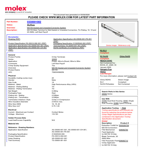
Blade Terminals, 20
AWG Wire
FA2 Pneumatic Feed 638082710
Crimp Applicator
for MX150 18 Grip
Blade Terminals, 20 AWG FA2 Mechanical 638082900 Feed Applicator for MX150 18 Grip Male Terminals, 18 AWG, 0.75mm² and 1.00mm² Wire FA2 Mechanical 638084100 Feed Applicator for MX150 Mat Seal/ Unsealed Blade Terminals, 16 AWG TXL Wire and 18 AWG GXL Wire FA2 Pneumatic Feed 638084110 Applicator for MX150 Mat Seal/Unsealed Blade Terminals, 16 AWG TXL Wire and 18 AWG GXL Wire Hand Crimp Tool, 638112400 14-16 AWG Hand Crimp Tool, 638112600 18-22 AWG Manual Extraction 638131500 Tool FineAdjust Applicator639040800 for SRC Connector using MX150 Receptacle Terminals, 0.75mm² wires
Documents: Drawing (PDF)
Product Specification PS-33012-002-001 (PDF) Application Specification AS-33000-001-001 (PDF) Application Specification AS-33000-001-CH-001 (PDF)
开发板初次使用指南

山东大学机器人电子强力驱动
打开 USB 驱动.EXE 可以看到如下画面,点击 INSTALL 即可安装(注意,此时请先不要连 接开发板与计算机)
打开检测程序,此时连接开发板与计算机,等待系统发现新硬件,让其自动安装驱动即可, 注意忽略数字认证警告。
如果安装成功既可看到 RoboElc 提示“成功打开 CH341 设备” 。注意一定要正确安装驱动, 否则无法下载程序。
绿色底板 板子跳线已经事先接插正确,当您将 USB 供电插上时,可以看到测试程序(流水灯、蜂鸣 器、数码管、DA 指示灯) 注意:8051 核心板上晶振跳线帽必须接插 以下为 AVR 核心板图片
待学习 AVR(开发板支持 ATMega16 等)时请将 8051 核心板拔下,插入 AVR 核心板,注 意方向朝上。 建议用户首先学习 8051,将内部资源等知识学习扎实再学习 AVR,我们不建议在基础知识 还没有打牢的情况下学习额外知识。 如果用户在学习好 8051 后,可以自己动手制作 STC12 系列增强型 51 核心板用于练习。
山东大学机器人电子强力驱动
螺丝螺母、跳线帽
双头 USB 线
串口延长线
10 根杜邦线
山东大学机器人电子强力驱动
底板视图(绿色)
底板视图(黑色)
软件方面:
(详见光盘) 说明: 1、首先安装 USB 驱动.EXE(USB 驱动程序) 2、然后连接 PC 与开发板,按照 USB 驱动提示操作即可 3、打开 RoboElcX 监控软件,使用该软件进行程序烧写 4、程序所有权归 WCH 公司所有 操作:
山东大学机器人电子强力驱动
RoboElc 51_AVR V1.1 开发板
初次使用指南
尊敬得用户您好!
功能详解图
Zenith MX150 MX250 自动转换开关网络卡 50P-2035 维护与操作手册说明书
—OPERATION AND MAINTENANCE MANUALZenith Modbus Network Card 50P-2035 For MX150/MX250 (MX Version 6.0+ Only)ABB Zenith disclaims any and all liability for use of third-party application software that will be used to control the Automatic Transfer Switches.PageOverview (01)LED Indicator (01)Installation (02)Installation on the Controller (02)Termination Resistor (02)Configuring a Modbus Network Card (02)Testing a Modbus Network (03)CDP Programmable Exercisers (03)CDT Exercisers (3)Operation (04)Setting System Time (04)Operation with In-Phase Monitor (04)Operation Under Battery Backup (04)Appendix A – Read Only Register List......................................................................................................................05-12 Appendix B – Read/Write Register List................................................................................................................13-14 Appendix C – Modbus Network Card. (15)Appendix D – Connections for Configuring and Testing the Modbus Card (16)Appendix E – RS485 Multi-Drop Connection (17)Appendix F – Installation of Modbus Card on Controller (18)Appendix G – Modbus Protocol Illustration......................................................................................................19-21 Appendix H – Configuring Controller for Modbus (MX150/250). (22)Bill of Materials (23)Components for the Modbus Option (ZNET250M) (23)Components for the Modbus Card Configuration (23)Troubleshooting (24)Testing a Modbus NetworkThe Modbus network can be tested using the compo-nents in the Modbus Configuration package (ABB Zenith Part # 50P-1124). Reference Appendix D for connections.1.If testing a network consisting of more than onecard, make sure that all of the cards are daisychained as shown in Appendix E. Verify that allModbus cards are in the run mode (jumper J4 onthe Modbus card must not be installed).Termination jumper (J6) is only installed on thelast card on the network daisy chain.2.Connect the RS232/485 converter (ABB Zenith Part# 50W-1208) to the PC that contains theConfiguration software (ABB Zenith Part # 50P-1111).A cable needs to be connected to the RS485 connectorof the Modbus card and the RS485 connector of theRS232/485 connector. Check to make sure that thepolarity connections are correct. (See Appendix D)3.Run the Configuration software on the PC.4.Press the TEST button and then verify that the settingsin the Communication Settings section match the settings of the Modbus network. If necessary, make changesto the settings and click the NEXT button.5.The software will now scan the network and displaythe serial number of all controllers, which have theModbus card attached. The user can select any ofthe listed serial numbers and execute a load test ona controller associated with the selected serial num-ber, but only one controller can be tested at a time. CDP Programmable ExercisersCDP Programmable Exercisers are an option on theMX150 and MX250. They allow the controller to be pro-grammed to automatically test the generator and Automatic Transfer Switch. Up to seven exercisers can be programmed to run on a daily, 7 day, 14 day, or 28 day basis; or up to 24 exercisers can be programmed to run on a yearly basis.Configuration information regarding CDP Programmable Exercisers is available in the Exerciser Configuration Register (Holding Register 40063):Bit 0 of the Exerciser Configuration Register (Coil 81) indicates whether the controller is configured for CDTor CDP Programmable Exercisers. A one means the con-troller is configured for CDP Programmable Exercisers. Bit 2 of the Exerciser Configuration Register (Coil 82) indicates whether or not the CDP Programmable Exercisers can be configured to run under load (trans-fer the ATS to the generator). A zero indicates that exercisers can only run No-Load. A one indicates that exercisers can be programmed to run Load or No-Load. Holding Registers 40101 through 40110 are provided to control and report the status of the CDP Exercisers. These registers contain valid data only if the controller is configured for CDP Exercisers. If the controller is config-ured for CDP Exercisers, then Holding Register 40063, Bit 0 (Coil 81) will be set to 1.Reading the CDP Exerciser Holding RegistersThe controller may be programmed for multiple exer-cisers, depending on the status of the Exerciser Schedule Selection. All data relevant to every exerciser is read out through Holding Registers 40101 through 40110. These registers will contain data describing one exerciser at a time. The value of Holding Register 40101, “Exerciser Record Pointer”, determines which exerciser is presently being displayed in Holding Registers 40102 through 40109.To read the contents of a different exerciser, the Exerciser Record Pointer must be written. For example, in order to read data about CDP Exerciser #3, the Exerciser Record Pointer must be set to 3.The controller will automatically place all exercisers in chronological order.CDT ExercisersCDT Exercisers are a standard feature of the MX150 and MX250 (unless replaced by CDP Programmable Exercisers). They allow the controller to be pro-grammed to automatically test the generator and Automatic Transfer Switch. The exerciser will run at the same time of day on a daily, 7 day, 14 day, or 28 day basis. Programming of the CDT Exerciser can be done only at the HMI on the front panel of the MX150 or MX250.Configuration information regarding CDT Exercisers is available in the Exerciser Configuration Register (Holding Register 40063):Bit 0 of the Exerciser Configuration Register (Coil 81) indicates whether the controller is configured for CDT or CDP Programmable Exercisers. A zero means the controller is configured for CDT Exercisers. Conversely, bit 1 implies the controller is configured for the CDP Exerciser.Bit 1 of the Exerciser Configuration Register (Coil 82) indicates whether or not the CDT is configured for Load Exercises. A one indicates the CDT will run a Load Exercise. A zero indicates the CDT will run a No-Load Exercise.The upper byte of the Exerciser Configuration Register (bits 15 through 8) indicates the CDT Exerciser Run Duration, in minutes.Setting System TimeHolding Registers 40094 through 40099 are provided to control and report the status of the controller’s System Time. Reading Holding Register 40094 through 40099 will report the current Hour, Minute, Day, Month, Year, and Day of Week to which controller’s internal clock is currently set.Writing the System Time Holding Registers Holding Registers 40094 through 40098 must be written using a Write Multiple Holding Register Command (Function Code 16). This is to ensure that the data con-tained in these registers is a complete ordered set. Any attempt to write Holding Registers 40094, 40095, 40096, 40097, or 40098 with a Write Single Holding Register Command (Function Code 6), or a Write Multiple Holding Register Command (Function Code 16) that does not include the entire range of 40094 - 40098, will result in an Illegal Data Address exception response from the Modbus Card.Note: Holding Register 40099, “System Time-Day of Week” is Read Only. The value of this register is auto-matically computed and updated by the controller, based on the calendar date.Operation with In-Phase Monitor Special consideration is required if the controller is con-figured with the In-Phase Monitor. Most Modbus net-work data and control are unavailable while the In-Phase Monitor is waiting for phase synchronization. The Modbus Network Card will return a “Slave Device Busy”exception code (06h) to all Modbus queries, except for queries to the System Busy Status Register (Holding Register 40112) or the System Busy Control Register (Holding Register 40113).If the Modbus Network Card returns a Slave Device Busy exception code, information about the source of the busy condition may be available in the System Busy Status Register (Holding Register 40112). If Bit 0 of the System Busy Status Register (Coil 105) is set to one, the controller is busy waiting for phase synchronization.If the controller is busy waiting for phase synchroniza-tion, the In-Phase Monitor may be bypassed over the Modbus network by performing the following sequence: Warning:EXTREME CAUTION must be used when bypassing the In-Phase Monitor! Transferring between sources that are not in phase synchronization may cause unexpected operation, resulting in damage to plant equipment and personnel.1. Set Bit 0 of the System Busy Control Register (Coil 113) to one. This is a request by the Modbus user to bypass the In-Phase Monitor.2. Once an In-Phase Monitor bypass has been requested, and the controller has been waiting for phase synchro-nization for more than one minute, the controller will request confirmation of the In-Phase Monitor bypass. This request is indicated by a one in Bit 1 of the System Busy Status Register (Coil 106).3. To confirm the request to bypass, set Bit 1 of the System Busy Control Register (Coil 114) to one.The controller will bypass the In-Phase Monitor. Note:The In-Phase Monitor bypass feature is an inter-locked command-and-confirm mechanism. The Modbus Card will not allow the Confirm Bypass control bit (Coil 114) to be set before the controller has set Ready to Confirm Bypass status bit (Coil 106). If a write request is received to set Coil 114 before the controller has set Coil 106, an Illegal Data Value error code will be returned. Bypass Pending ExerciserBit 0 (Coil 121) is the Bypass Pending Exerciser bit. The MX Platform performs a logic-OR with this bit and the BPASS EXER key on the HMI. A 1 in Bit 0 bypasses the pending exerciser; a 0 does nothing.Cancel BypassBit 1 (Coil 122) is the Cancel Bypass bit. The MX Platform performs a logic-OR this bit with the CANCL BPASS key on the HMI. A 1 in Bit 1 cancels the Bypass Pending Exerciser. A 0 in this bit position does nothing. The Bypass Pending Exerciser Bit works different, between a Timer Exerciser and Clock Exerciser, depending on the state of Exerciser Type (Holding Register 40063, Bit 0, Coil 81). When Coil 81 = 0 (Timer Exerciser), if Coil 121 is set to 1, the Timer Exerciser will be bypassed until the Cancel Bypass Bit (Coil 122) is set to 1. When Coil 81 = 1 (Clock Exerciser), if Coil 121 is set to 1, only the exerciser that is pending at the time gets bypassed, and the exerciser only gets bypassed once. The Controller waits for Coil 121 to reset to a 0 before a subsequent bypass can be performed. Operation Under Battery Backup The controller can be powered from an external 12-volt battery in the event that neither S1 nor S2 are available. While the controller is on external battery backup, data will still be available over the Modbus Networkas noted below.While the controller is running on external battery backup, data regarding ATS position and limit switch inputs may be invalid if both S1 and S2 sources are lost. Therefore, if Bits 6 and 7 of Holding Register 40001,or Coils 7 and 8, are both zero, the following Modbus network data may not be reliable:•Automatic Transfer Relay –Holding Register 40001, Bit 0 or Coil 1•SN Limit Switch –Holding Register 40002, Bit 0 or Coil 9•SE Limit Switch –Holding Register 40002, Bit 1 or Coil 10•SNO Limit Switch –Holding Register 40002, Bit 2 or Coil 11•SEO Limit Switch –Holding Register 40002, Bit 3 or Coil 12•S1 Position Status –Holding Register 40004, Bit 9 or Coil 34•S2 Position Status –Holding Register 40004, Bit 10 or Coil 352 4 94104 d n o c e S 4 t n e v E 05104 r u o H 4 t n e v E 15104 e t u n i M 4 t n e v E 25104h t n o M 4 t n e v E 35104 h t n o M f o y a D 4 t n e v E 45104r a e Y 4 t n e v E 551042 5 65104 d n o c e S 5 t n e v E 75104 r u o H 5 t n e v E 85104 e t u n i M 5 t n e v E 95104h t n o M 5 t n e v E 06104 h t n o M f o y a D 5 t n e v E 16104r a e Y 5 t n e v E 261042 6 36104 d n o c e S 6 t n e v E 46104 r u o H 6 t n e v E 56104 e t u n i M 6 t n e v E 66104h t n o M 6 t n e v E 76104 h t n o M f o y a D 6 t n e v E 86104r a e Y 6 t n e v E 961042 7 07104 d n o c e S 7 t n e v E 17104 r u o H 7 t n e v E 27104 e t u n i M 7 t n e v E 37104h t n o M 7 t n e v E 47104 h t n o M f o y a D 7 t n e v E 57104r a e Y 7 t n e v E 671042 e l b a T e e S 8 t n e v E r o f n o s a e R 77104 d n o c e S 8 t n e v E 87104 r u o H 8 t n e v E 97104 e t u n i M 8 t n e v E 08104h t n o M 8 t n e v E 18104 h t n o M f o y a D 8 t n e v E 28104r a e Y 8 t n e v E 381042 9 48104 d n o c e S 9 t n e v E 58104 r u o H 9 t n e v E 68104 e t u n i M 9 t n e v E 78104h t n o M 9 t n e v E 88104 h t n o M f o y a D 9 t n e v E 98104r a e Y 9 t n e v E 091042 01 19104 d n o c e S 01 t n e v E 29104 r u o H 01 t n e v E 39104 e t u n i M 01 t n e v E 49104h t n o M 01 t n e v E 59104 h t n o M f o y a D 01 t n e v E 69104r a e Y01 t n e v E791042 11 89104 d n o c e S 11 t n e v E 99104 r u o H 11 t n e v E 00204 e t u n i M 11 t n e v E 10204h t n o M 11 t n e v E 20204 h t n o M f o y a D 11 t n e v E 30204r a e Y 11 t n e v E 402042 21 50204 d n o c e S 21 t n e v E 60204 r u o H 21 t n e v E 70204 e t u n i M 21 t n e v E 80204h t n o M 21 t n e v E 90204 h t n o M f o y a D 21 t n e v E 01204r a e Y 21 t n e v E 112042 31 21204 d n o c e S 31 t n e v E 31204 r u o H 31 t n e v E 41204 e t u n i M 31 t n e v E 51204h t n o M 31 t n e v E 61204 h t n o M f o y a D 31 t n e v E 71204r a e Y 31 t n e v E 812042 41 91204 d n o c e S 41 t n e v E 01204 r u o H 41 t n e v E 12204 e t u n i M 41 t n e v E 22204h t n o M 41 t n e v E 32204 h t n o M f o y a D 41 t n e v E 42204r a e Y 41 t n e v E 522042 51 62204 d n o c e S 51 t n e v E 72204 r u o H 51 t n e v E 82204 e t u n i M 51 t n e v E 92204h t n o M 51 t n e v E 03204 h t n o M f o y a D 51 t n e v E 13204r a e Y51 t n e v E232042.Registers 40031 and 40032 contain unscaled frequency values. In order to obtain a full-scale frequency value, use the following formula: Scales Frequency + (20,000,000 / Period Count)Notes:1.Registers 40025 - 40030 contain unscaled voltage values In order to obtain a full-scale voltage value, use the following formula:Voltage = (A/D Raw Value / 192) x Full Scale Voltage (Register 40021)RS485 Multi-Drop ConnectionFor a detailed specification of the Modbus protocol, reference the Modicon website address.The Modbus protocol provides the internal standard for parsing messages. During communications on a Modbus network, the protocol determines how each slave will know its device address, recognize a message addressed to it, determine the kind of action to be taken, and extract any data or other information contained in the message. If a reply is required, the slave will construct the reply message and send it using Modbus protocol.The following is a brief description of the Modbus com-mands supported by the Modbus Network Card. Each command consists of the following:• a sample query message that is sent out by the master device to the designated slave•the slave’s reply message to the master device The query and reply messages show how the information is packeted and sent out using the Modbus Protocol. Each query message consists of the following:•Slave Address– address of the slave you wish to establish communications with.•Function Code– code that lets the slave know what command is being requested, e.g. read coil,write single coil.•Starting Address High/Low Order– high and low byte of the address the master reads from orwrites to. Coils and Registers are addressed start-ing at 0. For instance Coil 1 is address 0 andRegister 40001 is address 0.•Error Check Field– contains either a CRC(RTU mode) or LRC(ASCII mode) error check value. The query message for specific functions requires some of the following information:•Number of Data Points High/Low Order– high and low byte of the number of addresses themaster wants to read.•Data High/Low Order– high and low byte of the data that will be written to the slave device.•Number of Coils High/Low Order– high and low byte for the number of coils to force ONor OFF.•Number of Regs High/Low Order– high and low byte for the number of registers to preset.•Byte Count– is the number of data bytes which are sent to the slave.Modbus Protocol IllustrationThese query and reply messages are for both RTU andASCII modes depending on whether the Error CheckField contains a CRC or LRC respectively. Each valuein the query message is a hexadecimal value.Figure G3 – Read Holding Register Query MessageWrite Multiple Coils (Function Code 15)Forces each coil in a sequence of coils to either ON or OFF . The requested ON /OFF states are specified by con-tents of the query data field. A logical ‘1’ in a bit position of the field requests the corresponding coil to be ON and a logical ‘0’ requests it to be OFF . Coils are addressed starting at 0. For examples coil 1 is addressed as 0.QueryThe following example is a request to force a series of six-teen coils starting at coil 41 (addressed as 40, or 28 hex)in slave device 9.The query data contents consist of two bytes: 3C 9B hex (0011 1100 1001 1011 binary). The binary bits corre-spond to the coils in the following way:The first byte sent (3C hex) addresses coils 41-48, with the least significant bit addressing coil 41. The second byte sent (9B hex) addresses coils 49-56, with the least significant bit addressing coil 49.Modbus Protocol Illustration (cont’d)Figure G5 – Write Single Coil Query MessageResponseThe slave’s normal response to the Write Single Coil query is to return the original message after the coil state has been altered.Figure G6 – Write Single Coil Response MessageFigure G7 – Write Single Holding Register Query MessageResponseThe slave’s response to the Write Single HoldingRegister query is to return the original message after the registers have been altered.Figure G8 – Write Single Holding Register Response MessageCoil:48474645444342415655545352515049Bit:0111111111Write Single Holding Register (Function Code 06)This function allows the master to modify the contents of one holding register.QueryFigure G7is an example of a request to preset register 40041 (Normal Pickup Voltage) to 92 (00 5C hex) in slave device 17.Figure G9 – Write Multiple Coils Query MessageModbus Protocol Illustration (cont’d)Figure G10 – Write Multiple Coils Response MessageFigure G11 – Write Multiple Registers Query MessageFigure G12 – Write Multiple Registers Response MessageConfiguring Controller for Modbus MX150/250ABB Zenith Controls, Inc.305 Gregson Drive Cary, NC 2751124-hour support:ABB Technical Services +1 (800) 637-1738**********************C C 303025M 0201 08/19。
MX1508 SOP
MX1508 SOP-16 四通道双路有刷直流马达驱动IC
概述
该产品为电池供电的玩具、低压或者电池供电的运动控制应用提供了一种集成的有刷直流马达驱动解决方
案。
电路内部集成了两通道采用N沟和P沟功率MOSFET设计的H桥驱动电路,适合于驱动电动玩具车的转向
轮及后轮驱动,(驱动有刷直流马达或者驱动步进马达的两个绕组)。
该电路具备较宽的工作电压范围(从
2V到9.6V),转向轮最大持续输出电流达到0.8A,最大峰值输出电流达到1.5A。
后轮驱动最大持续输出电
流达到1.5A,最大峰值输出电流达到2A。
该驱动电路内置过热保护电路。
通过驱动电路的负载电流远大于电路的最大持续电流时,受封装散热能力
限制,电路内部芯片的结温将会迅速升高,一旦超过设定值(典型值150℃),内部电路将立即关断输出功
率管,切断负载电流,避免温度持续升高造成塑料封装冒烟、起火等安全隐患。
内置的温度迟滞电路,确
保电路恢复到安全温度后,才允许重新对电路进行控制。
特性:
a. 低待机电流(小于0.1uA);
b. 低静态工作电流;
c. 集成的H桥驱动电路;
d. 内置防共态导通电路;
e. 低导通内阻的功率MOSFET管;
f. 内置带迟滞效应的过热保护电路(TSD);
g. 抗静电等级:3KV (HBM)。
典型应用
a. 2-6节AA/AAA干电池供电的玩具马达驱动;
b. 2-6节镍-氢/镍-镉充电电池供电的玩具马达驱动;
c. 1-2节锂电池供电的马达驱动。
DMC1380硬件使用手册V1.1
2
Version 1.1
DMC1380 硬件使用手册
第一章 概 述
1.1 产品简介
DMC1380 运动控制卡是采用雷赛公司自主研发的运动控制专用芯片设计的 PCI 总线脉冲式运动控制卡,可对多个步进电机、伺服电机进行点位运动控制, 位置指令可用单路脉冲(脉冲+方向)或双路脉冲(CW 脉冲+CCW 脉冲)方式 输出,可以是差分式也可以是单端信号;同时还有专用、通用 I/O 控制功能。
技术支持热线:0755-26417593
网址:
1
目
录
DMC1380 硬件使用手册 Version 1.1
第一章 概 述 ............................................................................................................1 1.1 产品简介 ......................................................................................................1 1.2 产品特点 ......................................................................................................2 1.3 技术指标 ......................................................................................................2 1.4 应用领域 ......................................................................................................3 1.5 用户控制系统开发流程 ..............................................................................3 1.6 订货型号说明 ..............................................................................................4
双通道直流马达驱动器TC1508S说明书
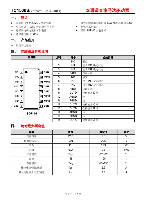
一、特点双通道内置功率MOS全桥驱动 驱动前进、后退、停止及刹车功能 超低的待机电流和工作电流低导通电阻(1.0Ω) 最大连续输出电流可达1.8A/每通道,峰值2.5A 宽电压工作范围采用SOP-16封装形式二、产品应用玩具马达驱动三、管脚图及管脚说明五、推荐工作条件(Ta=25℃)六、电气特性(Ta=25℃,VCC=3V,RL=15Ω,特殊说明除外。
)七、输入/输出逻辑表TC1508S (文件编号:S&CIC1061)双通道直流马达驱动器八、 输入/输出波形123CBAINA INB停止停止停止停止前进后退刹车LLL L HHH H ttVM-VM输出电压(OUTA-OUTB )LLHTBRBOTBRBO 九、 芯片使用注意事项1、 以上推荐电路及参数仅适用于普通遥控车玩具,其他玩具及电机驱动在使用TC1508S 时请根据实际情况来使用。
2、 持续电流驱动能力受封装形式、VDD 、VCC 、芯片差异及环境温度等因素影响,规格书给出参数仅供参考。
在实际使用中请根据产品考虑一定的余量。
3、 TC1508S 采用MOS 工艺设计制造,对静电敏感,要求在包装、运输、加工生产等全过程中需注意做好防静电措施。
DCBAINC IND停止停止停止停止前进后退刹车LLL L HHH HttVM-VM输出电压(OUTC-OUTD )TC1508S (文件编号:S&CIC1061)双通道直流马达驱动器十、 参考电路543+10uF /16V0.1uFVCCAGND INA INB PGNDOUTAOUTB 0.1uFDCMVCCINA INB INC INDINC INDOUTCOUTD 0.1uFDCMAGND PGND 十一、 封装尺寸图。
GE双电源使用说明书

GE双电源开关使用说明书V1.0广州宇象电气设备有限公司目录(一)目的方便第一次使用我司代理的GE的双电源开关产品,以GE的ZTG和其控制器MX150为例,作了简单的说明(二)GE双电源的组成1本体(ZTG)3CPS(控制电源)以ZTG为例,别的系列有所不同对于GTX相应的控制器为MX60(可选配MX90),对于ZTS相应的控制器为MX2504连接线(三)GE双电源的控制器MX150参数说明3.1控制器MX150的界面说明市电电源指示市电指示发电电源指示市电电源合闸指示市电指示发电机电源合闸指示2控制器(MX150)J5J5J6JC J7自检事件“即将出现”3.2MX150控制器的参数说明MX150的所有设置叁数:(常用参数设置见MX150参数设置)系统信息电源S1和S2的相电压电源S1和S2的频率SYSTEMINFO:系统信息Serial#:序列号Rev#:版本EventLog事件记录DATA统计记录CHANGEUSERACCESSCODE密码设定(原密码见控制器的背面)CONFIG(配置)TIMEREXERCISER(CDT单事件定时器自检程序-时间设定:1,7,14,28天,OFF.(DAILY(每天)、WEEKLY(每周)、14DAY(天)、28DAY(天)))TIMEREXERCISER(CDT单事件定时器自检程序-种类设定:XRF(有载)、NOXFR(无载)*CLOCKEXERCISER(CDP时钟自检程序:1,7,14,28天,OFF.(DAILY(每天)、WEEKLY(每周)、14DAY(天)、28DAY(天)、365DAY(天)))*TESTKEY(调试:Maintained/Momentary维护/瞬间)MOMENTARY(参数设置)TRANSFERCOMMIT(转换约定ON/OFF(开/关)。
ON:停电是接连不断的发生,如在停电延时内(还没有向S2电源转换),S1电源有电,转换开关动作;OFF:停电是一次孤立事件,如在停电延时内(还没有向S2电源转换),S1电源有电,转换开关不动作(开/关))INPHASEMONITOR(电源同步监测:ON/OFF(开/关):检查两路电源是否同步(频率是否在7个电度相位差))*PHASEIMBALANCE(VI)(3相电压不平衡监测:ON/OFF(开/关))*LOADDISCONNECTTD(UMD)(通用型电动机负载断开回路:辅助接点在以任何一个方向转换之前断开0-5分钟,转换之后,重新闭合)*NETWORK(通信功能:ON/OFF(开/关))SET(参数设置)SYSTEMCLOCK(系统时钟设定)DAYLIGHTSAVING(背光灯:ON/OFF(开/关))*CLOCKEXERCISER(CDP时钟自检程序:1,7,14,28天,OFF.(DAILY(每天)、WEEKLY(每周)、14DAY(天)、28DAY(天)、365DAY(天)))EXERS2RUNTIME(CDT单事件定时器自检程序-时间设定:1,7,14,28天,OFF.(DAILY(每天)、WEEKLY(每周)、14DAY(天)、28DAY(天)))S1UNDERVOLT(S1欠压门槛值)S2UNDERVOLT(S2欠压门槛值)S2UNDERFREQ(S2欠频门槛值)*PHASEIMBALANCE(VI)(3相电压不平衡监测-参数设定:FAIL5%,RESTORE3%)*PHASEIMBALANCE(VI)(3相电压不平衡监测-时间设定:TIMEDELAY30seconds)TIMEDELAYS2START(S2(发电机)启动延时(定义为定时器P):(0-10秒可调,标准整定3秒))TIMEDELAYS2STABLE(S2稳定延时(定义为定时器W):延时向电源2转换,时间可调范围0-5分钟)*LOADDPRDSIGNALTD(T3/W3)(电梯预信号辅助接点:在以任何一个方向转换之前断开0-60秒,转换之后,重新闭合) *LOADDISCONNECTTD(UMD)(通用型电动机负载断开回路:辅助接点在以任何一个方向转换之前断开0-5分钟,转换之后,重新闭合) ATSOPENTIMETOS2(S2延时转换(定义为定时器DW):从开关向电源2位置转换的时间延时(1-10分钟,标准设置为5秒))DW TIMEDELAYS1STABLE(电源S1稳定定时器(定义为定时器T):延时向电源1位置转换(电源2失灵情况下立即重新转换)时间可调范围0-60分钟,标准设置是30分钟ATSOPENTIMETOS1(S1延时转换(定义为定时器DT):从开关向电源1位置转换的时间延时(1-10分钟,标准设置为5秒))S2STOPDELQY(电源S2停止延时定时器(定义为定时器U):在开关重新转换至电源1以后允许发电机无载运行(1-60分钟,5分钟))CALIBRATES1(校正S1(电压,频率))CALIBRATES2(校正S2(电压,频率))TEST(调试)FASTTEST(快速调试)除发电机停机延时外所有定时器有效XFRLOAD(带负载调试)按键放后启动一次真实的转换操作。
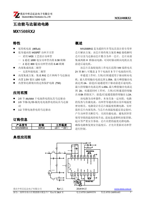
马达驱动电路MX1508RX2产品手册_V1.1
传真:0755-26895685
4
SinotechMixic Electronics Co.,LTD
MX1508RX2
电特性参数表
(TA=25℃, VM =6.5V 除非另有规定)
参数
符号 条件
电源参数
VM 待机电流
IVMST
功 率 管 导通内阻
1 通道导通内阻
IO=±200mA VM1=6.5V TA=25℃ RON1 IO=±1000mA VM1=6.5V TA=25℃
该电路为功率器件,本身具备一定内阻,电路 的发热与负载电流、功率管导通内阻以及环境温度 密切相关。电路设计有芯片级温度检测电路,实时 监控芯片内部发热,当芯片内部温度超过设定值时, 产生功率管关断信号,关闭负载电流,避免因异常 使用导致的温度持续升高,进而造成塑料封装冒烟、 起火等严重安全事故。芯片内置的温度迟滞电路, 确保电路恢复到安全温度后,才允许重新对功率管 进行控制。
℃
TJ
150
℃
Tstg
-55~+150
℃
焊接温度
TLED
260℃,10 秒
注:(1)、VM 代表 VM1 和 VM2,1 通道代表 FORWARD 和 BACKWARD 通道,2 通道代表 RIGHT 和 LEFT 通道。
(2)、不同环境温度下的最大功耗计算公式为: PD=(150℃-TA)/θJA
解码频率
内置振荡频率
FOSC
允许发射频率的偏差
电特性曲线图
最小值 典型值 最大值 单位
465
uA
0.35 0.38
Ω 0.43 0.46
2.593 2.594
V 2.584 2.595
128
扬修电动头2SA8说明书
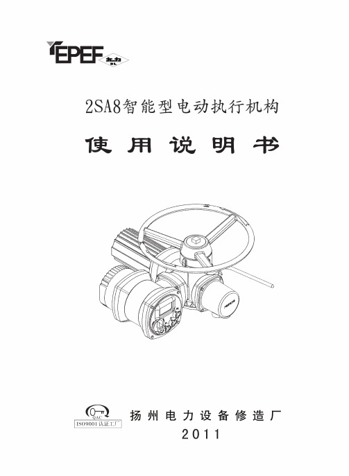
安 全该机电设备是在工业强电流的条件下使用的。
在操作中,该设备有些零部件带电,同时有些零部件能够运动或转动。
因此,未经许可拆下保护罩盖,不合理的使用,不正确的操作或不合适的维护,均会造成严重的人身伤害或设备损坏。
为了人身和设备的安全,必须保证:仅允许专业人员对设备进行作业。
在对该设备进行作业时,应按说明书的要求进行。
严禁非专业人员对该设备进行作业。
目 录1、使用须知 (1)2、工作原理与结构组成 ................................................. (1)2.12SA8系列电动执行机构工作原理 (1)2.2结构组成 (2)3、连接与安装 (2)3.1机械连接形式 (2)3.2机械安装注意事项 (3)3.3电气连接及安装 (3)3.4特殊场合的分体安装 (3)4、功能与操作 (4)4.1操作面板显示与说明 (4)4.2遥控器的使用说明 (4)4.3设置项目 (5)4.4一般功能与操作 (6)4.5高级功能与操作 (8)4.6其他功能与操作 (11)4.7紧急功能与操作 (11)5、参数浏览 (12)6、维修及保养 (13)6.1手动操作注意事项 (13)6.2维护周期 (13)6.3电池说明 (13)附录1:2SA8系列电动执行机构用户接线图 (14)附录2:2SA8系列电动执行机构主要技术参数 (16)附录3:2SA8系列电动执行机构出厂设置参数一览表 (17)附录4:2SA8系列电动执行机构可能的故障及解除办法 (18)★在安装调试2SA8系列电动执行机构前,请仔细阅读本说明书。
★本说明书如有更改,恕不另行通知!1、使用须知1) 2SA8系列电动执行机构在运输、保管、安装、调试、运行、维修时应严格按照本说明书的各项要求进行,以避免发生故障及损伤;2) 非专业工程技术人员请勿随意安装、调试、运行、维修电动执行机构;3) 吊装时,应使用缆绳套在电机及接线罩盖上起吊电动执行机构,如图1所示,不允许将缆绳系在手轮、切换手柄以及外露电缆上起吊或移动电动执行机构;4) 电动执行机构未安装使用时,应贮存在室内干燥处,安装在管道上时,管路振幅大于0.05mm(单图1 吊装示意图2、工作原理与结构组成2.1 2SA8系列电动执行机构工作原理154 3 2图2 工作原理示意图1、电动机2、蜗轮3、传感器4、输出轴5、蜗杆2SA8系列电动执行机构的电气控制组件接收外部控制信号,使电机输出动力,通过蜗杆蜗轮及离合器,最终传至输出轴,从而控制阀门阀位,达到运行的目的。
XRotor-X11-18S 单轴载荷保护系统用户手册说明书

100%34775113.27809.73909 4.5【Protection】1)Start protection:When the power is connected normally,the ESC will first start the self-test.If the self-test is successful,it will run normally after beeping.If the self-test fails,it will not start and the flashing light will warn.2)Stall Protection:When the ESC detects that the motor is locked,the ESC will completely turn off the output and will not restart the motor.At this time,it is necessary to power on again to clear the error and restart the ESC to restore power output.3)Current Protection:When it detects that the instantaneous current abnormality reaches close to300A,the ESC will restart immediately,and the output will be turned off if the detection times reach abnormality five times in a row,and it will return to normal after the power is turned on again.4)Throttle signal loss protection:When the ESC detects that the throttle remote control signal is lost for more than0.25seconds,it will immediately turn off the output to avoid greater losses caused by the continued high-speed rotation of the propeller.After the signal is restored,the ESC will immediately restore the corresponding power output.【Warning tone description】Symptom Tone Possible causes Possible solutionsMotor fails to start after power on “Beep beep beep”rapidmonotone Throttle is not reset to zeroPush the throttle to the lowest point orrecalibrate the throttle pointMotor fails to start after power on “Beep,Beep,Beep”(1second for each interval)No throttle signal input on thereceiver throttle channelCheck if transmitter and receiver isnormal.Check if wiring of throttlechannel is normalThe power-on voltage is lower than18V or higher than63V “Beep,Beep,Beep”(1second for each interval)Battery voltage is too low Replace with a full-charged battery【Daily usage】1.Adjust LED light colorUse a tool to take out the M3×8screws that fasten the lampshade,and set the switch according to the corresponding light color below(factory default green).After the setting is successful,assemble and fasten the lampshade in the original way.Dial code on/off1Dial code on/off2Dial code on/off3LED colorON ON ON WhiteON OFF ON Light blueON ON OFF PurpleON OFF OFF BlueOFF ON ON YellowOFF OFF ON GreenOFF ON OFF RedOFF OFF OFF LED on/off2.Description of light color statusSelect light color before itblinksMeaning SolutionContinuous single shortflashOver-voltage Replace the battery(battery below82V) Continuous2short flash Under-voltage Replace the battery(battery higher than18V)Continuous3short flash Over-current Power on again,and check the motor for foreign objectsContact after sales service Continuous single longflashThrottle lost-Check connection between signal line to the flight controller-Check whether the remote controller and flight controller areturned on-Check the resistance of the black and white wires,if there is ashort circuit,contact the after-sales service Continuous(Single longflash+Single short flash)Throttle not reset to zero This problem occurs during the rotation of the motor.Please check theaircraft battery and circuit.There is a short circuit on the circuit.Continuous(Single longflash+2short flash)MOS overheated(Over110℃)Cool down the power system and power on againContinuous(Single longflash+3short flashes)Capacitor overheated(Over110℃)Cool down the power system and power on againContinuous(Single longflash+4short flashes)Trigger stall protection-Restart after the throttle is reset to zero-Please check if there is any foreign matter in the motor,remove the foreign matter before starting Continuous(2longflashes)Short-circuit Please check whether the motor circuit is intactContact after sales service Continuous(2longflashes+single shortflash)Short-circuit Please check whether the motor is in good conditionContact after sales serviceContinuous(2longflashes+2short flash)Short-circuit Please check whether the motor is in good conditionContact after sales service Continuous(2longflashes+3short flash)Phase A operationalamplifier is abnormalRe-power on to return to normalContact after sales service Continuous(2longflashes+4short flash)Phase B operationalamplifier is abnormalRe-power on to return to normalContact after sales service Continuous(3longflashes)Phase C operationalamplifier is abnormalRe-power on to return to normalContact after sales service3.Abnormal LED alarm during power-onLED Tone Possible causes Possible solutions Continuous single shortflash(0.5second for eachinterval)“Beep beep beep”rapidmonotone(0.5second foreach interval)Throttle is not reset to zero Push the throttle to the lowest point orrecalibrate the throttle pointLED on“Beep,Beep,Beep”(0.5second for each interval)The output data and upgradelines has short-circuited.Check the yellow,red and green cables Continuous single shortflash(1second for eachinterval)No beep Phase is abnormal.Contact after sales service4.Replacing the propeller1)Use the appropriate tools to take out the two propeller fastening screws in and replace them with intact propellers.If you need to replace the propeller clips,continue to take out the fastening screws and replace the whole set of propeller clips and propellers.2)Installing the propeller clip blades-Firstly,install the bottom cover on the motor,followed by the propeller blades,propeller gaskets,upper cover(propeller clips)and the final screws in order;pay attention to the installation of the propeller screwsAfter clamping,the propeller should rotate freely,and make sure that the propeller clamp and the motor fastening screw are tightened and screw glue is used at the same time.5.Firmware upgradeUse the Hobbywing DataLink V2box to upgrade the program,and ESC not supported DataLink V1box.Upgrade step according to the DataLink V2box user of manual.6.ESC work data checking1),Use the Hobbywing DataLink box to check ESC work data.According to the DataLink V2box user of manual.2),ESC work data by serial communication.Flight control needs to support Haoying protocol to obtain ESC data.【After-sale maintenance】In the event that the equipment of the power system is damaged,please contact Hobbywing after-sales customer service immediately. Under the premise of not affecting the performance,make sure that you can use the Hobbywing power system kit accessories for replacement after contacting the customer ers are prohibited from configuring accessories by themselves(such as screws, paddle clips,propellers)for replacement.。
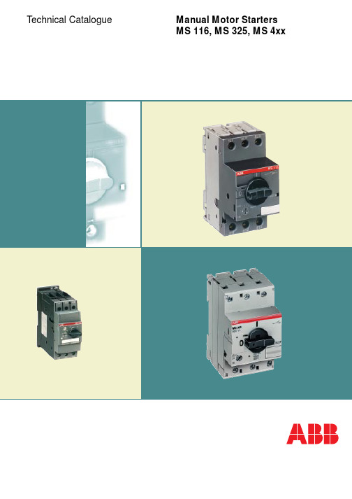
ABB手动电机启动器技术目录手册说明书
ContentsManual Motor Starter MS 1160-16 A, 16/50 kA (6)Manual Motor Starter MS 3250-25 A, 100 kA (8)Remote control unit RC 325for starter combination, 0-16 A, 50 kA (11)Busbar System smissline-S for plug inuntil 160 A, 50 kA (12)Manual Motor Starters MS 45x11-50 A, 25/50 kA (14)Manual Motor Starters MS 49x11-50 A, 25/50/100 kA (14)MO-magnetic only applicationsuntil 100 A, 25/50 kA (17)Technical data, dimensions, Short circuit switching tables (18)Examples, applications (32)Switching capabilities of ABB‘s manual motor startersManual motor starters from ABB properly switch motors ON and OFF and protect them in case of overload and short circuit.Thus, ABB‘s manual motor starter know-how increases the reliability and availability of applications thanks to the extremely quick short circuit cut-off in cases that could cause motor damage.ABB motor starter combinations constitute a reliable, cost-efficient solution for all your motor protection needs, for examples in:•General engineering and plants •Industries •Conveyor systems•Chemical industries including process engineering •Pharmaceutical industries•Automation of buildings, e. g. in air-conditionings •Environmental plants •Power stations•Fresh water and sewage plants •Machine toolsManual Motor Startersand Motor Starter Combinations0.16 A 25 A50 A100 A16 A Manual motor starters provide protection against:•Overload •Short circuit •Phase failure •UndervoltageFuseless protection saves costs and space and provides for quick reaction under short circuit condition, switching the motor off within 3 ms. It is therefore an easy to handle,cost effective protection solution.Manual Motor Starters from ABBABB offers a wide range of a manual motor starters providing highly efficient motor protection up to 100 A.The arc breaking capacity of the devices can reach up to 100 kA depending of the motor starter type used,without the necessity for any special upstream protection.Thanks to its design MS 116/325 are suitable for industrial applicatons as well as for domestic installations.The device-types MS 116/325 can be easily coordinated with the ABB MCB-system, which is used in installations for touch-proved enclosures and panels.MS 450 to MS 497 are your best choice for high power applications. These models are used to power up large motors up to 45 kW.Technical Data, OverviewMotorstarter type MS116MS 325MS 45x MS 49x I e /A 162550100I CS /kA 16/30/5050/10025/5025/50/100Tripping class 101010,2010,20Magnetic type only Disconnect Capability,ref. IEC 60947-1The types MS 325 have the lowest “energy let through”-values on the market in case of short circuits.This way cables and the wiring are also protected optimally, providing for even higher safety.Manual motor starters must be set to the rated motor demand. Higher current is needed at motor start-up.During the start-up period the manual motor starter will let the current go through and will not trip, following the pertaining international standards and curves for motor start and hold operation.MSx Tripping curvesMagnetic releaseNo thermal releaseapprox. 12 * I Factor x I T r i p p i n g t i m e m s e cMO-types1 1.52346810152030406080Multiple of the rated currentMS 116 with mini contactor B6MS 116Manual Motor Starter MS 116AccessoriesOrdering detailsHKF 1-11MS 116 with A-contactorDirect adapterS S T 11601S T O 23014M S 116m 3bM S 116m 2bS T O 18014Open design, enclosure IP 20, resistant to changeable climates. Quick fastening on mounting rails DIN EN 50 022, 35 mm without auxiliary switch.ቢ Not suitable for panel mountingPadlock + 2 keys + lock adapterS 0109B 91 + S K 0150B 91Manual Motor Starter MS 116AccessoriesOrdering detailsSwitch cubicle mounting kitPower infeed block S1-M1Power infeed block S1-M2Phase buses PS1-2-1Phase buses PS1-4-1Insulatingenclosure IP 55Insulatingenclosure IP 65Plastic enclosure IP 40S T O 21014S T O 22014S T O 19014S T O 20014S T O 28014G E H _u s e sS T O 2701462-00-bAccessoriesባ Is srewed directly onto the manual motor starterMS 325 withauxiliary contacts HKF-11 front mountingSST2899Manual Motor Starter MS 325 Ordering detailsMS 325SST1497SelectionOpen design, enclosure IP 20, resistant to changeable climates. Quick fastening on mounting rails DIN EN 50 022, 35.S S T 009 95 RS S T 290 92 RSKASHKS S T 016 97S S T 309 92 RS S T 032 95 RUA for power in feed at bottomUA for power in feed at top, AAHKFManual Motor Starters MS 325Accessories Ordering details63-0Retrofittable accessoriesThese parts can be procured in addition to the MS 325; they must be installed by the user.ቢ Not simultaneously with UA/UA and AA, not suitable for distributor installationባ Max. 1 piece in conjunction with SK. SK must be mounted on first position ቤ Pre-mating normally open contactsብ Can be used together with UAF (power infeed at top) for safety circuit with Emergency Stop button (further information available on request)ቦ Other voltages, in particular DC, on requestቧ In particular if used with socke busbar system smissline-S (see Page 13)ቨ Recommendation: Connection of external voltage via terminal support ASS S T 30992RPadlock + 2 keys + lock adapterS 0109B 91 + S K 0150B 91S S T 022 93 RS S T 021 93 RS ST 023 93 RS S T 024 93 RDirect adapterSwitch cubiclemounting kitManual Motor Starters MS 325Accessories Ordering detailsPower infeed block S3-M1Power infeed block S3-M2Phase buses PS3-2-1Phase buses PS3-4-1Insulatingenclosure IP 55Insulatingenclosure IP 65S T O 28014S T O 18014S T O 3201462-00AccessoriesManual Motor Starter MS 325 AccessoriesOrdering details, Technical dataRC 325 mounted at MS 325RC 32558-SST2-switchingoperationsI e MS 325SST3--Wiring diagramA2T1, T2, T3542214132153MS 325RC 325A1L1, L2, L3>Mechanical and electronicaltime life AC-3, 400 VRemote Control Unit RC 325The Remote Control Unit RC 325is suitablefor manual motor starters type MS 325 up to16 A.With RC 325 and MS 325 customers willreceive a complete, fully coordinated startercombination, type I and type II in only oneproduct.This combination doesn’t need a backupfuse for a short circuit protection up to 60 kAat 16 A. The combination is fully coordinatedand after a short circuit event no contactswill be welded.Users will achieve a high availability sincethe combination‘s functionality is fullyrestored after a short circuit.Moreover, the combination is compact andsaves space and costs in operation.)RC 325 and MS 325 together work as amanual motor starter/contactor combination.The control circuit must be connected toRC 325 which controls MS 325. To startoperation, the MS 325 has to be switchedto its “ON”-position. The RC 325 thencontrols the main contacts of the MS 325for switching a motor or another load. Inthe event of a short circuit the manualmotor starter will trip. For restarting MS 325must be switched to its “ON”-position again.(RC 325 acts on 1 NO and 1 NC contact.The NO contact may operate as lockingcontact and the NC-contact may be usedOrdering detailsባ If RC 325 is used - auxiliary devices as HKF, HK, SK, shunt-, undervoltage- release are not suitable at the same time.57-12Busbar system smissline-S for MS 325Manual Motor Starter for plug inSmissline-S is a powerful busbar system for the quick and easy in-stallation of manual motor starters type MS 325 up to 160 A.A user of this system not only will save time and wiring costs in elec-trical installations but will be rewarded with increased safety. This powerful system offers large advantages in a current range up to 160 A with a short circuit capacity of 50 kA.ABB offers smissline modules in various lengths that are ready-made for directly mounting the MS 325 according to a simple plug-in philosophy – an ideal solution for fast installations with high wiring safety.socketbusbar S S T 03797supply in center: max. 160 AS S T 40426Smisslin-S is a proven system which has been succesfully installed in numerous hospitals, as well as in office and commercial buildings,power plants, industrial installations or in production lines. Smissli-ne-S can be installed either horizontally or vertically.In no time at all components can be changed or replaced safely in operation – a huge advantage for a quick and efficient service.Thus the installation achieves a very high availability and safety.13Busbar system smissline-S for MS 325Manual Motor Starter for plug inS K 0120 B 93ZLS 100S K 0121 B93ZLS 101S K 0087 B 94ZLS 930S K 0119 B 93ZMS 915ZLS 756S S T 40277S K 0197 B 93ZLS 224/225S S T 40158ZLS 802Busbar module incl. sockets,busbars and end pieces14MS 495 with A95connected via BEA 110/495S S T 09498MS 495 with auxiliary switch HKS4-02 and open-circuit shunt release AA4 in addition to terminal shroud KA495CS T 14-02MS 49xS S T 01898MS 45xS S T 02198Manual Motor Starters MS 4xxOrdering detailsSelectionopen design. enclosure IP 20, resistant to changeable climates. Quick fastening on mounting rails DIN EN 50 022, 35 mm without auxiliary switch15S S T 09198Pilot switch SK4-11S S T 01599Manual Motor Starters MS 4xxAccessories Ordering detailsAuxiliary switch HK4-11Auxiliary switch HKS4-02S S T 08598Open-circuit shunt release AA4S S T 07798Undervoltage release UA4-HKS S T 8698Retrofittable accessoriesThese parts may be procured in addition to the MS 4xx.They must be mounted by the user.ቢIs plugged onto the box terminals in each case ብMounting sequence: Motor protection switch, pilot switch, auxiliary switch ባIs plugged onto the housing after removing ቦ Max. ON time: 5 seconds, see also Page 20the box terminals, if using cable lugs or buses ቧSee also MS325 Page 10ቤSupplied only as a set as 10 scale covers ቨIs screwed directly onto the manual motor starterStrategies for Motor protection with magnetic only types MOFor special applications ABB’s manual motor starterof the MS series are also available as versionsMO 325 / MO 450 / MO 495 with magnetic tripping only, protecting exclusively against short circuits.However, combined with intelligent ABB-components, the starter series MO open up further interesting alternatives for the use of motor starters, especially when short circuit protection and thermal protection have to be realized independent from one another.Therefore three different strategies of motor protection with manual motor starters MO from ABB are feasible: 1.With thermal overload relays:cost efficient protection against overload andphase failure2.With electronic overload relays:For high accuracy and efficient stock planing,less types for the complete range, highflexibility.3.Thermistor motor protectionwith electronic relays Custorapid®:High accuracy with temperature monitoringdirectly in the coil, highly efficient protectionwith several electronic posibilities.Examples for motor protectionup to 25 A up to 50 A up to 100 A1617Magnetic only types MO 4xx - circuit breakersOrdering detailsS S T 02198S S T 01898SelectionThe tripping curves show the tripping time dependend on the factor of the selected motor current. The values have a tolerances of approx. +/- 20%.Standard manual motor starters have thermal protection against overload, a magnetic protection against short circuit and a protection against phase failure.Types MOxx protect only against short circuit. The thermal release and phase failure are not in functon.Applications are:Short circuit protection against resistance loadsShort circuit protection using TOL for thermal protectonOnly short circuit protection for loads where a tripping curve 12 ...14 x In is requiredቤAlso applies to auxiliary switches HKF1 and undervoltage release UA1ብFor auxiliary switch HKF.. Pozidrive 2ቦApplies to auxiliary switches HK1 and SK1Manual Motor Starters Type Series MSTechnical dataSST1497SST2198SST1898SST116118Manual Motor Starters Type Series MSTechnical data19Manual Motor Starters Type Series MSTechnical dataቢCurrent ranges 0.16 to 0.63 AባCurrent ranges 1 to 2.5 AቤCurrent ranges 4 to 6.3 AብCurrent ranges 9 to 25 Aቦ24-60 V: 14.4-90 VA20Manual Motor Starters Type Series MSTechnical dataShort-circuit protection MS 116, setting ranges, short-circuit strength and max. back-up fusesMaximum rated current of the short-circuit fuses if I cc > I cs ቢቢI cs =Rated service short-circuit breaking capacity, I cu = Rated ultimate short-circuit capacity, I cc = Prospective short-circuit current at installation location.I cs =I cu in the case of MS 325 and MS 116!21Manual Motor Starters Type Series MSTechnical dataShort-circuit protection MS 450 / MS 451, setting ranges, short-circuit strength and max. back-up fusesቢ I cs = Rated service short-circuit breaking capacity, I cu = Rated ultimate short-circuit breaking capacity I cc = pProspective short-circuit current at installation location.Manual Motor Starters Type Series MSTechnical dataCoordination acc. IEC / EN 60947-4-1The following table lists the combinations of motor protection switches and contactors according to assignment type 2 in compliance with IEC / EN 60947-4-1Further coordination tables on requestForward current integrals (lt2 curves) on requestPeak forward current curves on requestReliable line protectionManual Motor Starters Type Series MSTechnical dataTimes to tripSelection table for suitability of the motor protection switches for motors of enclosure eTime to trip of the motor protection switches as a function of a multiple of the setting current (tolerance 20 % of the time to trip).PTB approvals, see below.Ident-numbersof manual motor starters for motors with EEx e-Protection:Type Ident-No.MS 325 3.53 - 1357/94National Institute for Standards and TechnologyMS 450, MS 495, MS 497Ex - 99.Y.74976KEMAApprovals and certificatesCSA GL LRS BV DNVCanada USA Germany Great Britain France Norway M M m mM Normal version approved: Rating plates bear the test mark if mandatory.m Submitted for approval, delivery time on request.13211422I >21I >43I >6507D108U <D2U <D1D212141157657785C1C2Manual motor starter MS 116 with accessories in accordance with the adjacent captionManual Motor Starters Type Series MSWiring diagramsManual motor starter MS 325 with accessories in accordance with the adjacent captionቪቫቢባቤManual motor starterfor switching direct current and single-phase alternating currentManual motor starter MS 4xxin accordance with the adjacent captionቢባManual Motor Starter MS 116AccessoriesDimension diagramsDimension in mm 17785,645HKF1-11BEA16/11615985,645BEA7/116B6 / B7HKF1-11Manual motor starter MS 116 mounted with contactor A9...A16Manual motor starter MS 116 mounted with mini contactor B6/7Manual Motor Starters MS 325AccessoriesDimension diagramsDrilling planDriver and spindlesT 216 98Mounting depth mm 90137157182Axial length mm3285105130S S T 105 92 MSwitch cubicle mounting kitS S T 214 98Outer twist knobsDrilling planS S T 201 99driveraxismounting depthHandledriverAxis 85...180 mmdriver spindle 32 mmDimension in mmManual Motor Starters MS 325AccessoriesDimension diagrams95Mounting platestarter combination for plug into busbar system smissline-SDimensions in mmwidthdepthh e i g h tt o t a l h e i g h tBusbar system smissline-SDimensions in mmS K 0251 Z 93Motor protection switch MS 325 3 PLE259 Z 93Auxiliary switch block HK with empty housing ZLS 9301 PLES S T 9003Auxiliary switch block HKS4Pilot swich SK4Open-circuit shunt release/undervoltage release AA4, UA4, UA4-HK Auxiliary switch HK4ÁTop-hat rail 35 mm to DIN EN 50022Top-hat rail 35 mm, 15 mm high to DIN EN 50022or Top-hat rail 75 mm to DIN EN 50023ÂSwitch knob lockable in zero position with bracket diameter 5 mmMotor manual starter MS 45xMotor manual starter MS 49xS S T 9004S S T 8193MS 45x with disconnector module TB 450Manual Motor Starters MS 45x / MS 49xDimension diagramsNotesManual Motor Starter MS 325Combinations with AccessoriesMS 325with undervoltage release UAFMS 325 with auxiliary switch HKcross-wired with phase buses and power infeed blockMS 116 cross wired via phase busses and power infeed blocks S S T 02597S T 01501QES 6/3 NMS 325 with RC 325 in PCD 6 NS S T 02297S T 01601Insulatingenclosure IP 65Manual Motor Starter MS 325Combinations with AccessoriesMS 325 + HK + SK withcompact reversing contactor VB 6MS 325 + HKF with contactor A 16S S T 09698MS 325 with contactor A 26on busbar adapter SA 11S T 02401S T 03201Insulating enclosure IP 65 with locksMS 495 with A95connected via BEA 110/495The new FBP (FieldBusPlug) product family is a communication device range of switching and automation components whichcan be combined easily with standard fieldbus systems.Manual Motor Starter Application: Switching on/off, Disconnection and locking for service, MotorprotectionRC 325 and MS 325 - this smart motor starter combination is quite an innovative solution for protecting and switching remotely,all in one single device, automatically coordinated up to 100 kA.It can be plugged into the manual motor starter MS 325 laterally.As an innovative and extremely compact motor starter combination it provides the designengineer with a powerful yet easy to use modulardevice for switching, protecting and remote controlling of a motor.Customer Benefits•Remote control for MS 325•Compact starter according to IEC 60947-4-1•No need for additional coordination,thanks to mechanical interlockTechnical data for the compact motor starter Operating current:up to 16 AShort circuit range:up to 100 kASwitching capacity:up to 1.000.000 operations Several control circuits RC 325are available in a wide voltage rangeCompact motor starterManual Motor Starter MS 325 and switching Unit RC 325Various Motor Starter combinationsThe manual motor starters from ABB are designed to be easily coordinated with various other components from ABB tors Series “B”.Such a modular philosophy brings endusers an emproved service and faster reactionsin operating systems.Various Motor Starter combinationsA unit MS 116/325 can be clipped,forming an automatically connected motor starter combination.Fast front connection, compactdimensions and a robust design are only the most obvious advantages of ABB’s motor starters.Seperate gear conceptIndividual devices for single wiring.Manual motor starter and contactor can be wired according to customer demands.•cost efficient•reliable•space-savingCustomer benefits:•fully coordinated modular assembly •easy planning •no wiring necessary •compact - space saving •easy to change•better and quicker service •FBP connection to field bussesDOL StartersModular conceptMotor starter Combinationswithout or with field bus connection.ABB STOTZ-KONTAKT GmbH P .O. Box 10168069006 Heidelberg GermanyPhone:+49 (0) 62 21 / 7 01-0Fax:+49 (0) 62 21 / 7 01-729Internet:www.abb.de/stotz-kontaktDevice type Approvals Ships’ classification societiesTest markAbbreviation CSA USAPTB GL LRSBV DNV Validity CanadaGermany Germany Great Britain France NorwayMS 116MS 325MS 45xMS 49xP u b l i c a t i o n N o .: 2C D C 130 002 C 0203 P r i n t e d i n t h e F e d e r a l R e p u b l i c o f G e r m a n y (10/03 · 5 · G V D )。
大农器具有限公司 Universal Robots 2200系列传输器服务手册说明书
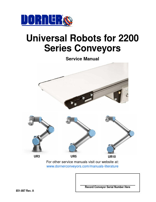
For other service manuals visit our website at:/manuals-literature851-897 Rev. ARecord Conveyor Serial Number HereUniversal Robots for 2200Series ConveyorsService ManualUR3UR5UR10Dorner Mfg. Corp.2851-897 Rev. AUniversal Robots for 2200 Series ConveyorsTable of ContentsTable of Contents......................................................................................................................................................................... 2Introduction.................................................................................................................................................................................. 3Warnings – General Safety........................................................................................................................................................... 4Dorner URCap Setup and Installation.......................................................................................................................................... 5Setup and Installation................................................................................................................................................................ 5Programming with the Dorner URCap......................................................................................................................................... 6Installation Node....................................................................................................................................................................... 6Inputs..................................................................................................................................................................................... 6Outputs.................................................................................................................................................................................. 6Programming Conveyor Nodes ................................................................................................................................................ 7Toolbar...................................................................................................................................................................................... 8Wiring Examples........................................................................................................................................................................ 10Dorner Full Feature Variable Frequency Drive...................................................................................................................... 10Drive Programming............................................................................................................................................................. 10Wiring Diagram .................................................................................................................................................................. 11Dorner Full Feature Variable Frequency Drive European Version........................................................................................ 12Drive Programming............................................................................................................................................................. 12Wiring Diagram .................................................................................................................................................................. 13Return Policy (14)851-897 Rev. A3Dorner Mfg. Corp.Universal Robots for 2200 Series ConveyorsIntroductionDorner Mfg. Corp. has worked directly with Universal Robots to develop software to control 2200 Series conveyors using the Universal Robot controller. The UR controller requires the installation of a software file referred to as URCap. URCap makes the integration of Dorner conveyors easier for customers to setup configure and control. The Dorner conveyor URCap can be downloaded from our website, https:///dorner-ursolutions .Once installed in the UR controller, the conveyors can be added to the control program being created and allow the user to program the inputs and outputs needed for starting, stopping, speed reference, and status information (see Figure 1).The Dorner URCap has been designed for both CB series and e-series controllers.Programming for the variable speed drive should be done using the Frequency Inverter Operating Instructions manual.Robot programming manual will be supplied with robot or can be found at the Universal Robots site https:///.Figure1Dorner Mfg. Corp.4851-897 Rev. AUniversal Robots for 2200 Series ConveyorsWarnings – General SafetyWARNINGThe safety alert symbol, black triangle with white exclamation, is used to alert you to potential personal injury hazards.SEVERE HAZARD!KEEP OFF CONVEYORS. Climbing, sitting,walking or riding on conveyor will result in death or serious injury.WARNINGSEVERE HAZARD!LOCK OUT POWER before removing guards or performing maintenance. Exposed moving parts can cause serious injury.WARNINGBURN HAZARD!DO NOT TOUCH the motor while operating, or shortly after being turned off. Motors may be HOT and can cause serious burn injuries.WARNINGPUNCTURE HAZARD!Handle drive shaft keyway with care. It may be sharp and could puncture the skin, causing serious injury.EXPLOSION HAZARD!•DO NOT OPERATE CONVEYORS IN AN EXPLOSIVE ENVIRONMENT. The electric gearmotor generates heat and could ignite combustible vapors.•Failure to comply will result in death or serious injury.WARNINGCRUSH HAZARD!•DO NOT place hands or fingers inside the conveyor while it is running.•DO NOT wear loose garments while operating the conveyor. Loose garments can become caught up in the conveyor.•Failure to comply could result in serious injury.WARNINGCRUSH HAZARD!•SUPPORT CONVEYOR SECTIONS PRIOR TO LOOSENING STAND HEIGHT OR ANGLE ADJUSTMENT SCREWS.•Loosening stand height or angle adjustment screws may cause conveyor sections to drop down, causing serious injury.WARNINGSEVERE HAZARD!•Dorner cannot control the physical installation and application of conveyors. Taking protective measures is the responsibility of the user.•When conveyors are used in conjunction with other equipment or as part of a multiple conveyor system, CHECK FOR POTENTIAL PINCH POINTS and other mechanical hazards before system start-up.•Failure to comply could result in serious injury.851-897 Rev. A5Dorner Mfg. Corp.Universal Robots for 2200 Series ConveyorsDorner URCap Setup and InstallationSetup and Installation1.Download Dorner URCap from https:///dorner-ursolutions .2.Load file DornerConveyor-1.x.x.urcap onto a memory stick.3.Plug memory stick into USB port on Universal Controller teach pendant (see Figure 2).Figure 24.Follow URCap installation process in the Setup Robot section of programming:a.Click the + button to install the Dorner URCap. Click the - button to uninstall.b.Select the DornerConveyor-1.x.x.urcap file and click open c.The URCap will be opened and returned to the setup screend.When installing or uninstalling a URCap, a restart is required. Press Restart.5.The URCap is now installed.Status of the URCap in the setup screen:SymbolMeaning1URCap ok: Installed and running2URCap fault: The URCap is installed but unable to start. Contact Dorner Mfg. Corp.3URCap restart needed: The URCap has been installed and needs to be restartedDorner Mfg. Corp.6851-897 Rev. AUniversal Robots for 2200 Series ConveyorsProgramming with the Dorner URCapThe installation is capable of controlling 1 or 2 Dorner conveyors. Enable each conveyor to be used, configure the inputs and outputs that will be used to control the variable frequency drive, and the scaling for the speed reference.Installation NodeEnable the conveyors for use:•Enable conveyor 1 and/or conveyor 2 to be used with the Universal Robot (see Figure 3).Figure 3InputsConfigure the inputs that the controller will receive from the variable frequency drive. These inputs are application dependant:•Faulted - input to the controller from the VFD signaling that it has faulted•At Speed - input is configurable to controller from the VFD signaling a status programmed in the VFD using the relay output•Load - input is an analog signal from the drive for the amount of load. This can be torque or current where 0-100% will equal 0-10V or 0(4)-20mAOutputsConfigure the outputs that the controller will send to the VFD:•Forward (Run) - output to the VFD signaling it to start/run •Reverse - output to the VFD signaling it to run reverse•Clear fault - output to the VFD signaling it to clear a fault on the VFD when present•Conveyor Speed - analog output that can be configured for 0-10V DC or 0(4)-20mA as the speed reference for controlling the speed of the conveyor motor•Conveyor Rate - is used for scaling the speed reference and should be the conveyors maximum speed in millimetres per second•Run Required Check Box - this check box is used when both the Start/Run and the Reverse signals are required at the sametime in order for the VFD to control the motor in the reverse direction851-897 Rev. A7Dorner Mfg. Corp.Universal Robots for 2200 Series ConveyorsProgramming with the Dorner URCapProgramming Conveyor NodesWhen adding the conveyors to the program structure, the following window allows the user to program which conveyor needs to be inserted into the logic at that point. Select Conveyor #1 or Conveyor #2 and the desired control for the VFD.NOTE: This is an empty program node - not set up yet (see Figure 4).Figure 4NOTE: This is a completed program and program node (see Figure 5). Highlighted program node is displayed in right side of image. Text in program node identifies the action to be performed.Figure5Dorner Mfg. Corp.8851-897 Rev. AUniversal Robots for 2200 Series ConveyorsProgramming with the Dorner URCapToolbarIn the e-series controller, a toolbar for Dorner conveyors is available at the top of the screen (see Figure 6).Figure 6When pressed, the toolbar brings up the Dorner conveyor status page that allows the user to see the fault status, speed, load,and if needed, jog the motor in a forward or reverse direction (see Figure 7).Figure 7NOTE:1.Fault & fault reset are available, as they are configured in the installation tab.2.Option “At Speed” is set up by choosing what output is configured from the VFD to the controller.3.Load displays percent of load configured by terminal 30 and P150 in the VFD.4.Jog section is only enabled when the program is not running. Conveyors will move at the speed selected as long as the button is pressed.851-897 Rev. A9Dorner Mfg. Corp.Universal Robots for 2200 Series ConveyorsProgramming with the Dorner URCapFor Universal Robots with CB series controllers, the loading, programming and control are the same as the e-series. The screens may look different due to the screen size difference. The CB series does not have the Dorner URCap toolbar functionality (see Figure 8).Figure8NOTE: This is an empty program node - not set up yet (see Figure9).Figure 9NOTE: This is a completed program and program node. Highlighted program node is displayed in right side of image. Text in program node identifies the action to be performed (see Figure 10).Figure 10Dorner Mfg. Corp.10851-897 Rev. AUniversal Robots for 2200 Series ConveyorsWiring ExamplesDorner Full Feature Variable Frequency DriveFigure 11Drive ProgrammingParameters:NOTE: This is an example. Inputs, outputs, and programming can be changed based on application.Figure12P100 1 Terminal Strip Control P101 1 - 10V DC P112 1 Fwd/RevP12110 Reverse Rotation P12220 Clear Fault P140 4 Inverse Fault P142 6 At Speed P1501 - 10V DC LoadUniversal Robots for 2200 Series Conveyors Wiring ExamplesWiring DiagramFigure13851-897 Rev. A11Dorner Mfg. Corp.Dorner Mfg. Corp.12851-897 Rev. AUniversal Robots for 2200 Series ConveyorsWiring ExamplesDorner Full Feature Variable Frequency Drive European VersionFigure 14Figure 15Drive ProgrammingParameters:NOTE: This is an example. Inputs, outputs, and programming can be changed based on application.P-120 Control Signal Terminals P-158 DI1 Start, DI2 Fwd/Rev P-160 - 10V DCP-18 3 Error Message (Not Ready)P-259 Output CurrentUniversal Robots for 2200 Series Conveyors Wiring ExamplesWiring DiagramFigure16851-897 Rev. A13Dorner Mfg. Corp.851-897 Rev. AReturn PolicyReturns must have prior written factory authorization or they will not be accepted. Items that are returned to Dorner without authorization will not be credited nor returned to the original sender. When calling for authorization, please have the following information ready for the Dorner factory representative or your local distributor: and address of customer.2.Dorner part number(s) of item(s) being returned.3.Reason for return.4.Customer's original order number used when ordering the item(s).5.Dorner or distributor invoice number. Include part serial number if available.A representative will discuss action to be taken on the returned items and provide a Returned Materials Authorization (RMA) number for reference. RMA will automatically close 30 days after being issued. To get credit, items must be new and undamaged. There will be a return charge on all items returned for credit, where Dorner was not at fault. It is the customer’s responsibility to prevent damage during return shipping. Damaged or modified items will not be accepted. The customer is responsible for return freight.Returns will not be accepted after 60 days from original invoice date. The return charge covers inspection, cleaning, disassembly, disposal and reissuing of components to inventory. If a replacement is needed prior to evaluation of returned item, a purchase order must be issued. Credit (if any) is issued only after return and evaluation is complete.Dorner has representatives throughout the world. Contact Dorner for the name of your local representative. Our Customer Service T eam will gladly help with your questions on Dorner products.For a copy of Dorner's Warranty, contact Dorner, an authorized sales channel or visit our website: .For replacement parts, contact an authorized Dorner Service Center or the factory.Product TypeStandard ProductsEngineered to order partsProduct Line Conveyors Gearmotors & Mounting Packages Support Stands Accessories Spare Parts (non-belt)Spare Belts - Standard Flat Fabric Spare Belts - Cleated & Spec. FabricSpare Belts - Plastic Chain All equipmentand parts 1100 Series 30% return fee for all products except:50% return fee for conveyors with modular belt,cleated belt or speciality beltsAll Electrical items are assigned original manufacturers return policy.non-returnablecase-by-case2200 Series 3200 Series Pallet Systems FlexMove/SmartFlex GAL Series All Electrical 7100 Series 50% return fee for all products7200/7300 Series AquaGard 7350 Series Version 2GES Series AquaGard7350/7360 Series non-returnableAquaPruf Series。
马达驱动IC芯片MX118产品手册

MX118
典型波形图
正转 输入 信号 INA INB
L H L
反转
L H L
刹车
H H
待机
VDD 输出电压 0 (Vout1-Vout2) -VDD
绝对最大额定值(TA=25℃)
参数 最大逻辑和控制电源电压 最大输出电源电压 最大外加输出电压 最大外加输入电压 每通道峰值输出电流 最大功耗 结到环境热阻 θJA 符号 VCC(MAX) VDD(MAX) VOUT(MAX) VIN(MAX) IOUT(PEAK) DIP8 SOP8 DIP8 SOP8 Topr TJ Tstg TLED 值 6.8 6.8 VDD VCC 2.5 1.16 0.67 107 184 -20~+85 150 -55~150 260℃,10 秒 2000V 单位 V V V V A W W ℃/W ℃/W ℃ ℃ ℃
重庆中科芯亿达电子有限公司 深办: 深圳市南山区艺园路 125 号马家龙田厦 IC 产业园 A402
Rev1.53 2011-11-30 2 电话:0755-26099570 传真:0755-26895685
Sinotech Mixic Electronics Co.,LTD
MX118
特别注意事项: 1、MX118 输入级无下拉电阻,测试时两个输入信号不允许悬空。必须连接至电源引脚或者地引脚; 2、MX118 功率电源端附近的去耦电容必须就近连接,必须添加,否则容易造成电路击穿; 3、MX118 功率电源对地去耦电容容质可根据电机适当调整,图中给出的电容值为参考值。 4、图 6 中 OA 与 OB 端连接到地的 104 电容为旁路电容,在三节至四节电池的应用条件下建议添加,该 电容可有效改善因电机快速正、反转切换而引起的电压尖峰击穿输出端口问题。
Maxi-Power 150 T4F 电源生成器零件手册说明书

Parts ManualMAXI-POWER™ 150 T4FCopyright © 2019 AllmandHoldrege, NE, USA 68949 All rights reserved.Part No.: 116705Revision: AenTABLE OF CONTENTS1.0 TRAILER PARTS GROUPTrailer Axle, Jack, and Coupler ....................................................................(1.1) Front Enclosure Panels ..................................................................................(1.2) Left Enclosure Panels and Doors ..................................................................(1.3) Right Enclosure Panels and Doors ...............................................................(1.4) Rear Enclosure Panels ...................................................................................(1.5) Top Enclosure Panels ....................................................................................(1.6) Door Panel Urethane Foam Linings ..............................................................(1.7) Cover Panel Urethane Foam Linings ...........................................................(1.8)2.0 ENGINE AND GENERATOR GROUPJohn Deere 6068HFG05 Engine and Filter Group .......................................(2.1) Engine Finger and Fan Guards .....................................................................(2.2) Engine Air Intake Group ..............................................................................(2.3) Engine Exhaust Group ...................................................................................(2.4) Engine Cooling Group ....................................................................................(2.5) Engine DEF System Group ...........................................................................(2.6) Fuel Tank and Fuel Lines ..............................................................................(2.7) Engine Mounting and Generator Assembly Group .....................................(2.8)3.0 ELECTRICAL GROUPControl Box Group .........................................................................................(3.1) Electrical Outlet Box Group ...........................................................................(3.2) Battery Cables Group ....................................................................................(3.3) Tail Lights and Tail Light Harness ..................................................................(3.4) Cam Lock Group .............................................................................................(3.5) Battery Charger, Battery Heater, and Block Heater .......................................(3.6) Maxi-Power™ 150 T4F Parts CatalogTABLE OF CONTENTS4.0 DECALSFront, Left, and Rear Side Enclosure Decals ...............................................(4.1) Right and Top Side Enclosure Decals .........................................................(4.2) Control and Outlet Box Decals ....................................................................(4.3) Trailer Interior Decals .....................................................................................(4.4)©2019 Allmand®SN 27-000100 and UP 1.1 - Trailer Axle, Jack, and CouplerTo Be Determined000000_AMaxi-Power™ 150 T4F Parts Catalog1.1SN 27-000100 and UP 1.1 - Trailer Axle, Jack, and Coupler©2019 Allmand®1.1SN 27-000100 and UP 1.2 - Front Enclosure PanelsSN 27-000100 and UP 1.2 - Front Enclosure Panels©2019 Allmand®1.2SN 27-000100 and UP 1.3 - Left Enclosure Panels and DoorsSN 27-000100 and UP 1.3 - Left Enclosure Panels and Doors©2019 Allmand®1.3SN 27-000100 and UP 1.4 - Right Enclosure Panels and DoorsSN 27-000100 and UP 1.4 - Right Enclosure Panels and Doors©2019 Allmand®SN 27-000100 and UP 1.5 - Rear Enclosure PanelsSN 27-000100 and UP 1.5 - Rear Enclosure Panels©2019 Allmand®SN 27-000100 and UP 1.6 - Top Enclosure PanelsMaxi-Power™ 150 T4F Parts CatalogSN 27-000100 and UP 1.6 - Top Enclosure Panels©2019 Allmand®SN 27-000100 and UP 1.7 - Door Panel Urethane Foam LiningsMaxi-Power™ 150 T4F Parts CatalogSN 27-000100 and UP 1.7 - Section One©2019 Allmand®SN 27-000100 and UPSN 27-000100 and UP 1.8 - Cover Panel Urethane Foam Linings©2019 Allmand®SN 27-000100 and UP 2.1 - John Deere 6068HFG05 Engine and Filter GroupMaxi-Power™ 150 T4F Parts CatalogSN 27-000100 and UP 2.1 - John Deere 6068HFG05 Engine and Filter Group©2019 Allmand®SN 27-000100 and UP 2.2 - Engine Finger and Fan GuardsMaxi-Power™ 150 T4F Parts CatalogSN 27-000100 and UP 2.2 - Engine Finger and Fan Guards©2019 Allmand®SN 27-000100 and UP 2.3 - Engine Intake GroupMaxi-Power™ 150 T4F Parts CatalogSN 27-000100 and UP 2.3 - Engine Intake Group©2019 Allmand®SN 27-000100 and UP 2.4 - Engine Exhaust GroupSN 27-000100 and UP 2.4 - Engine Exhaust Group©2019 Allmand®SN 27-000100 and UP 2.5 - Engine Cooling GroupMaxi-Power™ 150 T4F Parts CatalogSN 27-000100 and UP 2.5 - Engine Cooling Group©2019 Allmand®SN 27-000100 and UPMaxi-Power™ 150 T4F Parts CatalogSN 27-000100 and UP 2.6 - Engine DEF System Group©2019 Allmand®SN 27-000100 and UPMaxi-Power™ 150 T4F Parts CatalogSN 27-000100 and UP 2.7 - Fuel Tank and Fuel Lines©2019 Allmand®SN 27-000100 and UPMaxi-Power™ 150 T4F Parts CatalogSN 27-000100 and UP 2.8 - Engine Mounting and Generator Assembly Group©2019 Allmand®SN 27-000100 and UPMaxi-Power™ 150 T4F Parts Catalog3.1 - Control Box Group11820231719191425202426202810271110333342302934351634329215312213421578126CONTROL PANEL DETAILCHANGE DEVICESIDE DETAILCONTROL BOX INTERIOR DETAILSN 27-000100 and UP 3.1 - Control Box Group©2019 Allmand®SN 27-000100 and UPMaxi-Power™ 150 T4F Parts Catalog3.2 - Electrical Outlet Box Group192325303127262224292813824131439423943151720392116397898793TERMINAL PLATE DETAIL21065432323340363534373741111218OUTLET PANEL DETAILSN 27-000100 and UP 3.2 - Electrical Outlet Box Group©2019 Allmand®SN 27-000100 and UP 3.3 - Battery Cables GroupSN 27-000100 and UP 3.3 - Battery Cables GroupSN 27-000100 and UP 3.4 - Tail Lights and Tail Light HarnessTo Be Determined000000_ASN 27-000100 and UP 3.4 - Tail Lights and Tail Light HarnessSN 27-000100 and UP3.5 - Cam Locks Option115304_A678510348976211111312SN 27-000100 and UP 3.5 - Cam Locks OptionSN 27-000100 and UP 3.6 - Battery Charger, Battery Heater, and Block Heater (1 of 2)117427_A532126241BATTERY CHARGER INSTALL RECESSED PLUGS INSTALLSN 27-000100 and UP 3.6 - Battery Charger, Battery Heater, and Block Heater (1 of 2)SN 27-000100 and UP 3.6 - Battery Charger, Battery Heater, and Block Heater (2 of 2)SN 27-000100 and UP 4.1 - Front, Left, and Rear Side Enclosure Decals。
马达使用手册要点
Anadrill PowerPak Steerable Motor Handbook1.0 介绍1.1 钻井马达的发展1.2 PowerPak马达的设计和测试1.3 应用2.0 PowerPak马达描述2.1 顶部接头2.2 动力部分2.3 传动部分2.4 轴承部分和驱动轴2.5 弯壳部分和连接扣型3.0 作业3.1 常用参数3.2 狗腿严重度限制3.3 工作准备3.4 马达的现场操作3.5 空气钻井3.6 短半径钻井3.7 打捞马达4.0 地质导向系统5.0 操作参数6.0 司钻手册1。
2 PowerPak 的设计和测试PowerPak马达是根据DD的要求而设计的,特别需要强调的是,粗糙,朴素,已证明的技术已经转变为了在工作现场占优势的,可信赖的作业。
Anadrill 遵循使井底系统接近最小的噪音对MWD测量数据的干扰,以及确保PowerPak马达不会限制排量和其它的钻井作业的原则。
为期18个月的系统分析和部件测试计划开始于1990年。
这项综合计划包括全尺寸的的功率计和钻机操作测试,利用位于Texas Sugar Land 的Anadrill的先进的测试设备。
已设计一项工程维修计划,包括时间表和部件跟踪。
从早在1992年的采用开始,PowerPak马达已经连续地达到或接近设计目标,为了它的可靠性,操作和维修成本,而且,对于改进效率和降低钻井成本,已经建立了一个新的标准。
PowerPak马达特性●PowerPak导向马达设计有标准组件,以使它们能够在对MWD干扰最小的情况下适应更广泛的定向井作业。
可以通过马达部件的选择,优化其在任何一种钻井条件下的作业。
●PowerPak马达的泥浆润滑轴承特性适合恶劣的钻井环境。
●多种多样的定转子形状允许PowerPak马达可用于低速高扭和高速低扭这两种情况。
●地面可调节弯壳体(SAB)改进了效率,增加了在现场的钻井控制能力。
●锻钢驱动轴提高了马达的强度。
●密封的传动组合阻止泥浆污染,从而提高了马达寿命。
马克斯-力150电动工业热器说明书
Parts ManualMAXI-POWER 150™Copyright © 2021 Briggs & StrattonMilwaukee, WI, USA. All rights reserved.Part No.: 112122Revision: CenSerial No.: 27-000001 to 27-0000991525922CONTROL PANELDETAIL B CONTROL BOX INTERIOR DETAIL A 2321242745632718117261920DETAIL BDETAIL A8161013141112PortableIndustrial HeatersPortableLight TowersPortableLight StandsSolar Flashing Arrow BoardsBrighter. Warmer. Safer.TABLE OF CONTENTS1.0 TRAILER PARTS GROUPTrailer Axle, Jack, and Coupler ....................................................................(1.1) Trailer Base Parts ...........................................................................................(1.2) Step Plate ........................................................................................................(1.3) 2.0 ENGINE AND GENERATOR GROUPEngine Cooling and Exhaust Group .............................................................(2.1) Generator and Engine Mounting Group .......................................................(2.2) Engine Air Intake Group ................................................................................(2.3) Fuel Tank and Filters Group ..........................................................................(2.4) 3.0 ELECTRICAL GROUPEngine Electrical Group .................................................................................(3.1) Generator Electrical Group ...........................................................................(3.2) Tail Lights and Tail Light Harness ..................................................................(3.3) Cam Lock Group .............................................................................................(3.4) Arctic Package ................................................................................................(3.5) 4.0 DECALSLeft and Front Side Branding Decals ..............................................................(4.1) Right and Rear Side Branding Decals .............................................................(4.2) Cam Lock and Arctic Package Decals ..........................................................(4.3)Maxi-Power 150 PAGE LEFT BLANKINTENTIONALLY1.1 - Trailer Axle, Jack, and CouplerSN 27-000001 to 27-000099Maxi-Power 1501.1 - Trailer Axle, Jack, and CouplerSN 27-000001 to 27-0000991.2 - Trailer Base PartsSN 27-000001 to 27-000099Maxi-Power 1501.2 - Trailer Base PartsSN 27-000001 to 27-0000991.3 - Step PlateSN 27-000001 to 27-000099Maxi-Power 1501.3 - Step PlateSN 27-000001 to 27-0000992.1 - Engine Cooling and Exhaust GroupSN 27-000001 to 27-000099Maxi-Power 1502.1 - Engine Cooling and Exhaust GroupSN 27-000001 to 27-0000992.2 - Generator and Engine Mounting GroupSN 27-000001 to 27-000099Maxi-Power 1502.2 - Generator and Engine Mounting GroupSN 27-000001 to 27-0000992.3 - Engine Air Intake GroupSN 27-000001 to 27-000099Maxi-Power 1502.3 - Engine Air Intake GroupSN 27-000001 to 27-0000992.4 - Fuel Tank and Filters GroupSN 27-000001 to 27-000099Maxi-Power 1502.4 - Fuel Tank and Filters GroupSN 27-000001 to 27-000099Maxi-Power 1503.1 - Engine Electrical GroupSN 27-000001 to 27-0000993.2 - Generator Electrical GroupSN 27-000001 to 27-000099Maxi-Power 1503.2 - Generator Electrical GroupSN 27-000001 to 27-0000993.3 - Tail Lights and Tail Light HarnessSN 27-000001 to 27-000099Maxi-Power 1503.3 - Tail Lights and Tail Light HarnessSN 27-000001 to 27-0000993.4 - Maxi-Power 150 Cam Lock Group (1 of 2)SN 27-000001 to 27-000099Maxi-Power 1503.4 - Maxi-Power 150 Cam Lock Group (1 of 2)SN 27-000001 to 27-000099*NS - NOT SHOWN3.4 - Maxi-Power 150 Cam Lock Group (2 of 2)SN 27-000001 to 27-000099Maxi-Power 1503.4 - Maxi-Power 150 Cam Lock Group (2 of 2)SN 27-000001 to 27-000099*NS - NOT SHOWN3.5 - Maxi-Power 150 Arctic Package (1 of 2)SN 27-000001 to 27-000099Maxi-Power 1503.5 - Maxi-Power 150 Arctic Package (1 of 2)SN 27-000001 to 27-0000993.5 - Maxi-Power 150 Arctic Package (2 of 2)SN 27-000001 to 27-000099Maxi-Power 1503.5 - Maxi-Power 150 Arctic Package (2 of 2)SN 27-000001 to 27-0000994.1 - Left and Front Side Branding DecalsSN 27-000001 to 27-000099Maxi-Power 1504.1 - Left and Front Side Branding DecalsSN 27-000001 to 27-0000994.2 - Right and Rear Side Branding DecalsSN 27-000001 to 27-000099Maxi-Power 1504.2 - Right and Rear Side Branding DecalsSN 27-000001 to 27-0000994.3 - Cam Lock and Arctic Package DecalsSN 27-000001 to 27-000099Maxi-Power 1504.3 - Cam Lock and Arctic Package DecalsSN 27-000001 to 27-000099TM BRIGHTER. WARMER. SAFER.。
MX150双行头部器件说明书
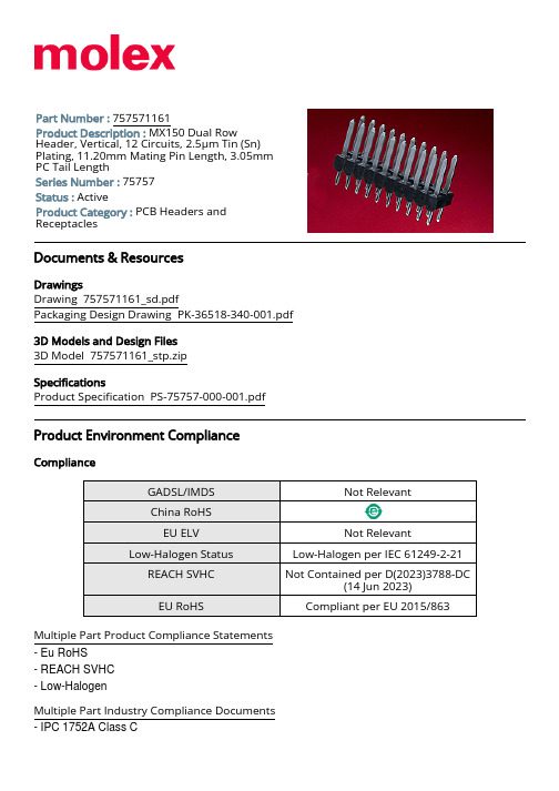
Breakaway Circuits (Loaded) Circuits (maximum)
Color - Resin Durability (mating cycles max)
First Mate / Last Break Glow-Wire Capable Guide to Mating Part
Multiple Part Industry Compliance Documents - IPC 1752A Class C
- IPC 1752A Class D - Molex Product Compliance Declaration - IEC-62474 - chemSHERPA (xml) EU RoHS Certificate of Compliance
Specifications Product Specification PS-75757-000-001.pdf
Product Environment Compliance
Complian RoHS
EU ELV Low-Halogen Status
REACH SVHC
Shrouded Temperature Range - Operating
Termination Interface Style
Solder Process Data
Max-Duration Lead-Free Process Capability
Max-Cycle Max-Temp
None Brass
3.50 x 6.00mm dual row grid PCB Header
MX150 Sealed and Unsealed Connector System MX150 822350702423
AC 马达用驱动 使用说明书

AC马达用驱动使用说明书i Series资料号NTO-C120-2首先,衷心感谢您购买使用本公司的产品。
为了更好的使用本产品,请您在使用之前,认真阅读使用说明书,正确使用本产品。
如果使用错误,会影响到正常的运行操作,或导致寿命低下,发生故障等问题。
使用错误会出现非常危险的状况,有导致死亡或重伤的危险。
使用错误会出现非常危险的状况,有导致中度受伤或轻伤的危险。
或导致物质损失。
通电或运行中,不要碰触端子台。
没有做过绝缘处理,会导致触电。
防止火灾驱动安装在没有孔(不要碰触驱动的降温装置等的背面)不燃性壁处。
不能安装在可燃物或或可燃物附近,易导致火防止破损各端子上只能使用使用说明书上规定的电压。
否则易破损制品需要安装在能够承受其重量的地方,请参照使用说明书安装。
配线正确连接。
否则会造成马达逆旋转。
试运行调整调整各参数。
不同的机械会产生不同的运动。
使用方法键,根据机能设定状态有输出不停止时,需要准备紧急停止回路(电源切断或紧急停止用机械刹车等)本制品的过电流保护机能,马达的过热保护不起作用时。
建议通过外部热,异常时的处置为防止驱动出现故障时,机械,装置不会处于危险状态,请设置非常刹车等安全保护装置。
保守点检・部品的交換不要对驱动的控制回路进行绝缘电阻测定。
会造成故障。
废弃【目录】1.警告表示 (6)2.名牌 (6)3.适用马达 (7)4.形式 (7)5.规格【0.75KW】 (7)6.规格【0.4KW】 (8)7.驱动规格【共通事项】 (8)8.环境条件 (9)9.标准连接图 (9)10.各部の名称 (10)11.接口 (10)12.电源端子 (11)13.马达动力端子 (11)14.输入输出端子 (12)15.安装 (13)16.操作方法 (14)17.外形图 (15)18.表示器の规格 (16)19.参数设定项目 (16)20.保护(警报)规格 (25)21.速度指令 (29)22.警报指令 (32)23.运行指令 (32)24.正逆转指令 (33)25.选择关闭器 (34)26.设置方法 (34)27.简单设置方法 (35)28.制品保证について (35)29.问题解答 (37)形式最大适用モータ输入规格输入规格输出规格图、触电、火灾的危险。
philips Micro System MC150 使用说明

Micro System MC150目錄一般事項環保說明 (5)隨機配件 (5)安全須知 (5)準備工作背面連接..............................................................6–7使用遙控器之前 (7)更換遙控器電池(鋰電池 CR2025) (7)控制鍵主機及遙控器上的控制鍵 (8)基本功能開機 (9)省電自動待機 (9)調節音量與音效 (9)光碟操作播放光碟 (10)選擇不同的曲目 (10)在一首曲目中尋找一個段落 (10)不同的播放模式:重複(Repeat)與亂序(Shuffle)播放 (11)編輯曲目播放清單 (11)查看曲目播放清單 (11)刪除曲目播放清單 (11)電台接收調諧選台 (12)預設電台 (12)選擇預設電台 (12)磁帶機操作/錄音磁帶播放 (13)關於錄音的一般說明 (13)CD 同步播放及錄音....................................13-14從收音機錄音 (14)維護保養 (14)時鐘/計時器設定時鐘 (15)查看時鐘 (15)設定計時器 (15)開啟與關閉計時器(TIMER) (15)開啟與關閉睡眠計時器(SLEEP) (16)技術規格 (16)故障排除.....................................................17-18一般事項環保說明我們已把多餘的包裝材料省掉。
並盡量使包裝物容易地分為如下三種材料﹕紙板 (紙箱)、聚苯乙烯泡沫塑料 (減震) 和聚乙烯 (包裝袋和保護性泡沫膠紙)。
若由專業公司進行拆卸,您這台產品中含有某些材料可再循環使用。
在處理這些廢棄的包裝材料、耗盡電池及舊設備時,請遵守當地的有關法規隨機配件–揚聲器音箱一對–遙控器連電池–MW 環形天線安全須知●在操作本機之前,應先確定本機銘牌上的操作電壓 (或者電壓選擇器旁所註明的電壓) 與您當地的電源電壓是否相同。
OTM1250E3CM110V 电机控制开关产品说明书

OTM1250E3CM110V
Product Net Height Product Net Depth / Length Product Net Weight
Technical
Rated Operational Current AC-21A (Ie)
Rated Operational Current AC-22A (Ie)
55 kg 6417019462509
Q EC000216 - Switch disconnector EC000216 - Switch disconnector EC000216 - Switch disconnector 4. Large Equipment (Any External Dimension More Than 50 cm)
Front operated Base mounting
3 Front IP20
Open
1SCC303036D0202
Certificates and Declarations (Document Number)
Declaration of Conformity - CE
1SCC303037D0201
12 kV
1000 V
1000 V
for 1 s 50 kiloampere rms
110 ... 125 V AC/DC
29 W 3
Black Direct mounted handle Mechanism at the End of the Switch
Standard
Top In - Bottom Out, Bottom In - Top Out
OTM1250E3CM110V
- 1、下载文档前请自行甄别文档内容的完整性,平台不提供额外的编辑、内容补充、找答案等附加服务。
- 2、"仅部分预览"的文档,不可在线预览部分如存在完整性等问题,可反馈申请退款(可完整预览的文档不适用该条件!)。
- 3、如文档侵犯您的权益,请联系客服反馈,我们会尽快为您处理(人工客服工作时间:9:00-18:30)。
℃
TJ
150
℃
Tstg
-55~+150
℃
焊接温度
TLED
260℃,10 秒
注:(1)、VM 代表 VM1 和 VM2,1 通道代表 FORWARD 和 BACKWARD 通道,2 通道代表 RIGHT 和 LEFT 通道。
(2)、不同环境温度下的最大功耗计算公式为: PD=(150℃-TA)/θJA
功能框图
13 VDD
LDO
带隙基准电路
振荡器
时序控制
2 SI 放大器
解码电路
逻 辑 电 路
14 VI1
15 VO1
过热保护电路
16 VI2 1 VO2
AGND 4
12
VM1
栅
驱
动
FORWARD 11
电
路
PGND
VM1
栅
驱
动
BACKWARD 10
电
路
PGND 9
TURBO 3
VM2 5
栅
驱
动
RIGHT 6
重庆中科芯亿达电子有限公司
Rev1.1
深办:深圳市南山区桃源路田厦金牛广场 A 座 2610 室
2016-04-25 电话:0755-26099570
传真:0755-26895685
5
SinotechMixic Electronics Co.,LTD
典型应用线路图
C2
向左
58(W1)
向左
向右
64(W1)
向右
重庆中科芯亿达电子有限公司
Rev1.1
深办:深圳市南山区桃源路田厦金牛广场 A 座 2610 室
2016-04-25 电话:0755-26099570
传真:0755-26895685
3
SinotechMixic Electronics Co.,LTD
传真:0755-26895685
4
SinotechMixic Electronics Co.,LTD
MX1508RX2
电特性参数表
(TA=25℃, VM =6.5V 除非另有规定)
参数
符号 条件
电源参数
VM 待机电流
IVMST
功 率 管 导通内阻
1 通道导通内阻
IO=±200mA VM1=6.5V TA=25℃ RON1 IO=±1000mA VM1=6.5V TA=25℃
道。
(2)、该芯片内置了温度保护电路,芯片的最高结温限制在 150℃,受封装散热能力的限制,最大持续
输出电流受到环境温度影响,表格中的值为 25℃环境下的推荐值。根据不同环境温度下最大功率的计算公
式可以计算出,夏天环境温度升到 40℃,持续电流输出能力比 25℃下降 7%。冬天环境温度降低到 10℃,
PCB 设计时,必须确保电路板的高频部分尤其是天线部分远离电机,否则电路易受到电机噪声的影响, 造成误码。此外,电机两端必须跨接 104 电容,否则电路极易受到电机噪声干扰,出现接收距离下降、误 码等现象。
重庆中科芯亿达电子有限公司
Rev1.1
深办:深圳市南山区桃源路田厦金牛广场 A 座 2610 室
五功能马达驱动电路 MX1508RX2
MX1508RX2
特性
低待机电流 (465uA) 低导通内阻 MOSFET 功率开关管
— 采用 MOS 工艺设计功率管 — 1 通道 1000 毫安功率管内阻 0.38 欧姆 — 2 通道 800 毫安功率管内阻 0.46 欧姆 内部集成续流二极管 — 无需外接续流二极管 高度集成方案,集成 RX2 芯片和两个马达驱动 内置 2.5V 稳压 LDO 电路 内置带迟滞效应的过热保护电路 (TSD)
该芯片具备较宽的工作电压范围(VM 端供电从 2V 到 8V),可覆盖 2 节干电池至 5 节干电池的应用。
单通道工作时,左转/右转通道用于驱动转向电 机,最大持续输出电流达到 1.35A,最大峰值输出电 流达到 2A。前进/后退通道用于驱动前进后退电机, 最大持续输出电流达到 1.45A,最大峰值输出电流达 到 2A;双通道同时工作时,左转/右转通道持续输 出 0.8A 的情况下,前进/后退通道能持续输出 1.2A。
该电路为功率器件,本身具备一定内阻,电路 的发热与负载电流、功率管导通内阻以及环境温度 密切相关。电路设计有芯片级温度检测电路,实时 监控芯片内部发热,当芯片内部温度超过设定值时, 产生功率管关断信号,关闭负载电流,避免因异常 使用导致的温度持续升高,进而造成塑料封装冒烟、 起火等严重安全事故。芯片内置的温度迟滞电路, 确保电路恢复到安全温度后,才允许重新对功率管 进行控制。
L1
C6
R2
Q1 C2712 R1
C5
C3 C4
R9=2.2M
M
左转/右转马达
M
C10=332P
2300源端 要接芯片 PGND, 不要就近 接AGND
1
R8=2.2K
2
2300
3
4
VO2 SI TURBO AGND
5 VM2
6 RIGHT
7 LEFT
8 PGND
VI2 16 VO1 15 VI1 14 VDD 13 VM1 12 FORWARD 11 BACKWARD 10 PGND 9
2016-04-25 电话:0755-26099570
传真:0755-26895685
1
SinotechMixic Electronics Co.,LTD
MX1508RX2
引脚排列
1 VO2 2 SI 3 TURBO 4 AGND 5 VM2 6 RIGHT 7 LEFT 8 PGND
持续电流输出能力比 25℃提高 6%。
(3)、通过加宽功率地、功率电源、输出端的 PCB 走线,增大散热面积能改善电流输出能力。
重庆中科芯亿达电子有限公司
Rev1.1
深办:深圳市南山区桃源路田厦金牛广场 A 座 2610 室
2016-04-25 电话:0755-26099570
VO2 SI TURBO AGND
470P
2.2M
5 VM2
6 RIGHT
C11=0.1uF
C13=0.1uF-100uF
前进/后退马达 M
7 LEFT
8 PGND
C10=332P 2300源端 要接芯片 PGND, 不要就近 接AGND
M 左转/右转马达
M
重庆中科芯亿达电子有限公司
Rev1.1
深办:深圳市南山区桃源路田厦金牛广场 A 座 2610 室
典型应用图
VI2 16 VO1 15 VI1 14 VDD 13 VM1 12 FORWARD 11 BACKWARD 10 PGND 9
R4
L2
C1
R3
R7 R5=2.2K
C9 C8=0.1uF C7
C4 C3
R1
R9=2.2M
Q1 C2712 C5
C2
R2
C6
L1
1
R8=2.2K
2
2300
3 4
功能键组合及译码结果详见下表。
功能键
功能码数(n)
译码结果
4(W2)
结束码
前进
10(W1)
前进
前进+加速
16(W1)
前进
加速
22(W1)
加速
加速+前进+向左
28(W1)
前进和向左
加速+前进+向右
34(W1)
前进和向右
后退
40(W1)
后退
后退和向右
46(W1)
后退和向右
后退和向左
52(W1)
后退和向左
功率电源电压
VM
2
--
8
V
TA=25℃
1 通道
IOUT1
独立工作持续输出电流
2 通道
IOUT2
TA=25℃
1 通道
IOUT1
同时工作持续输出电流
2 通道
IOUT2
1.45 1.35
A 1.2 0.8
注: (1)、VM 代表 VM1 和 VM2,1 通道代表 FORWARD 和 BACKWARD 通道,2 通道代表 RIGHT 和 LEFT 通
电
路
PDNG
VM2
栅
驱
动
LEFT 7
电
路
PGND
8
重庆中科芯亿达电子有限公司
Rev1.1
深办:深圳市南山区桃源路田厦金牛广场 A 座 2610 室
2016-04-25 电话:0755-26099570
传真:0755-26895685
2
SinotechMixic Electronics Co.,LTD
应用范围
2-5 节 AA/AAA 干电池供电的玩具马达驱动 2-5 节镍-氢/镍-镉充电电池供电的玩具马达驱
动 1-2 节锂电池供电的马达驱动
订购信息
产品型号 MX1508RX2
封装 SOP16
工作温度 -20℃ ~ 85℃
概述
MX1508RX2 是为遥控汽车等玩具设计的专用单 芯片解决方案,该芯片将传统方案的 RX2 接收解码 芯片以及马达驱动芯片整 合为单一芯片。 芯片内部 集成两路 H 桥驱动电路,可同时驱动转向电机以及 前进后退电机。
TA 表示电路工作的环境温度,θJA 为封装的热阻。150℃表示电路的最高工作结温。 (3)、电路功耗的计算方法: P =I2xR
其中 P 为电路功耗,I 为持续输出电流,R 为电路的导通内阻。电路功耗 P 必须小于最大功耗 PD
