AccoTEST硬件单板及编程- QVM
NI sbRIO-9637单板RIO OEM设备规格说明说明书
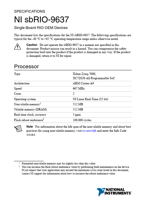
SPECIFICA TIONSNI sbRIO-9637Single-Board RIO OEM DevicesThis document lists the specifications for the NI sbRIO-9637. The following specifications are typical for the -40 °C to +85 °C operating temperature range unless otherwise noted.Caution Do not operate the sbRIO-9637 in a manner not specified in thisdocument. Product misuse can result in a hazard. You can compromise the safetyprotection built into the product if the product is damaged in any way. If the productis damaged, return it to NI for repair.ProcessorType Xilinx Zynq-7000,XC7Z020 All Programmable SoC Architecture ARM Cortex-A9Speed667 MHzCores2Operating system NI Linux Real-Time (32 bit)Nonvolatile memory1512 MBV olatile memory (DRAM)512 MBReal-time clock, accuracy 5 ppmFlash reboot endurance2100,000 cyclesNote For information about the life span of the nonvolatile memory and about bestpractices for using nonvolatile memory, visit /info and enter the Info CodeSSDBP.1Formatted nonvolatile memory may be slightly less than this value.2You can increase the flash reboot endurance value by performing field maintenance on the device.If you expect that your application may exceed the maximum cycle count listed in this document, contact NI support for information about how to increase the reboot endurance value.Operating SystemNote For minimum software support information, visit /info and enter theInfo Code swsupport.Supported operating system NI Linux Real-Time (32-bit)Minimum software requirementsApplication softwareLabVIEW LabVIEW 2015,LabVIEW 2015 Real-Time Module,LabVIEW 2015 FPGA ModuleEclipse Edition 2014C/C++ Development Tools forNI Linux Real-Time3Driver software NI CompactRIO Device Drivers August 2015 Reconfigurable FPGAType Xilinx Zynq-7000,XC7Z020 All Programmable SoCNumber of logic cells85,000Number of flip-flops106,400Number of 6-input LUTs53,200220Number of DSP slices(18 x 25 multipliers)Available block RAM560 KBNumber of DMA channels16Number of logical interrupts32Network/Ethernet PortNumber of interfacesFront Panel Ethernet 1 (Eth0)3C/C++ Development Tools for NI Linux Real-Time is an optional interface for C/C++programming of the sbRIO-9637 processor. Visit /info and enter Info Code RIOCdev for more information about the C/C++ Development Tools for NI Linux Real-Time.2| | NI sbRIO-9637 SpecificationsNetwork interface10Base-T, 100Base-TX, and1000Base-T Ethernet4Compatibility IEEE 802.3Communication rates10 Mbps, 100 Mbps,1000 Mbps auto-negotiated, half-/full-duplex Maximum cabling distance100 m/segmentRS-232 (DTE) Serial PortNumber of interfacesOnboard RS-232 2 (Serial1, Serial2)Baud rate support ArbitraryMaximum baud rate230,400 bpsData bits5, 6, 7, 8Stop bits1, 2Parity Odd, Even, Mark, SpaceFlow control RTS/CTS, XON/XOFF, DTR/DSR, NoneRS-485 Serial PortNumber of interfacesOnboard RS-485 1 (Serial3)Maximum baud rate460,800 bpsData bits5, 6, 7, 8Stop bits1, 1.5, 2Parity Odd, Even, Mark, SpaceFlow control XON/XOFFWire mode4-wire, 2-wire, 2-wire autoIsolation voltage, port to earth ground None4For revision D and earlier, 1000Base-T Ethernet link and communication is not guaranteed for the Ethernet port below -20 °C. If you expect ambient temperatures below -20 °C, NI recommendsusing a 10/100 network infrastructure or assigning 10/100Mbps communication speeds to theEthernet Adapter in NI Measurement & Automation Explorer (MAX).NI sbRIO-9637 Specifications| © National Instruments| 3Embedded CANNumber of interfacesOnboard CAN 1 (CAN0)Onboard CAN transceiver NXP PCA82C251TMaximum baud rate 1 MbpsMinimum baud rate10 kbpsUSB PortNumber of interfacesFront Panel USB Host 1 (USB0)Compatibility USB 2.0, Hi-SpeedMaximum data rate480 Mb/sMaximum front panel USB current900 mASD Card SlotNumber of interfacesFront Panel SD 1 (SDIO0)Supported Standards SD, SDHC5Front Panel SD ThroughputRead12.0 MB/s maximumWrite9.0 MB/s maximum3.3 V Digital I/O on 50-Pin IDC Connector Number of DIO channels28Maximum tested current per channel±3 mAInput logic levelsInput low voltage, V IL-0.3 V minimum; 0.8 V maximum Input high voltage, V IH 2.0 V minimum; 5.25 V maximum5Both standard SD and microSD interfaces are supported.4| | NI sbRIO-9637 SpecificationsOutput logic levelsOutput high voltage, V OH2.4 V minimum;3.45 V maximumwhen sourcing 3 mA0.0 V minimum; 0.4 V maximumOutput low voltage, V OLwhen sinking 3 mAAnalog Input CharacteristicsNumber of channels16 single-ended or 8 differentialADC resolution16 bitsMaximum aggregate sampling rate200 kS/sInput range±10 V, ±5 V, ±2 V, ±1 VMaximum working voltage (signal + common mode)10 V range±11 V5 V range±10.5 V2 V range±9 V1 V range±8.5 VInput impedancePowered on> 1 GΩ in parallel with 100 pFPowered off/overload 2.3 kΩ minimumOvervoltage protectionPowered on±25 V, for up to 2 AI pinsPowered off±15VAI accuracyNI sbRIO-9637 Specifications| © National Instruments| 5Gain drift 12 ppm of reading/°C Offset drift 4 ppm of range/°C AI noise10 V range 200 μVrms 5 V range 105 μVrms 2 V range 45 μVrms 1 V range 30 μVrmsINL ±64 ppm of range, maximum DNLNo missing codes guaranteed CMRR, DC to 60 Hz -80 dB Input bandwidth (-3 dB)540 kHz, typical Settling error (multichannel scanning)±60 ppm step size, typical Crosstalk (10 kHz)-70 dBTypical performanceFigure 1. Common Mode Rejection Ratio versus FrequencyC M R R (d B )Frequency (Hz)6 | | NI sbRIO-9637 SpecificationsFigure 2. Normalized Signal Amplitude versus Frequency–8–7–6–5–4–3–2–101N o r m a l i z e d S i g n a l A m p l i t u d e (d B )Frequency (Hz)Figure 3. Settling Error versus Source ImpedanceE r r o r (p p m o f S t e p S i z e )Source Impedance (Ω)10010001000010000010000010000100010010Analog Output CharacteristicsNumber of channels 4DAC resolution16 bitsNI sbRIO-9637 Specifications | © National Instruments | 7Maximum update rate6336 kS/sRange±10 VOverrange operating voltageMinimum10.3 VTypical10.6 VMaximum10.9 VOutput impedance0.4 Ω typicalCurrent drive±3 mA/channel maximumProtection Short-circuit to groundPower-on state70 VAO accuracyGain drift23 ppm of reading/°COffset drift 5.4 ppm of range/°CINL±194 ppm of range, maximumDNL±16 ppm of range, maximumCapacitive drive 1.5 nF, typicalSlew rate 3.7 V / μsec, typicalSettling time (100 pF load to 320 μV)FS step50 μs2 V step12 μs0.2 V step9 μs6This is the maximum update rate when running one AO channel in a loop with the FPGA top-level clock set to 40 MHz.7When the analog output initializes, a voltage glitch occurs for about 20 μs, peaking at 1.3 V,typical.8Range is 5 V.8| | NI sbRIO-9637 SpecificationsCMOS BatteryNote The battery is user-replaceable. The NI sbRIO device ships with a BR1225coin cell battery from RAYOV AC, which is industrial-rated. Ensure that powerremains connected to the NI sbRIO device while you replace the battery so thattime-keeping is not disrupted. Refer to the Battery Replacement and Disposalsection for information about replacing the battery.10 yearsTypical battery life with power applied topower connectorTypical battery life in storage at 55 °C 2.5 years9Power Outputs on 50-Pin IDC ConnectorCaution This output is protected by a fuse. Exceeding the power limits may causethis fuse to open.+5 V power outputOutput voltage 5 V ±5%Maximum current 1.5 AMaximum ripple and noise50 mVPower RequirementsThe NI sbRIO device requires a power supply connected to the power connector. Refer to the Powering On the NI sbRIO Device section in the NI sbRIO-9637 Getting Started Guide on /manuals for information about connecting the power supply.Caution Exceeding the power limits may cause unpredictable device behavior.Recommended power supply55 W, 30 VDC maximumPower supply voltage range9 VDC to 30 VDCReversed-voltage protection30 VDCPower consumption26 W maximum9Battery life may drop dramatically in extreme temperatures.NI sbRIO-9637 Specifications| © National Instruments| 9EnvironmentalCaution Clean the sbRIO-9637 with a soft, nonmetallic brush. Make sure that thedevice is completely dry and free from contaminants before returning it to service.-40 °C to 85 °C10Local ambient operating temperature neardevice (IEC 60068-2-1, IEC 60068-2-2)Maximum reported onboard sensor temperatureCPU/FPGA temperature98 °CPrimary System temperature85 °CSecondary System temperature85 °CTable 1. Component Maximum Case TemperatureThe sbRIO-9637 includes three onboard temperature monitoring sensors to simplify validation of a thermal solution by indicating thermal performance during validation and deployment. The sensors measure the CPU/FPGA junction temperature and printed circuit board temperatures that can be used to approximate the primary and secondary side local ambient temperatures. This approach is called digital validation. Alternatively, the traditional analog approach using thermocouples can be used to validate thermal performance. The digital approach is more accurate for determining the performance of the CPU/FPGA but is more conservative for determining the local ambient temperatures. NI recommends using digital validation.For digital validation, ensure that the reported CPU/FPGA, reported Primary System, and reported Secondary System temperatures do not exceed any of the maximum temperatures listed in this document. Thermal validation is complete if the reported temperatures are within10If you expect ambient temperatures below -20 °C, NI recommends using a 10/100 network infrastructure or assigning 10/100Mbps communication speeds to the Ethernet Adapter in NI MAX.Refer to the Network/Ethernet Port section of this document for more information.11Use digital approach to ensure the on-chip temperature reading is below 98°C.10| | NI sbRIO-9637 Specificationsspecifications. For more information about how to access the onboard sensors, visit / info and enter the Info Code sbriosensors. If the reported Primary System temperature or reported Secondary System temperature exceed the maximum temperatures listed in this document then analog validation may be used for further verification.For analog validation, measure the local ambient temperature by placing thermocouples on both sides of the PCB, 5 mm (0.2 in.) from the board surface. Avoid placing thermocouples next to hot components such as the CPU/FPGA or near board edges, which can cause inaccurate temperature measurements. In addition to the local ambient temperature, the case temperature of the components should not exceed the recommended maximum case temperature.Note Some systems may require a heat sink or air flow to remain within themaximum allowed temperature ranges. You can mount the Thermal Kit forNI sbRIO-9607/9627/9637 (153901-02) heat spreader on the NI sbRIO device.Note The NI sbRIO device thermal performance is greatly influenced by severalfactors, including resource utilization, mounting, and adjacent power dissipation.These factors can substantially affect the achievable external ambient temperature atwhich the maximum local and reported temperatures are reached. NI recommendsadditional thermal design to remain within the maximum allowed temperatureranges. For information about and examples of environmental and design factors thatcan affect the thermal performance of NI sbRIO systems, visit /info and enterthe Info Code sbriocooling. For device-specific guidelines about enablingproper thermal design, refer to the NI sbRIO-9637 User Manual on /manuals.-40 °C to 85 °CStorage temperature(IEC 60068-2-1, IEC 60068-2-2)Operating humidity (IEC 60068-2-78)10% RH to 90% RH, noncondensing Storage humidity (IEC 60068-2-78)5% RH to 95% RH, noncondensing Maximum altitude5,000 mPollution Degree (IEC 60664)2The NI sbRIO device is intended for indoor use only.Physical CharacteristicsWeight128.7 g (4.540 oz)NI sbRIO-9637 Specifications| © National Instruments| 11Safety VoltagesConnect only voltages that are below these limits.V terminal to C terminal30 VDC maximum, Measurement Category I Measurement Category I is for measurements performed on circuits not directly connected to the electrical distribution system referred to as MAINS voltage. MAINS is a hazardous live electrical supply system that powers equipment. This category is for measurements of voltages from specially protected secondary circuits. Such voltage measurements include signal levels, special equipment, limited-energy parts of equipment, circuits powered by regulated low-voltage sources, and electronics.Caution Do not connect the sbRIO-9637 to signals or use for measurements withinMeasurement Categories II, III, or IV.Environmental ManagementNI is committed to designing and manufacturing products in an environmentally responsible manner. NI recognizes that eliminating certain hazardous substances from our products is beneficial to the environment and to NI customers.For additional environmental information, refer to the Minimize Our Environmental Impact web page at /environment. This page contains the environmental regulations and directives with which NI complies, as well as other environmental information not included in this document.Waste Electrical and Electronic Equipment (WEEE)EU Customers At the end of the product life cycle, all NI products must bedisposed of according to local laws and regulations. For more information abouthow to recycle NI products in your region, visit /environment/weee.Battery Replacement and DisposalBattery Directive This device contains a long-life coin cell battery. If you need toreplace it, use the Return Material Authorization (RMA) process or contact anauthorized National Instruments service representative. For more information aboutcompliance with the EU Battery Directive 2006/66/EC about Batteries andAccumulators and Waste Batteries and Accumulators, visit /environment/batterydirective.12| | NI sbRIO-9637 Specifications电子信息产品污染控制管理办法(中国RoHS)中国客户National Instruments符合中国电子信息产品中限制使用某些有害物质指令(RoHS)。
AccoTEST硬件单板及编程-----AWG函数

Make Testing More ValuableMake Testing More Valuable AccoTEST硬件单板及编程(1)---AWG函数Make Testing More ValuableSTSAWGCreateSineData(double *awgData ,UINT dataNumber , double waveCycles , double Vpp , double DCOffset , double phase );STSAWGCreateSineData()Exampledouble awg_pattern[1000]={0.0};STSAWGCreateSineData(&awg_pattern[0],100,1,5,0,180);awgDataA double pointer used to store the first address of AWG waveform data.dataNumberThe data length of AWG waveform.waveCyclesThe cycle count of a sine wave.VppThe peak-to-peak value of a sine waveform.DCOffsetThe DC bias of a sine waveform.PhaseThe phase of a sine wave.Make Testing More Valuable STSAWGCreateTriangleData()STSAWGCreateTriangleData(double *awgData, UINT dataNumber, double waveCycles, double Vpp, double DCOffset, double phase);awgDataA double pointer used to store the first address of AWG waveform data.dataNumberThe data length of AWG waveform.waveCyclesThe cycle count of a triangular wave.VppThe peak-to-peak value of a triangular waveform.DCOffsetThe DC bias of a triangular waveform.PhaseThe phase of a triangular wave.Exampledouble awg_pattern[1000]={0.0};STSAWGCreateTriangleData(&awg_pattern[0],100,4,5,0,0);Make Testing More ValuableSTSAWGCreateSquareData()awgDataA double pointer used to store the first address of AWG waveform data.dataNumberThe data length of AWG waveform.waveCyclesThe cycle count of a square wave.VppThe peak-to-peak value of a square waveform.DCOffsetThe DC bias of a square waveform.dutyCycleThe duty cycle of square waveform.Exampledouble awg_pattern[1000]={0.0};STSAWGCreateSquareData(&awg_pattern[0],100,4,5,0,50);STSAWGCreateSquareData(double *awgData , UINT dataNumber , double waveCycles , double Vpp , double DCOffset , double dutyCycle );Make Testing More ValuableSTSAWGCreateRampData()awgDataA double pointer used to store the first address of AWG waveform data.dataNumberThe data length of AWG waveform.waveCyclesThe cycle count of a ramp wave.startValueThe start value of ramp waveform.stopValueThe stop value of ramp waveform.Exampledouble awg_pattern[1000]={0.0};STSAWGCreateRampData(&awg_pattern[0],100,1,1,5);STSAWGCreateRampData(double *awgData , UINT dataNumber , double waveCycles , double startValue , double stopValue );Make Testing More ValuableSTSEnableAWG()ExampleFOVI VCC(0);STSEnableAWG(&VCC);STSEnableAWG (Floating VI1, Floating VI2, Floating VI3, ……);Floating VI1, Floating VI2, Floating VI3, ……Fill out the VI source name needed to be enabled, Only FPVI10 and FOVI100 can be available.A total of 32 sources can be added.RemarksEnable the synchronization of AWG.Make Testing More ValuableSTSEnableMeas()ExampleFOVI VCC(0);FPVI10 VIN_VOUT(0);STSEnableMeas(&VCC,&VIN_VOUT);STSEnableMeas (Floating VI1, Floating VI2, Floating VI3, ……);Floating VI1, Floating VI2, Floating VI3, ……Fill out the VI source name needed to be enabled, Only FPVI10 , FOVI100 and QVM can be available.A total of 32 sources can be added.RemarksThis function is used to enable synchronous measurement.Make Testing More ValuableSTSAWGRun()ExampleStsAWGRun();STSAWGRun (delayTime );delayTimeSet delay time. An INT variable. Ranges:0ms ~ 60000ms.After AWG outputs the specified delayTime, the system will allow the functions next to STSAWGRun() to be executed.Notes: Normally leave the “delay time”blank. It means that only after the AWG scanning and measurement are completed, the system will allow the functions next to STSAWGRun() to be executed.RemarksThis function is used to make the synchronous of AWG activate.Make Testing More ValuableSTSAWGRunTriggerStop()Examplefovi1.SetMeasVTrig(2,TRIG_FALLING);fovi0.MeasureVI(500,20,MEAS_AWG);fovi1.MeasureVI(500,20,MEAS_AWG);STSEnableAWG(&fovi0); //enable synchronous AWG for fovi0.STSEnableMeas(&fovi0, &fovi1); //Enable synchronous measurement for fovi0 and fovi1.STSAWGRunTriggerStop(&fovi1, &fovi1, &fovi0);//fovi0 and fovi1 will terminate once the trigger event came into effect.STSAWGRunTriggerStop(FloatingVI *viTrigger , FloatingVI *stopVi1, FloatingVI *stopVi2= NULL, …, FloatingVI *stopVi16= NULL);FloatingVI *viTriggerThe name of VI source that is used to set trigger event. The VI source is consistent with the source used in SetMeasVTrig() or SetMeasITrig() function.FloatingVI *stopVi1, FloatingVI *stopVi2, …, FloatingVI *stopVi16The name of VI source that will terminate once the trigger event came into effect. Up to 16 VI source’s name can be added.RemarksOnce the trigger event came into effect, the AWG waveform will immediately terminate.Make Testing More Valuable Difference between STSAWGRun() and STSAWGRunTriggerStop()STSAWGRun() STSAWGRunTriggerStop()Make Testing More ValuableMake Testing More Valuable。
Testo 最新一代气流速度和空气质量仪测试仪说明书
Latest generation testo air velocity & IAQ probes with fixed cableInstruction manualContents Contents1About this document (3)2Safety and disposal (3)3System description (4)4Description of the instrument (5)4.1Hot wire probe, including temperature sensor (0635 1032) (5)4.2Vane probe (Ø 16 mm) (0635 9532) (6)4.3High-precision temperature/humidity probe up to +180°C (0636 9775) 64.4Lux probe (0635 0551) (7)4.5Turbulence probe (0628 0152) (7)4.6Laboratory flue probe (0635 1052) (8)5Commissioning (9)6Maintenance (9)6.1Maintaining the probes (9)6.1.1Cleaning the instrument (9)6.1.2Calibration (9)7Technical data (10)8Accessories and spare parts (13)1 About this document1About this document•The instruction manual is an integral part of the instrument.•Please read this instruction manual through carefully and familiarize yourself with the product before putting it to use.•Pay particular attention to the safety instructions and warning advice in order to prevent injury and damage to the product.•Keep this documentation to hand so that you can refer to it when necessary.•Always use the complete original instruction manual.•Hand this instruction manual on to any subsequent users of the product.2Safety and disposalSecurity•Only use the product properly, for its intended purpose, and within the parameters specified in the technical data. Do not apply any force. •Dangers may also arise from the systems being measured or the measuring environment: always comply with the locally valid safety regulations when carrying out measurements.•Do not carry out any contact measurements on uninsulated, live parts. •Do not store the product together with solvents. Do not use any desiccants. •Only carry out maintenance and repair work on this instrument which is described in the documentation. Follow the prescribed steps exactly when doing the work. Use only original spare parts from Testo.•Temperature information given on probes/sensors relates only to the measuring range of the sensor technology. Do not expose handles and feed lines to temperatures in excess of 50°C (122°F), unless they are expressly authorized for use at higher temperatures.•Do not operate the instrument if there are signs of damage on the housing or supply lines.33 System description4Disposal• At the end of its useful life, deliver the product to the separate collectionpoint for electric and electronic devices (observe local regulations) or return the product to Testo for disposal.•WEEE Reg. no. DE 753343523 System descriptionYou have acquired a probe, if applicable with additional probe-specific accessories.The probe can be directly connected to the testo 440 measuring instrument.You will find detailed information about how each of the probes works along with the testo 440 measuring instrument in the corresponding chapter of the instruction manual for the measuring instrument.4 Description of the instrument54 Description of the instrument4.1 Hot wire probe, including temperaturesensor (0635 1032)ApplicationIn conjunction with the testo 440, the hot wire probe is suitable for flow and humidity measurements in ventilation ducts. Structure1 Sensor with protective sleeve2 Probe adapter3 Telescope with scaling 4Cable 5 Connection plugCAUTIONDamage to sensor possible! - Do not touch sensor!- Close the protective sleeve after the measurement.Low flow velocities may result in greater measurement uncertainties during temperature and humidity measurement. The probe should be switched on outside a duct under the following conditions: Ambient temperature: 20°C Flow: approx. 0 m/s.Collapse the telescope after use and do not constrict with the cable.4 Description of the instrument64.2 Vane probe (Ø 16 mm) (0635 9532)ApplicationIn conjunction with the testo 440, the vane probe (Ø 16 mm) is suitable for flow measurements in ventilation ducts. Structure1 Probe head2 Telescope3 Telescope handle4 CableCAUTIONDamage to sensor possible! - Do not touch sensor!- Put the protective sleeve on after the measurement.Collapse the telescope after use and do not constrict with the cable. 4.3 High-precision temperature/humidityprobe up to +180°C (0636 9775)ApplicationIn conjunction with the testo 440, the high-precision temperature/humidity probe is used to measure humidity and temperature. Structure1 Probe head 2Sintered cap 3 Probe shaft 4 Handle 5 CableCAUTIONDamage to sensor possible! - Do not touch sensor!4 Description of the instrument74.4 Lux probe (0635 0551)ApplicationIn conjunction with the testo 440, the lux probe is used to determine the illuminance of workplaces. In general, the illuminance measurement of warm light or white LEDs is possible because these types of LED cover the whole spectral range of the human eye. The measurement of one-colour LEDs (e.g. blue LEDs) is not recommended. Structure1 Measuring sensor2 CableCAUTIONDamage to sensor possible! - Do not touch sensor!4.5 Turbulence probe (0628 0152)ApplicationIn conjunction with the testo 440, the turbulence probe is used for temperature and air pressure measurement. Structure1 Sensor2 Guard3 Probe shaft4 Handle5 Cable4 Description of the instrument8Damage to sensor possible! - Do not touch sensor!The probe contains sensitive components. Please handle the probe with care.4.6 Laboratory flue probe (0635 1052)ApplicationIn conjunction with the testo 440, the laboratory flue probe is used to determine flow velocities in laboratory fume cupboards. Structure1 Sensor2 Protective sleeve3 Button 4Handle 5 CableATTENTIONDamage to sensor possible! - Do not touch sensor!- Push the protective sleeve over the sensor after the measurement.The probe contains sensitive components. Please handle the probe with care.Low flow velocities may result in greater measurement uncertainty during temperature measurement!5 Commissioning95 CommissioningDisplaying readings✓Sensor is connected to the measuring instrument.Readings are displayed.6 Maintenance6.1 Maintaining the probes6.1.1 Cleaning the instrumentDo not use any aggressive cleaning agents or solvents; instead use mild household cleaning agents or soapy water.Always keep the connections clean and free from grease and other deposits.Clean the instrument and the connections with a damp cloth and dry them off.6.1.2 CalibrationThe probes are supplied with a factory calibration protocol as standard. Recalibration of the probes once every 12 months is recommended in many applications. This can be carried out by Testo Industrial Services (TIS) or othercertified service providers with the aid of easy-to-use service software. Please contact Testo for further information.7 Technical data107 Technical data• Adjustment conditions for flow probes:Adjustment in free jet Ø 350 mm, reference pressure 1013 hPa, based on testo reference Laser Doppler Anemometer (LDA). • Note for flow probes:Low flow velocities may result in greater measurement uncertainties during humidity and temperature measurement! • Note for humidity probes:Please do not use the humidity probes in condensing atmospheres. For continuous use in high-humidity ranges > 80% RH at ≤ 30°C for > 12 h > 60% RH at > 30°C for > 12 hplease get in touch with Testo Service or contact us via the Testo website.Hot wire probe, including temperature sensor (0635 1032) FeatureValueMeasuring range0 to +30 m/s -20 to +70°C 700 to 1100 hPaAccuracy(at 22°C, ± 1 digit)± (0.03 m/s + 4% of m.v.) (0 to 20 m/s) ± (0.5 m/s + 5% of m.v.) (20.01 to 30 m/s) ± 0.5°C (0 to +70°C) ± 3 hPa Resolution0.01 m/s 0.1°C 0.1 hPaStorage temperature -20°C to +70°C Operating temperature -20°C to +70°C Protection class IP20DimensionsCable length: 1.7 mExtension length with telescope: 850 mm Ø probe head on the sensor: 9 mm Ø end of probe shaft: 12 mm Weight90 gDirectives, standards and testsEU Directive: 2014/30/EU7 Technical data11Vane probe (Ø 16 mm) (0635 9532) FeatureValue Measuring range0.6 to 50 m/s Accuracy(at 22°C, ± 1 digit)± (0.2 m/s +1% of m.v.) (0.6 to 40 m/s) ± (0.2 m/s +2% of m.v.) (40.1 to 50 m/s) Resolution0.1 m/s Storage temperature-10°C to +70°C Operating temperature-10°C to +70°C Protection classIP20 Dimensions Cable length: 1.7 mExtension length with telescope: 850 mmØ probe head: 16 mmØ end of probe shaft: 12 mmWeight 148 gDirectives, standards andtestsEU Directive: 2014/30/EUHigh-precision temperature/humidity probe up to +180°C (0636 9775) FeatureValue Measuring range-20 to +180°C 0 to 100% RH Accuracy(at 22°C, ± 1 digit)±0.5°C (-20 to 0°C) ±0.4°C (0.1 to +50°C) ±0.5°C (+50.1 to +180°C) Accuracy(at 25°C, ±1 digit) ±3% RH (0 to 2% RH) ±2% RH (2.1 to 98% RH)±3% RH (98.1 to 100% RH)Additional uncertainty- Long-term stability: ±1% RH / yearResolution 0.1°C0.1% RHTemperature coefficient type (k=1) ±0.03% RH/K (-20 to +50°C)type (k=1) ±0.06% RH/K (+50 to +180°C)Storage temperature -20 to 60°COperating temperature Handle: -5 to +50°CProbe head: -20 to +180°CProtection classIP207 Technical data12 FeatureValue Dimensions Cable length: 1.4 mOverall probe length: 420 mmProbe shaft length: 270 mmØ probe shaft: 12 mmWeight 255 gDirectives, standards andtestsEU Directive: 2014/30/EULux probe (0635 0551) FeatureValue Measuring range0 to 100,000 lux Accuracy(at 22°C, ±1 digit)DIN EN 13032-1 Appendix B; Class C according to DIN 5032-7 Resolution0.1 lux < 10,000 lux 1 lux ≥ 10,000 lux Storage temperature-20 to +50°C Operating temperature0 to +50°C Ambient humidityPreferred use: 20 to 80% RH DimensionsCable length: 1.4 m Housing: 110 x 55 x 22 mm Weight 110 g Directives, standards andtestsEU Directive: 2014/30/EUTurbulence probe (0628 0152)FeatureValue Measuring range 0 to +5 m/s0 to +50°C700 to 1100 hPaAccuracy (at 22°C, ± 1 digit) ± (0.03 m/s + 4% of m.v.) (0 to +5 m/s)± 0.5°C± 3 hPaResolution 0.01 m/s0.1°C0.1 hPaStorage temperature -20 to +60°COperating temperature0°C to +50°C8 Accessories and spare parts13 FeatureValue Dimensions Cable length: 1.4 mOverall probe length: 400 mmProbe shaft length: 195 mmWeight 250 gDirectives, standards andtestsEU Directive: 2014/30/EULaboratory flue probe (0635 1052) FeatureValue Measuring range 0 to +5 m/s0 to +50°C700 to 1100 hPaAccuracy (at 22°C, ± 1 digit) ± (0.02 m/s + 5% of m.v.) (0 to +5 m/s)± 0.5°C± 3 hPaResolution 0.01 m/s0.1°C 0.1 hPaStorage temperature -20 to +60°COperating temperature 0°C to +50°CDimensions Cable length: 1.4 mOverall probe length: 350 mmProbe shaft length: 195 mmWeight 230 gDirectives, standards andtestsEU Directive: 2014/30/EU8 Accessories and spare partsDescription Order no. Measuring stand with standard-compliant positioning of probes (including bag)0554 15900971 0455 en 03。
综合模块化航电(IMA)硬件单元

综合模块化航电(IMA)硬件单元1. 目的本技术标准规定(CTSO)适用于为综合模块化航电(IMA)硬件单元申请技术标准规定项目批准书(CTSOA)的制造人。
本CTSO 规定了综合模块化航电硬件单元为获得批准和使用适用的CTSO标记进行标识所必须满足的最低性能标准(MPS)。
2. 适用范围a. 本CTSO适用于自其生效之日起提交的申请。
本CTSO具体针对以下硬件单元:(1)硬件模块;(2)装载硬件模块的机柜或机架。
b. 符合本CTSO要求的硬件单元可用来支持功能CTSO设备或按照CCAR-21、23、25、27、29、33或35部批准的系统(例如,作为型号合格证组成部分批准的刹车系统)。
功能CTSO的批准和飞机级批准不在本CTSO的范围之内。
c. 附录3给出了硬件单元的相关术语。
d. 按本CTSO批准的综合模块化航电硬件单元,设计大改应获得CAAC的批准。
参见CCAR-21R3第21.313条。
3. 要求在本CTSO生效之日或生效之后制造并欲使用本CTSO标记进行标识的硬件单元,必须满足硬件单元最低性能标准。
本CTSO附录1给出了综合模块化航电硬件单元最低性能标准制定准则。
a. 功能:本CTSO适用于预期满足按本CTSO附录1准则制定的最低性能标准的设备。
本CTSO不针对预期执行的飞机级功能,而是为支持接收、处理和输出数据等通用功能的硬件提出环境鉴定试验要求。
获得本CTSO批准的硬件单元在加载相应软件程序时,也可能需要满足其他CTSO功能要求。
对于软件与硬件的组合,应使用适用的CTSO对其进行额外的CTSO功能批准。
设备或系统执行的未获得CTSO批准的功能,必须在装机过程中由局方评估和批准。
b. 功能限制:(1)本CTSO不适用于为目标发射器生成无线电频率信号的设备。
(2)本CTSO针对的软件功能仅限于支持电子件号和/或功能软件加载的软件。
c. 失效状态类别:失效状态类别取决于在特定飞机环境中执行的功能及其用途。
华为硬件信号质量与时序测试指导书
3.6.1时钟信号测试. . . . . . . . . . . . . . . . . . . . . . . . . . . . . . . . . . . . . . . . . . . . . . . . . . 8 3.6.1.1测试指标 . . . . . . . . . . . . . . . . . . . . . . . . . . . . . . . . . . . . . . . . . . . . . . . . . . . . . . . . . . . . . . . 8 3.6.1.2测试方法与测试重点 . . . . . . . . . . . . . . . . . . . . . . . . . . . . . . . . . . . . . . . . . . . . . . . . . . . . . 8
硬件模块单元测试报告-模板

硬件模块单元测试报告编制: 日期:审核: 日期: 批准: 日期:目录目录 (1)第一章概述 (3)1.1目的和范围 (3)1.2测试概述 (3)第二章测试资源及环境 (4)2.1 硬件配置 (4)2.2 测试设备清单 (4)2.3 测试环境 (4)2.4 测试方式 (4)第三章测试数据 (6)3.1 主控板测试 (6)3.1.1短路测试 (6)3.1.2直流电压、纹波测试 (6)3.1.3接口通讯信号测试 (8)3.1.3.1主控板与按键板打印部分 (8)3.1.3.2主控板与核心板 (8)3.1.3.3主控板与液晶屏 (8)3.1.3.4主控板与触摸屏 (9)3.1.3.5主控板与感光板 (10)3.1.3.6主控板对按键板指示灯部分检测信号 (10)3.1.3.8主控板与WIFI板 (10)3.1.4充电测试 (11)3.1.5电源转换效率测试 (11)3.1.5.1 5V电源转换效率测试 (11)2.1.5.2 +8V电源转换效率测试 (13)3.1.6 DC_DC带负载测试 (14)3.2 按键板测试 (15)3.2.1短路测试 (15)3.2.2直流电压、纹波测试 (15)3.2.3接口通讯信号测试 (15)3.2.3.1 按键板与打印机 (15)第一章概述1.1目的和范围本文描述H3硬件模块的测试方法和步骤, 本方案的来源是《H3硬件总体需求》和《H3硬件总体方案》适用范围是:1.2测试概述在硬件模块测试阶段, 测试人员根据细化后的方案进行集成测试, 测试的重点是接口, 主要包括以下几个方面:1.各个板卡接口和测试点电压纹波测试2.控制/检测信号逻辑状态分析第二章测试资源及环境2.1 硬件配置2.3 测试环境环境温度: 0-55℃;大气压力: 700hPa~1060hPa;相对湿度:15% ~ 95%, 非凝2.4 测试方式内部测试第三章测试数据3.1 主控板测试3.1.1短路测试3.1.3接口通讯信号测试3.1.3.1主控板与按键板打印部分3.1.3.2主控板与核心板3.1.3.3主控板与液晶屏3.1.3.4主控板与触摸屏3.1.3.5主控板与感光板3.1.3.8主控板与WIFI板3.1.4充电测试使用电源交流100~240Vac 50Hz/60Hz 使用内置锂电池 12.6V/2600mA3.1.6 DC_DC带负载测试3.2 按键板测试3.2.1短路测试3.2.3接口通讯信号测试3.2.3.1 按键板与打印机。
AccoTEST硬件单板与编程- DIO

Example: DIO dio(0);//定义第一块DIO为dio
dio.LoadPattern(0 , "XH00XH00");//行0 dio.LoadPattern(1 , "XH01XH01");//行1 dio.LoadPattern(2 , "XH00XH00");//行2 dio.LoadPattern(3 , "XH11XH11");//行3 dio.LoadPattern(4 , "XH00XH00");//行4 dio.LoadPattern(5 , "XH01XH01");//行5 dio.LoadPattern(6 , "XH10XH10");//行6
Example: dio.Init(); //Init the board of dio.
Connect()
Make Testing More Valuable
void Connect();
Remarks 接通数字部分所有8通道输出继电器。
Example: dio.Connect();//Connect all the output relays for 8channels.
Disconnect(带参数)
void Disconnect(unsigned short ch0,...)
Remarks 断开数字部分的所有8通道输出继电器。
Parameters Ch0:通道号,从0开始,取值范围0~7,以-1为结束符。
Example: dio0.Disconnect(0,1,2,-1);//只断开0、1、2通道的输出继电器
Make Testing More Valuable
AccoTEST硬件单板及编程- HVI1K

vrnghvi1k1000vhvi1k500vhvi1k200vhvi1k100virnghvi1k10mahvi1k1mahvi1k100uahvi1k10uahvi1k1uarelayswitchrelayon接通输出继电器relayoff断开输出继电器remarks设置hvi1k的状态包括工作模式恒压或恒流值电压量程或电流量程以及输出继电器状态
Make Testing More Valuable
GetMeasResult()
Example2: double adresult[100][SITENUM]={0}; hvi1k0.Set(FV, 600, HVI1K_1000V, HVI1K_1MA, RELAY_ON); delay_ms(10); hvi1k0.MeasureVI(MI, 100, 20);// sampleNumbe=100 for(int SITEID=0; SITEID<SITENUM; SITEID++) { for(int i=0; i<100; i++) { adresult[i][SITEID] = hvi1k0.GetMeasResult(SITEID, i); } } hvi1k0.Set(FV, 0, HVI1K_1000V, HVI1K_1MA, RELAY_OFF); delay_ms(1);
单板硬件调试报告
单板硬件调试报告一、引言本报告旨在描述和总结单板硬件调试的过程和结果。
在调试过程中,我们使用了一块STM32F103ZET6单片机作为目标控制器,并添加了一些外设电路。
本报告将详细描述所添加的外设电路和单板的硬件调试过程。
二、电路设计和材料清单本次调试使用的外设电路包括:LED指示灯、蜂鸣器、按键、LCD液晶显示屏。
我们在单片机的GPIO口连接了LED灯和按键,同时通过PWM 信号控制蜂鸣器的声音大小。
此外,LCD液晶显示屏通过SPI接口与单片机相连,用于显示相关信息。
三、硬件调试步骤1.检查电路连接:首先,我们对电路连接进行了检查,确保所有连接正确无误。
检查包括检查电源连接、信号线连接以及地线连接等。
确保电路连接正确会大大减少后续调试中可能出现的问题。
2.电源测试:接下来,我们进行了电源测试。
通过连接电源,我们检查了供电电压和电流。
确认供电电压和电流正常后,我们开始进行下一步调试。
3.I/O端口测试:为了验证单片机的I/O端口是否正常工作,我们将通过连接LED灯和按键来进行测试。
我们通过编写相应的程序,实现LED 灯的闪烁和按键的检测。
通过观察LED灯的闪烁和按键的检测情况,我们确认I/O端口正常工作。
4.蜂鸣器测试:接下来,我们进行了蜂鸣器的测试。
通过PWM信号,我们能够控制蜂鸣器的声音大小。
我们通过调整PWM信号的占空比,测试蜂鸣器的不同声音。
5.LCD液晶显示屏测试:最后,我们进行了LCD液晶显示屏的测试。
我们编写了测试程序,在屏幕上显示一些测试信息。
通过观察LCD屏幕上显示的内容,我们确认LCD显示正常。
四、实验结果和讨论经过以上调试步骤,我们成功地测试了单片机的各个外设电路。
LED 灯能够正常闪烁,按键能够正常检测,蜂鸣器能够通过PWM信号产生不同声音,LCD液晶显示屏能够正常显示信息。
通过本次调试,我们对单板硬件的基本功能进行了验证,确保了各个外设的正常工作。
同时,我们也发现了一些问题和改进的空间。
Quectel_EC20_R2.0_硬件设计手册_V1.2
e 3.5.2. 飞行模式 ......................................................................................................................... 29 fid 3.6. 电源设计 ................................................................................................................................ 29
10. 图 31 增加备注 3。
11. 增加射频信号线 Layout 参考指导(5.1.4 章节)。
12. 更新模块耗流数据(表 33)。
13. 增加 GNSS 耗流数据(表 34)。
14. 更新 7.3 章节中模块俯视图。
上海移远通信技术股份ຫໍສະໝຸດ 限公司2 / 83EC20 R2.0 硬件设计手册
目录
3.6.1. 管脚介绍 ......................................................................................................................... 29 3.6.2. 减少电压跌落.................................................................................................................. 30
STS 8200测试系统基础培训(1)-系统概述

总线插座
STS 8200 插件箱(后)
背板总线 通讯卡
模拟地
汇流条
背板总线通讯卡
插件箱(上)
插件箱(下)
注:拨码为00,有表贴电阻
注:拨码是01,没有表贴电阻
插件箱及电路板标识
原则上电路板按照插件箱上的标识放置
电缆标识-----接测试机
命名原则:电路板名称-电路板编号-插头编号 如下图:DVI-1-J1,即DVI1的第1个插头。
TWIN工作模式
TWIN_A STATION_B
TWIN_A CAGE_A
TWIN_A STATION_A TWIN_B STATION_B
TWIN_B CAGE_B
TWIN_B STATION_A
TWIN硬件配置
STS8200支持TWIN工作模式,实现方式如下: 1. 配置2块带表贴电阻总线接口卡(IF8001)且拨码均为00和00,上下笼子 各一块 2. 配置2套外电缆和2个测试盒。 3. 配置2套与电脑主机连接68芯的通信电缆 4. 配置2套与Handler连接62芯的通信电缆 5. 2套电脑主机
- 62芯TTL通讯电缆
注: 1)接插测试机通讯电缆,注意检查插座的针是否有弯曲变形,插 上后要拧紧固定螺钉 2)接插外电缆时要注意标识,不要插错电缆 3)68芯通讯电缆和CBIT128通讯电缆接头针脚较细,接插时需格 外注意 4)62芯TTL通讯电缆需根据Handler接口的PIN脚定义焊接完成
系统通讯
每块卡最多可支持四工位测试
接口采用TTL电平通讯 对每一工位提供8个分BIN信号
计算机
PC机用于运行STS 8200系统软件,并对整个系统运行进 行控制。PC机应不低于如下配置:
• • • • • 奔腾4 CPU 256M以上内存 40G硬盘 1024 x 768 彩色显示器 2个以上PCI插槽(用于插入总线接口卡和 Handler接口卡) • 装有Windows XP 操作系统和Visual C++软件
硬件单板测试模板
硬件单板测试模板1.测试目标:明确测试单板的目标,例如测试其性能、可靠性、兼容性等方面的指标。
2.测试环境:描述测试所需的硬件和软件环境。
例如测试时使用的计算机类型、操作系统版本号、测试工具版本等。
3.测试步骤:a.准备测试:确保测试环境准备完备,包括测试仪器和测试样品的接线和连接。
b.确定测试目标:根据测试需求,明确需要测试的功能或性能指标。
c.进行测试:按照事先确定的测试用例执行测试,并记录测试结果。
d.分析测试结果:对测试结果进行分析,包括对测试结果的准确性和可靠性的评估。
e.总结测试结果:根据测试结果,总结测试数据,得出结论,并提出改进建议。
4.测试内容:a.功能测试:测试单板的各项功能是否正常工作,例如输入输出接口、通信接口、存储器等。
b.性能测试:测试单板的性能指标,例如处理器速度、内存容量等。
c.兼容性测试:测试单板与其他硬件或软件的兼容性,例如运行不同操作系统或应用程序时的稳定性与兼容性。
d.可靠性测试:测试单板的可靠性,例如在恶劣环境条件下的工作稳定性、故障率等。
5.测试工具:列举用于测试的工具和设备,例如示波器、逻辑分析仪、频谱分析仪、温湿度计等。
6.测试用例:详细描述测试所需的各个测试用例,包括输入数据、预期输出结果等。
7.测试数据收集:记录测试过程中的数据,包括测试用例的执行结果、性能指标数据等。
8.数据分析:根据测试数据,进行统计分析和图表展示,以便对单板的性能和可靠性进行评估。
9.结果总结:总结测试结果并进行分析,得出单板的优点与不足之处,并提出改进建议。
10.测试报告:根据测试结果,编写测试报告,详细描述测试过程、测试结果和分析,以及改进建议等。
以上是硬件单板测试的模板,根据实际情况可以对内容进行适当的修改和补充。
AccoTEST硬件单板及编程- FOVI100

与测试盒连接
FOVI100
Make Testing More Valuable
四象限输出能力
FOVI100
Make Testing More Valuable
1A档下脉冲输出功率曲线
FOVI100
Make Testing More Valuable
FOVI100
脉冲工作模式下时间设置
Make Testing More Valuable
MeasureVI()
DWORD MeasureVI(UINT sampleTimes,UINT samplePeriod,FLOATMEASMODE measMode,UINT T1,UINT T2,UINT T3,UINT T4);
1a脉冲100ma10ma1ma100ua10ua仅测量1ua仅测量每通道电压电流可同时测量每通道具备独立电压测量模式voltmetermode每通道具备硬件数据处理功能包括最大值最小值平均值及跳变值每通道具备可编程窗口式电压及电流箝位每通道具备独立的限流保护功能sm8123rev120以上版本的隔离电压为1000v以下版本为200v支持与sts8200系统内fpvi10qvm和dio模块同步工作模式
Make Testing More Valuable
技术指标
FOVI100 AWG Resolution 16bit Digitizer Resolution 16bit Pattern Depth/ Per Channel 2K Capture Memory / Per Channel 2K
注意: SetClamp函数与模式相关,切换FV、FI模式时会清除箝位设置,箝位值会自动还原成102%。 未切换FV和FI状态时,箝位设置会保持不变。
锐尔威视A63-Core产品硬件手册说明书
A63-Core 产品硬件手册2020-5-28 Ver.C锐尔威视版本更新说明1. 产品概述1.1 产品简介锐尔威视的A63-Core模块是基于全志A63平台设计的高性价比嵌入式核心模块板。
A63-Core采用130pin邮票孔封装形式,六层高速PCB设计,体积非常小,适合做手持便携类产品。
A63-Core模块集成2GB LPDDR3内存和16GB EMMC存储器,集成PMU芯片,带电池充放电管理。
集成音频Codec功能,GPU为Mali-T760,可满足人脸识别及AI算法的需求,支持硬解H.265/H.264 4K@30fps,提供丰富的外设资源:USB、UART、SDIO、SPI、IIC、GPIO。
支持驱动2个4-lane MIPI 或1个8-lane MIPI接口的显示屏,最大分辨率2560x1600,支持驱动2-lane EDP屏,分辨率1920x1080。
搭载Android7.1操作系统,经过深度优化定制,运行流畅,用户可由PC端的固件修改工具定制个性化固件,如修改开机图片动画声音、设置开机自启动应用、更改LCD屏配置、设置屏幕旋转方向、修改机器信息等1.2 产品规格2. 应用接口2.1 邮票孔接口A63-Core采用邮票孔封装,间距1.2mm,共130个引脚2.1.1 管脚分布2.1.2 管脚定义2.2 电源2.2.1 DC供电A63-Core模块用直流5V电源供电,上电即可开机,电压范围4.8~6V。
用户根据应用场合,选择使用12V或24V降压DC/DC设计电源为保证系统的稳定运行,电源输入处的滤波电容建议不小于100uF。
具体要根据产品应用场合和经验选择合适的电容值2.2.2 电池充电和电池管理使用3.7V锂电池供电A63-Core内置线性充电管理电路,支持对3.7V锂电池进行充电。
支持DC和USB接口充电,当两种充电口同时接通时,优先选择DC充电如需要使用电池给外设(屏,USB)供电,建议用PS接升压IC,升压到5V2.2.3 RTC电源内部VRTC耗电较大,不建议使用,需要使用外挂RTC芯片(PCF8563),软件默认支持外挂RTC。
STS测试系统基础培训系统概述
计算机
PC机用于运行STS 8200系统软件,并对整个系统运行进 行控制。PC机应不低于如下配置:
• 奔腾4 CPU • 256M以上内存 • 40G硬盘 • 1024 x 768 彩色显示器 • 2个以上PCI插槽(用于插入总线接口卡和
2. 对于OVI40:1根电缆引出 1 块 OVI40 板 8 路资源,测试盒可以插6 根电缆(包括2个DVI400和2个QVI扩展),共引入6块OVI40,48路 OVI40资源。(此时无DVI400可以分配)
16工位并行测试
真正的多工位并行测试需要每个工位都有独立的DGS(Device Ground Sense)。STS8200的V/I源每个通道/组都有各自独立的DGS, 因此STS8200最多可以支持16工位并行测试。
AccoTest
New Valued Multi-site Analog/Mixed Signal Tester
STS 8200测试系统基础培训(1) ——系统概述Rev1.0
主要内容
• 系统概述 • 单板介绍 • 软件基础操作 • 与Handler、Prober连接 • 系统自检和校准
系统概述
总线接口卡 (IF8001)
实现PC机PCI总线到测试主机数据总线之间的转换和驱动,测试主机 之间采用68芯双绞压接电缆进行连接,接口卡同时驱动两个插件箱背板上 的数据总线。
Handler接口卡
实现PC机到Handler的通讯。如果是PING-PONG式,需要2块卡.接口 信号见“硬件手册”附录。
引入 8 路资源。 3.OVI40 电缆:1根电缆对应 1 块 OVI40 板 8 路资源,测试盒标准配置2根电缆,共
AccoTEST硬件单板及编程- QVM

SetMeasTrig()
void SetMeasTrig(double VTrig, TRIG_MODE trigMode);
Remarks 设置测量的触发阈值和触发方向,触发阈值的范围与MeasureLADC()或MeasureHADC()中选 定的测量量程一致。
Parameters VTrig 触发阈值,范围与选定的测量量程相关。 trigMode TRIG_FALLING 向下 TRIG_RISING 向上 Example qvm0.SetMeasTrig(5.0, TRIG_FALLING);
Make Testing More Valuable
Init()
int Init(void);
Remarks 初始化QVM通道,所有输入输出继电器断开,低速通道和高速通道未设定有效量程并且停止数 据转换,低速通道默认10KHz滤波,此时RAM中保存上一次操作的数据,但是无法回读,若读 取则全部返回0。 注意:使用QVM测试结束时请调用此函数初始化。 Example qvm0.Init(); //Init the channel of qvm0
本板保存校准数据
技术指标(1)
Sample Depth Measurement Type Bias Voltage
±10.0 V Max
Make Testing More Valuable
QVM
64K*18bits per channel Max、Min、Avg、Trigger point、RMS、FFT、THD、SNR、SINAD
maketestingmorevaluablemaketestingmorevaluableaccotest硬件单板及编程qvmmaketestingmorevaluableqvm特性单板最大四通道每通道浮动可由用户选择配置为24个通道具备1mhzsps18bit低速高精度测量模式具备10mhzsps12bit高速测量模式采样速率可调每通道具备18bit64k深度的存储器具备板上硬件数据处理功能包括最大值最小值平均值跳变值rmsfftthdsnrsinad高精度基准输出隔离电压1000v支持与sts8200系统内fpvi10fovi100和dio模块同步工作模式
- 1、下载文档前请自行甄别文档内容的完整性,平台不提供额外的编辑、内容补充、找答案等附加服务。
- 2、"仅部分预览"的文档,不可在线预览部分如存在完整性等问题,可反馈申请退款(可完整预览的文档不适用该条件!)。
- 3、如文档侵犯您的权益,请联系客服反馈,我们会尽快为您处理(人工客服工作时间:9:00-18:30)。
本板保存校准数据
技术指标(1)
Sample Depth Measurement Type Bias Voltage
±10.0 V Max
Make Testing More Valuable
QVM
64K*18bits per channel Max、Min、Avg、Trigger point、RMS、FFT、THD、SNR、SINAD
// define logical channel 0 // define logical channel 1
StsSetModuleToSite(MD_QVM, SITE_1, 0, 1,-1); //set physical channel 0 and 1 to SITE1 StsSetModuleToSite(MD_QVM, SITE_2, 2, 3, -1);//set physical channel 2 and 3 to SITE2 StsSetModuleToSite(MD_QVM, SITE_3, 4, 5, -1);//set physical channel 4 and 5 to SITE3 StsSetModuleToSite(MD_QVM, SITE_4, 6, 7, -1);//set physical channel 6 and 7 to SITE4
18bit ADC 1MHz
Resolution of Sampling Interval Resolution LPF THD SNR SINAD
Measurement Range
Impedance Maximum Sample Rate
±4V,±2V,±1V
1M 10MHz
Adjustment Range of Sampling Interval
±(100uV+0.01%)
±(100uV+0.01%) ±(100uV+0.01%) ±(150uV+0.01%) ±(200uV+0.01%) ±(500uV+0.01%)
±10V
±20V ±50V ±100V
>1G
1M 1M 1M
78.1uV
156.3uV 390.6uV 781.3uV
±(1mV+0.01%)
siteNO 选择工位号。 0: Site1, 1: Site2, 2: Site3, …… sampleNumber AVERAGE_RESULT :返回所有采样点的平均值 MAX_RESULT:返回所有采样点的最大值 MIN_RESULT:返回所有采样点的最小值 TRIG_RESULT: 返回触发时对应采样点的位置,需配合SetMeasTrig()使用 RMS_RESULT: 返回所有采样点的有效值 非负值N:返回的是第N个采样点的测量值。假设MeasureLADC或MeasureHADC的采样次数为sam,则 0≤N≤sam-1。
Make Testing More Valuable
GetMeasResult()
double GetMeasResult(UINT siteNO, int sampleNumber);
Remarks 获取测量结果。在调用此函数前需调用MeasureLADC()或MeasureHADC()函数进行采样。 Parameters
QVM
单板最大四通道,每通道浮动,可由用户选择配置为2/4个通道
具备板上硬件数据处理功能,包括最大值、最小值、平均值、跳变值、RMS、FFT、THD、
SNR、SINAD 高精度基准输出 隔离电压1000V
支持与STS 8200系统内FPVI10、FOVI100和DIO模块同步
工作模式: -支持16工位并行测试 -支持乒乓(Station A/Station B)测试
Make Testing More Valuable
原理框图
QVM
Make Testing More Valuable
外观结构及拨码开关
QVM
Make Testing More Valuable
与测试盒连接
QVM
Make Testing More Valuable
QVM()
QVM(BYTE channel) QVM(BYTE byChannel, char *chName); Remarks 定义一个QVM,并指定使用的逻辑通道号。 Parameters Bychannel QVM逻辑通道号。范围0~15。 Example QVM OUT1(0, “OUT1”) ; QVM OUT2(1, “OUT2”) ;
Example
qvm0.MeasureLADC(1000,1,QVM_LADC_10V,QVM_LADC_40KHz,MEAS_NORMAL);
Make Testing More Valuable
MeasureHADC()
void MeasureHADC(UINT sampleTimes, double sampleInterval, QVM_HADC_VRANGVRange, QVM_MEAS_MODE measMode, UINT T1, UINT T2, UINT T3, UINT T4) Remarks 设置高速通道工作参数并进行采样,将采样结果存储在板上存储器中。在调用此函数前需调 用Connect()函数接通输入输出继电器 Parameters sampleTimes 采样次数,取值范围1~65535,默认为100。 如果需进行FFT,采样点数范围为64~32768。 sampleInterval 采样间隔,取值范围0.1~1,分辨率为0.1,默认为1。单位为us。 VRange QVM_HADC_4V, QVM_HADC_2V, QVM_HADC_1V. Default: QVM_HADC_4V measMode MEAS_NORMAL //普通测量模式 MEAS_AWG //AWG模式 默认为MEAS_NORMAL。 Example qvm0.MeasureHADC(1000, 0.1, QVM_HADC_4V , MEAS_NORMAL);
±(2mV+0.01%) ±(5mV+0.01%) ±(10mV+0.01%)
12 bit ADC(High speed Measure Mode) Range ±1V ±2V ±4V Reference Output Range Resolution Accuracy ±10.0 V 18bits 0.005%(FS) Input Z 1M 1M 1M Resolution 0.61mV 1.22mV 2.44mV Accuracy (Offset+%Rd) ±(1mV+0.1%) ±(2mV+0.1%) ±(4mV+0.1%)
Make Testing More Valuable
MeasureLADC()
void MeasureLADC(UINT sampleTimes,double sampleInterval,QVM_LADC_VRANGVRange, QVM_LADC_FILTERFilter,QVM_MEAS_MODE measMode,UINT T1, UINT T2, UINT T3, UINT T4)
0.1us~1.0us
0.1us 12bits
12bit ADC 10MHz
Resolution of Sampling Interval Resolution
Bandwidth
THD
>10MHz
-75dB(Vpp=4.0V, Freq=100KHz)
技术指标(2)
Range
Make Testing More Valuable
Measurement Range Impedance Maximum Sample Rate Adjustment Range of Sampling Interval
±100V,±50V,±20V,±10V,±5V,±2V,±1V, ±500mV,±200mV,±100mV 1G ( <= ±10V Range ), 1M( > ±10V Range ) 1MHz 1us~1300us 0.1us 18bits 10K、40K、100K、400K -90dB (Vpp=10.0V, Freq=1KHz,LPF=40KHz) 87dB (Vpp=10.0V, Freq=1KHz,LPF=40KHz) 81dB (Vpp=10.0V, Freq=1KHz,LPF=40KHz)
Make Testing More Valuable
Make Testing More Valuable
AccoTEST硬件单板及编程 --- QVM
Make Testing More Valuable
特性
具备1MHz SPS 18bit低速高精度测量模式 具备10MHz SPS 12bit高速测量模式 采样速率可调 每通道具备18bit x 64K深度的存储器
Make Testing More Valuable
Connect()
void Connect(); Remarks 接通QVM通道的输入输出继电器。在测量之前应先接通输入输出继电器
Example qvm0. Connect(); //Connect the output relay of qvm0
Disconnect()
void Disconnect(); Remarks 断开QVM通道的输入输出继电器。在测量完成之后应断开输入输出继电器 Example qvm0. Disconnect(); //Disconnect the output relay of qvm0
Make Testing More Valuable
QVM
Resolution Accuracy (Offset+%Rd)
