DRIE深反应离子刻蚀技术共22页文档
反应离子刻蚀原理

反应离子刻蚀原理一、引言反应离子刻蚀(RIE)是一种常用的微纳加工技术,它利用离子束和化学反应来实现对材料表面的刻蚀。
本文将介绍RIE的原理和主要特点,以及在微纳加工领域的应用。
二、RIE原理RIE是一种高度选择性的刻蚀技术,其原理是在低压等离子体中产生高能离子,通过控制离子束的能量和角度,使其与待刻蚀材料表面发生化学反应,从而实现刻蚀。
RIE的刻蚀过程主要包括三个步骤:离子撞击、反应和物质扩散。
1. 离子撞击在RIE中,通过加热和电离等手段,将气体转化为等离子体。
这些离子被加速器加速后,以高能量撞击待刻蚀材料表面。
离子撞击可以打开表面的化学键,形成反应活性位点,为后续的反应提供条件。
2. 反应离子撞击后,待刻蚀材料表面的化学键被断裂,产生活性基团。
同时,等离子体中的反应气体会与活性基团发生化学反应,生成易挥发的产物。
这些产物通过扩散过程从材料表面迅速脱离,从而实现刻蚀。
3. 物质扩散在刻蚀过程中,由于离子束的撞击和化学反应,材料表面的产物会被迅速去除。
这时,材料内部的新鲜表面暴露出来,继续参与反应。
通过物质的扩散,刻蚀过程在材料内部进行,从而实现对整个材料的刻蚀。
三、RIE特点RIE具有以下几个主要特点:1. 高选择性RIE技术可以实现高度选择性的刻蚀,即只在待刻蚀材料上进行刻蚀,不对其他材料产生影响。
这是因为RIE的刻蚀过程是通过离子撞击和化学反应实现的,而不是通过物理磨损或机械切割。
2. 高精度RIE技术可以实现亚微米级别的刻蚀精度,因为离子束的能量和角度可以被精确控制。
这使得RIE在微纳加工中得到广泛的应用,如制备微电子器件、光子器件和传感器等。
3. 高速刻蚀由于RIE技术结合了离子撞击和化学反应,可以实现快速而均匀的刻蚀。
与传统的物理刻蚀技术相比,RIE可以大大缩短刻蚀时间,提高生产效率。
四、RIE应用RIE技术在微纳加工领域有广泛的应用。
以下是几个常见的应用领域:1. 微电子器件制造RIE技术可以用于制备微电子器件,如晶体管、电容器和电阻器等。
用于MEMS器件的DRIE工艺

用于MEMS器件的DRIE工艺Michel Puech, Jean-Marc Thevenoud, Jean-Marc Gruffat, Alcatel Micromachining SystemsmEMS产品越来越多地应用于消费类电子市场,例如:汽车电子、通信设备、信息技术、医疗领域以及环境工程等方面。
大规模生产的MEMS产品,包括:陀螺仪、加速度计、硅麦克风、喷墨打印机的打印头、轮胎压力计以及生物医学装置等,市场竞争要求尽可能地降低其制造成本。
对于工业界来讲,成本降低是MEMS产品能否成功的关键。
深反应离子蚀刻(DRIE)设备制造商正在不断地优化设备成本,同时最大限度地提高生产效率。
对于DRIE设备,蚀刻速率是决定其能否获得高生产效率的关键工艺参数。
长期以来一直进行的改善蚀刻速率研究已经获得了重大突破。
另一个关键因素是工艺良率,决定了单片硅片上可以获得的有效芯片数量的最大值。
成功设计出了硅片边缘保护和蚀刻剖面角度精细控制的解决方案。
自动化程度的提高也为硅片生产能力的提高提供了必要条件。
在集簇反应腔平台上使用具有成本优势的DRIE工艺模块,可以同时实现高良率和高吞吐率。
高蚀刻速率高效的DRIE设备要能够实现高蚀刻速率以及相对于光刻胶掩膜的高蚀刻选择比,高密度等离子体可以提高反应气体的离解率,较低的等离子体电势可以提高蚀刻选择比。
对于标准RIE系统,由于其本身DC偏置电压值较高,导致蚀刻选择比下降,因此不能完全满足上述要求。
在高密度等离子体(HDP)源中,感应耦合等离子(ICP)是DRIE设备最佳的候选者之一。
由于其可以产生HDP(1011~1012原子/cm3),因此在相对较高的气压下,能够提供足够高的气体离解率及较低的等离子体电势。
由ICP等离子体源所产生的氟自由基通过气相传输到硅表面,与硅反应生成可挥发性的SiF4分子,根据反应公式,气相部分通过泵系统排出使反应得以继续:Si(s) + 4F(g) →SiF4(g) + ΔG0对于设定好的等离子体参数,例如:气流、气压和ICP功率,可以算出当氟与硅发生反应时的气体分压。
电感耦合等离子体-反应离子刻蚀
电感耦合等离子体-反应离子刻蚀下载提示:该文档是本店铺精心编制而成的,希望大家下载后,能够帮助大家解决实际问题。
文档下载后可定制修改,请根据实际需要进行调整和使用,谢谢!本店铺为大家提供各种类型的实用资料,如教育随笔、日记赏析、句子摘抄、古诗大全、经典美文、话题作文、工作总结、词语解析、文案摘录、其他资料等等,想了解不同资料格式和写法,敬请关注!Download tips: This document is carefully compiled by this editor. I hope that after you download it, it can help you solve practical problems. The document can be customized and modified after downloading, please adjust and use it according to actual needs, thank you! In addition, this shop provides you with various types of practical materials, such as educational essays, diary appreciation, sentence excerpts, ancient poems, classic articles, topic composition, work summary, word parsing, copy excerpts, other materials and so on, want to know different data formats and writing methods, please pay attention!电感耦合等离子体反应离子刻蚀技术简介1. 什么是电感耦合等离子体反应离子刻蚀技术?电感耦合等离子体反应离子刻蚀(ICPRIE)技术是一种用于微纳加工的重要工艺,广泛应用于半导体制造、光电子器件制造等领域。
反应离子刻蚀的主要工艺参数

反应离子刻蚀的主要工艺参数英文回答:Ion etching is a widely used technique in the semiconductor industry for removing material from a substrate surface. It involves bombarding the surface with high-energy ions, which sputter away the material.There are several key process parameters that need to be controlled in ion etching:1. Gas composition: The choice of etching gas is crucial as it determines the chemical reactions that take place on the surface. Different gases have different etching rates and selectivities for different materials. For example, in the case of silicon etching, a commonly used gas is SF6 (sulfur hexafluoride). Other gases such as CF4 (tetrafluoromethane) and CHF3 (trifluoromethane) can also be used for specific applications.2. Gas flow rate: The flow rate of the etching gas affects the etching rate and uniformity. Too high a flow rate can result in poor selectivity and uneven etching, while too low a flow rate can lead to slow etching and the formation of undesirable by-products. It is important to find the right balance for optimal etching performance.3. Pressure: The pressure in the etching chamber influences the ion density and energy. Higher pressures generally result in higher etching rates but can also lead to increased sidewall roughness. It is important to find the optimal pressure for the desired etching results.4. RF power: The RF power applied to the plasma affects the ion energy and density. Higher power levels can increase the etching rate but may also cause damage to the substrate surface. It is important to find the right power level to achieve the desired etching results without compromising the integrity of the substrate.5. Etching time: The duration of the etching process determines the amount of material removed from the surface.Longer etching times result in deeper etching, while shorter times result in shallower etching. The etching time needs to be carefully controlled to achieve the desired etch depth.6. Temperature: The temperature of the substrate can affect the etching process. Higher temperatures can increase the etching rate but may also cause undesirable side effects such as surface roughness or material redeposition. It is important to find the optimal temperature for the specific etching application.In summary, the main process parameters for ion etching include gas composition, gas flow rate, pressure, RF power, etching time, and temperature. These parameters need to be carefully controlled to achieve the desired etching results and ensure the quality of the etched structures.中文回答:离子刻蚀是半导体工业中广泛使用的一种技术,用于从衬底表面去除材料。
rie刻蚀的工作原理
rie刻蚀的工作原理
“刻蚀”是一种常用的微纳加工方法,用于制作微纳米结构。
REI(反应离子刻蚀)是其中一种常用的刻蚀方法,其工作原理如下:
1. 准备工作:首先,需要将待加工的材料(如硅、玻璃等)放置在真空室中,并确保表面干净无杂质。
2. 清洗处理:在刻蚀之前,通常需要进行清洗处理,以去除表面污垢、氧化物等。
3. 平台激发:在真空室中,通过加热、辐照等手段激发平台(通常是金属的电极),使其表面释放出离子。
4. 离子加速:在平台激发后,通过加高电压或加热等方法,将板上的离子加速到高速。
5. 离子轰击:离子在高速加速后,以高速撞击材料表面,将表面的原子或分子击碎或通过离子化,产生刻蚀效应。
6. 反应产物移除:刻蚀产生的反应产物会通过真空系统或气体流动带走,以保持材料表面的干净。
7. 控制刻蚀深度:通过控制离子能量、离子束的入射角度等参数,可以实现精确控制刻蚀深度。
8. 结束刻蚀:一般情况下,刻蚀达到需要的深度或图案后,通
过关闭加速电压、停止离子源等方式结束刻蚀过程。
总之,REI刻蚀的工作原理主要是通过离子撞击材料表面,引发化学反应或物理剥离,以实现微纳米结构的制备。
这种刻蚀方式具有高加工精度、尺寸可控性好等特点,被广泛应用于微纳加工领域。
反应离子刻蚀原理

反应离子刻蚀原理一、引言反应离子刻蚀(Reactive Ion Etching,RIE)是一种常用的微纳加工技术,广泛应用于集成电路制造、微电子器件制备以及光学器件的制备等领域。
本文将从离子束的产生、离子束与物质的相互作用以及刻蚀过程的调控三个方面,介绍反应离子刻蚀的原理。
二、离子束的产生反应离子刻蚀的第一步是产生离子束。
通常,离子源会产生一个由离子和中性粒子组成的等离子体。
离子源的选择对于刻蚀过程至关重要,常用的离子源有高频感应耦合等离子体(Inductively Coupled Plasma, ICP)和平面平行板等离子体源(Planar Parallel Plate Plasma Source)。
离子源中的等离子体通过电场加速器产生高能离子束,离子束的能量和分布决定了刻蚀效果的质量。
三、离子束与物质的相互作用反应离子刻蚀的关键在于离子束与物质的相互作用。
离子束的能量和束流密度决定了刻蚀的速率和选择性。
当离子束与物质表面相碰撞时,发生一系列的物理和化学反应。
物理反应包括离子的能量转移和散射,以及物质表面的原子或分子的反弹和损失。
化学反应包括离子和物质表面的化学键形成和断裂,以及产生的气体在表面扩散和脱附。
这些反应共同作用,使得物质表面的原子或分子被去除,实现刻蚀的效果。
四、刻蚀过程的调控为了实现精确的刻蚀效果,需要对刻蚀过程进行精细的调控。
调控刻蚀过程的方法有很多,常见的包括调节离子束的能量、束流密度和入射角度,以及引入掺杂气体等。
调节离子束的能量可以通过改变离子源的工作参数来实现,能量越高,刻蚀速率越大。
束流密度和入射角度的调节可以通过改变离子源的工作气压和工作距离来实现,束流密度越大,入射角度越垂直,刻蚀速率越快。
引入掺杂气体可以改变刻蚀过程中的化学反应,从而调节刻蚀的选择性和剩余应力。
五、应用领域反应离子刻蚀在集成电路制造中有着广泛的应用,可以实现高精度的图形定义和纵深刻蚀。
同时,反应离子刻蚀还可以用于微电子器件制备,如传感器、微机电系统(MEMS)等。
反应离子刻蚀的机理及其实验研究方法

反应离子刻蚀是一种用于微细加工的技术,它通过溅射带电离子来刻蚀材料表面,从而形成精细的微结构。
反应离子刻蚀的机理是:当带电离子溅射到材料表面时,会产生大量的热能和碰撞力,使材料表面的原子或者分子被碰撞力或者热能打碎,形成离子和自由电子。
这些离子和自由电子再受到电场的作用,被带走,从而形成刻蚀。
实验研究方法:
1.实验装置:反应离子刻蚀的实验装置通常由真空容器、离子源、真空泵、电子枪、控制
系统等部件组成。
2.刻蚀条件:刻蚀的条件包括真空度、溅射离子的能量、刻蚀时间、刻蚀距离等。
3.微细加工方法:可以通过调节刻蚀条件,实现对不同材料的微细加工,例如精密削减、
型腔加工、表面处理等。
4.数据分析:通过扫描电子显微镜(SEM)或者其他分析仪器对刻蚀后的表面进行观察和
测量,可以了解刻蚀的效果和质量。
可以使用光学显微镜、X射线衍射仪、扫描探针显微镜等仪器对刻蚀后的表面进行分析。
5.应用:反应离子刻蚀技术可以用于各种材料的微细加工,包括金属、硅、玻璃、陶瓷、
聚合物等。
反应离子刻蚀技术在微纳米加工、微细机械加工、生物医学技术、半导体工业等领域具有广泛的应用。
注意:反应离子刻蚀是一种危险的技术,需要在适当的实验室条件下进行,并使用相应的安全防护措施。
反应离子刻蚀PPT课件

离子轰击的作用
A.离子轰击将被刻蚀材料表 面的原子键破坏使化学反应 增强。
B.再将淀积于被刻蚀表 面的产物或聚合物打掉
反 应 离 子 刻 蚀
在RIE设备中,使用非对称腔体。 为了保持电流连续性,小电极处应有更高 的电场(更高的RF电流密度)。
自由基反应各向同性刻蚀, 高能离子轰击各向异性刻蚀
光刻
BCl3 BCl3 BCl3
Pt电极 SF6、O2
Si3N4 Si
CHF3、CF4、O2 SF6、C4F8
结果
刻蚀速率(nm/min)
45.66 400 350 340 12.4 40 300
RIE的不足
• 射频等离子体的离化率较低.
• 刻蚀速度↑ → 等离子体密度↑, 但同时离子轰击的能量↑ ,→轰击损伤↑;
它有三个电极可以将等离子体的产生与离子的加 速分开控制。
磁场强化活性离子刻蚀机(MERIE)
在传统RIE的基础上加上永久性的磁铁或线圈, 产生与晶片平行、与电场垂直的磁场
反应离子刻蚀(物理化学作用)
• 机理:物理性的离子轰击和化学反应相结合实现的刻蚀。 离子轰击改善化学刻蚀作用。
• 设备:反应离子刻蚀机(RIE) 传统的RIE设备结构简单、价格较低廉。通过适当选择反应
气体、气压、流量和射频功率,可以得到较快的刻蚀速率 和良好的各向异性。 • 特点:.选择比较高;各向异性较好;刻蚀速度较快
刻
蚀
过
程
抑制剂沉积或形成
示
意
图
刻蚀
为了获得高度的各项异性,
通常利用侧壁钝化技术,即在刻蚀露出的侧壁上形 成聚合物或二氧化硅保抑护制剂膜沉,积或使形侧成 壁不受刻蚀
反复进行
(a)抑制剂沉积速率 比刻蚀速率快
离子刻蚀 (2)

知识创造未来
离子刻蚀
离子刻蚀是一种常用的表面处理技术,也被称为离子束刻
蚀或离子束轰击。
它是通过使用高能离子束对物体表面进
行加工,以达到清洁、改变表面形貌或改善性能的目的。
离子刻蚀通常包括以下步骤:
1. 准备:选择适当的设备和参数,如离子束能量、离子种类、击中角度等。
准备待刻蚀的样品,并确保其表面干净
无尘。
2. 离子束生成:通过离子源产生高能离子束。
常见的离子
源包括离子注入器、离子束机和等离子体。
3. 离子束对目标表面的轰击:调整离子束的能量和流量,
控制离子束击中目标表面。
离子束会抛射目标表面的原子
或分子,从而造成表面剥离或改变表面形貌。
4. 检测和分析:对刻蚀后的样品进行表征和分析,如表面
形貌观察、成分分析等。
离子刻蚀在多个领域有广泛的应用,如微电子、光学器件、材料科学等。
它可以清除杂质、改善光学特性、制造微细
结构和纳米结构,以及修复和改善材料表面性能。
1。
Alcatel 601E DRIE (深度反应离子刻蚀机) 操作手册说明书

Alcatel 601E DRIE (Deep Reactive Ion Etcher) Operation Manual Description: The Alcatel 601E utilizes the Bosch process to provide deep etches into silicon substrates. With proper substrate preparation and handling the system can completely etch through the silicon. Current configuration is for 100 mm silicon wafers with a single flat. After a substrate has been manually loaded into the Loadlock all transfer and processing is completed under automatic computer control. Safety: 1.Before operating this tool, users must be trained and certified by Lab staff. 2.Make sure that a substrate is loaded and the Vacuum Loadlock lid is down before starting any process 3.A Red Alarm status light indicates the system has/had a condition that may not allow processing. The user should use caution until the cause of the alarm is determined 4.If the Alarm will not remain off after acknowledging contact the staff at the phone number listed below. 5.If Green On status indicator is off and Red stop status indicator is on do not attempt to start. Discontinue using the system and contact the NCNC staff Emergency Machine Off (EMO) Use the EMO Button only if there is a safety hazard or serious system failure. If there is water on the floor between you and the system leave and contact the lab staff. 1.Push Red EMO (Emergency Machine Off) button 2.Call NCNC staff b Phone 2‐9831 EMO BUTTON (GUI) Graphical User Interface can display detailed System Status Control Buttons and Status Indicators System Operation Initial System Checks: 1. Check the logbook to verify system condition. If system is down and was not noted in the NCNC mail please send an E‐Mail updating the staff and user group. 2. Note the alarm status. 3. Verify that system chamber vacuum is in the x.x‐6 mBar range. 4. Loadlock should be vented. 5. Open Loadlock and check for substrate. GUI (Graphical User Interface) 1. Provides Video display of Control Computer Sensor and Status information, function windows and data input fields. Open Loadlock Prepare for Etching 1. Select User Button using Trackball and left click key. ( see Appendix ) 2. Using Trackball and left click key Select Login to open Login Window. User Button Login Button ing Trackball and Keyboard Enter your user name and password then click OK. e Trackball to open Alarm screen if active. 5.Record any alarm other the Heater standby message in the Logbook. 6.Please notify Dan Haskell 4‐6587 of all alarms other than Heater standby. 7.Acknowledge the Alarm(s). 8.Wait one minute if Alarm remains off, system can be used for process. 9.If Alarm returns, Logoff and place a machine down notification on the system. Record the alarm message text in the logbook and E‐mail NCNC that the system is down. 10.If no active alarms are present open the Loadlock and place substrate with one flat oriented to the locator screws. Substrate Loaded User Name Password 11. Close Loadlock Lid and proceed. Select Recipe 1. Using Trackball select GO! Process. Closed Loadlock Process Selection Window Button 2. Using Trackball Select the drop down list. 3. Scroll through the list and click on desired Process. 4. Enable Data logging “recommended”. Etch Substrate 1. Select GO! Run button to start the Process. 2.The screen will change to the Process Control display. Blue Indicates Selected Process Data logging shown disabled Run/Start Button Recipe Steps of Selected Process Drop Down List 3. System will pump down the Loadlock then transport the wafer into the Process Chamber. 4. Monitor Helium flow and temperature for at least 2 minutes before leaving. Helium may rise to 10 sccm at the beginning of the step but should settle to below 3 sccm in the first minute of flow. Helium Flows over 3 sccm can cause process shifts. The system should generate a Warning and an Alarm that should halt process if the Helium flows exceed 10 sccm. 5. Observe the Process Control screen for at least 2 minutes before leaving the system. 6. Verify that sensor displays are reaching recipe Setpoints and no Alarms have occurred. Process elapsed time Helium Flow Sensor Value Current Step Field After Etch is Complete 1. When all process steps are complete the system will place the substrate in the Loadlock. The Loadlock is vented to Atmosphere then an End of process window will be displayed. 2. Open Loadlock and remove substrate. 3. Inspect the substrate for damage. If any breakage or pieces are missing discontinue using the system. Logoff and place a system down notification on the system. Send E‐mail notification to NCNC giving the system status. 4. Close End of Process Window. 5. If last wafer Logoff. 6. Close Loadlock lid before leaving system. 7. Update Logbook. Close End of process button APPENDIX: Trackball : 1. M1 is equivalent to Left Mouse Button. 2. M3 is equivalent to Right Mouse Button. 3. Rolling Trackball should move indicator arrow on screen. Front Control Panel: 1. Stop Button (Red Indicator) lamp should be off. Do not press button, unused during normal operation. 2. Start Button (green indicator) should be on during normal operation. If Green indicator is off do not attempt to restart system. 3. Emergency Stop Pushbutton. Only used in Emergencies removes Electrical power from the system. 4. Alarm Indicator (Red) active when system is not ready to run a process. M1 M3 Trackball Emergency Stop Pushbutton Start Button (Green Indicator) Stop Button (Red Indicator) Alarm Indicator (red) User Interface System Screen: 1. Red indicates Inactive or Closed. Green indicates Active or Open. 2. Time and Date fields are active on all pages. 3. Loadlock Pressure display. Only attempt to open when display reads Atm. 4. Source RF Status field displays power delivered vs. power reflected. 5.Process Chamber High Vacuum Sensor displays system base pressure. During process the associated Isolation Valve will close and the sensor display goes to off. Loadlock Pressure Time and Date Display Source RF Status Display Process Chamber High Vacuum Sensor Display Process Chamber High Vacuum Sensor Isolation Valve 6. Loadlock has no Lid closed or wafer present sensors. 7. Manometer Sensor Field displays Chamber pressure during Process steps. 8. VAT Valve can isolate the chamber or move to computer controlled position to vary chamber pressure. 9. Loadlock Turbo Pump Status Display Green indicates on and at operating speed. This typically will go Red briefly during Loadlock pump down. 10. Loadlock Roughing Pump Green indicates on and proper pressure level to support the Turbo Pump. 11. Substrate Holder RF Status field displays power delivered vs. power reflected and Bias voltage developed. VAT Valve Loadlock Roughing Pump Status Display Loadlock Turbo Pump Status Display Substrate Holder RF Power Status Field Loadlock Manometer Sensor Field 12.Wafer Icon displays last expected placement position. When system is in idle mode Wafer Icon is shown in Loadlock. 13.Process Turbo Pump status Display should remain Green. During normal operation Red is an Alarm condition. 14.Turbo Nitrogen Valve is only opened used during maintenance. 15.Process Turbo Pump Isolation valve should remain open (Green) during normal operation. 16.Process chamber roughing pump provides rough vacuum pumping during system start up. Typically the chamber rough pump provides exhaust vacuum for the Process Turbo pump. Wafer Icon shown as Yellow Rectangle Process Chamber Turbo Pump Status Display Process Chamber Turbo Pump Isolation Valve Process Chamber Roughing Pump Status Display Turbo Nitrogen Valve 17. Lower Substrate Holder Vacuum Valve controls Vacuum supply to Lower Substrate Holder Assembly 18. He Vacuum Valve activates to pump Helium from backside of the Substrate before clamp is released. 19. Process Chamber Turbo Bypass Valve only used during maintenance. 20. Substrate Holder Temperature Sensor Display 21. He Supply Valve delivers the Mass Flow Controller output to the Backside of the substrate He Supply Valve Lower Substrate Holder Vacuum Valve He Vacuum Valve Process Chamber Turbo Bypass Valve Substrate Holder Temperature Display 22.Load lock N2 valve. Supplies N2 during Loadlock vent to Atmosphere. 23.Loadlock Vacuum Valve used to pump Loadlock for substrate Vacuum transport. Valve is closed (red) when Loading or Unloading Loadlock at atmospheric pressure. 24.He MFC (Mass Flow Controller) displays He flow. If He flow readings exceed 3 sccm expect process shifts. Flows above 10 sccm should generate a warning or alarm 25.He Pressure sensor. Normal pressure should match recipe Setpoint of 1.0E‐1 mBar. LoadlockLoadlock Vacuum Valve He MFC (Mass Flow Controller) Flow display He Pressure Sensor Display 26.Machine Operating Mode, should always be in Local. 27.Process Library is assigned to user listed here. er Log Display lists the User that is presently logged in. munication status displays status of the link between the User interface and the (PLC) System Control Computer Machine Operating Mode Process Library User Log Display Communication Status Process Status Screen: 1. Pumping Status Field. Triangles should remain Green indicating pumps are on during process steps. 2. Elementary moves. Red indicates the Robot has completed the substrate movement indicated by the text 3. Process Status Field. Yellow Triangle indicates active system control to match Recipe step values 4. Thermalization Status Field. Yellow Triangle indicates active system control to match Recipe Setpoints. Thermalization Setpoints remain active after step is complete until finish of process recipe. 5. Temporization Status Field. Red Triangle indicates the step Duration (timer has completed). Pumping Status Elementary Moves Status Process Status Field Temporization Status Field Thermalization Status Field 6. Process Pressure. Turquoise Field indicates sensor value. This pressure is a result of the VAT valve position and the amount of gas flowing into the process chamber. Expect to see varying values during the Bosch Etch Process. 7. Recipe Gas Flow Setpoints are displayed in Yellow fields. 8. Gas Flow Sensor Displays are Turquoise. 9. RF reflected power display. Bosch process changes variables faster than system can respond. Varying levels are normal. 10. Substrate Voltage. This voltage varies with Substrate, RF power, Chamber pressure and Gas Process Pressure Recipe Gas Flow Setpoints Gas Flow Sensor Display Substrate Voltage RF reflected powers 11. Stop Process button. Aborts all process steps then removes wafer immediately from the chamber 12.Step. Halts step in progress and starts next step in the Recipe. 13.Step (resume). Resumes a stop due to an Alarm. Resumes a step that was being held. 14.Step (hold). The recipe process time or Duration Setpoint is ignored. The system will continue run the active step with no regard to time elapsed. Be careful if this button is pushed during a process step don’t leave system unattended, it will continue to etch. Step (hold) Step (resume) Step Stop Process 。
常见电子束曝光和rie刻蚀工艺流程
常见电子束曝光和rie刻蚀工艺流程下载提示:该文档是本店铺精心编制而成的,希望大家下载后,能够帮助大家解决实际问题。
文档下载后可定制修改,请根据实际需要进行调整和使用,谢谢!本店铺为大家提供各种类型的实用资料,如教育随笔、日记赏析、句子摘抄、古诗大全、经典美文、话题作文、工作总结、词语解析、文案摘录、其他资料等等,想了解不同资料格式和写法,敬请关注!Download tips: This document is carefully compiled by this editor. I hope that after you download it, it can help you solve practical problems. The document can be customized and modified after downloading, please adjust and use it according to actual needs, thank you! In addition, this shop provides you with various types of practical materials, such as educational essays, diary appreciation, sentence excerpts, ancient poems, classic articles, topic composition, work summary, word parsing, copy excerpts, other materials and so on, want to know different data formats and writing methods, please pay attention!常见电子束曝光和RIE刻蚀工艺流程1. 介绍电子束曝光(EBL)和反应离子刻蚀(RIE)是微纳加工中常用的工艺步骤,用于制备微米或纳米尺度的结构。
反应性离子束刻蚀技术的研究与应用

反应性离子束刻蚀技术的研究与应用反应性离子束刻蚀技术(Reactive Ion Etching,简称RIE)是用离子束从加速器中加速出来,与刻蚀物表面的原子或分子相互作用,以从材料表面削去材料的制造方式。
由于RIE研究的材料大多是半导体材料,因此在半导体工业广泛应用,但现在也有人在其他领域展开研究和应用。
RIE技术是一种纳米级加工技术,可用于半导体器件上的雕刻、金属、陶瓷、塑料等材料的加工,常被用于半导体器件的制造。
RIE技术的原理是利用离子束强烈撞击加速物表面,压缩加速物表面的电场,形成一个高辉光放电区,该区释放出高能电子和离子,形成尖锐边缘或不规则表面,实现半导体器件的雕刻和制造。
RIE技术的优点是高精度的模板制造,小型化,且可重复使用。
与其他纳米制造方法相比,RIE技术具有高效、高精度、高质量、低成本、环保等优点,能降低加工成本,提高半导体器件的制造速度。
RIE技术在半导体封装、电子、医疗和生物技术等领域具有广泛应用。
在半导体封装中,RIE技术可用于锂电池的加工、手机芯片制造和高速计算机的制造;在电子领域,RIE技术可用于制造超导电路、晶体管和太阳能电池等;在医疗领域,RIE技术可用于制造仿生材料、人工器官和生物芯片等;在生物技术领域,RIE技术可用于制造DNA芯片、蛋白质芯片和免疫传感器等。
在RIE技术的研究中,有一些关键的技术难题,需要我们在实际应用中加以克服。
第一个难题是如何快速地制备高质量的RIE模板和有效的载体。
这涉及材料科学、表面科学等多个学科领域,需要我们进行综合研究。
第二个难题是如何稳定和控制离子束,以确保加工成品的尺寸和形状。
这需要我们进行相关的工艺研究和参数优化。
第三个难题是如何对新型材料进行高效和可控的RIE加工。
这需要我们进一步扩大RIE技术在材料科学和微纳制造领域的应用。
总体来说,RIE技术是一种既有重要理论意义又具有广泛的应用前景的技术。
我们需要不断地研究和改进该技术,以推动半导体和微纳制造领域的进步。
反应离子刻蚀工艺

反应离子刻蚀工艺# 反应离子刻蚀工艺## 1. 历史:从实验室到大规模应用的漫长旅程其实啊,反应离子刻蚀工艺的历史就像是一场充满挑战的探险之旅。
它最初诞生于科学家们对微观世界操控能力的追求。
在早期,科学家们只能通过一些较为粗糙的方法对材料进行加工处理。
就好比我们想要雕刻一块木头,最开始只能用很钝的工具,刻出来的形状很不精确。
随着对半导体等微观结构研究的深入,人们迫切需要一种更加精细的加工工艺。
反应离子刻蚀工艺的雏形可以追溯到上个世纪中叶。
当时,一些科学家在研究气体放电现象时发现,利用等离子体可以对材料表面产生独特的作用。
这就像是发现了一把神奇的小刷子,可以在微观层面上对材料进行“刷洗”。
随着时间的推移,技术不断发展。
在20世纪70年代左右,反应离子刻蚀工艺开始逐渐走向成熟。
就像一个孩子从蹒跚学步到能够稳健奔跑一样,这个工艺从实验室里的小实验逐渐走向大规模的工业应用。
各大科技公司和研究机构开始重视它,不断投入资金和人力进行研发和改进。
这一工艺的发展离不开其他相关技术的支持。
比如说真空技术的进步,为反应离子刻蚀提供了稳定的环境,就像盖房子需要稳固的地基一样。
还有材料科学的发展,让人们能够更好地理解不同材料在刻蚀过程中的反应,就如同厨师要了解食材的特性才能做出美味佳肴。
## 1.1 早期探索中的关键人物和事件在反应离子刻蚀工艺的早期探索中,有不少关键人物就像黑暗中的灯塔一样指引着方向。
比如说,有一位科学家在研究气体放电和等离子体物理的时候,意外发现了一种特殊的离子反应能够对某种材料产生刻蚀效果。
这一发现就像是在宝藏堆里发现了一颗特别耀眼的宝石。
还有一个重要的事件是在一次国际学术会议上,不同国家的科学家们分享了自己关于等离子体与材料表面作用的研究成果。
这就像是一场知识的大聚会,大家把各自的发现和想法拿出来交流。
在这个过程中,反应离子刻蚀工艺的一些关键原理得到了进一步的完善,就像拼图一样,一块一块地凑齐了整个画面。
离子束刻蚀PPT课件
左右,而实用的紫外光源(高压汞灯等)在450nm左右,因此必须添加增感剂。 常用增感剂为5-硝基苊、米司酮等。主要作用:提高光刻胶的感光度,增大感
光波长范围,加快抗蚀剂的聚合反应速度。增感剂的添加量增加,感光度相应提高。 当其添加量增加到聚乙烯醇肉桂酸脂重量的10%左右时,感光度达到极限值。
E 1 mv2 2
p mv h
h 2mE
h
2mE
第25页/共89页
(8.6) (8.7) (8.8) (8.9) (8.11)
反应离子刻蚀法)。
第17页/共89页
§8.2 光刻胶及其特性
一、光刻胶的类型及感光机理 光刻胶是一种对光敏感的高分子化合物,由聚合物材料(树脂)、感光材料和
溶剂组成。经过光照,感光性树脂会发生分解或交联等光化学反应,使涂敷在硅片 表面的感光胶膜改变性质。按光化学反应的不同,可分为两类:正性光刻胶和负性 光刻胶。
优点:洗涤过程简便。缺点:可能被Na离子沾污,酸溶液不能用于多层交叠的 金属化图形的电路上,否则会腐蚀掉金属。
(3) 干法去胶法。主要为等离子体去胶。
15
第15页/共89页
2)操作过程 (1) 当用氧化去胶法去除SiO2、Si3N4、多晶硅等表面的胶层时,操作步骤为:
(a) 用浓硫酸煮二次,使胶层碳化脱落,冷却后用去离子水冲净; (b) 或用浓 H2SO4: H2O2 = 3:1 浸泡或加热,使胶层脱落后用去离子水冲净; (c) 或用 1号清洗液煮, 使胶层脱落后用去离子水冲净。
1、负性光刻胶(负胶) 原始光刻胶膜可被某些溶剂溶解;受适当波长的光照射后发生聚合或交联反应, 聚合为不可溶物质;显影后,硅片表面的光刻胶图形与掩模版相反。其成分主要为 感光性树脂,其次包括溶剂和增感剂。以感光性树脂的种类来分类:
【PPT】反应离子刻蚀(ReactiveIonEtching,RIE)
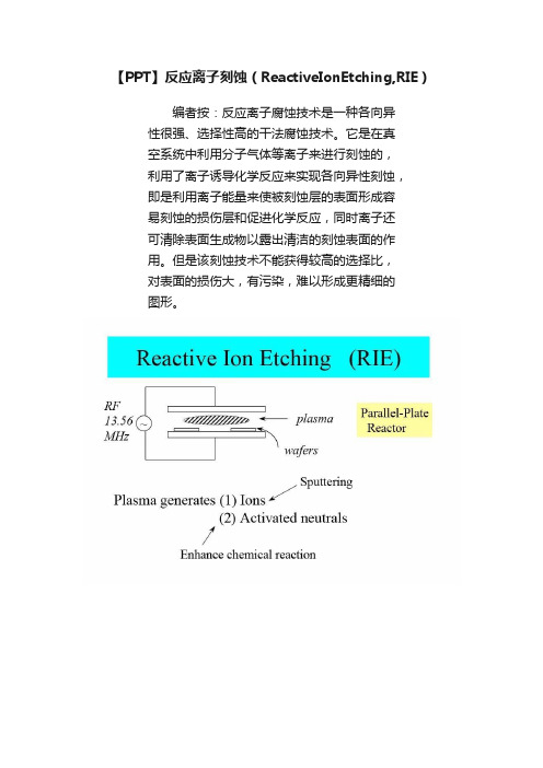
【PPT】反应离子刻蚀(ReactiveIonEtching,RIE)
编者按:反应离子腐蚀技术是一种各向异性很强、选择性高的干法腐蚀技术。
它是在真
空系统中利用分子气体等离子来进行刻蚀的,
利用了离子诱导化学反应来实现各向异性刻蚀,
即是利用离子能量来使被刻蚀层的表面形成容
易刻蚀的损伤层和促进化学反应,同时离子还
可清除表面生成物以露出清洁的刻蚀表面的作
用。
但是该刻蚀技术不能获得较高的选择比,
对表面的损伤大,有污染,难以形成更精细的
图形。
看完有什么感想?
请留言参与讨论!
转自: U.C. Berkeley如侵权请联系:*******************。
DRIE深反应离子刻蚀技术
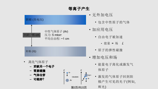
polymerization • 气体可以控制
• 尽管 CF4 只腐蚀 Si, 当更多的 Si 表面暴露时, 更多 的 F 被消耗掉,导致 F/C 减小,腐蚀减慢
• 加入 H2 消耗 F – 易导致 polymerization
•
加入
O2
消耗
第8页/共22页
干法刻蚀工艺的类型
• 断面特征取决于:
• 能量 • 压力 (平均自由程) • 偏压 • 方向性 • 晶向
第9页/共22页
干法刻蚀工艺的类型
腐蚀类型
能量
气体/蒸汽 腐蚀
无
- 各向同性, 化学, 选择性好
压力
高 (760-1 torr)
等离子腐蚀
10 ~ 100 Watts
中
- 各向同性, 化学, 有选择
第3页/共22页
辉光放电暗区
• 阴极暗区
• 大量能量气体离子移向阴极 • 在阴极产生的二次电子加速离开阴极 • 靠近阴极部分暗区中的净电贺数为正 • 产生大电场 (电压跌落很大) • 无辉光,原因是 e- 能量很高,主要离化气体原子很少激发电子
第4页/共22页
什么是 “干法” 刻蚀?
• 在湿法腐蚀液中, 腐蚀反应剂来自与液体中
(>100 torr)
反应离子腐蚀
100 Watts
低
- 方向性, 物理 & 化学, 有选择
(10-100 mtorr)
溅射腐蚀剂
100~1000 Watts 低
- 方向性, 物理, 低选择性
(~10 mtorr)
第10页/共22页
干法腐蚀: 气体混合 • Chlorofluorocarbons (CFCs)的消除
