MMST3906贴片三极管 SOT-323三极管封装MMST3906规格参数
BC807W贴片三极管 SOT-323三极管封装BC807W规格参数
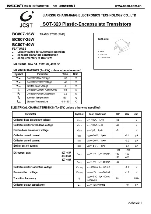
IC= -10mA, IB=0 IE= -1μA, IC=0
VCB= -20 V , IE=0 VCE= -20 V , IB=0 VEB= -5 V , IC=0
IC=-500mA, IB= -50 mA VCE= -1V, VCMHz IC= -500mA IC= -10mA
1. BASE 2. EMITTER 3. COLLECTOR
ELECTRICAL CHARACTERISTICS (Ta=25℃ unless otherwise specified)
Parameter Collector-base breakdown voltage Collector-emitter breakdown voltage Emitter-base breakdown voltage Collector cut-off current Collector cut-off current Emitter cut-off current DC current gain 807-16W 807-25W 807-40W Collector-emitter saturation voltage Base-emitter voltage hFE(2) VCE(sat) VBE(on) fT Cob VCE= -1V, IC= -500mA Symbol VCBO VCEO VEBO ICBO ICEO IEBO hFE(1) Test conditions IC= -10μA, IE=0 Min -50 -45 -5 -0.1 -0.2 -0.1 100 VCE= -1V, IC= -100mA 160 250 40 -0.7 -1.2 80 10 V V MHz pF 250 400 600 Max Unit V V V μA μA μA
MMST4403贴片三极管 SOT-323三极管封装MMST4403规格参数
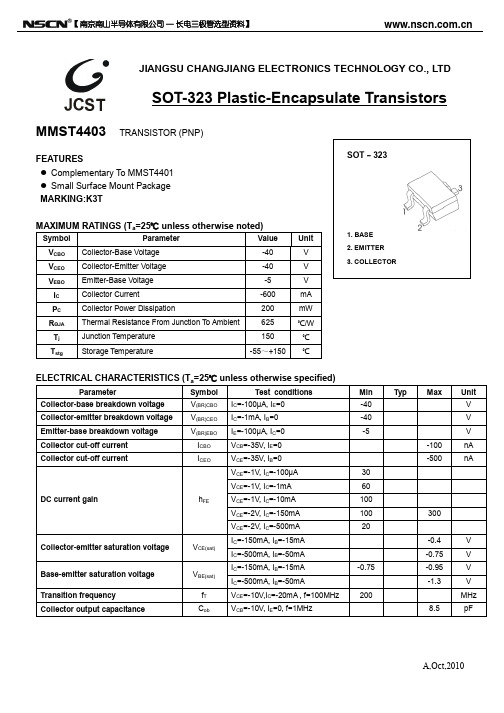
A,Oct,2010JIANGSU CHANGJIANG ELECTRONICS TECHNOLOGY CO., LTDSOT-323 Plastic-Encapsulate TransistorsMMST4403 TRANSISTOR (PNP)FEATURES● Complementary To MMST4401● Small Surface Mount PackageMARKING:K3TMAXIMUM RATINGS (T a =25℃ unless otherwise noted) SymbolParameter Value Unit V CBOCollector-Base Voltage -40 V V CEOCollector-Emitter Voltage -40 V V EBOEmitter-Base Voltage -5 V I CCollector Current -600 mA P CCollector Power Dissipation 200 mW R ΘJAThermal Resistance From Junction To Ambient 625 ℃/W T jJunction Temperature 150 ℃ T stg Storage Temperature -55~+150 ℃ ELECTRICAL CHARACTERISTICS (Ta =25℃ unless otherwise specified) ParameterSymbol Test conditions Min Typ MaxUnit Collector-base breakdown voltageV (BR)CBO I C =-100µA, I E =0 -40 V Collector-emitter breakdown voltageV (BR)CEO I C =-1mA, I B =0 -40 V Emitter-base breakdown voltageV (BR)EBO I E =-100µA, I C =0 -5 V Collector cut-off currentI CBO V CB =-35V, I E =0 -100 nA Collector cut-off current I CEO V CE =-35V, I B =0-500 nA V CE =-1V, I C =-100µA30 V CE =-1V, I C =-1mA60 V CE =-1V, I C =-10mA100 V CE =-2V, I C =-150mA100 300 DC current gain h FE V CE =-2V, I C =-500mA20 I C =-150mA, I B =-15mA -0.4 V Collector-emitter saturation voltageV CE(sat) I C =-500mA, I B =-50mA -0.75 V I C =-150mA, I B =-15mA -0.75 -0.95 V Base-emitter saturation voltageV BE(sat) I C =-500mA, I B =-50mA -1.3 V Transition frequencyf T V CE =-10V,I C =-20mA , f=100MHz 200 MHz Collector output capacitance C ob V CB =-10V, I E =0, f=1MHz 8.5 pF 【南京南山半导体有限公司 — 长电三极管选型资料】 【南京南山半导体有限公司 — 长电三极管选型资料】The bottom gasketThe top gasket3000×1 PCS 3000×15 PCS Label on the Reel Label on the Inner Box Label on the Outer Box QA Label Seal the boxwith the tape Seal the boxwith the tape Stamp “EMPTY”on the empty box Inner Box: 210mm ×208mm ×203m m Outer Box: 440mm ×440mm ×230mm。
2SA1611贴片三极管 SOT-323三极管封装2SA1611参数

Dimensions In Millimeters
Min.
Max.
0.900
1.100
0.000
0.100
0.900
1.000
0.200
0.400
0.080
0.150
2.000
2.200
1.150
1.3502.150 Nhomakorabea2.450
0.650 TYP.
1.200
1.400
0.525 REF.
0.260
0.460
0°
8°
The bottom gasket
3000×15 PCS
Label on the Reel 3000×1 PCS
Seal the box with the tape
The top gasket
Stamp “EMPTY” on the empty box
Seal the box with the tape
FEATURES High DC Current Gain High Voltage Complementary to 2SC4177
SOT–323
MAXIMUM RATINGS (Ta=25℃ unless otherwise noted)
Symbol
Parameter
Value
VCBO Collector-Base Voltage
Collector output capacitance
Cob
*Pulse test: pulse width ≤350μs, duty cycle≤ 2.0%.
CLASSIFICATION OF hFE
RANK
RANGE
PZTA42贴片三极管 SOT-323三极管封装PZTA42规格参数
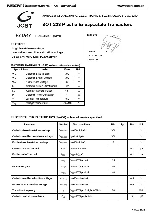
Symbol Para
meter
Value
Unit
VCBO
Collector-Base Voltage
300
V
VCEO
Collector-Emitter Voltage
300
V
VEBO
Emitter-Base Voltage
6
V
IC
Collector Current -Continuous
0.2
A
ICM
VCE(sat) IC=20mA,IB=2mA
VBE(sat) IC=20mA,IB=2mA
fT
VCE=20V,IC=10mA,f=100MHz
Cob
VCB=20V,IE=0,f=1MHz
Min Typ Max Unit
300
V
300
V
6
V
0.1
μA
0.1
μA
25
40
40
0.5
V
0.9
V
50
MHz
3
8
40000
2. 7 寸 包装流程图(Packing procedure):
2 包装规格(Packing spec):
封装 载带/盖带
卷盘
包装箱
PKG
tape
Reel
Box
只/盘 盘/盒
只/盒
pcs/reel reel/box pcs/box
7”盘 SOT-23 包
SOT-223 IC-ZD-04 (IC-JP-04) 装箱 *1 1000
pF
B,May,2012
【 南京南山半导体有限公司 — 长电三极管选型资料】
贴片R系列三极管参数
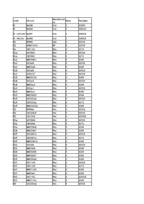
Nec Rho Rho Tfk Nec HP SGS Nec Nec Nec Nec HP Phi Sie Nec Nec Nec Nec Nec Nec Nec Nec Nec Nec Nec Nec Nec Nec Nec Nec Nec Nec Nec Nec Nec Nec Nec Nec Nec Nec Nec Nec Nec Nec Nec Nec Nec
Nec Nec Nec Nec Nec Nec Nec Nec Nec Nec Nec Nec Rho Sie Sie Rho Rho Rho Rho Mot Sie Sie Sie Sie Sie Sie Sie Sie Sie Sie Sie Sie Sie Sie Sie Nec Sie Sie Sie Sie Nec Rho Sie Sie Sie Sie Sie
RGs RHs RHs RHs RHs RHs RH RHs RIs RKs RKs RKM RK RR RR RVZ RW RZC RZC
BFS482 BFR183 BFR183W BFR183T BFP183 BFP183W 2SC3357 BFS483 BFP196 BFP194 BFR194 RK7002 2SC3357 BBY59-02V BFR93P MMST4126 BFR194 SST4124 MMST4124
N N N R WQ S R WQ N N N RQ N TQ WQ N N N N N N N WQ WQ WQ WQ WQ WQ N N N N N N N WQ WQ WQ WQ WQ WQ N N N N N N
SOT323 SOT23 SC59 SOT143 SOT143 SOT23R SOT143 SOT323 SOT323 SOT323 SOT145 SOT23 SOT143 SOT143 SOT23 SOT23 SOT323 SOT23 SOT323 SOT23 SOT323 SOT143 SOT343 SOT143 SOT343 SOT143 SOT343 SOT23 SOT23 SOT323 SOT23 SOT323 SOT23 SOT323 SOT143 SOT343 SOT143 SOT343 SOT143 SOT343 SOT23 SOT23 SOT323 SOT23 SOT323 SOT23
BC856W贴片三极管 SOT-323三极管封装BC856W规格参数

Collector cut-off current
DC current gain
BC856AW, 857AW,858AW BC856BW, 857BW,858BW
BC857CW,BC858CW
Collector-emitter saturation voltage
ICBO hFE VCE(sat)
VCB= -30 V , IE=0 VCE= -5V, IC= -2mA IC=-100mA, IB= -5mA
0.200
0.400
0.080
0.150
2.000
2.200
1.150
1.350
2.150
2.450
0.650 TYP.
1.200
1.400
0.525 REF.
0.260
0.460
0°
8°
Dimensions In Inches
Min.
Max.
0.035
0.043
0.000
0.004
0.035
0.039
Seal the box with the tape
The top gasket
Stamp “EMPTY” on the empty box
Seal the box with the tape
QA Label
Label on the Inner Box Inner Box: 210mm×208mm×203mm
T =100℃
a
T =25℃ a
-10 -0.1
180 150 120
90 60 30
0 0
-1
-10
COLLECTOR CURRENT I (mA) C
A3 (MBT3906DW 双通用目的晶体管 6脚贴片)

<1ns +0.5V
*Total shunt capacitance of test jig and connectors Figure 1. Delay and Rise Time Equivalent Test Circuit Figure . Storage and Fall Time Equivalent Test Circuit
TYPICAL TRANSIENT CHARACTERISTICS TJ=25 C
10 7.0 5000 3000 2000
TJ=125 C
CAPACITANCE (pF)
VCC=40V IC/IB=10
Q CHARGE (pC)
5.0
Cobo Cibo
1000 700 500 300 200 100
100
hoe OUTPUT ADMITTANCE (µ mhos)
0.1 0.2 0.3 0.5 0.7 1.0 2.0 3.0 5.0 7.0 1.0
70 50 30 20
hfe DC CURRENT GAIN
200
100 70 50
10 7 5 0.1 0.2 0.3 0.5 0.7 1.0 2.0 3.0 5.0 7.0 1.0
查询MBT3906DW供应商
MBT3906DW
Dual General Purpose Transistor PNP+PNP Silicon
* “G” Lead(Pb)-Free
4 5 6 3 2 1
6 5
4
1
2
3
SOT-363(SC-88)
Maximum Ratings
2SC4116贴片三极管 SOT-323三极管封装2SC4116规格参数

MAXIMUM RATINGS (Ta=25℃ unless otherwise noted)
Symbol VCBO VCEO VEBO IC PC TJ Tstg
Parameter Collector-Base Voltage Collector-Emitter Voltage Emitter-Base Voltage Collector Current -Continuous Collector Power Dissipation Junction Temperature Junction and Storage Temperature
0°
8°
The bottom gasket
3000×15 PCS
Label on the Reel 3000×1 PCS
Seal the box with the tape
The top gasket
Stamp “EMPTY” on the empty box
Seal the box with the tape
CLASSIFICATION OF hFE Rank Range
Marking
O 70-140
LO
Y
LG
BL 350-700
LL
B,Dec,2011
Typical Characteristics
2SC4116
COLLECTOR CURRENT I (mA) C
0°
8°
Dimensions In Inches
Min.
Max.
0.035
0.043
0.000
0.004
0.035
0.039
0.008
0.016
0.003
2SA1586贴片三极管 SOT-323三极管封装2SA1586参数

JIANGSU CHANGJIANG ELECTRONICS TECHNOLOGY CO., LTDSOT-323 Plastic-Encapsulate Transistors2SA1586 TRANSISTOR (PNP)FEATURES● High DC Current Gain● High Voltage and High Current.● Complementary to 2SC4116● Small PackageAPPLICATIONS● General Purpose Amplification.MAXIMUM RATINGS (T a =25℃ unless otherwise noted)SymbolParameter Value Unit V CBOCollector-Base Voltage -50 V V CEOCollector-Emitter Voltage -50 V V EBOEmitter-Base Voltage -5 V I CCollector Current -150 mA P CCollector Power Dissipation 100 mW R ΘJAThermal Resistance From Junction To Ambient 1250 ℃/W T jJunction Temperature 150 ℃ T stg Storage Temperature -55~+150 ℃ ELECTRICAL CHARACTERISTICS (T a =25℃ unless otherwise specified) ParameterSymbol Test conditions Min Typ Max Unit Collector-base breakdown voltageV (BR)CBO I C =-100µA, I E =0 -50V Collector-emitter breakdown voltageV (BR)CEO I C =-1mA, I B =0 -50V Emitter-base breakdown voltageV (BR)EBO I E =-100µA, I C =0 -5 V Collector cut-off currentI CBO V CB =-50V, I E =0 -100 nA Emitter cut-off currentI EBO V EB =-5V, I C =0 -100 nA DC current gainh FE V CE =-6V, I C =-2mA 70 400 Collector-emitter saturation voltageV CE(sat) I C =-100mA, I B =-10mA -0.3 V Transition frequencyf T V CE =-10V,I c =-1mA 80 MHz Collector output capacitance C ob V CB =-10V, I E =0, f=1MHz 7 pFCLASSIFICATION OF h FERANKO Y GR(G) RANGE70–140 120–240 200–400 MARKING SO SY SGB,Mar,2012 【南京南山半导体有限公司 — 长电三极管选型资料】-0.1-1-10-100-300-600-900-12000255075100125150020406080100120-10-100-1000101001000110-0-2-4-6-8-1010100-3BASE-EMMITER VOLTAGE V BE (mV)CO L L E C T O R C U R R E N T I C(m A ) -150I V —— B A S E -E M I T T E R S A T U R A T I O N V O L T A G E V B E s a t (m V )COLLECTOR CURREMT I C (mA) P C —— T a AMBIENT TEMPERATURE T a ()℃C O L L E C T O R P O W E R D I S S I P A T I O N P C (m W ) I V —— CO L L E C T O R -E M I T T E R S A T U R A T I O N VOLT AG EVCEsa t(mV )COLLECTOR CURREMT I C (mA)300-30-300302SA1586Typical Characteristics I h —— D C C U R R E N T G A I N h F E COLLECTOR CURRENT I C (mA) -0.33V /V C /C —— REVERSE VOLTAGE V (V)C A P A C I T A N C E C (pF )C O L L E C T O R C U R R E N T I C(m A )COLLECTOR-EMITTER VOLTAGE V CE (V)30COLLECTOR CURRENT I C (mA)T R A N S I T I O N F R E Q U E N C Y f T (M H z )500 I f —— B,Mar,2012 【南京南山半导体有限公司 — 长电三极管选型资料】The bottom gasketThe top gasket3000×1 PCS 3000×15 PCS Label on the Reel Label on the Inner Box Label on the Outer Box QA Label Seal the boxwith the tape Seal the boxwith the tape Stamp “EMPTY”on the empty box Inner Box: 210mm ×208mm ×203m m Outer Box: 440mm ×440mm ×230mm。
PZTA06贴片三极管 SOT-323三极管封装PZTA06规格参数
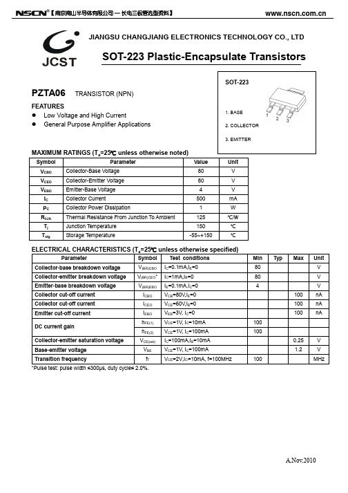
SOT-223
1. BASE 2. COLLECTOR
3. EMITTER
MAXIMUM RATINGS (Ta=25℃ unless otherwise noted)
【 南京南山半导体有限公司 — 长电三极管选型资料】
Symbol
A A1 A2 b c D D1 E E1 e e1 L θ
Dimensions In Millimeters
Min
Max
1.520
1.800
0.000
0.100
1.500
1.700
0.660
0.820
0.250
0.014
0.244
0.252
0.114
0.122
0.130
0.146
0.269
0.278
0.091(BSC)
0.177
0.185
0.035
0.045
0°
10°
SOT223 包装(SOT223 PACKING)
编带包装(Tape&Reel Packing):
1.包装流程图(Packing procedure):
【 南京南山半导体有限公司 — 长电三极管选型资料】
JIANGSU CHANGJIANG ELECTRONICS TECHNOLOGY CO., LTD
SOT-223 Plastic-Encapsulate Transistors
PZTA06 TRANSISTOR (NPN)
Parameter
PZTA92贴片三极管 SOT-323三极管封装PZTA92规格参数

-300
V
Emitter-base breakdown voltage
V(BR)EBO IE=-0.1mA,IC=0
-5
V
Collector cut-off current
ICBO
VCB=-200V,IE=0
-250 nA
Emitter cut-off current
IEBO
VEB=-3V, IC=0
FEATURES High Voltage Driver Applications
SOT-223
1. BASE 2. COLLECTOR
3. EMITTER
MAXIMUM RATINGS (Ta=25℃ unless otherwise noted)
Symbol
Parameter
VCBO
Collector-Base Voltage
-100 nA
hFE(1) VCE=-10V, IC=-1mA
25
DC current gain
hFE(2) VCE=-10V, IC=-10mA
40
hFE(3) VCE=-10V, IC=-30mA
25
Collector-emitter saturation voltage
VCE(sat) IC=-20mA,IB=-2mA
V
—— I
CEsat
C
T =100℃ a
-100
T =25℃ a
-10 -0.1
-1
-10
COLLECTOR CURRENT I (mA) C
I —— V
-100
C
BE
COMMON EMITTER
V = -10V CE
BC818 贴片三极管 SOT-323三极管封装BC818规格参数

JIANGSU CHANGJIANG ELECTRONICS TECHNOLOGY CO., LTDSOT-23 Plastic-Encapsulate TransistorsBC818-16 BC818-25 BC818-40 TRANSISTOR (NPN)FEATURES zFor general AF applications zHigh collector current zHigh current gain z Low collector-emitter saturation voltageELECTRICAL CHARACTERISTICS (T a =25℃ unless otherwise specified)ParameterSymbol Test conditions M in Typ M ax U nit Collector-base breakdown voltageV CBO I C = 10μA, I E =0 30 V Collector-emitter breakdown voltageV CEO I C = 10mA, I B =0 25 V Emitter-base breakdown voltageV EBO I E = 10μA, I C =0 5 V Collector cut-off currentI CBO V CB = 25 V ,I E =0 0.1 μA Emitter cut-off currentI EBO V EB = 4V, I C =0 0.1 μA h FE(1) V CE = 1V, I C = 100mA 100 630 DC current gainh FE(2) V CE = 1V, I C = 300mA 60 Collector-emitter saturation voltageV CE (sat) I C = 500mA, I B = 50mA 0.7 V Base-emitter saturation voltageV BE (sat) I C = 500mA, I B = 50mA 1.2 V Base-emitter voltageV BE V CE =1V, I C = 500mA 1.2 V Collecter capactianceC ob V CB =10V ,f=1MHz 6 pF Transition frequency f T V CE = 5 V, I C = 50mAf=100MHz 170 MHzCLASSIFICATION OF h FE (1)Rank BC818-16 BC818-25 BC818-40 Range 100-250 160-400 250-630 Marking 6E 6F 6GCOLLECTORA,May,2011【南京南山半导体有限公司 — 长电三极管选型资料】 【南京南山半导体有限公司 — 长电三极管选型资料】The bottom gasketThe top gasket3000×1 PCS 3000×15 PCS Label on the Reel Label on the Inner Box Label on the Outer Box QA Label Seal the boxwith the tape Seal the boxwith the tape Stamp “EMPTY”on the empty box Inner Box: 210mm ×208mm ×203m m Outer Box: 440mm ×440mm ×230mm。
MMBT3906 SOT-23 规格书推荐

2N3906 / MMBT3906 / PZT3906 — PNP General-Purpose Amplifier2N3906 / MMBT3906 / PZT3906PNP General-Purpose AmplifierOrdering InformationPart NumberMarkingPackagePacking MethodPack Quantity2N3906BU 2N3906TO-92 3L Bulk 100002N3906TA 2N3906TO-92 3L Ammo 20002N3906TAR 2N3906TO-92 3L Ammo 20002N3906TF2N3906TO-92 3L Tape and Reel 20002N3906TFR 2N3906TO-92 3L Tape and Reel 2000MMBT39062A SOT-23 3L Tape and Reel 3000PZT39063906SOT-223 4LTape and Reel25002N3906MMBT3906PZT3906E B CTO-92SOT-23SOT-223Mark:2ACBEE BCCDescriptionThis device is designed for general-purpose amplifier and switching applications at collector currents of 10 mA to 100 mA.2N3906 / MMBT3906 / PZT3906 — PNP General-Purpose AmplifierAbsolute Maximum Ratings (1)Stresses exceeding the absolute maximum ratings may damage the device. The device may not function or be opera-ble above the recommended operating conditions and stressing the parts to these levels is not recommended. In addi-tion, extended exposure to stresses above the recommended operating conditions may affect device reliability. The absolute maximum ratings are stress ratings only. Values are at T A = 25°C unless otherwise noted.Note:1.These ratings are based on a maximum junction temperature of 150°C.These are steady-state limits. ON Semiconductor should be consulted on applications involving pulsed or low-duty cycle operations.Thermal CharacteristicsValues are at T A = 25°C unless otherwise noted.Notes:2.Device is mounted on FR-4 PCB 1.6 inch X 1.6 inch X 0.06 inch.3.PCB size: FR-4, 76 mm x 114 mm x 1.57 mm (3.0 inch x4.5 inch x 0.062 inch) with minimum land pattern size.SymbolParameter ValueUnitV CEO Collector-Emitter Voltage -40V V CBO Collector-Base Voltage -40V V EBO Emitter-Base Voltage-5.0V I C Collector Current - Continuous-200mA T J, T STGOperating and Storage Junction Temperature Range-55 to +150°CSymbolParameterMaximumUnit2N3906(3)MMBT3906(2)PZT3906(3)P D Total Device Dissipation 6253501,000mW Derate Above 25°C5.0 2.88.0mW/°C R θJC Thermal Resistance, Junction to Case 83.3°C/W R θJAThermal Resistance, Junction to Ambient200357125°C/WNote:4.Pulse test: pulse width ≤ 300 μs, duty cycle ≤ 2.0%.C obo Output Capacitance f = 100 kHz4.5pF C ibo Input Capacitance V EB = -0.5 V, I C = 0, f = 100 kHz10.0pF NFNoise FigureI C = -100 μA, V CE = -5.0 V, R S = 1.0 k Ω,f = 10 Hz to 15.7 kHz 4.0dBSWITCHING CHARACTERISTICSt d Delay Time V CC = -3.0 V, V BE = -0.5 V I C = -10 mA, I B1 = -1.0 mA 35ns t r Rise Time 35ns t s Storage Time V CC = -3.0 V, I C = -10 mA, I B1 = I B2 = -1.0 mA225ns t fFall Time75nsON Semiconductor and are trademarks of Semiconductor Components Industries, LLC dba ON Semiconductor or its subsidiaries in the United States and/or other countries.ON Semiconductor owns the rights to a number of patents, trademarks, copyrights, trade secrets, and other intellectual property. A listing of ON Semiconductor’s product/patent coverage may be accessed atON Semiconductor makes no warranty, representation or guarantee regarding the suitability of its products for any particular purpose, nor does ON Semiconductor assume any liability arising out of the application or use of any product or circuit, and specifically disclaims any and all liability, including without limitation special, consequential or incidental damages.PUBLICATION ORDERING INFORMATION。
PZT3906贴片三极管 SOT-223三极管封装PZT3906参数
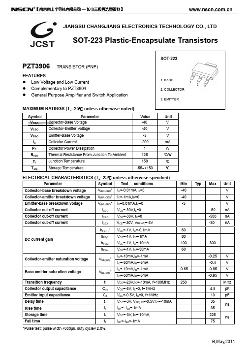
Collector-base breakdown voltage Collector-emitter breakdown voltage Emitter-base breakdown voltage Collector cut-off current Collector cut-off current Collector cut-off current
SOT-223
FEATURES Low Voltage and Low Current Complementary to PZT3904 General Purpose Amplifier and Switch Application
1. BASE 2. COLLECTOR 3. EMITTER
3.300
3.700
6.830
7.070
2.300(BSC)
4.500
4.700
0.900
1.150
0°
10°
Dimensions In Inches
Min
Max
0.060
0.071
0.000
0.004
0.059
0.067
0.026
0.032
0.010
0.014
0.244
0.252
0.114
0.122
60 80 100 60
-0.65
250
300
-0.25 -0.4 -0.85 -0.95
4.5 10 35 35 225 75
V V V V MHz pF pF
ns
ns
*Pulse test: pulse width ≤300μs, duty cycle≤ 2.0%.
BC857W贴片三极管 SOT-323三极管封装BC857W规格参数

JIANGSU CHANGJIANG ELECTRONICS TECHNOLOGY CO.,LTD
SOT-323 Plastic-Encapsulate Transistors
BC856AW, BW TRANSISTOR BC857AW, BW,CW BC858AW, BW,CW
1. BASE 2. EMITTER 3. COLLECTOR
DEVICE MARKING
BC856AW=3A; BC856BW=3B; BC857AW=3E; BC857BW=3F;BC857CW=3G; BC858AW=3J; BC858BW=3K; BC858CW=3L
A,May,2011
【 南京南山半导体有限公司 — 长电三极管选型资料】
(PNP) SOT-323
FEATURES Ideally suited for automatic insertion For Switching and AF Amplifier Applications MAXIMUM RATINGS (Ta=25℃ unless otherwise noted)
Hale Waihona Puke The bottom gasket
Label on the Reel 3000×15 PCS 3000×1 PCS
The top gasket Stamp “EMPTY” on the empty box Seal the box with the tape
Seal the box with the tape
Transition frequency
MHz
Collector capacitance
MCCSEMI DMMT3906 三极管说明书

V(BR)EBO IBL ICEX
hFE(1) hFE(2) hFE(3) hFE(4) hFE(5)
-5
60 80 100 60 30
Collector-Emitter Saturation Voltage
VCE(sat)
Base-Emitter Saturation Voltage
Compliant. See Ordering Information)
DMMT3906
PNP Plastic Encapsulate
Transistors
Maximum Ratings @ 25°C Unless Otherwise Specified
• Operating Junction Temperature Range: -65℃ to +150℃ • Storage Temperature Range: -65℃ to +150℃ • Typical Thermal Resistance: 625℃/W Junction to Ambient
Common Emitter
-500μA
TA=25°C
-450μA
-400μA
-350μA -300μA
-250μA
-200μA -150μA
-100μA
IB=-50μA
-4
-8
-12
-16
-20
Collector-Emitter Voltage (V)
Fig. 3 - Collector-Emitter Saturation Voltage Characteristics
L
NOTE TYP.
0.65
BC857W贴片三极管SOT-323三极管封装BC857W规格参数

BC857W贴片三极管SOT-323三极管封装BC857W规格参数JIANGSU CHANGJIANG ELECTRONICS TECHNOLOGY CO.,LTDSOT-323 Plastic-Encapsulate TransistorsBC856AW, BW TRANSISTOR (PNP) BC857AW, BW ,CW BC858AW, BW ,CW FEATURES y Ideally suited for automatic insertion y For Switching and AF Amplifier Applications MAXIMUM RATINGS (T a =25℃ unless otherwise noted) Symbol Parameter Value UnitV CBO Collector-Base VoltageBC856WBC857W BC858W-80 -50 -30 VV CEO Collector-Emitter VoltageBC856WBC857WBC858W-65 -45 -30 V V EBOEmitter-Base Voltage -5 V I CCollector Current –Continuous -0.1A P C*Collector Power Dissipation 150mW T JJunction Temperature 150 ℃ T stg Storage Temperature -65-150℃DEVICE MARKINGBC856AW=3A; BC856BW=3B;BC857AW=3E; BC857BW=3F;BC857CW=3G;BC858AW=3J; BC858BW=3K; BC858CW=3LA,May,2011ELECTRICAL CHARACTERISTICS (T a =25℃ unless otherwise specified) ParameterSymbol Test conditions Min MaxUnit Collector-base breakdown voltage BC856W BC857W BC858W V CBO I C = -10μA, I E =0 -80 -50 -30 V Collector-emitter breakdown voltage BC856W BC857W BC858W V CEO I C = -10mA, I B =0 -65 -45 -30 V Emitter-base breakdown voltage V EBO I E = -1μA, I C =0 -5 V Collector cut-off currentI CBO V CB = -30 V , I E =0 -15 nA DC current gain BC856AW,857AW,858AW BC856BW, 857BW,858BW BC857CW,BC858CW h FE V CE = -5V, I C = -2mA 125 220 420 250 475 800 Collector-emitter saturation voltageV CE(sat) I C =-100mA, I B = -5mA -0.65V Base-emitter saturation voltage V BE(sat) I C = -100mA, I B = -5mA -1.1 V Transition frequency f T V CE = -5V, I C = -10mAf=100MHz100 MHz Collector capacitance C ob V CB =-10V, f=1MHz 4.5 pFA,May,2011 【南京南山半导体有限公司—长电三极管选型资料】The bottom gasketThe top gasket3000×1 PCS 3000×15 PCS Label on the Reel Label on the Inner Box Label on the Outer Box QA Label Seal the box with the tape Seal the boxwith the tape Stamp “EMPTY”on the empty box Inner Box: 210mm ×208mm ×203m m Outer Box: 440mm ×440mm ×230mm。
ROHM UMT3906 SST3906 MMST3906 说明书

TransistorsRev.B 1/4PNP General Purpose TransistorUMT3906 / SST3906 / MMST3906z Features1) BV CEO > −40V (I C = −1mA)2) Complements the T3904/SST3904/MMST3909. 3) Low capacitance.z Package, marking, and packaging specificationsz Absolute maximum ratings (T a=25°C)z Electrical characteristics (T a=25°C)ParameterSymbol BV CBO BV CEO BV EBO Min.Max.Typ.−40−40−5−50−50−0.25−0.85−0.95−0.4−−−−0.65Unit ConditionsCollector-base breakdown voltage Collector-emitter breakdown voltage Emitter-base breakdown voltage Emitter cutoff currentI CES I EBO −−−−−−−−−−−−−−−−−−−−−−−−−−−−−−−−−−−−−Collector cutoff current Emitter input capacitance Delay time Rise time Storage tiem Fall timeCollector-emitter saturation voltage Base-emitter saturation voltageV CE(sat)V BE(sat)−DC current transfer ratio Transition frequency Collector output capacitance h FE Cob Cib f T 606030250 4.51035352257580100300td tr tstg tfV V V V VnA nA MHz pF pF ns ns ns nsI C = −10µA I C = −1mA I E = −10µA V CB = −30V V EB = −3VV CE = −1V, I C = −0.1mA V CE = −1V, I C = −1mAV CE = −1V, I C = −10mA V CE = −1V, I C = −50mA V CE = −1V, I C = −100mAV CE = −20V, I E =10mA, f=100MHz V CB = −10V, f=100kHz, I E =0A V CB = −0.5V, f=100kHz, I C =0AV CC = −3V, V BE(OFF)= −0.5V,I C = −10mA, I B1= −1mA V CC = −3V, V BE(OFF)= −0.5V,I C = −10mA, I B1= −1mA V CC = −3V, I C = −10mA, I B1= −I B2= −1mA V CC = −3V, I C = −10mA, I B1= −I B2= −1mAI C /I B = −10mA/ −1mA I C /I B = −10mA/ −1mA I C /I B = −50mA/ −5mA I C /I B = −50mA/ −5mAType UMT3906UMT3R2A T1063000SST3906SST3R2A T1163000MMST3906SMT3R2A T1463000Packaging type Marking Code Basic ordering unit (pieces)Parameter Symbol V CBO V CEO V EBO PdTj Tstg Limits −40−40−56.20.35SST3906,MMST3906SST3906,MMST3906UMT3906150−55 to +150Unit V V V °C°CCollector-base voltageCollector-emitter voltage Emitter-base voltageI O −0.2Collector current Collector Power dissipation Junction temperature Storage temperature A ∗W W ∗ When mounted on a 7 5 0.6mm ceramic board.++TransistorsRev.B 2/4z Electrical characteristics curvesI C -C O L L E C T O R C U R R E N T (m A )V CE -COLLECTOR-EMITTER VOLTAGE (V)Fig.1 Grounded emitter output characteristicsV C E (s a t )C O L L E C T O R E M I T T E R S A T U R A T I O N V O L T A G E (V )I C EMITTER COLLECTOR CURRENT (mA)Fig.2 Collector-emitter saturationvoltage vs. collector currenth F E -D C C U R R E N T G A I NI C -COLLECTOR CURRENT (mA)Fig.3 DC current gain vs.collector current ( Ι )h F E -D C C U R R E N T G A I NI C -COLLECTOR CURRENT (mA)Fig.4 DC current gain vs. collector current ( ΙΙ )TransistorsRev.B 3/4h F E -A C C U R R E N T G A I NI C -COLLECTOR CURRENT (mA)Fig.5 AC current gain vs. collector currentV B E (S A T )B A S E E M I T T E R S A T U R A T I O N V O L T A G E (V )I C -COLLECTOR CURRENT (mA)Fig.6 Base-emitter saturation voltage vs. collector currentV B E (O N )-B A S E E M I T T E R O N V O L T A G E (V )I C-COLLECTOR CURRENT (mA)Fig.7 Grounded emitter propagationcharacteristics t o n -TU R N O N T I M E (n s )I C -COLLECTOR CURRENT (mA)Fig.8 Turn-on time vs. collectorcurrent t r -R I S E T I M E (n s )I C -COLLECTOR CURRENT (mA)Fig.9 Rise time vs. collectorcurrentt S -S T O R A G ET I M E (n s )I C -COLLECTOR CURRENT (mA)Fig.10 Storage time vs. collectorcurrent t f -F A L LT I M E (n s )I C -COLLECTOR CURRENT (mA)Fig.11 Fall time vs. collectorcurrent C A P A C I T A N C E (p F )REVERSE BIAS VOLTAGE (V)Fig.12 Input / output capacitance vs. voltageTransistorsRev.B 4/4V C E C O L L E C T O R -E M I T T E R V O L T A G E (V )I C -COLLECTOR CURRENT (mA)Fig.13 Gain bandwidth productf T -C O R R E N T G A I N -B A N D W I D T H P R O D U C T (M H z )I C -COLLECTOR CURRENT (mA)Fig.14 Gain bandwidth productvs. collector currenth -P A R A M E T E RN O R M A L I Z E D T O 1m AI C -COLLECTOR CURRENT (mA)Fig.15 h parameter vs. collector currentN F -N O I S E F I G U R E (d B )f-FREQUENCY (Hz)Fig.16 Noise vs. collector current101I C B O -C O L L E C T O R C U T O F F C U R R E N T (A )T A -AMBIENT TEMPERATURE (°C)Fig.17 Noise characteristics ( Ι )R S -S O U R C E R E S I S T A N C E (Ω)I C -COLLECTOR CURRENT (mA)Fig.18 Noise characteristics ( ΙΙ )R S -S O U R C E R E S I S T A N C E (Ω)I C -COLLECTOR CURRENT (mA)Fig.19 Noise characteristics (ΙΙΙ)R S -S O U R C E R E S I S T A N C E (Ω)I C -COLLECTOR CURRENT (mA)Fig.20 Noise characteristics ( )ΙΛAppendix1-Rev2.0Thank you for your accessing to ROHM product informations.More detail product informations and catalogs are available, please contact your nearest sales office.ROHM Customer Support SystemTHE AMERICAS / EUPOPE / ASIA / JAPANContact us : webmaster@rohm.co.jpAppendix。
MMST3906

Output Capacitance Delay time Rise time Storage time Fall time
f=1MHz
VCC=-3V, IC=-10mA VBE(off) =-0.5V,IB1=-1mA VCC=-3V, IC=-10mA IB1= IB2= -1mA
A2
A
Dimensions In Inches Max 0.043 0.004 0.039 0.016 0.006 0.087 0.053 0.096 0.026TYP 0.047 0.021REF 0.010 0° 0.018 8° 0.055 0.035 0.000 0.035 0.008 0.003 0.079 0.045 0.085
TRANSISTOR
( PNP )
SOT-323
1.BASE 2.EMITTER 3.COLLECTOR
1.25±0.05
2.30±0.05
1.30±0.03
1.01 REF 0.30
Unit:mm
otherwise
conditions IE=0
specified)
MIN -40 -40 -5 -0.1 -0.1 -0.1 100 300 MAX UNIT V V V
JIANGSU CHANGJIANG ELECTRONICS TECHNOLOGY CO., LTD
SOT-323 Plastic-Encapsulate Transistors
MMST3906
FEATURES Power dissipation PCM : 0.2 W(Tamb=25℃) Collector current ICM : -0.2 A Collector-base voltage V(BR) CBO: -40 V Operating and storage junction temperature range T J ,T stg: -55℃ to +150℃ ELECTRICAL CHARACTERISTICS(Tamb=25℃ unless
- 1、下载文档前请自行甄别文档内容的完整性,平台不提供额外的编辑、内容补充、找答案等附加服务。
- 2、"仅部分预览"的文档,不可在线预览部分如存在完整性等问题,可反馈申请退款(可完整预览的文档不适用该条件!)。
- 3、如文档侵犯您的权益,请联系客服反馈,我们会尽快为您处理(人工客服工作时间:9:00-18:30)。
A,Oct,2010
JIANGSU CHANGJIANG ELECTRONICS TECHNOLOGY CO., LTD
SOT-323 Plastic-Encapsulate Transistors
MMST3906 TRANSISTOR (PNP)
FEATURES
Complementary to MMST3904
MARKING:K5N
MAXIMUM RATINGS (T a =25℃ unless otherwise noted) Symbol
Parameter Value Unit V CBO
Collector-Base Voltage -40 V V CEO
Collector-Emitter Voltage -40 V V EBO
Emitter-Base Voltage -5 V I C
Collector Current -200 mA P C
Collector Power Dissipation 200 mW R ΘJA
Thermal Resistance From Junction To Ambient 625 ℃/W T j
Junction Temperature 150 ℃ T stg Storage Temperature -55~+150 ℃ ELECTRICAL CHARACTERISTICS (T a
=25℃ unless otherwise specified) Parameter
Symbol Test conditions Min Typ Max
Unit Collector-base breakdown voltage
V (BR)CBO * I C =-10µA, I E =0 -40 V Collector-emitter breakdown voltage
V (BR)CEO * I C =-1mA, I B =0 -40 V Emitter-base breakdown voltage
V (BR)EBO * I E =-10µA, I C =0 -5 V Base cut-off current
I BL * V CE =-30V, V EB(Off)=-3V -50 nA Collector cut-off current
I CEX * V CE =-30V, V EB(Off)=-3V -50 nA V CE =-1V, I C =-100µA 60 V CE =-1V, I C =-1mA
80 DC current gain h FE * V CE =-1V, I C =-10mA
100 300 I C =-10mA, I B =-1mA -0.2 V Collector-emitter saturation voltage
V CE(sat)* I C =-50mA, I B =-5mA -0.3 V I C =-10mA, I B =-1mA -0.65 -0.85 V Base-emitter saturation voltage
V BE(sat)* I C =-50mA, I B =-5mA -0.95 V Transition frequency
f T V CE =-20V,I C =-10mA , f=100MHz 250 MHz Collector output capacitance
C ob V CB =-5V, I E =0, f=1MHz 4.5 pF Collector output capacitance
C ib V EB =-0.5V, I E =0, f=1MHz 10 pF Delay time
t d 35 ns Rise time
t r V CC =-3V, V BE(off)=-0.5V, I C =-10mA, I B1=-1mA 35 ns Storage time
t s
225 ns Fall time t f V CC =3V, I C =-10mA, I B1= I B2=-1mA 75 ns
*Pulse test: pulse width ≤300μs, duty cycle≤ 2.0%.
【南京南山半导体有限公司 — 长电三极管选型资料】
【南京南山半导体有限公司 — 长电三极管选型资料】
The bottom gasket
The top gasket
3000×1 PCS 3000×15 PCS Label on the Reel Label on the Inner Box Label on the Outer Box QA Label Seal the box
with the tape Seal the box
with the tape Stamp “EMPTY”
on the empty box Inner Box: 210mm ×208mm ×203m m Outer Box: 440mm ×440mm ×230mm。
