西门子GRAPH-action说明
西门子培训课程:graph练习及实验

详细描述
利用图算法构建一个推荐系统,根据用户的历史行为和 偏好,为用户推荐相关联的物品或服务。可以使用图中 的关联规则挖掘、协同过滤等技术来实现个性化推荐, 并通过实验验证推荐系统的准确性和效果。
Graph进阶学习
05
使用第三方库进行Graph操作
功能强大
使用第三方库进行Graph操作可以提供丰富的功能和工具,例如使用NetworkX 库进行图的创建、编辑和可视化,以及使用D3.js库将图形数据动态呈现于网页上 。这些库提供了大量的方法和函数,使得对图形的操作更加灵活和高效。
查找节点和边
总结词
在构建复杂的网络或系统时,查找特定的节 点和边是必不可少的操作。
详细描述
在西门子Graph编程中,查找特定的节点和 边是常见的操作。这可以通过使用Graph类 提供的方法来实现。通过查找特定的节点和 边,可以更好地理解网络或系统的结构和行 为,并进行相应的优化和控制。在实际应用 中,需要根据具体需求进行查找操作,以实 现系统性能和行为的优化和控制。
西门子培训课程graph 练习及实验
目录
• Graph基础概念 • Graph编程实践 • Graph算法应用 • Graph实验项目 • Graph进阶学习
Graph基础概念
01
什么是Graph
总结词
图论中的基本概念
详细描述
Graph是一个由节点(顶点)和边组成的数据结构,用于表示对象之间的关系。 节点通常表示对象,而边则表示对象之间的关系。
Graph在大数据处理中的应用
可视化呈现
图结构数据非常适合可视化呈现,可以通过图形的方式直观地展示数据之间的关系和模式。在大数据处理中,可视化可以帮 助更好地理解数据和分析结果。
西门子顺序功能图语言S7 Graph的应用

5.6 顺序功能图语言S7 Graph 的应用5.6.1 S7 Graph 语言概述S7 Graph 语言是S7-300/400的顺序功能图语言,遵从IEC 61131-3标准的规定。
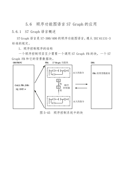
1.顺序控制程序的结构一个顺序控制项目至少需要一个调用S7 Graph FB 的块,一个S7 Graph FB 和它的背景数据块。
CALL FB1, DB1SQ_INIT :=OB/FB/FCFB1DB1永久性指令永久性指令S7 Graph 功能块FB1的背景数据块图5-45 顺序控制系统中的块图5-46 S7 Graph 编辑器步与转换跳步分支中止选择序列的分支选择序列的合并并行序列的分支并行序列的合并选择对象预选/直接插入监视时间T 插入监视时间U 插入永久条件插入动作插入永久性FB ,FC 调用插入顺序控制器“Drag and Drop ”模式时与鼠标一起移动的图形图5-49 顺序控制器工具条与移动的图形3.S7 Graph 的显示模式在View 菜单中选择显示顺序控制器(Sequencer )、单步和永久性指令。
(1)在顺序控制器显示方式,执行菜单命令“View>Display with ”,可以选择:Symbols :显示符号表中的符号地址; Comments :显示块和步的注释;Conditions and Actions:显示转换条件和动作;Symbol List:在输入地址时显示下拉式符号地址表。
(2)单步显示模式只显示一个步和转换的组合,还可以显示Supervision:监控被显示的步的条件;Interlock:对被显示的步互锁的条件;执行命令“View>Display with> comments”显示和编辑步的注释。
用“↑”键或“↓”键可以显示上一个或下一个步与转换的组合。
(3)在“permanent instructions”(永久性指令)显示方式,可以对顺序控制器之前或之后的永久性指令编程。
graph7说明书 (1)

S1 N
M1.4
S0 N
M2.4
V1 N
M2.5
V0 N
M2.6
动作在事件发生的扫描周期 中执行一次
时间
• A1 = 确认 • L1 = 联锁错误到达 • L0 = 联锁错误离开 • S1 = 步已激活 • S0 = 步已取消激活 • V1 = 监控错误到达 • V0 = 监控错误离开
SIMATIC S7
总是与事件关联。
在发生事件的扫描循环中 引发执行一次动作
也可以与联锁条件C组合
计数器
• CS = 设置计数 • CU =增计数 • CD =减计数 • CR = 复位计数
定时器
• TL = 扩展脉冲 • TD = 延时开 • TR = 复位时间
SIMATIC S7
Siemens AG 2001。保留所有权利。
最小参数集
SIMATIC S7
Siemens AG 2001。保留所有权利。
日期:2020/3/9 文件:PRO2_12E.19
标准参数集
SITRAIN
自动化与驱动培训教材
激活调试功能
步骤
• 下载顺控器FB和背景数据块
- 使用菜单项PLC -> Download,把顺控序列FB和背景数据块下载到PLC
日期:2020/3/9 文件:PRO2_12E.9
顺控器 2 S7
T6 T9
S8
T7 S9
T9
S8
跳转到 步8
SITRAIN
自动化与驱动培训教材
"Door_closed" 联锁
()
"Time_off"
监控
()
动作编程
"输入1" "输 2" 步激活条件
西门子S7-GRAPH培训教程

Date:15.09.2004File:GRAPH_01e.1SIMATIC S7Siemens AG 2000. All rights reserved.IntroductionDate:15.09.2004File:GRAPH_01e.3SIMATIC S7Siemens AG 2000. All rights reserved.S7-GRAPHDesignProgrammingStart-upDocumentationArchivingHMIS7-GRAPH:Tool for Graphics Supportfor SequencersIEC 1131-3-CompliantDate:15.09.2004File:GRAPH_01e.4SIMATIC S7Siemens AG 2000. All rights reserved.Diagram of a fill level controllerCorrectionInlet valveMPump 1Outlet valveMPump 2OverflowFullEmptyPROCESSCONTROLHardware User programl Query input signals l Generate limit values lControl pumps etc.lMessages:Fill level...Inputs OutputsExample of fill level controllerPrinciple of a Logic Control System ProgramDate:15.09.2004File:GRAPH_01e.5SIMATIC S7Siemens AG 2000. All rights reserved.Example of an assembly lineProximity switchesLight barriersMotorLEDsAcknowledge switchesPrinciple of a Sequential Control System ProgramDate:15.09.2004File:GRAPH_01e.6SIMATIC S7Siemens AG 2000. All rights reserved.ProcessStep-by-step execution ofthe processNo YesControl program:Programmed as logic control system(with STEP 7)Examples:-Fill level controller -Lift controllerControl program:Programmed as logic control system (with S7-GRAPH)Examples:-Assembly line -Car wash-Traffic light control -Production processes -Machine processes -Process engineeringDecision Support for Sequential Control System (Sequencer)Date:15.09.2004File:GRAPH_01e.7SIMATIC S7Siemens AG 2000. All rights reserved.What applications are sequential control systems suitable for ?Sequential processes :Tasks controlled by signals or timersTime-critical processes that are susceptible t o faults §Methodical procedure improves transparency §Program is easier to understand §Maintenance,servicing,diagnostics Advantage: Fast error removalApplication examples§Car wash §Assembly line§Assembly conveyor §Machine tools §Transfer line §Presses§Process engineering §Packaging technology§Process control and monitoringDifferentiation from Other ToolsDate:15.09.2004File:GRAPH_01e.8SIMATIC S7Siemens AG 2000. All rights reserved.* * *Step :Graphic representation with directed links " * * * " =Step name* * *Initial step:Graphic representation with directed links " * * * " = Initial step name* * *"a""b""c""d""a":Identifier character (operation e.g. S )"b": Action name (e.g. MOTOR 1)"c": Boolean "display" variable"d": Action in: ( e.g.declaration + STL code)Actions are controlled according to specific rules that are described in detail in the IEC1131-3standard.In general,they are:1. Action block for activation2.Enable /interlock of individual actions3.Step switchingAction block with actionsStructural Elements of a Sequencer : StepsBasic elements of a sequencer to comply with IEC 1131-3Date:15.09.2004File:GRAPH_01e.9SIMATIC S7Siemens AG 2000. All rights reserved.* * ** * ** * ** * *i2.4i2.3Extract from IEC 1131-3:TransitionsA transition represents the condition whereby control passes from one or more steps preceding the transition to one or more successor steps along the corresponding directed link. The transition shall be represented by a horizontal line across the vertical directed link.The direction of evolution following the directed links shall be from the bottom of the predecessor step(s) to the top of the successor step(s).Each transition shall have an associated transition condition which is the result of the evaluation of a single Boolean expression.XStructural Elements of a Sequencer : TransitionBasic elements of a sequencer to comply with IEC 1131-3Date:15.09.2004File:GRAPH_01e.10SIMATIC S7Siemens AG 2000. All rights reserved.Basis: SIMATIC Manager with STEP 7 in LAD, FBD, STLManualToolLAD, FBDincl. ex.incl. ex.S7-GRAPH Software Package (Multilingual)Date:15.09.2004File:GRAPH_01e.11SIMATIC S7Siemens AG 2000. All rights reserved.Simple,user-friendly description ofsequential processesProgramming sequencersto DIN EN 6 1131 (correspondsto IEC 1131-3)Can be used forS7-300 (CPU314and higher )and S7-400Simple configuration (full graphics ,windows technology ,zoom functionality )Processing speed independent of the sequencer lengthEasy interfacing with process visualization and diagnostics--> "ProAgent for OP" (OP25...OP37)--> "ProAgent for WinCC " (OP47, FI25orPCs/PGs)--> "ProDiag" (Transline 2000)Process synchronization can be activated in S7-GRAPHCharacteristics of S7-GRAPHDate:15.09.2004File:GRAPH_02e.1SIMATIC S7Siemens AG 2000. All rights reserved.Project Planning and ConfigurationDate:15.09.2004File:GRAPH_02e.2SIMATIC S7Siemens AG 2000. All rights reserved.Planning and ConfigurationDate:15.09.2004File:GRAPH_02e.3SIMATIC S7Siemens AG 2000. All rights reserved.Step: Step No. (No.max. 999) and step name(max. 24contiguous characters )Initial step:Execution start without queryinga start transition after sequencer RESET (INIT_SQ) or return jump or initial start of the sequencerTransition The transition contains the conditions which allow mode -dependent enabling from one stepto the successor step .S3Step 3S1Step 1T5trans5Basic Elements of a Sequencer (1)Date:15.09.2004File:GRAPH_02e.4SIMATIC S7Siemens AG 2000. All rights reserved.S xxx End of sequencer Switches off the sequencer completely whenend of sequencer is reached .The sequencer can only be started again by selective enabling of a step inthis sequencer (e.g. initial step or via step selection)Application:tasks that are executed once, e.g.approach /retract programJump to a step (forwards or backwards)Application:cyclic execution,machine loopBasic Elements of a Sequencer (2)Date:15.09.2004File:GRAPH_02e.5SIMATIC S7Siemens AG 2000. All rights Date:15.09.2004File:GRAPH_02e.6SIMATIC S7Siemens AG 2000. All rights reserved.Open simultaneous branch Synchronization of all associated steps after the openingbranch in the same PLC cycle.Then each branch is independently executed .Possible toenable all branches in the same PLC cycleFirst steps are also called opening stepsClose simultaneous branch Synchronization at joining, i.e. all branches wait for oneanother until all steps preceding the closing branch are active .Only then is execution switched simultaneouslyto the leftbranch via the successor transition .Last steps are also called closing steps .Basic Elements of a Sequencer (4)Date:15.09.2004File:GRAPH_02e.7SIMATIC S7Siemens AG 2000. All rights reserved.Basic Elements of a Sequencer (5)Date:15.09.2004File:GRAPH_02e.8SIMATIC S7Siemens AG 2000. All rights reserved.Display always as S7-GRAPH sequencer Save Save As...Open/Insert GRAPH source Source filesSave Save As...Open/InsertS7block Blocks S1G e n e r a t eS o u r c e C o m p i l e (C o m p i l e r )Test run possible!No test run possible!Sequencer as FBS13T1T13Sequencer as GRAPH source file S1S13T1T13S1Symbols Entry/use in STEP 7symbol listEntry/use in STEP 7symbol list Storing a SequencerDate:15.09.2004File:GRAPH_02e.9SIMATIC S7Siemens AG 2000. All rights reserved.Creating, Opening and Saving a Sequencer as GRAPH Source FileDate:15.09.2004File:GRAPH_02e.10SIMATIC S7Siemens AG 2000. All rights reserved.How to Use the S7 -GRAPH Source EditorDate:15.09.2004File:GRAPH_02e.11SIMATIC S7Siemens AG 2000. All rights reserved.Important: Before opening theFB you must have selected"GRAPH"as the language it was created in! (cannot be edited later)Important: Before opening theFB you must have selected"GRAPH"as the language it was created in! (cannot be edited later )Creating, Opening and Saving a Sequencer as FB (+DB)Date:15.09.2004File:GRAPH_03e.1SIMATIC S7Siemens AG 2000. All rights reserved.Programming Steps and TransitionsDate:20.09.2004File:GRAPH_03e.3SIMATIC S7Siemens AG 2000. All rights reserved.Application Settings and Block SettingsDate:20.09.2004File:GRAPH_03e.4SIMATIC S7Siemens AG 2000. All rights reserved.Application Settings, General Tab (1)Date:20.09.2004File:GRAPH_03e.5SIMATIC S7Siemens AG 2000. All rights reserved.Application Settings, General Tab (2)Date:20.09.2004File:GRAPH_03e.6SIMATIC S7Siemens AG 2000. All rights reserved.Application Settings, Editor (1)Date:20.09.2004File:GRAPH_03e.7SIMATIC S7Siemens AG 2000. All rights reserved.Application Settings, Editor (2)Date:20.09.2004File:GRAPH_03e.8SIMATIC S7Siemens AG 2000. All rights reserved.View Types: OverviewDate:20.09.2004File:GRAPH_03e.9SIMATIC S7Siemens AG 2000. All rights reserved.View Types: Single PageDate:20.09.2004File:GRAPH_03e.10SIMATIC S7Siemens AG 2000. All rights reserved.View Types: Single StepDate:20.09.2004File:GRAPH_03e.11SIMATIC S7Siemens AG 2000. All rights reserved.Interlock condition missing!Supervision error occurred!Interlock = 0 (error):Supervision= 1 (error):Enable if transition satisfied No enable if transition satisfied FB parameter ERR_FLT = 1FB parameter ERR_FLT = 1Error display in statusError display in status "C" actions are not carried out Actions are carried out"NC" actions are reset•FB parameter ERR_FLT = 0FB parameter ERR_FLT = 0•Error no longer present Error no longer present •"C" actions are executed Satisfied transition enabled (with acknowledge if required)C= 0 -->Interlock V= 1 -->Supervision + STOPC = 1 -->InterlockV = 0 -->Supervision+ continue+ continue+ continueInterlocks and SupervisionsDate:20.09.2004File:GRAPH_03e.12SIMATIC S7Siemens AG 2000. All rights reserved.View Types: Permanent InstructionsS1S2T1T2S4T3Initial stepTransitionS5S6T4T5Seq. endAlternative branch, open Simultaneous branch, openAlternative branch, closeSimultaneous branch, close Seq.1S7S8T6T7S9T9Seq.2S8T9Jump tostep 8Elements of a Sequencer, OverviewInsert Step + Transition Insert JumpOpen Alternative Branch Close Alternative Branch Open Simultaneous Branch Close Simultaneous BranchInsert Sequencer End Insert SequencerInsert Permanent Condition Insert Permanent FB/FC Call Insert actionDrag & Drop DirectDate:20.09.2004File:GRAPH_03e.15SIMATIC S7Siemens AG 2000. All rights reserved.Editing Sequencers (2)Date:20.09.2004File:GRAPH_03e.16SIMATIC S7Siemens AG 2000. All rights reserved.Actions (1) , Editing Action BlocksDate:20.09.2004File:GRAPH_03e.17SIMATIC S7Siemens AG 2000. All rights reserved.Action block with simple instructionsN = Non-stored S = Set (Stored) D =Time Delayed, delayed by time T, non -storedL = Time Limited, non -stored, time -delayed CALL = Block call (only if step is active)Action block_2N M1.1S M1.2R M1.3D M1.4T#1H2M3SL M1.5T#4MSCALL FC1Actions (2) , Standard ActionsDate:20.09.2004File:GRAPH_03e.18SIMATIC S7Siemens AG 2000. All rights reserved.Action block with conditional instructionsConditionsAn action indicated with"C" (Condition)is only executed if the interlockcondition of the step is satisifed ("C" = 1).An interlock error occurs if the condition is zero. The action with the C condition is not executed. The step is highlighted and the error message "Error"is generated.Action block _3NC M1.1SC M1.2RC M1.3DC M1.4T#1H2M3SLC M1.5T#4MSCALLC FB5,DB3Actions (3) , Interlock -Dependent ActionsIns t r u c t io n A d d r e s s E x p la n a t io nN C A 1.0A s lo n g a s t h e s te p is a c tiv e a n d th e c o n d itio n f u lf ille d , s ig n a l A 1.0 = 1, o th e r w is e 0S C A 1.0A s lo n g a s t h e s te p is a c tiv e a n d th e c o n d itio n f u lf ille d , A 1.0 =1 a n d th e n r e m a in s 1.R C A 1.0A s lo n g a s t h e s te p is a c tiv e a n d th e c o n d itio n f u lf ille d , A 1.0 = 0 a n d th e n r e m a in s 0.D CA 1.0T #<c o n s t>A t e x p ir y o f th e tim e s p e c if ie d in <c o n s t > a n d a s lo n g a s th e s te p is a c tiv e a n d th e c o n d itio n f u lf ille d , s ig n a l A 1.0 =1. If th e s te p is n o t a c tiv e ,s ig n a l = 0.L C A 1.0T #<c o n s t>A s lo n g a s t h e s te p is a c tiv e a n d th e c o n d itio n f u lf ille d , f o r t h e s p e c if ie d t im e <c o n s t> s ig n a l A 1.0 = 1. If t h e s te p is n o t a c tiv e , s ig n a l = 0.C A L L C FB 5,D B 3C a lls th e s p e c if ie d b lo c k if th e c o n d itio n isf u lf ille d. A f te r b lo c k e x e c u tio n , e x e c u tio n o f th e G R A P H c o n tin u e s.Date:20.09.2004File:GRAPH_03e.19SIMATIC S7Siemens AG 2000. All rights reserved.1. Double-click on error message;error is highlighted in screen.Compiler is activated with:1. Store FB2. Consistency checkpile GRAPH sourceTroubleshooting procedure:2. Correct in programCompiler MessagesDate:20.09.2004File:GRAPH_04e.1SIMATIC S7Siemens AG 2000. All rights reserved.Debug and Start -UpDate:20.09.2004File:GRAPH_04e.3SIMATIC S7Siemens AG 2000. All rights pile / Save Tab (1)Date:20.09.2004File:GRAPH_04e.4SIMATIC S7Siemens AG 2000. All rights pile / Save Tab (2)Date:20.09.2004File:GRAPH_04e.5SIMATIC S7Siemens AG 2000. All rights pile / Save Tab (3)Date:20.09.2004File:GRAPH_04e.6SIMATIC S7Siemens AG 2000. All rights pile / Save Tab (4)Date:20.09.2004File:GRAPH_04e.7SIMATIC S7Siemens AG 2000. All rights reserved. Minimum call parameters-1 input parameter for sequencer controlStandard call parameters-12 input parameters for sequencer control-7 output parameters for displaying operatingstates-Input/output parameters do not need tobeset (default values)Date:20.09.2004File:GRAPH_04e.8SIMATIC S7Siemens AG 2000. All rights reserved.•Maximum call parameters-17 input parameters for sequencercontrol-12 output parameters for displayingoperating states-Parameters do not need to be set(default values)Types of FB Call (2)Date:20.09.2004File:GRAPH_04e.9SIMATIC S7Siemens AG 2000. All rights reserved. Maximum V5 (user-defined)-29 input parameters forsequencer control-32 output parameters fordisplaying operating states-Parameters need notbe set-Parameters that are notrequired can be deselected-Additional parameters can be custom-definedTypes of FB Call (3)Date:20.09.2004File:GRAPH_04e.10SIMATIC S7Siemens AG 2000. All rights reserved.Input parameter set:Output parameter set:User-Defined Parameter Set (V5.0 and higher)Date:20.09.2004File:GRAPH_04e.11SIMATIC S7Siemens AG 2000. All rights reserved.Static variablesTemporary variablesUser-Defined Static and Temporary Variables (V5.0 and higher)Date:20.09.2004File:GRAPH_04e.12SIMATIC S7Siemens AG 2000. All rights reserved.The test function visualizes evolution and disturbances of the sequencer. Overview§Active and disturbed steps §Valid and satisfied transitions §Skipped steps and transitions Single Page§Overview display §Program status of transitions §Status of actions §Undisturbed and total activation time of stepsStatus in Overview and Single Page Display。
「编程」西门子强大的GRAPH语言你会用吗?

「编程」西门子强大的GRAPH语言你会用吗?熟悉西门子的人都知道,西门子的PLC支持的语言很多,除了最基本的LAD,FBD,STL之外,还有很多在国内不是很常见的语言,其中包括GRAPH,SCL,CFC,SFC等等。
这些语言虽然不是很常见,可以对于一些特定的场合却可以起到很重要的作用。
今天我们讲一讲GRAPH的用法。
西门子系列PLC包括300、400、1500系列(除S7-1200外)均支持GRAPH指令,而S7-200系列虽然没有GRAPH语言,但是却拥有GRAPH的缩减版,那就是步进命令,有过实际编程经验的朋友都知道,在一些特定的场合需要使用循环反复的步进指令,这个指令可以自己编写,也可以直接使用PLC内部的步进指令。
只是GRAPH语言比步进语言强大得多了,所以西门子自300PLC 开始,专门做了一个插件(升级包),该插件的授权需要在STEP7软件的基础上额外购买。
博途软件因为系统软件的高度集成化,所以GRAPH也集成在了博途软件里,所以安装过博途软件的朋友可以直接在博途里使用该语言编写300/400/1500系列PLC的程序,下面用一个简单的例子来说明GRAPH指令的应用。
假设,我们需要做一个顺序控制的程序,程序分为4步,每步对应不同的生产工艺即不同的输出,每步以不同的脉冲命令作为使能条件。
步骤如下:1)电脑需要安装带仿真的博途软件。
2)打开软件,建立新项目3)添加一个新设备,这里选择cpu317-2dp,保存项目;4)回到程序编辑区,点开“程序块” 双击创建一个FB,选择GRAPH语言,依次编写程序,图示:5)在程序里输入指令如图;第一步,输出命令置位Q0.0第二步,执行条件为I0.2,输出命令为置位Q0.1第三步,执行条件为I0.3,输出命令为复位Q0.0和Q0.1第四步,执行条件为I0.4,输出命令为结束该程序块6)编写完程序后,回到OB1中调用FB1,系统会要求生成一个背景数据块,我采用默认数据块DB1,调用完程序后,我们填写FB1管角,仅需要填写第一个和第二个;第一个是中止功能块FB1命令,第二个是执行FB1功能块,也就是程序里第一步的执行条件。
S7-GRAPH编程

西门子顺序功能图语言S7Graph的应用
5.6 顺序功能图语言S7 Graph 的应用5.6.1 S7 Graph 语言概述S7 Graph 语言是S7-300/400的顺序功能图语言,遵从IEC 61131-3标准的规定。
1.顺序控制程序的结构一个顺序控制项目至少需要一个调用S7 Graph FB 的块,一个S7 Graph FB 和它的背景数据块。
CALL FB1, DB1SQ_INIT :=OB/FB/FCFB1DB1永久性指令永久性指令S7 Graph 功能块FB1的背景数据块图5-45 顺序控制系统中的块图5-46 S7 Graph 编辑器步与转换跳步分支中止选择序列的分支选择序列的合并并行序列的分支并行序列的合并选择对象预选/直接插入监视时间T 插入监视时间U 插入永久条件插入动作插入永久性FB ,FC 调用插入顺序控制器“Drag and Drop ”模式时与鼠标一起移动的图形图5-49 顺序控制器工具条与移动的图形3.S7 Graph 的显示模式在View 菜单中选择显示顺序控制器(Sequencer )、单步和永久性指令。
(1)在顺序控制器显示方式,执行菜单命令“View>Display with ”,可以选择:Symbols :显示符号表中的符号地址; Comments :显示块和步的注释;Conditions and Actions:显示转换条件和动作;Symbol List:在输入地址时显示下拉式符号地址表。
(2)单步显示模式只显示一个步和转换的组合,还可以显示Supervision:监控被显示的步的条件;Interlock:对被显示的步互锁的条件;执行命令“View>Display with> comments”显示和编辑步的注释。
用“↑”键或“↓”键可以显示上一个或下一个步与转换的组合。
(3)在“permanent instructions”(永久性指令)显示方式,可以对顺序控制器之前或之后的永久性指令编程。
01、西门子S7-300PLC GRAPH顺控指令讲解和编程举例

182
精品PPT
互锁条件对程序运行的影响
简介 安装与使用 软件兼容性 应用举例 建立程序
编程界面
程序结构
编辑程序
应用(yìngyòng) 设定 调试程序
程序(chéngxù)演示
超过了90度
192
精品PPT
程序的手动/自动运行调试
简介 安装与使用 软件兼容性 应用举例 建立程序
启动搅拌电机,5分钟后关闭搅拌电机,
如果附加工艺选择为“0” :
则打开阀门D,流程结束。
如果附加工艺选择为“1”:
则打开阀门C,当液体 C到达限位C 时,关闭阀门C,
启动搅拌电机,10分钟后关闭搅拌电机,
打开阀门D,流程结束。
52
精品PPT
阀门D
工艺流程图
简介 安装与使用
软件兼容性
应用举例
建立程序
简介 安装与使用
软件兼容性 应用举例 建立程序
编程界面 程序结构
编辑程序 应用(yìngyòng)设 定 调试程序 程序(chéngxù)演 示
172
当前步骤
精品PPT
当前步骤时间
监控程序
简介 安装与使用
软件兼容性
应用举例 建立程序
编程界面 程序结构 编辑程序
应用(yìngyòng) 设定 调试程序
212
精品PPT
Tphroagnrkaymomu ing language S7-GRAPH
精品PPT
简介
安装与使用
软件兼容性
应用举例
建立程序
编程界面
程序结构
编辑程序
应用(yìngyòng)设 定
调试程序
西门子S7-300顺控GRAPH语言简要介绍

顺序控制顺序控制•顺序控制,就是按照生产工艺预先预定的程序,在各个输入信号的作用下,根据内部状态和时间的顺序,在生产过程中各个执行机构自动有序地进行操作。
•顺序控制设计法最基本的思路是将系统的一个工作周期划分为若干个顺序相连的阶段,这些阶段称为步,当系统处于某一步所在的阶段,称该步为活动步,步活动时所做的操作称为步的动作。
转换将相邻步之间隔开,使系统由当前步进入下一步的信号称为转换条件。
顺序控制•顺序控制设计方法最基本的思路是将系统的一个工作周期划分为若干个顺序相连的阶段,这些阶段称为步。
与系统的初始状态对应的步称为初始步,每个顺序功能图至少应该有一个初始步。
当系统处于某一步所在的状态,该步为“活动步”。
•使系统由当前步进入下一步的信号称为转换条件。
置复位指令的顺序控制程序•一、画出顺序控制功能图,为每个步分别分配对应的存储器位(M )。
•二、在顺控功能运行前设计初始化操作。
将初始步对应的存储器位置1,将其他步对应的存储器位置0。
一、当FC1运行时,每个扫描周期将M1.0取反。
二、当FC1未调用时,将T2置0。
三、FC1被调用时,进行初始化操作。
•Tips:上图初始化方法主要适用于块嵌套深度较大的情况。
初始化操作的方式还有OB100,或者利用调用块的上升沿等方式,要根据具体情况使用。
置复位指令的顺序控制程序•三、编写步与步之间的转换条件。
•四、编写对应步的输出动作。
GRAPH•目前还有很多PLC (例如S7-200和S7-1200)未配备顺序功能图语言,适合利用置复位指令的顺控编程方法。
•S7 GRAPH 语言是S7-300/400用于顺序控制编程的顺序功能图语言。
•GRAPH 编程界面初始步转换条件步对应动作跳转视图工具栏步与转换工具栏GRAPH•Options-Block settings •新建GRAPH功能块。
•在功能块内将VIEW下拉菜单选择LAD梯形图。
只保留初始化接口。
•Tips:Minimum:FB只包括INIT_SQ启动参数,如果程序仅仅会运行在自动模式,并且不需要其他的控制及监控功能,可以选择此模式。
ROS2学习之旅(8)——理解ROS2Graph中的动作(Action)

ROS2学习之旅(8)——理解ROS2Graph中的动作(Action)动作是ROS2中的⼀种通信类型,⽤于长时间运⾏的任务,它由三个部分组成:⽬标、反馈和结果。
动作建⽴在话题和服务之上,它的功能类似于服务,但动作是抢占式的(可以在执⾏时取消它们)。
它还提供稳定的反馈,⽽不是只返回⼀个响应的服务。
动作使⽤客户机-服务器模型,类似于发布者-订阅者模型。
“动作客户端”节点向“动作服务器”节点发送⼀个⽬标,该节点确认⽬标并返回⼀个反馈流和⼀个结果。
1.准备运⾏/turtlesim和/teleop_turtle两个节点,分别在两个终端运⾏:ros2 run turtlesim turtlesim_noderos2 run turtlesim turtle_teleop_key此时,出现窗⼝:2.使⽤动作当启动teleop_turtle节点时,在终端中输出:Use arrow keys to move the turtle.Use G|B|V|C|D|E|R|T keys to rotate to absolute orientations. 'F' to cancel a rotation.'Q' to quit.第⼆⾏对应⼀个动作。
注意:字母键G|B|V|C|D|E|R|T在键盘上的F键周围形成⼀个“⽅框”,F周围的每个键的位置都对应于turtlesim中海龟⽅向。
例如,E会将海龟的⽅向旋转到左上⾓。
请注意运⾏/turtlesim节点的终端,每当按下其中⼀个键时,就向/turtlesim节点的的动作服务器发送了⼀个⽬标,⽬标是将海龟旋转到⼀个特定的⽅向。
⼀旦海龟完成旋转,就会显⽰传递⽬标结果的消息:[INFO] [turtlesim]: Rotation goal completed successfullyF键将在执⾏过程中取消⽬标,演⽰了动作的可抢占特性。
试着按C键,然后在海龟完成旋转之前按F键。
Siemens 控制器说明书
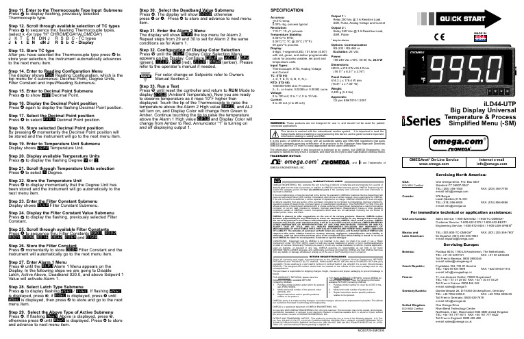
Step 30. Select the Deadband Value Submenu Press d . The display will show 020.0, otherwisepress b or c.Press d to store and advance to next menu item.Step 31. Enter the Alarm 2 MenuThe display will show ALR2the top menu for Alarm 2.Repeat steps from 29 and 30 to set for Alarm 2 the same conditions as for Alarm 1.Step 32. Configuration of Display Color Selection Press a until the COLR Display Color Selection Menu appears on the Display. Configure COLR as N.CLR /GRN (green), 1.CLR / RED (red), 2.CLR /AMBR (amber). Please refer to the operator’s manual if needed.For color change on Setpoints refer to Owners Manual Section 2.Step 33. Run a TestPress a until reset the controller and return to RUN Mode to display 075.0(Ambient Temperature). Now you are ready to observe temperature as it rises 10°F higher thandisplayed. Touch the tip of the Thermocouple to raise the temperature above the Alarm 2 High value 082.0, and AL2will turn on, and Display Color will change from Green to Amber. Continue touching the tip to raise the temperature above the Alarm 1 High value 087.0and Display Color will change from Amber to Red. Annunciator “1” is turning on and off displaying output 1.Step 11. Enter to the Thermocouple Type Input Submenu Press d to display flashing, previously selected Thermocouple type.Step 12. Scroll through available selection of TC types Press b to sequence thru flashing Thermocouple types,(select k -for type "K" CHROMEGA ®/ALOMEGA ®)J K T E N DIN J R S B C - TC types J k t E N dN J R S b C - DisplayStep 13. Store TC typeAfter you have selected the Thermocouple type press d to store your selection, the instrument automatically advances to the next menu item.Step 14. Enter to Reading Configuration MenuThe display shows RDG Reading Configuration, which is the top menu for 4 submenus: Decimal Point, Degree Units,Filter Constant and Input/Reading Submenus.Step 15. Enter to Decimal Point Submenu Press d to show DEC Decimal Point.Step 16. Display the Decimal Point positionPress d again to display the flashing Decimal Point position.Step 17. Select the Decimal Point position Press b to select FFF.F Decimal Point position.Step 18. Store selected Decimal Point positionBy pressing d momentarily the Decimal Point position will be stored and the instrument will go to the next menu item.Step 19. Enter to Temperature Unit Submenu Display shows TEMP Temperature Unit.Step 20. Display available Temperature Units Press d to display the flashing Degree °F or °C .Step 21. Scroll through Temperature Units selection Press b to select °F Degree.Step 22. Store the Temperature UnitPress d to display momentarily that the Degree Unit has been stored and the instrument will go automatically to the next menu item.Step 23. Enter the Filter Constant Submenu Display shows FLTR Filter Constant Submenu.Step 24. Display the Filter Constant Value Submenu Press d to display the flashing, previously selected Filter Constant.Step 25. Scroll through available Filter Constants Press b to sequence thru Filter Constants 0001, 0002,0004, 0008, 0016, 0032, 0064and 0128.Step 26. Store the Filter ConstantPress d momentarily to store 0004Filter Constant and the instrument will automatically go to the next menu item.Step 27. Enter Alarm 1 MenuPress a until the ALR1Alarm 1 Menu appears on the Display. In the following steps we are going to DisableLatch, Active Above, Deadband 020.0, and above Setpoint 1Value will activate Alarm 1.Step 28. Select Latch Type SubmenuPress d to display flashing DSBL / ENBL .If flashing DSBL is displayed, press a , if ENBL is displayed, press b until DSBL is displayed, then press d to store and go to the next menu item.Step 29. Select the Above Type of Active Submenu Press d . If flashing ABoV Above is displayed, press a ,otherwise press b until ABoV is displayed. Press d to store and advance to next menu item.MQS3720-SM/0305WARNING:These products are not designed for use in, and should not be used for, patient-connected applications.It is the policy of OMEGA to comply with all worldwide safety and EMC/EMI regulations that apply.OMEGA is constantly pursuing certification of its products to the European New Approach Directives.OMEGA will add the CE mark to every appropriate device upon certification.The information contained in this document is believed to be correct, but OMEGA Engineering,Inc.accepts no liability for any errors it contains, and reserves the right to alter specifications without notice.TRADEMARK NOTICE:®,®,, andare Trademarks ofOMEGA ENGINEERING, INC.®SPECIFICATIONAccuracy:+0.5°C temp;0.03% rdg. process typical Resolution:1°/0.1°; 10 µV process Temperature Stability:0.04°C/°C RTD;0.05°C/°C TC @ 25°C (77°F); 50 ppm/°C process Display:4-digit, 7-segment LED, 101.6mm (4.00”)with red, green, and amber programmable colors for process variable, set point and temperature units.Input Types:Thermocouple, RTD, Analog Voltage and Current TC: (ITS 90)J, K, T, E, R, S, B, C, N, L RTD: (ITS 68)100/500/1000 ohm Pt sensor2-, 3-, or 4-wire; 0.00385 or 0.00392 curve Voltage:0 to 100 mV, 0 to 1 V, 0 to 10 Vdc Current:0 to 20 mA (4 to 20 mA)Output 1†:Relay 250 Vac @ 3 A Resistive Load,SSR, Pulse, Analog Voltage and Current Output 2†:Relay 250 Vac @ 3 A Resistive Load,SSR, Pulse†Only for AlarmsOptions:Communication RS-232 / RS-485 or Excitation:24 VdcPower:100-240 Vac ±10%,50-60 Hz, 22.5 W Dimensions:480.0L x 210.8W x 95.4D mm (18.11" x 8.31" x 3.76")Panel Cutout:414.3 L x 179.4 W mm (16.31” L x 7.06” W)Weight:2,495 g (5.5 lbs)Approvals:CE per EN61010-1:2001This Quick Start Reference provides information onsetting up your instrument for basic operation. Thelatest complete Communication and OperationalManual as well as free Software and ActiveXControls are available at or onthe CD-ROM enclosed with your shipment.The instrument is a panel mount device protected in accordance with EN 61010-1:2001, electrical safety requirements for electrical equipment for measurement, control and laboratory.Remember that the unit has no power-on switch. Building installation should include a switch or circuit-breaker that must be compliant to IEC 947-1 and 947-3. SAFETY:•Do not exceed voltage rating on the label located onthe back of the instrument housing.•Always disconnect power before changing signal andpower connections.•Do not use this instrument on a work bench withoutits case for safety reasons.•Do not operate this instrument in flammable orexplosive atmospheres.EMC:•Whenever EMC is an issue, always use shielded cables.•Never run signal and power wires in the same conduit.•Use signal wire connections with twisted-pair cables.•Install Ferrite Bead(s) on signal wire close to theinstrument if EMC problems persist.。
WinCC -Step 7-Graph 的使用步骤:
WinCC 的使用步骤:1、创建项目:(WinCC资源管理器)1.1创建单用户项目:新建,选择Single-User Project ,OK输入项目名字(test)和新建文件夹名字,选择放置路径。
1.2指定系统组态:右击Tag Management , 选择 Add New Driver….. ,选择 SIMATIC S7 Protocol Suite.chn ,OK双击 SIMATIC S7 Protocol Suite 协议组,右击 PROFIBUS ,选择System Parameter,选择Unit 选项卡,修改采集卡型号:CP5611 (PROFIBUS) 确定。
1.3创建与自动化系统的链接:右击PROFIBUS,选择 New Driver Connection……,修改新的链接名字(test1),单击Properties ,修改链接地址(1),必须与自动化系统控制器的地址一致,这样WinCC才能根据地址找到相应的控制器。
也可以创建好以后再修改。
1.4创建变量:右击新建的链接,选择New Group……. 或New Tag….. 创建变量组或变量。
类型可以是DB 、Bit Memory 、Input 、Output。
修改变量名(Start),并且选择变量地址(M0.0)。
修改变量名(Stop),并且选择变量地址(M0.1)。
修改变量名(Light),并且选择变量地址(Q125.0)。
2、可视化系统:(图形编辑器)2.1创建画面:右击Graphics Designer ,选择 New Picture 。
修改文件名字分别为 Picture 1 , Picture 2 。
2.2添加静态文本或图形:双击Picture 2进入图形编辑器,添加三个按钮。
文本分别为开始,停止,返回。
再添加一个小灯。
双击Picture 1进入图形编辑器,添加两个按钮。
文本分别为进入,退出。
2.3使用变量链接画面元素:在Picture 1 中,双击进入按钮,打开按钮属性窗口。
西门子GRAPH-action说明

动作中的定时器 所有动作中的定时器都是事件相关的,另外事件决定着指令激活
的时间。也可以与互锁相设置。定时器指令仅在互锁条件满足的时候
一.动作种类 动作由以下几类组成: 1 标准动作 -带或不带互锁 2 事件相关的动作 - 带或不带互锁 - 激活或取消激活步 3 计数器,定时器和数值运算
二.空动作(步不带动作)
空动作就是步中不包含动作。空动作表现为一个动作步。后继条
件可靠。
三.标准动作(带或不带自锁)
所有标准动作都可以带自锁。动作仅在互锁满足的时候执行(带字
SFB/FB = 系统功能块/功能块;SFC/FC = 系统功能/功能 调用 FB/SFB,需要背景 DB 块
事件相关的动作-进入或离开步
其他步进入或离开使用 ON 与 OFF 指令。这些指令总是依靠步的 事件,另外事件决定步进入或离开的时间。
这些指令可以包含互锁。动作仅在互锁满足的时候执行。
事 指令 地 址 符 地 解释
件令
号
址位
S1, CS[ S0,L1,C] L0,V1, A1,R1
S1, CU[ S0,L1,C] L0,V1, A1,R1
S1, CD[ S0,L1,C] L0,V1, A1,R1
S1, CR[ S0,L1,C] L0,V1, A1,R1
C
<初始值> C
C
C
置位:当事件 发生时(与互锁满足 时候),计数器初 始值将被设置
SFB/FB = 系统功能块/功能块;SFC/FC = 系统功能/功能 调用 FB/SFB,需要背景 DB 块
S7_Graph_参数使用说明_清晰版

S7 Graph功能块的参数设置1.顺序控制系统的运行模式通过对S7 Graph FB的参数设置,可以选择顺序控制系统的4种运行模式(见“图2-1”),从而决定顺序控制器对步与步之间的转换的处理方式。
(1)自动(Automatic)模式在自动模式,当转换条件满足时,由当前步转换到下一步。
(2)手动(Manual)模式与自动模式相反,在手动模式时,转换条件满足并不能转换到后续步,步的活动或不活动状态的控制是用手动完成的。
(3)单步(Inching)模式单步模式与自动模式的区别在于它对步与步之间的转换有附加的条件,即只能在转换条件满足和输入参数T_PUSH的上升沿,才能转换到下一步。
(4)自动或切换到下一步(Automatic or step-by-step)模式在该模式,只要转换条件满足或在功能块的输入信号T_PUSH(见“表5-2”)的上升沿,都能转换到下一步。
在RUN模式下可以用功能块的输入参数来选择4种工作模式,在下列参数的上升沿激活相应的工作模式:SW_AUTO:自动模式;SW_MAN:手动模式;SW_TAP:单步(Inching)模式;SW_TOP:自动或切换到下一步(Automatic or Switch to next)模式。
2.S7 Graph FB的参数集S7 Graph FB有4种不同的参数集(见“表5-1”),“图5-1”是梯形图中最小参数集的S7 Graph FB符号,V5版的“Definable/Maximum”(可定义/最大)参数集使用“表5-2”和“表5-3”中所有的参数。
FB的参数集见“表5-1”,S7 Graph FB的输入参数见“表5-2”,S7 Graph FB的输出参数见“表5-3”,工作模式与S7 Graph FB的输入参数子关系见“表5-4”,4种工作模式都要使用的S7 Graph FB的输出参数见“表5-5”。
表5-1 FB的参数集在S7 Graph程序编辑器中执行菜单命令“Options” “Block Settings”,在出现的对话框的“Compile/Save”选项卡(见“图4-1”)的“FB Parameters”区中,可以选择需要的参数集。
01、西门子S7-300PLCGRAPH顺控指令讲解与编程举例
21/22
pTrhoagnrkamyomuing language S7-GRAPH
增加特性:
▪
多个顺控器(最多8个)
▪
步骤(每个顺控器最多250个)
▪
每个步骤的动作(每步最多100个)
▪
转换条件(每个顺控器最多250个)
▪
分支条件(每个顺控器最多250个)
▪
逻辑互锁(最多32个条件)
▪
监控条件(最多32个条件)
▪
事件触发功能
▪
切换运行模式:手动、自动及点动模式
2/22
安装与使用
11/22
编辑条件及动作
简介 安装与使用 软件兼容性 应用举例 建立程序 编程界面 程序结构 编辑程序 应用设定 调试程序 程序演示
12/22
设置互锁条件:箱体 温度低于设定值 只有在互锁条件满足且当前 步有效时,打开阀门A
步骤3 开始的条件 : 液位大于限定值
编辑条件及动作
简介 安装与使用 软件兼容性 应用举例 建立程序 编程界面 程序结构 编辑程序 应用设定 调试程序 程序演示
原
原
原
料
料
料
A
B
C
液位 C
液位 B
液位 A
阀门D
简单工艺描述: 初始化 打开阀门A,当液体 A 到达限位A 时,关闭阀门A, 打开阀门B,当液体 B到达限位B 时,关闭阀门B, 启动搅拌电机,5分钟后关闭搅拌电机,
如果附加工艺选择为“0” : 则打开阀门D,流程结束。
如果附加工艺选择为“1”: 则打开阀门C,当液体 C到达限位C 时,关闭阀门C, 启动搅拌电机,10分钟后关闭搅拌电机, 打开阀门D,流程结束。
本例选择最 小参数
西门子GRAPH-action说明
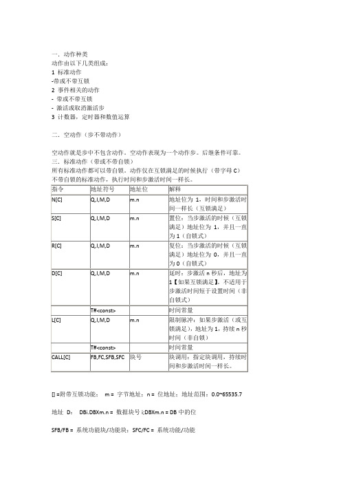
一.动作种类动作由以下几类组成:1 标准动作-带或不带互锁2 事件相关的动作- 带或不带互锁- 激活或取消激活步3 计数器,定时器和数值运算二.空动作(步不带动作)空动作就是步中不包含动作。
空动作表现为一个动作步。
后继条件可靠。
三.标准动作(带或不带自锁)所有标准动作都可以带自锁。
动作仅在互锁满足的时候执行(带字母C)不带自锁的标准动作,执行时间和步激活时间一样长。
[] =附带互锁功能;m = 字节地址;n = 位地址;地址范围:0.0~65535.7地址D:DBi.DBXm.n = 数据块号i;DBXm.n = DB中的位SFB/FB = 系统功能块/功能块;SFC/FC = 系统功能/功能调用FB/SFB,需要背景DB块四.事件相关的动作动作可以包含事件。
在步中,事件的状态是可以改变的,监控条件或者互锁条件或者信息确认或者注册设置。
如果动作包含事件,事件信号状态将具有边沿检测。
意味着,指令将在事件发生的时候执行。
时间和信号赋值步:1 S1:步将激活2 S0:步将取消激活。
监控条件:1 V1:监控条件发生错误(扰乱)2 V2:监控条件错误清除(没有扰乱)互锁条件1 L0:互锁条件进入状态2 L1:互锁条件离开状态(例如扰乱)3 C:互锁条件满足消息和注册1 A1:消息确认2 R1:注册设置(REG_EF/REG_S 上升沿输出)五时间相关的动作-带或不带互锁所有标准动作除了带D或L指令,都可以与事件结合[] =附带互锁功能;m = 字节地址;n = 位地址;地址范围:0.0~65535.7地址D:DBi.DBXm.n = 数据块号i;DBXm.n = DB中的位SFB/FB = 系统功能块/功能块;SFC/FC = 系统功能/功能调用FB/SFB,需要背景DB块事件相关的动作-进入或离开步其他步进入或离开使用ON与OFF指令。
这些指令总是依靠步的事件,另外事件决定步进入或离开的时间。
这些指令可以包含互锁。
PLC_编程语言_graph
S7-GRAPH编程Programming with S7-GRAPHGetting Started Edition (2008年7月)摘要本文档主要用于讨论与S7-GRAPH编程相关的以下问题:✧编程软件的基本信息✧基本概念讲解✧基本使用讲解✧用于示例工程的简单应用例子✧实际使用中常见问题及讲解关键词编程工具;Step7;梯形图;语句表;S7-GRAPH;Key WordsProgramming tools;Step7;LAD;STL;S7-GRAPH;目录S7-GRAPH编程 (1)1.前言 (6)2.软件的基本信息 (6)2.1.S7-GRAPH简介 (6)2.2.S7-GRAPH与STL: (7)2.3.S7-GRAPH安装与使用: (7)2.4.S7-GRAPH软件兼容性 (7)2.5.S7-GRAPH中英文词汇对照关系 (7)3.S7-GRAPH基本概念与基本使用 (8)3.1.S7程序构成 (8)3.2.用户界面 (8)3.2.1.生成新S7-GRAPH程序 (8)3.2.2.工具条 (10)3.2.3.工作区 (10)3.2.4.概览窗口 (12)3.2.5.详细窗口 (14)3.2.6.S7-GRAPH格式的FB 与Source 文件 (14)4.顺控器规则 (15)4.1.顺控器执行规则: (15)4.2.顺控器结构 (16)4.3.顺控器元素 (16)4.4.条件与动作的编程 (17)4.4.1.步的构成及属性 (17)4.4.2.步的动作(action) (18)4.4.3.动作(action)分类: (19)4.4.4.没有动作的步 (19)4.4.5.动作的指令 (20)4.5.S7-GRAPH特有地址 (20)4.6.S7-GRAPH FB参数设置 (20)4.6.1.S7-GRAPH FB参数设置: (21)4.6.2.接口描述设置: (23)4.6.3.Executability选项 (23)4.6.4.顺控器属性设置 (23)4.7.S7-GRAPH FB程序的背景数据块 (24)4.8.背景数据块进阶使用 (25)5.程序调试 (28)6.S7-GRAPH应用于虚拟工程 (29)6.1.虚拟工程工艺要求 (29)6.2.S7-GRAPH简单示例 (32)7.S7-GRAPH常见问题 (40)7.1.与监控调试相关问题 (40)7.1.1.问题:监控不完整 (40)7.1.2.问题:顺控器不切换 (41)7.1.3.问题:无法监视顺控器 (41)7.1.4.问题:顺控器初始化 (42)7.1.5.问题:S7-GRAPH 程序占用多少内存 (42)7.1.6.问题:如何监控一系列步的时间 (43)7.1.7.问题:无法监控步的激活时间 (45)7.2.与使用技巧相关问题 (45)7.2.1.问题:如何使用背景数据块内部的步数信息 (45)7.2.2.问题:如何使用背景数据块内部的转换条件的信息 (46)7.2.3.问题:如何在自动模式中重新激活上次的活动步 (47)7.2.4.问题:如何实现忽略监控干扰而实现顺控器到下一步的转换 (48)7.2.5.问题:如何确定S7-GRAPH顺控器的故障步 (49)7.2.6.问题:为什么同时满足转换条件和监控的条件时,转换条件会切换到下一步 (50)7.2.7.问题:为什么尽管互锁条件没有完成,在离开步的时候动作“L0 S”被执行? (51)7.2.8.问题:如何将无条件同时分支改为条件分支时不需重新输入所有受影响的步 (51)7.2.9.问题:如何在第一个OB1周期中或第一次调用S7-GRAPH FB时关闭顺控器 (53)7.2.10.问题:为什么计数器比较功能产生一个错误结果 (55)7.2.11.问题:为什么在顺控器中无法通过程序激活另一个步 (55)7.2.12.问题:如何加密S7-GRAPH块 (55)8.附录-推荐网址 (56)8.1.西门子自动化与驱动产品的在线技术支持 (56)重要提示:本文为技术交流文档,不能作为订货、选型等重要事宜的唯一依据,建议您参考Siemens的标准产品样本和技术手册进行产品的选型和订货。
- 1、下载文档前请自行甄别文档内容的完整性,平台不提供额外的编辑、内容补充、找答案等附加服务。
- 2、"仅部分预览"的文档,不可在线预览部分如存在完整性等问题,可反馈申请退款(可完整预览的文档不适用该条件!)。
- 3、如文档侵犯您的权益,请联系客服反馈,我们会尽快为您处理(人工客服工作时间:9:00-18:30)。
一.动作种类
动作由以下几类组成:
1 标准动作
-带或不带互锁
2 事件相关的动作
- 带或不带互锁
- 激活或取消激活步
3 计数器,定时器和数值运算
二.空动作(步不带动作)
空动作就是步中不包含动作。
空动作表现为一个动作步。
后继条件可靠。
三.标准动作(带或不带自锁)
所有标准动作都可以带自锁。
动作仅在互锁满足的时候执行(带字母C)不带自锁的标准动作,执行时间和步激活时间一样长。
[] =附带互锁功能;m = 字节地址;n = 位地址;地址范围:0.0~65535.7
地址D:DBi.DBXm.n = 数据块号i;DBXm.n = DB中的位
SFB/FB = 系统功能块/功能块;SFC/FC = 系统功能/功能
调用FB/SFB,需要背景DB块
四.事件相关的动作
动作可以包含事件。
在步中,事件的状态是可以改变的,监控条件或者互锁条件或者信息确认或者注册设置。
如果动作包含事件,事件信号状态将具有边沿检测。
意味着,指令将在事件发生的时候执行。
时间和信号赋值
步:
1 S1:步将激活
2 S0:步将取消激活。
监控条件:
1 V1:监控条件发生错误(扰乱)
2 V2:监控条件错误清除(没有扰乱)
互锁条件
1 L0:互锁条件进入状态
2 L1:互锁条件离开状态(例如扰乱)
3 C:互锁条件满足
消息和注册
1 A1:消息确认
2 R1:注册设置(REG_EF/REG_S 上升沿输出)
五时间相关的动作-带或不带互锁
所有标准动作除了带D或L指令,都可以与事件结合
[] =附带互锁功能;m = 字节地址;n = 位地址;地址范围:0.0~65535.7
地址D:DBi.DBXm.n = 数据块号i;DBXm.n = DB中的位
SFB/FB = 系统功能块/功能块;SFC/FC = 系统功能/功能
调用FB/SFB,需要背景DB块
事件相关的动作-进入或离开步
其他步进入或离开使用ON与OFF指令。
这些指令总是依靠步的事件,另外事件决定步进入或离开的时间。
这些指令可以包含互锁。
动作仅在互锁满足的时候执行。
i:表示步号
注意:
如果步同时进入或离开,则离开具有更高的优先级
六动作中的计数器,定时器,与算术运算
动作中的计数器
所有动作中的计数器都是事件相关的,另外事件决定着指令激活的时间。
也可以与互锁相设置。
计数器指令仅在互锁条件满足的时候执行。
计数器不带互锁,就在时间发生的时候执行。
动作中的定时器
所有动作中的定时器都是事件相关的,另外事件决定着指令激活的时间。
也可以与互锁相设置。
定时器指令仅在互锁条件满足的时候执行。
定时器不带互锁,就在时间发生的时候执行。
动作中的运算
可以在动作中加入简单的运算。
如:A:=B,A:=func(B)和A:=B<运算符>C.包含运算的动作需要。
