宝来发动机维修手册柴油
2019年大众宝来Bora原厂维修手册电路图 接地设计

束中 674 - 左前纵梁上的接地点 4
J623
VX57
T121
T121
T4x
/2
/1
/4
F125
J217
T81
T81
/4
/5
T10q
T10q
/3
/4
2.5
2.5
br
br
2.5 br
2.5
2.5
br
br
2.5
br
102
2.5 br
T27d - 27 芯插头连接
TGVL - 左前车
手上的连接位置
TTHL - 左车 连接位置
TTVL - 左前车 连接位置
VX21 -
车
单元
VX23 - 左 车
单元
V26 - 左车
器电机
V147 -
侧电动
器电机
205 - 接地连接,在 导线束中
侧车 电
279 - 接地连接 5,在车内导线束中
*
-
用的
ws = 白色 sw = 黑色 ro = 红色 rt = 红色 br = 褐色 gn = 绿色 bl = 蓝色 gr = 灰色 li = 淡紫色 vi = 淡紫色 ge = 黄色 or = 橘黄色 rs = 粉红色
D42
*
- 4 芯插头连接 - 发动机舱内左侧的接地点
- 变速箱和发动机地线的接地点
- 左前纵梁上的接地点 2
T2eg
/24
/2
/3
/1
/1
2.5
0.5
0.5
0.5
0.5
br
宝来发动机维修手册柴油

宝来发动机维修手册巴伐利亚职教师资培训中心第一节宝来TDI发动机工作原理1.泵喷嘴式柴油喷射系统(1)泵喷嘴式指的是喷油泵电控单元、喷油嘴组合在一起。
发动机每个缸都有一个泵喷嘴,不需要高压管或分配式喷射泵。
泵喷嘴系统有下列功能:能够产生所需的高喷射压力,能按正确的时间和正确的喷油量喷油。
(2)泵喷嘴安装位置。
泵喷嘴直接集成在汽缸盖上。
与分配式喷射系统的缸盖相比,泵喷嘴式喷射系统缸盖有很大变化,位置比较高。
(3)固定方式。
泵喷嘴通过卡块固定在缸盖上。
泵喷嘴应安装好,若泵喷嘴与缸盖不垂直,则紧固螺栓会松动,造成泵喷嘴或缸盖损坏。
(4)凸轮轴配有4个辅助凸轮来驱动喷嘴,通过滚柱式摇臂来驱动泵喷嘴的泵活塞,见图2-1-1。
(5)高压腔充注燃油。
在供油循环期间,泵活塞在活塞弹簧压力作用下向上移动,使高压腔的内容积扩大。
泵喷嘴电磁阀不动作,电磁阀针阀处于静止位置,供油管到高压腔内的通道打开,燃油流入高压腔。
2.统一式ω形燃烧室这种燃烧室在直接喷射燃烧中应用最广泛,其特点是结构紧凑,热损失小。
由于采用空间混合方式形成可燃混合气,导致备燃期长,工作粗暴,噪音大,柴油机承受机械负荷大。
采取较小压缩比来减小机械负荷,涡轮增压,螺旋进气道,提高燃油喷雾质量,缩短备燃期,使工作柔和。
3.混合气的形成和燃烧要求良好的混合气是确保燃烧效率的重要因素。
应在正确时刻,在高压下按正确喷油量喷油。
即使极小的偏差也会产生高污染、高燃烧噪声或高燃油消耗。
点火延迟时间是开始喷油和燃烧室内压力开始上升之间的时间。
若此时间喷油量大,压力会突然上升产生很大噪声,短暂的点火延迟对于柴油发动机燃烧过程是很重要的。
4.喷射过程(1)预喷射循环。
在主喷射循环开始前,少量燃油在低压下被喷入,这个喷射过程叫预喷射循环。
少量燃油燃烧使燃烧室内的压力和温度上升,符合主喷射快速点火的要求。
在预喷射循环和主喷射循环间的喷射间隔内,燃烧室的压力平缓上升,而不是突然上升,使得燃烧噪音低。
2014大众宝来全车电路图维修手册-1.4升汽油发动机CFBA

New Bora电路图编号18 / 107.2014 1.4 升汽油发动机, CFBA,(EU4)自2010 年5 月起New Bora电路图编号18 / 2152-018020714A5075072901652BCC 1DB23935.0sw-16.0br35.0sw +35.0sw 300.5bl T4T2/1L 0.5br/rtT4T2/2DFM25.0sw 1B+0.35br/rt/10.5bl /22.5sw/rt**2T12.5sw/rt*3*3*2T6ag/1T8f /54.0rt/sw *4*2504.0rt/swws =白色sw =黑色ro =红色rt =红色br =褐色gn =绿色bl =蓝色gr =灰色li =淡紫色vi =淡紫色ge =黄色or =橘黄色rs=粉红色蓄电池, 起动马达, 交流发电机, 电压调节器, 保险丝架A 上的保险丝1A -蓄电池B -起动马达C -交流发电机C1-电压调节器D -点火起动开关SA1-保险丝架A 上的保险丝1T1- 1 芯插头连接T2- 2 芯插头连接T4- 4 芯插头连接T6ag - 6 芯插头连接1-接地带,蓄电池-车身 290-接地连接1,在副蓄电池导线束中 507 -螺栓连接(30),在蓄电池保险丝架上 652-变速箱和发动机地线的接地点B239-正极连接1(50),在车内导线束中*-仅适用于带手动变速箱的汽车*2-截至2014 年2 月*3-依汽车装备而定*4-仅适用于带双离合器变速箱的汽车New Bora电路图编号18 / 3152-018030714507507A32J 317A57A98A52J 329*DJ 935B346J 93516.0rt 36.0rt/ge 610.0rt*6.0rt* 4.0rt*1.5rt*24 6.0rt*6.0rt21.5rt 6.0rt1.5rt0.5br34.0rt*6.0rt* 6.0rt 6.0rt*14.0sw20.5rt/sw *3T6ag /20.5br4.0rt*40.5br*540.5sw/rt *5*4T10z /90.5rt/sw *6T10z /100.5sw/rt *5*43 4.0rt*64.0rt4.0rt*6165ws =白色sw =黑色ro =红色rt =红色br =褐色gn =绿色bl =蓝色gr =灰色li =淡紫色vi =淡紫色ge =黄色or =橘黄色rs =粉红色端子30 供电继电器, 端子15 供电继电器, 保险丝架A 上的保险丝3, 保险丝架A 上的保险丝6D -点火起动开关J317-端子30 供电继电器J329-端子15 供电继电器J935-转换器盒SA3-保险丝架A 上的保险丝3SB6-保险丝架B 上的保险丝6SA6-保险丝架A 上的保险丝6T6ag - 6 芯插头连接T10z -10 芯插头连接507-螺栓连接(30),在蓄电池保险丝架上 A32-正极连接(30),在仪表板导线束中 A52 -正极连接2(30),在仪表板导线束中 A57-正极连接3(30),在仪表板导线束中 A98 -正极连接4(30),在仪表板导线束中 B346-连接1(75),在主导线束中*-依汽车装备而定*2-截面积视装备而定*3-截至2014 年2 月*4-截至2014 年7 月*5-自2014 年2 月起*6-自2014 年7 月起New Bora电路图编号18 / 4152-018040714507J 682*A4037437360544382J 764B276B240J 9351.5br2.5br 1.5br4.0rt 16.0rt 40.5br*20.5sw/vi 0.5rt/ws20.5br*20.5br 0.5br*3*20.5br*441.5br*40.5rt/ge*5*45T16h /34.0rt/sw *424.0rt/sw 74.0rt/sw *40.5br*40.5br0.5rt/ws *4T10z/10.5rt/ws*43ws =白色sw =黑色ro =红色rt =红色br =褐色gn =绿色bl =蓝色gr =灰色li =淡紫色vi =淡紫色ge =黄色or =橘黄色rs=粉红色供电继电器,总线端50, 保险丝架B 上的保险丝2, 保险丝架A 上的保险丝4J682-供电继电器,总线端50J764-电子转向柱锁止装置控制单元J935-转换器盒SB2-保险丝架B 上的保险丝2SA4-保险丝架A 上的保险丝4T10z -10 芯插头连接T16h -16 芯插头连接44-接地点,左侧A 柱下部 373 -接地连接8,在主导线束中 374 -接地连接9,在主导线束中 382-接地连接17,在主导线束中507-螺栓连接(30),在蓄电池保险丝架上 605 -接地点,在上部转向柱上A40-正极连接1(30),在仪表导线束中 B240-正极连接2(50),在车内导线束中 B276-正极连接(50),在主导线束中*-依汽车装备而定*2-截至2014 年2 月*3-自2012 年9 月起*4-自2014 年2 月起*5-仅适用于带进入及起动许可的汽车New Bora电路图编号18 / 5152-018050714SCA991.5rt 216.0rt226.0rt2.5rt/gn 24a 1.0ws/rt26a1.5bl/rt 23a 1.5sw/gn 25a 0.5bl/sw 21a ws =白色sw =黑色ro =红色rt =红色br =褐色gn =绿色bl =蓝色gr =灰色li =淡紫色vi =淡紫色ge =黄色or =橘黄色rs =粉红色保险丝架C SC -保险丝架CSC21-保险丝架C 上的保险丝21SC22-保险丝架C 上的保险丝22SC23-保险丝架C 上的保险丝23SC24-保险丝架C 上的保险丝24SC25-保险丝架C 上的保险丝25SC26-保险丝架C 上的保险丝26A99-连接1(87),在仪表板导线束中New Bora电路图编号18 / 6152-018060714SCA2DA200A1D78 4.0sw*T8f /6 4.0sw10.5rt/gr 14a 1.0ge/rt*21a 1.5rt456.0rt121.5rt 284.0rt/ge28a 1.0bl/ge27a 1.5rt/ws45a0.5sw/bl 2a 0.5ge/rt 0.5rt/gr4.0sw1.5rt/ge*34.0rt/ge ws =白色sw =黑色ro =红色rt =红色br =褐色gn =绿色bl =蓝色gr =灰色li =淡紫色vi =淡紫色ge =黄色or =橘黄色rs=粉红色保险丝架C D -点火起动开关SC -保险丝架CSC1-保险丝架C 上的保险丝1SC2-保险丝架C 上的保险丝2SC14-保险丝架C 上的保险丝14SC27-保险丝架C 上的保险丝27SC28-保险丝架C 上的保险丝28SC45-保险丝架C 上的保险丝45T8f-8 芯插头连接A1 -正极连接(30a ),在仪表板导线束中A2 -正极连接(15),在仪表板导线束中 A200 -正极连接5(15a ),在仪表板导线束中 D78-正极连接1(30a ),在发动机 导线束中*-依汽车装备而定*2-导线 色 于装备*3-自2014 年2 月起New Bora电路图编号18 / 7152-018070714J 623367608V 192*2.5br T94/1 2.5br T94/24.0br 0.35br/rt T94/18 2.5br 0.5br T94/690.5rt/ws T94/92 1.0gr/viT60/5T14a 1.0bl/vi /4T6/2 1.5br1.5br T6/11.5sw/gn T6/5ws =白色sw =黑色ro =红色rt =红色br =褐色gn =绿色bl =蓝色gr =灰色li =淡紫色vi =淡紫色ge =黄色or =橘黄色rs =粉红色发动机控制单元, 制动器真空泵J623-发动机控制单元T6- 6 芯插头连接T14a -14 芯插头连接T60-60 芯插头连接T94-94 芯插头连接V192-制动器367-接地连接2,在主导线束中 608- 内中部的接地点*-依汽车装备而定New Bora电路图编号18 / 8152-018080714J 623P QP QP P QQN 70N 127N 291N 292D2028185152.5br T14a 0.35vi/gr T60/5141.5rt/gn 31.5br 12.5br /91.0br 1.5br/gn 20.35vi/bl T60/3741.5rt/gn 31.5br 11.5br/gn 20.35bl/vi T60/3641.5rt/gn 31.5br 11.5br/gn 20.35vi/geT60/5241.5rt/gn31.5br11.5br/gn 22.5br/gn2.5rt/gn ws =白色sw =黑色ro =红色rt =红色br =褐色gn =绿色bl =蓝色gr =灰色li =淡紫色vi =淡紫色ge =黄色or =橘黄色rs =粉红色发动机控制单元, 带功率输出级的点火线圈1, 带功率输出级的点火线圈2, 带功率输出级的点火线圈3, 带功率输出级的点火线圈4, 火花塞插头, 火花塞J623-发动机控制单元N70-带 的点火线 1N127-带 的点火线 2N291-带 的点火线 3N292-带 的点火线 4P -火 插头Q -火T14a -14 芯插头连接T60-60 芯插头连接15- 上的接地点 85-接地连接1,在发动机 导线束中 281 -接地连接1,在发动机 接线导线束中 D20-连接(87a ),在 导线束中New Bora电路图编号18 / 9152-018090714J 623G 6517613J 2937640369B350655*V 35J 32N 250.35gn/br T94/26T3a /20.35br T3a /14.0br0.5vi/ge T94/94T4b 0.5gn /3 6.0rtT4b 30a0.5sw 15a T4b 6.0br 31T4b 6.0br /46.0rt/ge/11.5br0.35bl/sw T3a /30.5bl/sw /24.0br T2bg 4.0rt T2bg 4.0br /24.0rt/10.5ge/ws T94/7260.5bl/sw 41.0gn/sw8T41.0gn/sw/3T2ay /20.5br 1.0bl/ge 20.5bl/sw 0.5br5ws =白色sw =黑色ro =红色rt =红色br =褐色gn =绿色bl =蓝色gr =灰色li =淡紫色vi =淡紫色ge =黄色or =橘黄色rs =粉红色高压传感器, 空调器继电器, 散热器风扇控制单元, 发动机控制单元, 散热器风扇, 右侧散热器风扇G65- 压 器J32- 调器继电器J293- 器 控制单元J623-发动机控制单元N25- 调器电 离合器T2ay - 2 芯插头连接T2bg - 2 芯插头连接T3a - 3 芯插头连接T4- 4 芯插头连接T4b - 4 芯插头连接T94-94 芯插头连接V7- 器 V35- 侧 器13 -发动机 内 侧接地点176 -接地连接,在 侧 导线束中 369-接地连接4,在主导线束中 640 -接地点2,在发动机 内左侧 655 -接地点,在左侧 上B350-正极连接1(87a ),在主导线束中*- 装备New Bora电路图编号18 / 10152-018100714J 623J 338G 188G 187G 186B353G 831.0br/vi T60/2M+T6x /3M+ 1.0vi T60/3M-T6x /5M-0.5/1.0gr/rt *T60/600.5/1.0gr/rt *T6x /10.5vi/ge T60/1131T6x /6310.5/1.0ge *T60/450.5/1.0ge*T6x /40.5sw T60/105vT6x /25v2.5rt/gnT94/587a2.5rt/gn T94/387a 2.5rt/gnT14a2.5rt/gn 2.5rt/gn/50.5ge T94/1110.5ws T94/562ws =白色sw =黑色ro =红色rt =红色br =褐色gn =绿色bl =蓝色gr =灰色li =淡紫色vi =淡紫色ge =黄色or =橘黄色rs =粉红色散热器出口处的冷却液温度传感器, 电控油门操纵机构的节气门驱动装置, 电控油门操纵机构的节气门驱动装置角度传感器1, 电控油门操纵机构的节气门驱动装置角度传感器2, 节气门控制单元, 发动机控制单元G83- 器 的 器G186-电控油 机 的节 动装置G187-电控油 机 的节 动装置 器1G188-电控油 机 的节 动装置 器2J338-节 控制单元J623-发动机控制单元T6x - 6 芯插头连接T14a -14 芯插头连接T60-60 芯插头连接T94-94 芯插头连接B353 -正极连接4(87a ),在主导线束中*-截面积视装备而定New Bora电路图编号18 / 11152-018110714J 623G 62G 28D107G 31G 2990.5br T60/5520.5gn T60/1310.35gn/br T60/630.35ws/br T60/5420.35gr/sw 10.35ge T60/5820.5gn/brT60/90.35gn/br30.35ws/br T60/4340.35br1ws =白色sw =黑色ro =红色rt =红色br =褐色gn =绿色bl =蓝色gr =灰色li =淡紫色vi =淡紫色ge =黄色or =橘黄色rs =粉红色发动机转速传感器, 增压压力传感器, 冷却液温度传感器, 进气温度传感器2, 发动机控制单元G28-发动机转速 器G31- 压压 器G62- 器G299-进 器2J623-发动机控制单元T60-60 芯插头连接D107 -连接5,在发动机 导线束中New Bora电路图编号18 / 12152-018120714J 623G 40D103G 61G 294*0.35ws/br T60/5620.35sw T3d /10.35vi/gr T60/39T3d /20.5sw T60/140.35vi/br T3d /30.35br/rtT60/5710.35sw0.5vi T60/44T14a 0.5br/bl T94/77-10.5gn/ge T94/585v 30.5vi /34ws =白色sw =黑色ro =红色rt =红色br =褐色gn =绿色bl =蓝色gr =灰色li =淡紫色vi =淡紫色ge =黄色or =橘黄色rs =粉红色霍尔传感器, 爆震传感器1, 制动助力压力传感器, 发动机控制单元G40- 器G61- 器1G294-制动 压 器J623-发动机控制单元T3d - 3 芯插头连接T14a -14 芯插头连接T60-60 芯插头连接T94-94 芯插头连接D103 -连接3,在发动机 导线束中*-依汽车装备而定New Bora电路图编号18 / 13152-018130714J 623G 71G 42220G 247J 301D1010.35sw 0.35wsT60/4220.35bl T60/5940.5br T60/120.35br10.35ge/br T60/4120.35br10.35ge 30.35ge/gr 30.35br 0.35bl/rt T94/25T10e 0.5bl/rt /2T16d /10.5ge/grT60/8ws =白色sw =黑色ro =红色rt =红色br =褐色gn =绿色bl =蓝色gr =灰色li =淡紫色vi =淡紫色ge =黄色or =橘黄色rs =粉红色进气温度传感器, 进气管压力传感器, 燃油压力传感器, 发动机控制单元G42-进 器G71-进 压 器G247- 油压 器J301- 调器控制单元J623-发动机控制单元T10e -10 芯插头连接T16d -16 芯插头连接T60-60 芯插头连接T94-94 芯插头连接220 -接地连接( 器接地),在发动机导线束中D101-连接1,在发动机 导线束中New Bora电路图编号18 / 14152-018140714J 623N 30N 31N 32N 331.0br/sw T60/331 1.0rt/sw T60/312 1.0br/ws T60/341 1.0rt/ge T60/472 1.0br/vi T60/491 1.0rt/vi T60/322 1.0br/gr T60/481 1.0rt/gr T60/4620.5wsT94/19GRAws =白色sw =黑色ro =红色rt =红色br =褐色gn =绿色bl =蓝色gr =灰色li =淡紫色vi =淡紫色ge =黄色or =橘黄色rs =粉红色发动机控制单元, 气缸1 喷油阀, 气缸2 喷油阀, 气缸3 喷油阀, 气缸4 喷油阀J623-发动机控制单元N30- 1 油 N31- 2 油 N32- 3 油 N33- 4 油 T60-60 芯插头连接T94-94 芯插头连接New Bora电路图编号18 / 15152-018150714J 623N 80N 75N 249N 205N 276D181B3511.0bl/vi T60/3521.0vi/ws T60/421.0vi/gn T60/5021.0vi T60/120.5bl/rt 10.5bl/rt 10.5bl/rt 10.5bl/rt 10.5bl/rt 10.5bl/rtT14a 0.5ws/rt /61.0rt/br T60/1521.0ws/rt0.5ws/rtws =白色sw =黑色ro =红色rt =红色br =褐色gn =绿色bl =蓝色gr =灰色li =淡紫色vi =淡紫色ge =黄色or =橘黄色rs =粉红色发动机控制单元, 增压压力限制电磁阀, 活性碳罐电磁阀1, 凸轮轴调节阀1, 涡轮增压器循环空气阀, 燃油压力调节阀J623-发动机控制单元N75- 压压 制电 N80- 电 1N205- 调节 1N249- 压器 N276- 油压 调节 T14a -14 芯插头连接T60-60 芯插头连接B351-正极连接2(87a ),在主导线束中 D181-连接2(87a ),在发动机 导线束中New Bora电路图编号18 / 16152-018160714J 623J 53837045G 6G3721.5br4.0br0.35vi/sw T10n /80.35vi/ws T10n /40.35br/ws T10n /50.35sw/blT10n /70.35sw T5a /30.5rt T5a /21.5rt T5a /11.5sw T5a /50.5sw/rt T5a /41.5brT10n /60.35sw/ws T10n /2T94/281.5rt/ws T10n /10.5sw/bl T10n /3ws =白色sw =黑色ro =红色rt =红色br =褐色gn =绿色bl =蓝色gr =灰色li =淡紫色vi =淡紫色ge =黄色or =橘黄色rs =粉红色燃油存量传感器, 预供给燃油泵, 燃油泵控制单元, 发动机控制单元G - 油 器G6- 供 油 J538- 油 控制单元J623-发动机控制单元T5a - 5 芯插头连接T10n -10 芯插头连接T94-94 芯插头连接45-中部仪表板 面的接地点 370-接地连接5,在主导线束中 372-接地连接7,在主导线束中New Bora电路图编号18 / 17152-018170714J 623G 130Z 29A193G 39Z 191.0gr T4d 1.0sw T4d 1.0ws T4d 1.0ws T4d 0.5ws T94/79/30.5ge T94/14/4 1.0br/gn T94/7/2 1.0ws T4c 1.0ws T4c 1.0sw T4c 1.0grT4c 1.0bl/rt /1 1.0bl/rt/1 1.0ws T94/51/20.5or/br T94/13/40.5or/swT94/57/31.5bl/rt ws =白色sw =黑色ro =红色rt =红色br =褐色gn =绿色bl =蓝色gr =灰色li =淡紫色vi =淡紫色ge =黄色or =橘黄色rs =粉红色氧传感器, 尾气催化净化器下游的氧传感器, 发动机控制单元, 氧传感器加热, 尾气催化净化器后的氧传感器1 加热装置G39- 器G130- 器下 的 器J623-发动机控制单元T4c - 4 芯插头连接T4d - 4 芯插头连接T94-94 芯插头连接Z19- 器 Z29- 器 的 器1 装置A193-连接(87a ),在仪表板导线束中New Bora电路图编号18 / 18152-018180714J 623F 36*F 47FA89A154A20366179655*26400.5ws/rt T94/84T4h /30.35sw/rt T94/74540.5sw/rt T4f /3540.5sw/vi T4f /10.5sw/bl T4f /415a0.35sw/bl 0.5sw/rt 0.5sw/bl 0.5sw/viT94/620.5sw/bl T4h /20.5sw/bl 0.5sw/bl *30.5sw/bl T94/8715a0.5br T4f /2311.5br 4.0br0.35sw/vi0.35sw/bl ws =白色sw =黑色ro =红色rt =红色br =褐色gn =绿色bl =蓝色gr =灰色li =淡紫色vi =淡紫色ge =黄色or =橘黄色rs =粉红色制动信号灯开关, 离合器踏板开关, 制动踏板开关, 发动机控制单元F -制动 号 开关F36-离合器 板开关F47-制动 板开关J623-发动机控制单元T4f - 4 芯插头连接T4h - 4 芯插头连接T94-94 芯插头连接179-接地连接,在左侧 导线束中 366 -接地连接1,在主导线束中 640-接地点2,在发动机 内左侧 655 -接地点,在左侧 上A20-正极连接(15a ),在仪表板导线束中 A89 -连接2(54),在仪表板导线束中A154-连接(制动 板开关),在仪表板导线束中*-仅适用于带手动变速箱的汽车*2- 装备*3-自2014 年2 月起New Bora电路图编号18 / 19152-018190714J 623V 51B354J 151G 185G 791.0bl/gr T14a 11.0rt/sw /24.0rt/sw T5e /50.5rt/ws T94/27T5e /20.5ws T94/15T6h /60.5gr T94/81T6h /10.5br T94/55T6h /50.5br T94/78T6h /30.5sw T94/16T6h /40.5ge T94/82T6h /20.35or/sw T94/68can-h 0.35or/brT94/67can-l1.0br24.0rt/ge*T5e 0.5ws/rtT5e /14.0rt/ge*2/3ws =白色sw =黑色ro =红色rt =红色br =褐色gn =绿色bl =蓝色gr =灰色li =淡紫色vi =淡紫色ge =黄色or =橘黄色rs =粉红色油门踏板位置传感器, 油门踏板位置传感器2, 冷却液继续循环继电器, 发动机控制单元, 冷却液继续补给泵G79-油 板 置 器G185-油 板 置 器2J151- 继 继电器J623-发动机控制单元T5e - 5 芯插头连接T6h - 6 芯插头连接T14a -14 芯插头连接T94-94 芯插头连接V51- 继B354 -正极连接5(87a ),在主导线束中*-截至2014 年2 月*2-自2014 年2 月起New Bora电路图编号18 / 20152-018200714J 519E 227A16E 45E 227E 450.5ws*T16j /20.5ws*T16j /40.5bl/ws *T16j /3T73a /470.5bl/vi*T73a /46T16j /50.5bl/ge*T16j /6T73a /440.35/0.5ws*2T73a /450.5ws0.5sw/bl T16j /10.35bl/ws *3T73a /47T10j /50.35bl/vi*3T73a /46T10j /20.35bl/ge *3T73a /44T10j /30.35ws*3T10j /40.35ws *3T10j /70.35sw/bl *3T10j /6ws =白色sw =黑色ro =红色rt =红色br =褐色gn =绿色bl =蓝色gr =灰色li =淡紫色vi =淡紫色ge =黄色or =橘黄色rs =粉红色定速巡航装置开关, GRA 设置按钮, 车载电网控制单元E45-定速 装置开关E227-GRA 置 J519-车 电 控制单元T10j -10 芯插头连接T16j -16 芯插头连接T73a-73 芯插头连接A16-连接( 定速装置),在仪表板导线束中*-自2014 年2 月起*2-截面积视装备而定*3-截至2014 年2 月New Bora电路图编号18 / 21152-018210714J 519J 9350.5bl T73a /490.5sw/vi*T7350a0.35sw/blT73/520.35sw/vi T73a /420.5sw/vi *2/55T10z /50.35or/vi T73a /54can-h 0.35or/br T73a /57can-lws =白色sw =黑色ro =红色rt =红色br =褐色gn =绿色bl =蓝色gr =灰色li =淡紫色vi =淡紫色ge =黄色or =橘黄色rs =粉红色车载电网控制单元J519-车 电 控制单元J935-转换器盒T10z -10 芯插头连接T73-73 芯插头连接T73a -73 芯插头连接*-截至2014 年2 月*2-自2014 年2 月起New Bora电路图编号18 / 22152-018220714J 519U 31B714*B713*0.35sw/blT73/4415a0.5sw/rtT73/43540.35or/swT73a /23can-h0.35or/brT73a /22can-l 0.35or/swT73a /19can-h0.35or/brT73a /18can-l0.5ge/rt*2T16/115a0.5br T16/5310.5rt/grT16/1630a0.35or/br T16/14can-l 0.35or/swT16/6can-hws =白色sw =黑色ro =红色rt =红色br =褐色gn =绿色bl =蓝色gr =灰色li =淡紫色vi =淡紫色ge =黄色or =橘黄色rs =粉红色车载电网控制单元, 诊断接口J519-车 电 控制单元T16-16 芯插头连接T73-73 芯插头连接T73a -73 芯插头连接U31- 接B713-连接1( CAN 总线,High ),在主导线束中B714-连接1( CAN 总线,Low ),在主导线束中*-自2014 年2 月起*2-导线 色 于装备New Bora电路图编号18 / 23152-018230714J 285J 119G 32269F 10.35vi/sw **T32/8T32/20.35vi/ws **T32/7T32/10.35br/wsT2s /10.35vi/rt **T32/10T32/18T2s /20.35br/ws **T32/5T32/200.35br/ws0.35gn/sw**T32/3T32/27T14a 0.5sw *2*3/1T1g /1ws =白色sw =黑色ro =红色rt =红色br =褐色gn =绿色bl =蓝色gr =灰色li =淡紫色vi =淡紫色ge =黄色or =橘黄色rs =粉红色油压开关, 冷却液不足显示传感器, 仪表板中的控制单元F1-油压开关G32- 器J119- 器J285-仪表板中的控制单元K3-机油压 K28- 和 K132-电子油 号 T1g - 1 芯插头连接T2s - 2 芯插头连接T14a -14 芯插头连接T32-32 芯插头连接269 -接地连接( 器接地)1,在仪表板导线束中*-依汽车装备而定*2-截面积视装备而定*3-导线 色 于装备New Bora电路图编号18 / 24152-018240714B383B390J 285G 5G 1G 21A178A1790.35or/sw 0.35or/br 0.35or/sw ***2T32/29T32/280.35or/br***2T32/28T32/290.35or/sw 0.35or/br0.35or/vi *3T32/280.35or/br *3T32/290.35or/vi *30.35or/br *3ws =白色sw =黑色ro =红色rt =红色br =褐色gn =绿色bl =蓝色gr =灰色li =淡紫色vi =淡紫色ge =黄色or =橘黄色rs =粉红色仪表板中的控制单元G1- 油 备 G5-转速表G21-车速表H3- 器和 J285-仪表板中的控制单元K2-发电机 K31-GRA K83- K105- 油 T32-32 芯插头连接A178-连接( CAN 总线,High ),在仪表板导线束中A179-连接( CAN 总线,Low ),在仪表板导线束中B383-连接1( 动 CAN 总线,High ),在主导线束中 B390-连接1( 动 CAN 总线,Low ),在主导线束中*-依汽车装备而定*2-仅适用于 带 的汽车*3-仅适用于带 的汽车。
柴油发动机维修手册说明书
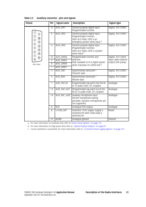
Table 2.5Auxiliary connector - pins and signalsa.For more information on hardware links refer to“Power Sense Options” on page121.b.For more information on high power drive refer to “Special Purpose Outputs” on page67.c.Can be switched or unswitched. For more information refer to “Connector Power Supply Options” on page131.Table 2.6Auxiliary connector - DC characteristicsParameterStandardTest method and conditions Comments min.typ.max.unitsDigital signals Input low level:All inputs AUX_GPI20.7V s–4VVNo hardware links fitted a.LK3 fitted.Includes AUX_GPI3 with LK1/2 fitted.Configured as emergency power senseinput.Input high level:All inputs AUX_GPI2 AUX_GPI31.7V s–1.52.6VVVNo hardware links fitted a.LK3 fitted.LK1 and/or 2 fitted.Configured as emergency power senseinput.Configured as power sense input.Input low current:All other inputs AUX_GPI2 AUX_GPI3 AUX_RXD –100–120–13b–500–1µAmAµAmANo links fitted a. Default pullups c.LK3 fitted. V s=13.8VLK1 and 2 fitted.–8V input.Default pullup resistance is 33kΩ.Configured as emerg. power sense input.Configured as power sense input.Input high current:AUX_RXDAll other inputs 110100mAµAµANo links fitted a. Default pullups c.+8V input.3.3V input.5V input.Default pullup resistance is 33kΩ.Output low level:AUX_GPIO4-7 AUX_TXD 50600200mVmVmV100µA sink current.10mA sink current.100µA sink current.Current limit occurs at 20mA typ.Output high level:AUX_GPIO4-7 AUX_TXD 3.12.4VVNo load. Default pullups c.3kΩ load.Safe DC input limits:AUX_GPI1-3 AUX_GPIO4-7 AUX_RXD AUX_TXD d –0.5–0.5–25V–10V s+0.5V s+0.5V s+0.5V s+0.5VVVVInput current must not exceed ±50mA.This is the rating of the clampingdiodes.Analogue signals DC output range:RSSI13V8_SW 09.7317.2VVSee Table2.9 on page24.Follows V s.Output switches off outside this range.DC bias:AUD_TAP_IN AUD_TAP_OUT AUX_MIC_AUD 1.42.12.91.52.33.01.62.53.1VVVNo load. Zero Rx frequency error.Via 2.2kΩ.Bias for electret microphone.Input impedance:AUD_TAP_IN AUX_MIC_AUD 502.11002.21502.3kΩkΩDC to 10kHzOutput impedance:AUD_TAP_OUT RSSI 59095060010006501050ΩΩDC to 10kHzSafe DC input limits:AUD_TAP_IN AUD_TAP_OUT d AUX_MIC_AUD RSSI d –17–0.5–17–17+17+17+17+17VVVVShort circuit-safe. Input current <±20mAa.For more information on hardware links refer to “Power Sense Options” on page121.b.It is recommended that this input is driven by a mechanical switch or an open collector/drain output.c.For more information on pullups refer to “Digital Input Lines” on page39.d.These outputs are protected against accidental input to the limits specified.22Description of the Radio Interfaces TM8000 3DK Hardware Developer’s Kit Application ManualNotes:1.Optional processing blocks are bypassed in the above specification.2.For AUD_TAP_IN and AUD_TAP_OUT specifications the following signal paths apply:Table 2.7Auxiliary connector - AC characteristicsParameterStandardTest method and conditionsCommentsmin.typ.max.unitsAUD_TAP_IN (refer to note 4)Nominal input level:T ap T3, T4, T5, T8, T12T ap T13T ap R7, R100.620.780.620.690.870.690.760.960.76V p-p V p-p V p-p Level for 60% RSD@1kHz.Level for 3kHz dev.@1kHz.Refer to note 3.Equivalent to –10dBm into 600Ω.Full scale input level 2.0V p-pFrequency response:All tap-pointsRefer to the plots inTable 2.10 and Table 2.11.Group delay - absolute:T ap T13T ap T12T ap T8T ap T5T ap T4T ap T31.81.89.611.611.711.7ms ms ms ms ms msAt 1kHz. Refer to note 2.Refer to note 1.Refer to note 1.Group delay - distortion:T ap T12 and Tap T13Refer to the plots in Table 2.12.AUD_TAP_OUTNominal output level:All Rx tap-points except R1T ap R1T ap T30.620.540.620.690.600.690.760.660.76V p-p V p-p V p-p Rload=600Ω.Level at 60% RSD@1kHz.Level at 3kHz dev.@1kHz Refer to “Microphonesensitivity ”of AUX_MIC_AUD.Equivalent to –10dBm into 600Ω.Full scale output level 2.0V p-pRload=600Ω.Frequency response:All tap-pointsRefer to the plots inTable 2.10 and Table 2.11.Group delay - absolute:T ap R1T ap R2T ap R4T ap R5T ap R7T ap R101.81.86.66.78.58.7ms ms ms ms ms msAt 1kHz. Refer to note 2.Refer to note 1.Group delay - distortion:T ap R1 and Tap R2Refer to the plots in Table 2.12.AUX_MIC_AUD Rated System Deviation NB MB WB–2.5–4.0–5.0+2.5+4.0+5.0kHz kHz kHzEIA-603BUnits are peak frequency deviation from nominal carrier frequency in kHz.Modulation frequency responseRefer to the plot in Table 2.13.EIA-603BMicrophone sensitivity 6.07.59.0mV rmsEIA-603BCaseInput Output Tap into Rx chain AUD_TAP_INRX_AUD Tap out of Rx chain Modulation at antenna AUD_TAP_OUT Tap into Tx chain AUD_TAP_IN Modulation at antenna Tap out of Tx chainAUX_MIC_AUDAUD_TAP_OUT3.For tap into the Rx path, nominal level refers to the level required to give output at RX_AUD that is same as the60% dev level from the receiver. The level specified applies at 1kHz only.4.AUD_TAP_IN uses a DC-coupled analog-to-digital converter and the bias voltage specified in Table2.6 should beused to maximise dynamic range. The DC bias is removed internally by a digital high-pass filter so the Tx carrier frequency will not be affected by any bias error. it is recommended to use external AC-coupling for applications which do not require modulation to very low frequencies.Table 2.8Auxiliary connector - data characteristicsParameterStandardTest method and conditions Comments min.typ.max.unitsSerial portBaud rate:1200, 2400, 4800,9600, 14400, 19200bit/s All UART parameters are fixedand common to all UARTsexcept for the baud ratewhich is configurable anddifferent for different modes/applicationsData bits: 8Start bit:1Stop bit:1 Parity:None Protocol:CCDI2 Flow control:Software XON/XOFF GPIODelays:I/O mirror to IOP UI key delay 50050µsmsTable 2.9RSSI voltage vs. signal strength24Description of the Radio Interfaces TM8000 3DK Hardware Developer’s Kit Application Manual。
路宝完全维修手册
路宝完全维修手册发动机概述本发动机为四缸直列水冷四冲程发动机,双顶置凸轮轴,气门机构成"V"型排列,16气门(单缸两个进气门,两个排气门).气门由曲轴通过同步链驱动凸轮轴分别开启关闭。
本发动机采用联合汽车电子有限公司匹配的多点控制喷射系统,大大降低了尾气中的有害成分含量,是完全适应新配方法规要求的绿色环保动力。
此发动机采用多点燃油喷射,包括检测发动机工况的传感器,发动机的电子控制单元(ECU)根据这些传感器发出的信号控制该系统;各执行器在ECU的控制下工作。
ECU具有燃油喷射控制,怠速控制等功能,并且,ECU还具有发生故障简化故障排除的若干故障诊断方式。
变速器参数(括号内参数为7100)DABS10-8型变速器档位速比齿数比一档 3.416(3.818) 41/12二档 1.894(2.277) 36/19三档 1.280(1.521) 32/25四档0.914(1.030) 32/35五档0.757(0.783) 25/33倒档 3.818(3.583) 42/35/11主减速器 4.389(4.705) 79/18速度表0.944 17/18最大输入转矩72N.M外廓尺寸409X392X342.7(MM)变速器倾角5度润滑油:优先选用:南方全年80W-90或85W-140;北方冬季75W-90夏季80W-90也可选用;18#双曲线齿轮油发动机************************************************************启动困难A、启动机不运转1.蓄电池电极接先处松动或电量不足拧紧或充电2.电路有断开处检查和修理3.启动机有损坏修理或更换---------------------------------------------------------B、点火系统故障1.搭铁不良修理2.线束断路或短路检查和修理3.接插件松拖或损坏修理或更换4.点火线圈损坏更换5.高压阻尼线插错接查不好或损坏调整或更换6.火花塞间隙不当积炭或烧毁调整清洗或更换----------------------------------------------------------C、供油系统的故障1.喷油器接插件插错调整2.线束断路或短路检查和修理3.接插件松脱或损坏修理或更换4.油压调节器真空管脱落破坏装上或更换5.电动燃油泵供油压力不足修理或更换6.喷油器损坏或堵塞更换或清洗7.燃油软管弯折及燃油滤清器堵塞调整或更换----------------------------------------------------------D、EMS系统故障1.主继电器或燃油泵继电器损坏更换2.电子控制单元(ECU)有故障修理或更换3.转速传感器或引线损坏修理或更换-----------------------------------------------------------E、汽缸压缩压力减小1.汽缸垫破裂更换2.气门间隙调整不当或有损坏调整修理或更换3.活塞活塞环汽缸磨损修理或更换-----------------------------------------------------------**********************************************************F、怠速过高1.ECU断电后未进行自学习熄火进行自学习2.ECU故障代码未被清除清除3.节气门无法完全回位检查和调整4.进气系统漏气检查和修理5.怠速调节器(进步电机)损坏更换6.节气门位置传感器损坏更换***********************************************************G、运转中功率不足1.加速踏板与节气门体拉线调整不当调整2.汽缸压缩压力减小检查气门火花塞汽缸垫是否渗漏气门研磨3.燃油压力调节损坏造成燃油供给不足调整或更换4.进气不足检查进气系统5.排气堵塞检查排气系统和清楚积炭6.火花塞间隙不当积炭或损坏调整清理或更换7.单缸高压阻尼线损坏更换8.点火线圈性能下降各缸点火能量不足更换9.喷油器堵塞或损坏清洗或更换10.燃油滤清器堵塞更换11.节气门位置传感器损坏更换12.电动燃油泵供油压力不足修理或更换***********************************************************H、发动机内部有敲缸声1.轴瓦磨损凸轮轴凸轮磨损更换2.曲轴连杆轴颈和活塞销磨损严重更换和修理3.活塞环损坏更换4.气门间隙不当调整5.凸轮轴曲轴止推间隙太大调整6.爆震传感器损坏更换*************************************************************I、发动机过热1.火花塞间隙不当或积炭清理或调整2.进气管松动排气管堵塞拧紧或调整3.接插件插接不好或风扇损坏调整或更换4.冷却液不足或水管堵塞补充或清理5.水泵间隙不当或损坏修理或更换6.机油不足补充7.机油路堵塞或机油泵损坏清理或更换8.汽缸垫损坏更换9.离合器滑动修理或更换10.散热器被水垢堵塞清理或更换11.节温器打不开调整或更换12.水泵皮带张紧力不足调整************************************************************ J、机油消耗量过大1.气门导套油封磨损或损坏更换2.油环磨损或损坏更换3.活塞环对口未按规定错开调整4.汽缸垫损坏更换5.气门与气门导套磨损更换6.发动机过热内压增加部分机油通气口排出检查有关部位7.油封损坏漏油更换2离合器************************************************************* K、离合器有噪音1.分离轴承磨损或损坏更换2.前输出轴轴承磨损更换3.离合器轮毂松动修理4.离合齐压盘有裂纹更换5.压盘和膜片弹簧有松动修理或更换6.离合器摩擦片有油清理或更换7.离合器减震胶棒或弹簧损坏更换************************************************************* L、离合脱离不开和空离合1.踏板行程不够或钢索空行程太大调整2.没有空行程调整3变速器、************************************************************* 变速器换档困难1.同步齿圈磨损更换2.同步齿轮磨损更换3.定位球损坏更换4.拨叉变形或不均匀磨损修理或更换4排放************************************************************* M、排放不合格1.使用了含铅的燃油造成氧传感器及三元催化器损坏更换2.点火系统故障造成缺火并长期使用将氧传感器及三元催化器损坏更换3.排气系统漏气电子控制器得不到正确的氧传感器信号造成空燃比变浓更换5消声器************************************************************* N、消声器的性能太差1.排气管接头松动拧紧2.排气支管松动拧紧3.排气支管或消声器损坏修理或更换4.消声器衬套损坏更换5.车体和消声器之间干涉修理减少接点6冷却系统************************************************************* O、风扇不动作1.电源线断开接通2.电容器熔断更换3.风扇继电器不导通更换4.水温传感器有故障检查修理或更换5.风扇电机有故障检查修理或更换************************************************************* P、风扇不停止1.风扇继电器常通更换2.水温传感器有故障检查并更换7车轮及轮胎************************************************************* 轮胎磨损快或磨损不均匀1.四个轮胎气压不均调整轮胎气压2.四个轮胎直径不同调整或更换3.车轮轴承磨损或松动更换4.轮胎摆震修理或更换5.轮胎更换不当导致不平衡调整6.前轮定位调整不良按规定调整8传动轴************************************************************* 传动轴异响1.万向节过度磨损更换2.万向节缺少润滑油加规定油脂3.差速器润滑不良加润滑油4.防尘罩破碎更换5.差速器油封漏油更换9制动系统************************************************************* 制动力不够1.制动管中制动液泄露确定泄露部位并修理2.制动盘或摩擦块有油污清洁或更换3.制动器或热找出原因并维修4.制动鼓与制动蹄接触不良修理改善接触5.制动蹄有油污或水更换6.制动蹄严重磨损更换7.制动分泵有故障修理或更换8.制动钳总成有故障修理或更换************************************************************* 制动不均(制动器工作不协调)1.制动蹄有油污或水更换2.制动鼓与制动蹄的间隙失调检查制动调整机构是否工作3.制动鼓与制动蹄的间隙失调更换4.轮胎气压左右不均均匀充压5.制动分泵有故障修理或更换6.前轮定位不良按规定调整7.同轴轮胎不一致同一轴上用同一规格轮胎8.制动管路堵塞检查制动管路是否损失如有换新件9.悬架零件松动检查所以的悬架安装10.制动钳松动检查螺栓的扭矩是否达到规定值11.制动钳故障检查制动钳是否有卡滞滑销是否正确*********************************************************** 润滑修理或更换卡钳踏板行程过大1.部分制动系统故障检查制动系统必要时修理2.制动系统中有空气(踏板软/海绵状)制动系统排气3.后制动器间隙未调好修理或更换间隙调整机构调整制动间隙4.制动蹄弯曲变形更换制动蹄5.制动蹄磨损更换制动蹄6.制动液壶内制动液不足加制动液检查系统是否泄露************************************************************* 制动器未完全分离(制动踏板松开后制动器有轻微带刹车)1.主缸活塞回程不对修理主缸2.主缸回流堵塞清洗3.制动管路堵塞检查制动管路部件是否损坏如有更换新件4.驻车制动调整不正确检查并调整好5.制动器内复位弹簧变弱或损坏更换6.驻车制动钢索不灵活或卡滞修理或更换7.制动分泵或制动钳活塞卡滞必要时修理************************************************************* 踩下制动踏板时连续跳(不是轻微跳动)1.车轮轴承损坏或松动更换车轮轴承2.后轮制动鼓失圆检查跳动修理或更换3.制动盘轴向跳动太大按说明检查制动盘修理或更换************************************************************* 制动噪声1.制动蹄磨光或制动衬片粘有杂质修理或更换制动蹄制动衬片2.制动蹄制动衬片磨损或损坏更换制动蹄制动衬片3.前轮轴承松动更换轴承4.制动底板变形或安装螺母松动更换或拧紧固定螺母************************************************************* ABS警告灯亮1.旧故障代码未被清除使用诊断仪清除旧故障代码2.ABS部件工作不良或损坏使用诊断仪故障代码按故障代码检查故障修理或更换************************************************************* 转向系统转向困难1.轮胎气压不足调整压力2.转向横拉杆接头卡住修理或更换3.前轮定位不良按规定调整************************************************************* 转向轮摆(摆动颤动或震动)1.轮胎压力不足调整轮胎压力2.车轮摆动修理或更换3.左右轮胎直径不同更换相同规格的轮胎4.轮毂螺母松动拧紧5.横拉杆接头磨损或松动更换或拧紧6.转向器安装松动拧紧7.轮胎或车轮不平衡平衡车轮或轮胎8.轮胎鼓包或撞鼓更换轮胎9.前轮定位调整不良检查前轮定位************************************************************* 转向盘自动拉向一边(汽车行车)1.轮胎磨损不均更换2.在一个轮胎上制动器抱死修理3.轮胎充气不足调整轮胎压力4.转向拉杆磨损或变形更换5.前轮定位不准按规定调整6.前悬架或后悬架零件松动弯曲或损坏拧紧或更换悬架零件7.转向器齿合不良更换************************************************************* 转向盘受到冲击(或车轮的角震动)1.轮胎充气压力过高降至规定值2.减震器性能差更换3.轮胎直径不同调整或更换4.转向横拉杆接头磨损更换5.前轮轴承磨损或损坏更换6.前轮松动拧紧7.转向盘松动拧紧螺母8.轮胎鼓包或撞包更换轮胎9.转向器转动力矩过小调整************************************************************* 轮胎磨损快或磨损不均匀1.轮胎气压不均调整轮胎气压2.轮胎直径不同调整或更换3.车轮轴承磨损或松动更换4.轮胎摆震修理或更换5.轮胎更换不当导致不平衡调整6.前轮定位调整不良按规定调整7.行驶工况不良尽量降低车速*********************************************************** 转向噪声1.螺栓螺母松动拧紧2.钢板弹簧座松动拧紧3.车轮轴承损坏或其他不良更换4.转向横拉杆磨损或卡住更换5.转向横拉杆接头润滑不足润滑或更换************************************************************* 转向游隙太大1.车轮轴承磨损更换车轮轴承2.转向器安装螺栓松动拧紧或修理3.转向器间隙调整不良检查或调整4.转向横拉杆接头磨损或松旷更换接头************************************************************* 回位不良1.转向横拉杆接头卡住更换接头2.转向柱卡住修理或更换3.转向器润滑不良润滑4.前轮定位不准检查并调整5.转向器间隙调整不良检查并调整小齿轮扭矩6.轮胎压力不足调整压力************************************************************* 转向横拉杆噪声异常1.转向横拉杆接头磨损卡位或松动更换更拉杆接头2.减震器或安装件损坏更换或修理3.前稳定杆松动拧紧螺栓或更换衬套4.车轮螺母松动拧紧5.悬架螺栓或螺母松动拧紧悬架螺栓或螺母6.车轮轴承损坏或其他不良更换7.悬架弹簧损坏更换*********************************************************** 11悬架系统************************************************************* 调整高度低或不均1.弹簧折断或扭曲更换2.超载检查载荷3.弹簧规格不对更换************************************************************* 乘坐不舒服减震器有故障更换************************************************************* 悬架压到底部1.超载检查载荷2.减震器有故障更换3.弹簧规格不对更换*********************************************************** 12车速里程表************************************************************* 指示错误1.车速传感器故障更换2.变速器故障(润滑油不足或传动齿轮磨损)修理或更换3.车速里程表故障更换4.车速表指针卡滞修理5.接车速传感器的先束插接件接触不良修理*************************************************************没有指示1.仪表电源线断路修理2.车速传感器故障更换3.车速里程表故障更换4.车速表指针卡死修理5.接车速传感器的线束故障(正线断路或短路/搭铁线断路/信号线断路或短路)修理***********************************************************13发动机转速表*************************************************************指示错误1.发动机曲轴传感器故障更换2.发动机ECU故障更换3.信号输入线插接件接触不良修理4.转速表故障更换5.转速表针卡滞修理*************************************************************没有指示1.仪表电源线断路修理2.发动机曲轴传感器故障更换3.发动机ECU故障更换4.信号输入线断路修理5.转速表故障更换6.转速表指针卡死修理14燃油表************************************************************* 指示错误1.燃油传感器故障(浮子卡滞)修理或更换2.线束插接件接触不良修理3.接燃油传感器的线束搭铁修理4.燃油表故障更换5.燃油表针卡滞修理************************************************************* 没有指示1.仪表电源线断路修理2.燃油传感器故障(电阻开路)更换3.接燃油传感器的线束断路修理4.燃油表故障更换5.燃油表针卡死修理15水温表************************************************************* 指示错误1.水温传感器故障更换2.线束插接件接触不良修理3.接水温传感器的线搭铁修理4.水温表故障更换5.水温表指针卡滞修理************************************************************* 没有指示1.仪表电源线断路修理2.水温传感器故障(电阻开路)更换3.接水温传感器的线断路修理4.水温表故障更换5.水温表指针卡死修理17空调系统无热风或热风不足1.控制机构损坏或操作不正确修复控制机构2.阀们损坏更换阀们3.暖风导管堵塞检查并修复4.加热芯体泄露或堵塞更换加热芯体5.热水管泄露或堵塞更换水管++++++++++++++++++++++++++++++++++++++++++++++++++++++++++++++++++++++ +++++++++++++++++冷气不足暖风电机工作正常下1.通风口堵塞检修2.蒸发器结霜检修3.储液器过滤层堵塞更换储液器4.暖风导管堵塞检修暖风机电机故障下1.开关故障更换或修理2.电阻值不正常更换3.熔断丝熔断检查并修复4.线路连接故障检查并修复5.电机故障更换电机6.叶轮损坏更换叶轮+++++++++++++++++++++++++++++++++++++++++++++++++++++++++++++++++++++++++++++++++++++++空调不工作1.熔断器熔断更换熔断器2.线束接头不良修理线接头3.制冷剂不足或过量填充制冷剂修理泄露处或者释放一部分制冷剂4.空调压缩机继电器故障更换空调压缩机继电器5.空调压力开关故障更换压力开关6.空调压缩机电磁离合器故障更换空调压缩机7.压缩机过热保护开关故障更换压缩机过热保护开关8.空调开关不良更换空调开关9.风速开关不良更换风速开关10.发动机ECU不良更换发动机ECU++++++++++++++++++++++++++++++++++++++++++++++++++++++++++++++++++++++ +++++++++++++++++暖风电机不转1.熔断器熔断更换熔断器2.线接头不良修理线接头3.暖风机电机不良更换暖风机电机4.风速开关不良更换空调控制板组件5.调风速电阻不正常更换调速电阻6.叶轮故障更换叶轮++++++++++++++++++++++++++++++++++++++++++++++++++++++++++++++++++++++ +++++++++++++++++暖风电机旋转不停风速开关故障更换风速开关哈飞汽车诊断头位置、电脑、引擎、及适用系统哈飞路宝7110:OBD诊断头。
CA498、CA4D32系列柴油机维护手册基础
电起动(12V)
润滑方式
强制飞溅润滑
机油压力
kPa
工作油压200-490
最低空载 稳定转速
(r/min)
700~750
全负荷最大排气烟度
(FSN)
≤4.0
≤3.0
≤3.0
≤3.0
排气温度
(℃)
≤700
净重
(kg)
245
260
260
265
噪声
dB(A)
≤115
外型尺寸(长×宽×高)
684×603×722
7. 系统图………………………………………………………………………………………………………………………………………41
8. 故障及排除方法……………………………………………………………………………………………………………………………46
9. 技术参数…………………………………63
10. 柴油机主要专用件清单……………………………………………………………………………………………………………………70
11. 保用细则……………………………………………………………………………………………………………………………………71
12. 附录…………………………………………………………………………………………………………………………………………71
2.3.4 CA4D32-12发动机
备忘录
3.发动机的操作说明
3.1 首次开机前的准备……………………………………………………………………………………………………………………………19
3.1.1 加注机油……………………………………………………………………………………………………………………………………19
宝来发动机检修

第四章BORA宝来发动机控制检修第一节发动机自诊断一、自诊断技术数据控制单元识别码接好VAG1551或V.A.G1552或VAS5051后,选择发动机电控单元,即可显示控制单元版本号。
使用V.A.G1551/1552 或VAS5051时的可选功能下表中列出了可选功能的条件功能条件V.A.G1551/1552 或VAS501上的功能打开点火开关,但不起动发动机发动机怠速车在行驶中01查询控制单元版本号是是是02查询故障存储器是1)是是03执行元件自诊断是否否04基本设定2)是是是05清除故障存储器是是是06结束输出是是是07控制单兀编码是否否08读取测量数据块是是是10自适应是否否1)只有在打开点火开关,但不起动发动机时进行(先操纵起动机至少6秒钟)。
2)只在完成下述工作后才进行,更换发动机控制单元、节气门控制单元、发动机或断开蓄电池。
二、组合仪表上EPC灯的作用“EPC”是一缩写,意为“电子功率控制”,也就是电子油门(E-Gas)EPC警报灯的安装位臵在发动机运转时,如电子油门发生故障,组合仪表将接通EPC警报灯(该故障可查故障表),同时,发动机控制单元故障储存器会记录该故障。
功能检查打开点火开关,EPC警报灯应亮。
如果EPC警报灯不亮,检查组合仪表和EPC警报灯:如果EPC警报灯亮,起动发动机,使之怠速运转;几秒钟后,EPC警报灯应熄灭。
如果EPC警报灯不熄灭,杳询故障存储器,排除故障后清除故障存储器.仅指AUM发动机:读出状态代码,若已清除了故障存储器或断开了发动机控制单元供电,必须制作新的状态代码。
废气警报灯的作用仅指AUM发动机如果发动机控制单元识别出与废气相关的故障,该故障就由废气警报灯来指示废气警报灯接通后有闪亮和长亮两状态,不管哪种状态出现,均应查询故障存储器。
闪亮:表示在该行驶状态时,出现了可造成催化净化器损坏的故障,这时,应降低功率来驾车。
长亮:表示出现了导致废气质量变差的故障,应查询发动机控制单元或变速器控制单元的故障存储器。
宝来BORA A4 维修手册---数据流
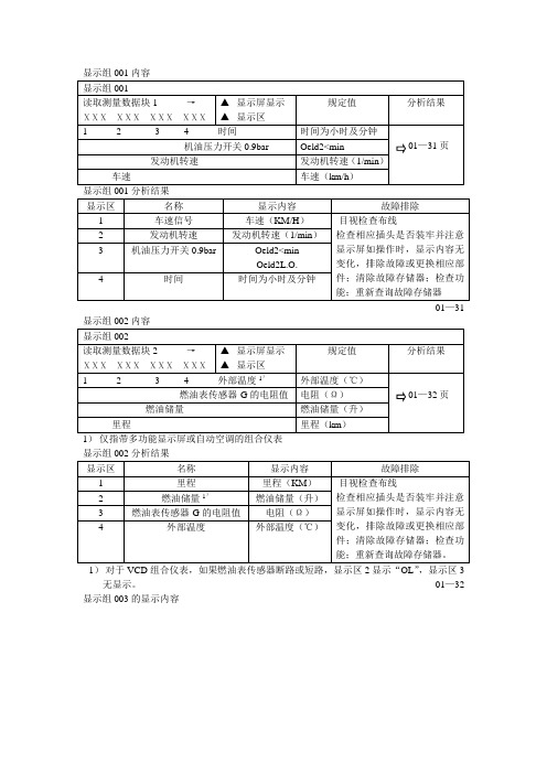
显示组001内容01—31显示组002分析结果1)对于VCD组合仪表,如果燃油表传感器断路或短路,显示区2显示“OL”,显示区3无显示。
01—32 显示组003的显示内容1) 空表示显示区无显示1) 显示的是冷却液实际温度,在18℃—107℃之间时,组合仪表上总显示90℃。
01—33 显示组050的显示内容自适应自适应可修改并存储下述内容SIA )复位Highine 型组合仪表) 可用相应通道号选择相应功能(见自适应表)。
说明:在改变了自适应值或结束了自适应通道后,如想选择另必须重新选择功能“10-自适应”。
显示组一览表显示组001的显示内容显示区002的显示内容01—981)仅指带多功能显示或自动空调的组合仪表显示组002的分析结果1)如果燃油传感器断路,区2显示“OL ”,显示区3显示510Ω;如果燃油表传感器短路,显示区2显示“OL ”,显示区3显示0Ω。
01—99 显示组003的显示内容 1) 空表示显示区无显示2) 打开点火开关后, 如系统有故障,机油油面警报灯闪亮5秒钟 01—100 显示组003分析结果1)如果冷却液温度的实际值在约75℃-107℃之间(对于有待性曲线冷却功能的车为75℃-115℃),组合仪表总显示90℃。
2)打开点火开关后,如系统有故障,机油油面警报灯闪亮5秒钟。
显示组050的显示内容对于不存在的控制单元,相应显示区中无显示以下的测量数据表示所有连在数据总线上的控制单元状态。
根据组合仪表的生产厂不同(VDO或MMO)显示区的内容也不同。
显示组125的显示内容1)仅指VDO,对于Motometer则在显示组126,显示区2 01—10201—103显示组126的分析结果自适应 01—105 自适应可执行并存储下述改为:SIA)自适应SIA )复位Midline 及Highine 型组合仪表)可用相应通道号选择相应功能(见自适应表) 说明:在改变了自适应值或结束了自适应通道后,好想选择另一个自适应通道,必须重新选择功能“10-自适应”。
宝来TDI轿车柴油发动机启动困难的故障检修方案设计

目录第一部分设计任务与调研 (1)第二部分设计说明 (2)第三部分设计成果 (11)第四部分结束语 (12)第五部分致谢 (13)第六部分参考文献 (14)第一部分设计任务与调研一、毕业设计的主要任务1掌握宝来TDI柴油发动机结构、工作原理分析;2.了解宝来TDI柴油发动机启动困难的故障原因分析;3.完成宝来TDI柴油发动机启动的故障诊断方案设计。
二、设计的思路、方法等1.通过检索相关专著、论文、汽车维修手册、培训材料等资料, 收集与宝来TDI柴油发动机启动困难毕业设计相关的材料。
2.经过分析、归纳、整理, 系统分析宝来TDI柴油发动机启动故障原因。
3.进行现场实践, 对宝来TDI柴油发动机进行实车研究。
4.开展方案设计, 通过系统分析法和现场验证, 比较各种方案, 逐步优化设计方案、明确设计故障诊断方案。
5.应用检验, 验证故障分析诊断思路的逻辑性和有效性;结合宝来TDI柴油发动机维修实践进行检验, 进一步修改完善设计, 验证科学性与实用价值。
三、与本课题相关的资料参考以下书籍【1】李玉茂.宝来、捷达轿车故障实例与分析.北京: 机械工业出版社, 2008 【2】徐西安.范志丹等.柴油发动机构造与维修.北京: 北京理工大学出版社, 2011 【3】孙凤英等.宝来轿车维修手册.北京: 机械工业出版社, 2003【4】邵恩坡等.柴油车使用维护.广州: 广东科技出版社, 2004【5】张永波.汽车故障诊断与维修.北京: 北京邮电大学出版社, 2013【6】鲁植雄.刘奕贯.大众车系维修体验.北京:电子工业出版社, 2012四、调研的目的和总结通过调研,收集足够的、真实的和有效的专业信息,为本次毕业设计提供充分的理论基础及参考依据。
调研的部门为汽车企业、汽车公司、汽车专业人士等一切与本次毕业设计相关的单位或个人,获得的信息有些是学术性的, 也有些是实用性的。
第二部分设计说明第1章宝来TDI柴油机的结构和工作原理1.1宝来TDI柴油发动机概况宝来TDI柴油发动机采用了最新的高压燃油喷射技术——泵喷射系统。
BWH1.6L宝来轿车发动机检修分析
柴油发动机维修指南说明书

We don’t know much about alli-gator wrestling (which looks dangerous) or mud wrestling(which looks like tons o’ fun), but we do know something about diesel wrestling.We say “wrestling” because work-ing on diesel engines is different from working on gasoline engines—you don’t get as many in your bays, so you’re less familiar with them. This article is meant to change that. N exttime you “go to the mat” with a dieselengine, you may be able to demon-strate a few new “holds.”As you know, a diesel engine requires no spark plugs to fire the fuel, although glow plugs are typically used to assist engine starts in cold weather. Often, the fuel accumulates slightly before light-off occurs. This is called the delay stage .Once the delay stage concludes, the fu-el mixes with the hot compressed air in the cylinders and ignites, causing crunching blows to occur inside the en-gine. It ’s because of these crunching blows, plus the fact that the engine pro-duces far greater cylinder pressuresthan its gasoline-fed cousin, that the diesel has long been the burly power champ that produces high torque.Two Cummins EntriesSeveral contenders have climbed into the ring on the diesel light truck card.One is the Dodge Ram truck ’s 24-valve Cummins turbo diesel, an inline Six. Featuring big breathing, this en-gine produces 245 hp with the six-speed manual transmission, or 235 hp for automatics. Peak torque of 505 ft-lb comes in at 1600 to 2300 rpm.Cummins says the 24-valve cylin-WRESTLING WITH MODERN DIESELSB Y T HOMAS M ARCYWinning a bout with a diesel engine means using some heavy-duty skills. And as with any tough match, it pays to know the strengths and weaknesses of your opponent.der head design increases airflow and improves low-speed performance.The head also features vertical, cen-tered injection nozzles, which are claimed to boost combustion efficien-cy, cleanliness and fuel economy.Weigh in some electronic fuel control and you ’ve got a tough opponent.A diesel engine ’s fuel injection sys-tem must possess several characteris-tics to deliver maximum perfor-mance. These include accurate injec-tion control, high-pressure atomiza-tion, fast fuel ignition and fuel tem-perature adjustment capability.Fuel ’s fiery entry into the cylinders in the Cummins comes via a Bosch VP44 electronic injection pump and electronically controlled timing. First,the engine is cranked up for the match with an electric-powered lift (or supply) pump. Fuel flow begins as the lift pump pulls fuel from the tank and delivers it to the injection pump.As the engine spins over, the rotary,high-pressure injection pump is driv-en at half the engine speed by a sim-ple front gear train. This simplicity helps cut operating noise.The Cummins-developed ECM re-ceives information from various sensors and controls on the engine, then trans-lates that info into specific fuel quantity and timing commands that are sent to the injection pump metering control.Note that the injection pump used on earlier (1994-98) Cummins-equipped Dodge turbo diesel pickups is a Bosch P7100 inline design —what we sometimes call the jerk pump .The cam-operated six-plunger pump in the jerk pump sends fuel to the in-jector nozzles. The newer VP44, how-ever, is a rotary job with the ability to vary fuel and injection timing basedP h o t o : P a u l W e i s s l e ron input from the ECM. This pump incorporates a fuel pump control module (FPCM), which contains fu-eling, timing and diagnostic data. The FPCM communicates with the ECM to obtain information on desired fuel-ing and timing. The FPCM responds by consulting the fueling data and timing in its memory, then commands fueling and timing solenoids.The VP44 has a fuel temperature sensor inside it. The pump also con-tains a speed sensor that gives the FPCM information on the position and speed of the pump shaft. A crank-shaft reference pulse that marks TDCof cylinder No. 1 is also sent once every pump revolution. By comparing this reference pulse from the ECM to the position signal from the speed sensor, the FPCM can reference the pump ’s position to that of the engine.This allows the FPCM to adjust pump timing to compensate for small posi-tion differences between the fuel pump shaft and the engine cam. If the difference becomes too great, a fault is logged in the FPCM.The FPCM controls the timing and fueling through two solenoids located in the pump. The timing solenoid controls the position of a cam ring in-side the pump by varying internal transfer pump pressure to a cam ring piston. The cam ring has evenly spaced lobes around its inner diame-ter. The pumping plungers ride on rollers that rotate around inside this ring. The rollers follow the inner di-ameter of the ring and push the pumping plungers inward whenever a cam lobe is encountered. This builds injection pressure on the fuel trapped between the plungers. By rotating the cam ring with the timing solenoid,the FPCM is able to advance and re-tard the injection timing by makingthe rollers contact the cam lobes ei-ther earlier or later in their rotation.As its name implies, the fuel solenoid in the pump meters fuel to the injec-tors. It does this by opening a metering valve to allow fuel from the supply pump to flow into the pumping cham-ber. Once this chamber is charged with fuel, the solenoid valve closes, trapping the fuel in the chamber and allowing injection pressure to build.The fuel is routed to the correct in-jection nozzle via the pump distributor head. A port on the distributor rotor aligns with one of the six pump dis-tributor head outlet ports to distribute fuel to a given nozzle. In the cylinder head, the high pressure opens the in-jector nozzles, allowing fuel to pass in-to the combustion chamber. Once the desired amount of fuel is injected, the solenoid valve opens, causing the pres-sure in the pumping chamber to bleed down, which ends injection. The injec-tion nozzle then snaps shut.When the high-pressure fuel reaches the nozzle, the pressure lifts the needle valve against the spring ’s preset “popping ” tension. At the de-sired pressure, the nozzle pops open to let the fuel spray into the combus-tion chamber. A minor fuel leak past the nozzle needle valve enters the fu-el drain manifold in the cylinder head. The fuel in the manifold then exits at the rear of the cylinder head and is routed to the fuel tank. Fuel return from the injection pump is al-so routed back to the tank.Breathing and BelchingBoth Cummins engines —the older Bosch-equipped P7100 and the newer VP44—feature direct injection, sans precombustion chambers. Cummins claims that direct injection produces more power than precombustion chamber-equipped engines, while lowering internal heat stresses. High compression heat and fuel swirl for good combustion develop in the pis-ton ’s symmetrical combustion bowl.In the late-model Cummins turbo diesel, the valvetrain has wider lobes on the tappet face and cam, with longer push tubes. To reduce camshaft wear, an electric lift pump eliminates the need for a mechanical lift pump lobe. The standard valve springs are compatible with engine braking equipment. Top off the en-gine with an engine-matched Holset turbocharger and wastegate and you have a unit ready to rumble. For Cummins, a no-smoke entry into the fray is gained with an Integrated Air Intake Grid Heater. Using this method, white smoke is eliminated and cold-starting is improved. After warmup, compression and combus-tion efficiencies are improved by pro-viding aftercooled air to the engine.WRESTLING WITH MODERN DIESELSFor Dodge Ram trucks, the 24-valve Cummins diesel provides improved block strength and durability, with reduced noise. Also, the water pump, oil pump, cooler housings and coolant bypass are all integrated to eliminate potential leak points.P h o t o : T h o m a s M a r c yAlso, new electronic devices allow monitoring of critical engine data and diagnostic information from the ECM.For example, with the RoadRelay 4(RR4) system, you can tap into the ECM while driving. Then if a problem develops on the road, the system will display the appropriate fault code. Al-so, RR4 can remind the driver when service is due on specific items and can record up to 12 service events.Also new for the Cummins 24-valve turbo diesel is QuickCheck II, a diag-nostic read-only application that runs on Palm devices and lets you view such items as engine sensor and diagnostic information, including boost pressure,oil pressure, fuel rate, percentage en-gine load, engine hours, output torque and intake manifold pressure. The QuickCheck II kit contains a custom data link adapter, cables, connectors and the diagnostic software applica-tion. Load the software, plug it in and you can view data in real time or download it to your shop PC.Ford’s Power StrokeFord enters the ring with an old hand, but with new tricks. In its Pow-er Stroke Garrett-turbocharged diesel, such as found in an F-250 we recently drove, a mechanical fuel pump nests in the valley behind the fuel filter with its plunger riding on a special engine cam lobe.In older models, the feed pump uses a diaphragm to draw fuel from the tank while a piston-type positive displace-ment pump increases the 4 to 6 pounds of pressure to around 50 psi, regulated by a spring and plunger in the filter housing. The 50 psi is delivered to the lower chamber inside the injector through a common rail passage in the cylinder head. The tiny fuel chamber plunger ’s oil-pressure-driven head is seven times the size of the bottom of the plunger, where the fuel is delivered.The head forms the chamber floor that receives a burst of high oil pressure.This happens as an electrical solenoid valve opens and lets the pressure in.The high oil pressure pulse drives the plunger down, multiplying the pressure by a factor of seven at the injector tip. The trapped fuel blows outthe injector tip and into the cylinder.The PCM operates the injector so-lenoids through an injector driver module. The fuel comes to the sole-noids from an injection control pres-sure sensor, a sensor in the oil rail at the front of the driver ’s side head. An injection pressure regulator (IPR)rides in the high-pressure oil pump.This pump mounts similar to the old-er-design injection pump.The fuel enters both the left and right cylinder head high-pressure feed hoses. During a cold start, the high-pressure oil pump receives unfiltered oil from the low-pressure lubrication pump through the left-side valve lifter oil galley and through the antidrainbackDiesel engines need and consume large quantities of air . Always check the airfilter and examine the manometer gauge to look for restrictions.GM growls in V8 style with the new Duramax 6600. The engine features many aluminum components and an electronic common rail fuel system.P h o t o : T h o m a s M a r c ycheck valve. Once the engine starts, or during warm engine starts, the check valve closes and the high-pressure oil pump receives filtered oil from the pump reservoir. The high-pressure pump then supplies the oil under ex-tremely high pressures through the left and right pressure rails. A relief valve in the high-pressure oil pump regulates the available pressure.The control pressure actually deliv-ered to the oil rails is regulated elec-tronically by an injector control pres-sure (ICP) regulator, controlled by the PCM. Once in the oil rail, the oil is fed to the head ’s fuel injector bores through four galleys drilled and ma-chined in the cylinder head. The high-pressure oil then activates the fuel in-jectors based on PCM commands.The GMC & Chevy T ag T eamGMC and Chevrolet enter the ring with a new 6.6-liter turbocharged diesel V8called the Duramax 6600. Although no lightweight in power, the Duramax weighs only 836 pounds. It uses alu-minum extensively in such key compo-nents as the cylinder heads, crankcase,accessory drive brackets, intake mani-fold and flywheel bellhousing. The en-gine is available in 2500 HD and 3500GMC Sierras, and in Chevrolet Silvera-do pickups and chassis cabs.The Duramax cylinder head is made of gravity-cast aluminum and has four valves per cylinder. Each fuel nozzle islocated in the center of the combustion chamber in a stainless-steel holder. The valve arrangement forms a twisting in-take airflow. The intake ports are de-signed to maximize tangential flow for optimum intake swirl. In this head, ade-quately and evenly cooling the valve seats helps minimize any change in the valve gap.The Duramax fuel system has a sup-ply pump, a function block, common rails and injectors. An eccentric shaft drives the three-plunger supply pump,which is driven at crankshaft speed. The pump ’s inlet has a gear-type feed pump and a rail pressure control valve, which is governed by a sensor attached to the function block, on the high-pressure side. The valve is controlled in response to driving conditions. Each injector has a PCM-controlled solenoid in the injec-tor ’s upper portion.According to GM, one advantage of a common rail system is that injection pressure can be raised regardless of en-gine speed. This means the size of the nozzle hole in the injector can be small,which when used in conjunction with high-pressure injection, makes for a fin-er spray and faster combustion. This, by the way, makes a good case for offering timely filter services.WRESTLING WITH MODERN DIESELSWhen servicing a diesel engine, always check the maker’s specs to see what type of oil and fuel filters the engine uses. Because of the stresses of compression-ig-nition, diesels require oil with a unique lubricationcharacter and additive package.Don’t let your customer get pinned to the mat. Battery condition is a very im-portant part of any diesel’s performance, especially during cold-weather months when glow plugs help supply initial combustion chamber heat.P h o t o s : T h o m a s M a r c yThe Duramax 6600 is a relatively high-speed engine as far as diesels go,with a rated speed of 3100 rpm. Faster combustion makes possible shorter in-jection times, which means optimum fuel economy and exhaust emissions even at those higher speeds.Using short-duration, high-pressure injection improves performance in the final exhaust emissions rounds. Howev-er, because there are higher levels of NO X (oxides of nitrogen) with high-pressure injection at the start of the process, injection timing must be re-tarded. But GM says that if the timing is retarded without pilot injection, NO X reduction is limited while particulate matter increases. GM claims that pilot injection overcomes these limitations.Injecting a very small pilot amount of fuel before TDC makes it easier for the main injection to ignite. This makes it possible to retard injection timing and reduce both NO X and particulate levels.Another benefit GM claims for pilot ignition is reduced noise. Generally,combustion noise becomes louder as in-jection pressure increases. According to GM, pilot injection makes it possible to prevent a rapid increase in injection pressure during main injection, which greatly reduces diesel knock.The engine management system and control module of the Duramax are ba-sically the same as with gasoline en-gines, with vehicle-related control items also being similar. However, the com-mon rail system required developingnew software for diesel injection control items. Other new software was devel-oped for self-diagnostic items, such as injection volume, injection timing, pilot injection control, rail pressure control and injector dwell. The ECM drives the injectors by way of an electronic driver unit (EDU), which also senses and ig-nores abnormal injection requests. The engine management system also per-forms all OBD II functions.In servicing these new diesel engines,you can easily see that a technician first needs to know the basic operation of these “oil-burners.” But he must also know the quirks applicable to each powerplant. Also, training in the DTCs that an ECM/PCM can throw into the ring becomes very important.You ’d be well-advised to get a ring-side seat and do some serious manual studying on the art of diesel wrestling.Who knows? You could be called on forthe next match!Always check for proper turbocharger and wastegate function. Although tucked far beneath the cowl on this Ford pickup truck, a simple vacuum pump test can reveal a wastegate servo knocked out of the match.With a stumbling Cummins-equipped Dodge, some technicians crack open an in-jection nozzle line to check for cylinder power output. Instead, we suggest using a contact pyrometer on the exhaust manifold to isolate the offending cylinder .。
宝来BORA A4 维修手册---数据流

显示组001内容01—31显示组002分析结果1)对于VCD组合仪表,如果燃油表传感器断路或短路,显示区2显示“OL”,显示区3无显示。
01—32 显示组003的显示内容1) 空表示显示区无显示1) 显示的是冷却液实际温度,在18℃—107℃之间时,组合仪表上总显示90℃。
01—33 显示组050的显示内容自适应自适应可修改并存储下述内容SIA )复位Highine 型组合仪表) 可用相应通道号选择相应功能(见自适应表)。
说明:在改变了自适应值或结束了自适应通道后,如想选择另必须重新选择功能“10-自适应”。
显示组一览表显示组001的显示内容显示区002的显示内容01—981)仅指带多功能显示或自动空调的组合仪表显示组002的分析结果1)如果燃油传感器断路,区2显示“OL ”,显示区3显示510Ω;如果燃油表传感器短路,显示区2显示“OL ”,显示区3显示0Ω。
01—99 显示组003的显示内容 1) 空表示显示区无显示2) 打开点火开关后, 如系统有故障,机油油面警报灯闪亮5秒钟 01—100 显示组003分析结果1)如果冷却液温度的实际值在约75℃-107℃之间(对于有待性曲线冷却功能的车为75℃-115℃),组合仪表总显示90℃。
2)打开点火开关后,如系统有故障,机油油面警报灯闪亮5秒钟。
显示组050的显示内容对于不存在的控制单元,相应显示区中无显示以下的测量数据表示所有连在数据总线上的控制单元状态。
根据组合仪表的生产厂不同(VDO或MMO)显示区的内容也不同。
显示组125的显示内容1)仅指VDO,对于Motometer则在显示组126,显示区2 01—10201—103显示组126的分析结果自适应 01—105 自适应可执行并存储下述改为:SIA)自适应SIA )复位Midline 及Highine 型组合仪表)可用相应通道号选择相应功能(见自适应表) 说明:在改变了自适应值或结束了自适应通道后,好想选择另一个自适应通道,必须重新选择功能“10-自适应”。
大众汽车2.0升16V ABF发动机维修手册说明书

2.0 tsi engine review. Vw 2.0 tsi engine repair manual.
2.0 tห้องสมุดไป่ตู้i engine code. What is vw 2.0 tsi engine. 2.0 tsi engine repair manual. Problems with vw 2.0 tsi engines. Is the 2.0 tsi a good engine. Vw 2.0 tsi engine manual.
Volkswagen logo Title File Size Download Link Volkswagen Body Collision Repair Manual.pdf 943.4kb Download Volkswagen cabriolet cruise control wiring schematic.png 29.3kb Download Volkswagen Engine 2.0 Litre 16V ABF Repair Manual – Cooling – 2.0-16V ABF.pdf 2Mb Download Volkswagen Engine 2.0 Litre 16V ABF Repair Manual – Crankshaft assembly – 2.0-16V ABF.pdf 5.2Mb Download Volkswagen Engine 2.0 Litre 16V ABF Repair Manual – Cylinder head – 2.0-16V ABF.pdf 4.2Mb Download Volkswagen Engine 2.0 Litre 16V ABF Repair Manual – Engine unit.pdf
柴油机维修手册
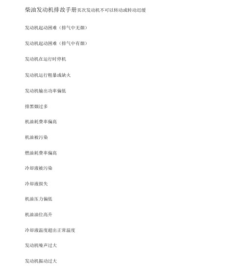
柴油发动机排故手册页次发动机不可以转动或转动迟缓发动机起动困难(排气中无烟)
发动机起动困难(排气中有烟)
发动机在运行时停机
发动机运行粗暴或缺火
发动机输出功率偏低
排黑烟过多
机油耗费率偏高
机油被污染
燃油耗费率偏高
冷却液被污染
冷却液损失
机油压力偏低
机油油位高升
冷却液温度超出正常温度
发动机噪声过大
发动机振动过大
发动机不可以转动或转动迟缓
发动机起动困难(排气中无烟)
发动机起动困难(排气中有烟)
发动机输出功率偏低
排黑烟过多
机油耗费率偏高
机油被污染
燃油耗费率偏高
冷却液被污染
冷却液损失
机油压力偏低
机油油位高升
冷却液温度超出正常温度
发动机噪声过大
发动机振动过大。
柴油机维修手册
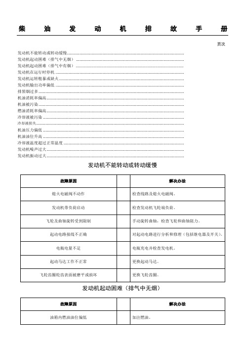
柴油发动机排故手册页次发动机不能转动或转动缓慢.......................................................................................................发动机起动困难(排气中无烟) ...............................................................................................发动机起动困难(排气中有烟)........................................................................................................发动机在运行时停机 .................................................................................................................发动机运转粗暴或缺火..............................................................................................................发动机输出功率偏低 .................................................................................................................排黑烟过多................................................................................................................................机油消耗率偏高.........................................................................................................................机油被污染................................................................................................................................燃油消耗率偏高.........................................................................................................................冷却液被污染 ............................................................................................................................冷却液损失..................................................................................................................................机油压力偏低 ............................................................................................................................机油油位升高 ............................................................................................................................冷却液温度超过正常温度 ..........................................................................................................发动机噪声过大.........................................................................................................................发动机振动过大.........................................................................................................................发动机不能转动或转动缓慢发动机起动困难(排气中无烟)发动机起动困难(排气中有烟)发动机在运行时停机发动机运转粗暴或缺火发动机输出功率偏低排黑烟过多机油消耗率偏高机油被污染燃油消耗率偏高冷却液被污染冷却液损失机油压力偏低机油油位升高。
宝来TDI维修手册

宝来TDI维修手册: .95 KB)011.jpg (219.62 KB)012.jpg (154.97 KB)013.jpg (208.32 KB)014.jpg (214.47 KB)015.jpg (214.46 KB)2007-2-23 01:47 , 阅读权限: 10017.jpg (216.13 KB)2007-2-23 01:47 , 阅读权限: 10018.jpg (226.08 KB)2007-2-23 01:47 , 阅读权限: 10019.jpg (235.03 KB)2007-2-23 01:47 , 阅读权限: 10:附件020.jpg (274.8 KB)2007-2-23 01:50 , 阅读权限: 10021.jpg (289.59 KB)2007-2-23 01:50 , 阅读权限: 10022.jpg (311.98 KB)2007-2-23 01:50 , 阅读权限: 10023.jpg (354.29 KB)2007-2-23 01:50 , 阅读权限: 10024.jpg (275.57 KB)2007-2-23 01:50 , 阅读权限: 10025.jpg (216.64 KB)2007-2-23 01:50 , 阅读权限: 10026.jpg (219.37 KB)2007-2-23 01:50 , 阅读权限: 10027.jpg (229.18 KB)2007-2-23 01:50 , 阅读权限: 10028.jpg (281.71 KB)2007-2-23 01:50 , 阅读权限: 10029.jpg (72.59 KB)2007-2-23 01:50 , 阅读权限: 10:附件030.jpg (206.47 KB)2007-2-23 02:15 , 阅读权限: 10031.jpg (208.02 KB)2007-2-23 02:15 , 阅读权限: 10032.jpg (246.29 KB)2007-2-23 02:15 , 阅读权限: 10033.jpg (190.35 KB)2007-2-23 02:15 , 阅读权限: 10034.jpg (196.67 KB)2007-2-23 02:15 , 阅读权限: 10035.jpg (254.34 KB)2007-2-23 02:15 , 阅读权限: 10036.jpg (221 KB)2007-2-23 02:15 , 阅读权限: 10037.jpg (268.65 KB)2007-2-23 02:15 , 阅读权限: 10038.jpg (270.87 KB)2007-2-23 02:15 , 阅读权限: 10039.jpg (245.34 KB)2007-2-23 02:15 , 阅读权限: 10:附件040.jpg (205.83 KB)2007-2-23 02:20 , 阅读权限: 10041.jpg (212.75 KB)2007-2-23 02:20 , 阅读权限: 10045.jpg (247.52 KB)2007-2-23 02:20 , 阅读权限: 10046.jpg (197.02 KB)2007-2-23 02:20 , 阅读权限: 10047.jpg (227.42 KB)2007-2-23 02:20 , 阅读权限: 10048.jpg (230.51 KB)2007-2-23 02:20 , 阅读权限: 10049.jpg (224.26 KB)2007-2-23 02:20 , 阅读权限: 10。
11020217-于庆成-一汽大众宝来发动机常见故障诊断与检修
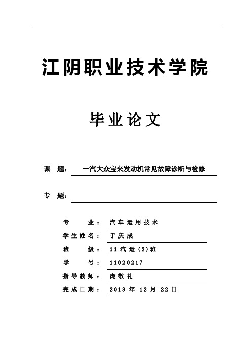
江阴职业技术学院毕业论文课题:一汽大众宝来发动机常见故障诊断与检修专题:专业:汽车运用技术学生姓名:于庆成班级:11汽运(2)班学号:11020217指导教师:庞敬礼完成日期:2013年12月22日摘要随着社会的进步以及生活水平的不断提高,人们对汽车这个代步工具的要求也越来越高,不同汽车发动机的性能也存在着差异。
我们也应当重视汽车发动机的故障诊断与检修。
本论文主要是对一汽大众宝来发动机的故障诊断与检修进行阐述,其常见故障主要有起动困难、怠速不稳、动力不足、异响等。
通过对发动机的故障现象和故障原因分析,从而进一步对发动机进行详细故障诊断。
本文还对一汽大众宝来发动机的故障诊断与检修进行了一系列的案例分析,例如,一汽大众宝来1.8发动机油耗大的故障诊断,一汽大众宝来1.6L发动机熄火的故障案例分析等,通过这些案例分析可以更直观地详解宝来发动机的故障诊断与检修流程,对一汽大众宝来发动机的故障诊断与检修有了更深刻的了解和更清楚的认识。
关键词:宝来发动机;故障;诊断;检修AbstractWith the progress of the society and the continuous improvement of living standards, people also more and more high to the requirement of the automobile transport, different car engine performance differences exist. We should also attach importance to automobile engine fault diagnosis and maintenance.This paper is mainly to faw-vw baolai engine fault diagnosis and maintenance and its common faults are starting difficulty, idle instability, underpowered, sound, etc. Through the analysis of the fault phenomenon and the cause of the problem of engine, thus further fault diagnosis of engine in detail. This article also for faw V olkswagen baolai engine fault diagnosis and maintenance carried out a series of case studies, for example, faw-vw baolai 1.8 fault diagnosis of engine fuel consumption big, faw-vw baolai 1.6 L engine fault case analysis and so on, through the case analysis can more intuitively, rounding the baolai engine fault diagnosis and maintenance process, the faw V olkswagen baolai engine fault diagnosis and maintenance have a deeper understanding and more clear.Key words: baolai engine; Fault; Diagnosis; maintenance目录摘要 (I)Abstract ................................................................................................................................. I I 目录.. (III)第一章概述 (1)1.1一汽大众宝来系列轿车简介 (1)1.2本论文阐述大众宝来发动机故障检修的意义 (4)第二章宝来发动机的总体构造及原理 (5)2.1宝来发动机的总体构造 (5)2.2宝来发动机的工作原理 (9)第三章宝来发动机的故障分析与维修 (11)3.1 宝来发动机起动时故障分析与维修 (11)3.1.1发动机起动时点不着火 (11)3.1.2发动机起动时,点火时而正常、时而不正常 (15)3.2 宝来发动机怠速时的故障分析与维修 (15)3.2.1发动机起动后怠速忽高忽低 (15)3.2.2 发动机起动后怠速高或怠速低 (15)3.2.3发动机怠速时开空调熄火 (18)第四章宝来发动机故障案例分析 (20)4.1大众宝来发动机怠速不稳的故障案例分析 (20)4.1.1宝来1.8AT怠速高案例分析 (20)4.1.2宝来1.8L怠速不稳,加速不良案例分析 (20)4.2大众宝来发动机动力不足的故障案例 (21)4.2.1宝来1.6L加速无力案例分析 (21)4.2.2宝来1.8L易熄火案例分析 (23)4.3大众宝来机油消耗大的案例分析 (23)结语 (26)参考文献 (27)致谢 (28)江阴职业技术学院毕业论文第一章概述1.1一汽大众宝来系列轿车简介中国第一辆为驾驶者量身定做的轿跑车是宝来轿车,各车型见图1.1a、b、c、d。
- 1、下载文档前请自行甄别文档内容的完整性,平台不提供额外的编辑、内容补充、找答案等附加服务。
- 2、"仅部分预览"的文档,不可在线预览部分如存在完整性等问题,可反馈申请退款(可完整预览的文档不适用该条件!)。
- 3、如文档侵犯您的权益,请联系客服反馈,我们会尽快为您处理(人工客服工作时间:9:00-18:30)。
宝来发动机
维修手册
巴伐利亚职教师资培训中心
第一节宝来TDI发动机工作原理
1.泵喷嘴式柴油喷射系统
(1)泵喷嘴式指的是喷油泵电控单元、喷油嘴组合在一起。
发动机每个缸都有一个泵喷嘴,不需要高压管或分配式喷射泵。
泵喷嘴系统有下列功能:能够产生所需的高喷射压力,能按正确的时间和正确的喷油量喷油。
(2)泵喷嘴安装位置。
泵喷嘴直接集成在汽缸盖上。
与分配式喷射系统的缸盖相比,泵喷嘴式喷射系统缸盖有很大变化,位置比较高。
(3)固定方式。
泵喷嘴通过卡块固定在缸盖上。
泵喷嘴应安装好,若泵喷嘴与缸盖不垂直,则紧固螺栓会松动,造成泵喷嘴或缸盖损坏。
(4)凸轮轴配有4个辅助凸轮来驱动喷嘴,通过滚柱式摇臂来驱动泵喷嘴的泵活塞,见图2-1-1。
(5)高压腔充注燃油。
在供油循环期间,泵活塞在活塞弹簧压力作用下向上移动,使高压腔的内容积扩大。
泵喷嘴电磁阀不动作,电磁阀针阀处于静止位置,供油管到高压腔内的通道打开,燃油流入高压腔。
2.统一式ω形燃烧室
这种燃烧室在直接喷射燃烧中应用最广泛,其特点是结构紧凑,热损失小。
由于采用空间混合方式形成可燃混合气,导致备燃期长,工作粗暴,噪音大,柴油机承受机械负荷大。
采取较小压缩比来减小机械负荷,涡轮增压,螺旋进气道,提高燃油喷雾质量,缩短备燃期,使工作柔和。
3.混合气的形成和燃烧要求
良好的混合气是确保燃烧效率的重要因素。
应在正确时刻,在高压下按正确
喷油量喷油。
即使极小的偏差也会产生高污染、高燃烧噪声或高燃油消耗。
点火延迟时间是开始喷油和燃烧室内压力开始上升之间的时间。
若此时间喷油量大,压力会突然上升产生很大噪声,短暂的点火延迟对于柴油发动机燃烧过程是很重要的。
4.喷射过程
(1)预喷射循环。
在主喷射循环开始前,少量燃油在低压下被喷入,这个。