DP-508D、DP-508D-L驱动器用户手册
Schneider Electric ATV61 37kW 50HP 变速驱动器产品说明书
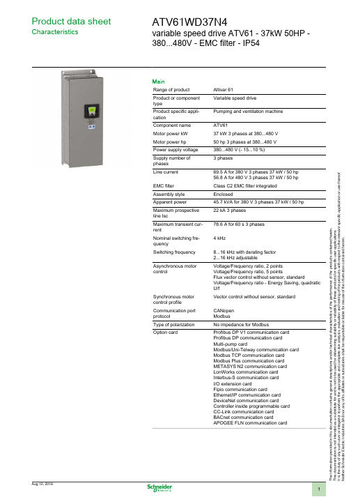
T h e i n f o r m a t i o n p r o v i d e d i n t h i s d o c u m e n t a t i o n c o n t a i n s g e n e r a l d e s c r i p t i o n s a n d /o r t e c h n i c a l c h a r a c t e r i s t i c s o f t h e p e r f o r m a n c e o f t h e p r o d u c t s c o n t a i n e d h e r e i n .T h i s d o c u m e n t a t i o n i s n o t i n t e n d e d a s a s u b s t i t u t e f o r a n d i s n o t t o b e u s e d f o r d e t e r m i n i n g s u i t a b i l i t y o r r e l i a b i l i t y o f t h e s e p r o d u c t s f o r s p e c i f i c u s e r a p p l i c a t i o n s .I t i s t h e d u t y o f a n y s u c h u s e r o r i n t e g r a t o r t o p e r f o r m t h e a p p r o p r i a t e a n d c o m p l e t e r i s k a n a l y s i s , e v a l u a t i o n a n d t e s t i n g o f t h e p r o d u c t s w i t h r e s p e c t t o t h e r e l e v a n t s p e c i f i c a p p l i c a t i o n o r u s e t h e r e o f .N e i t h e r S c h n e i d e r E l e c t r i c I n d u s t r i e s S A S n o r a n y o f i t s a f f i l i a t e s o r s u b s i d i a r i e s s h a l l b e r e s p o n s i b l e o r l i a b l e f o r m i s u s e o f t h e i n f o r m a t i o n c o n t a i n e d h e r e i n .Product data sheetCharacteristicsATV61WD37N4variable speed drive ATV61 - 37kW 50HP -380...480V - EMC filter - IP54MainRange of product Altivar 61Product or component typeVariable speed driveProduct specific appli-cationPumping and ventilation machine Component name ATV61Motor power kW 37 kW 3 phases at 380...480 V Motor power hp 50 hp 3 phases at 380...480 V Power supply voltage 380...480 V (- 15...10 %)Supply number of phases 3 phasesLine current 69.5 A for 380 V 3 phases 37 kW / 50 hp 56.8 A for 480 V 3 phases 37 kW / 50 hp EMC filter Class C2 EMC filter integrated Assembly style EnclosedApparent power 45.7 kVA for 380 V 3 phases 37 kW / 50 hp Maximum prospective line Isc22 kA 3 phases Maximum transient cur-rent78.6 A for 60 s 3 phases Nominal switching fre-quency4 kHzSwitching frequency 8...16 kHz with derating factor 2...16 kHz adjustableAsynchronous motor controlVoltage/Frequency ratio, 2 points Voltage/Frequency ratio, 5 pointsFlux vector control without sensor, standardVoltage/Frequency ratio - Energy Saving, quadratic U/fSynchronous motor control profile Vector control without sensor, standard Communication port protocolCANopen ModbusType of polarization No impedance for ModbusOption cardProfibus DP V1 communication card Profibus DP communication card Multi-pump cardModbus/Uni-Telway communication card Modbus TCP communication card Modbus Plus communication card METASYS N2 communication card LonWorks communication card Interbus-S communication card I/O extension cardFipio communication cardEthernet/IP communication card DeviceNet communication cardController inside programmable card CC-Link communication card BACnet communication cardAPOGEE FLN communication cardComplementaryProduct destination Asynchronous motorsSynchronous motorsPower supply voltage limits323...528 VPower supply frequency50...60 Hz (- 5...5 %)Power supply frequency limits47.5...63 HzContinuous output current71.5 A at 4 kHz, 380 V 3 phases65 A at 4 kHz, 460 V 3 phasesSpeed drive output frequency0.1...599 HzSpeed range 1...100 in open-loop mode, without speed feedbackSpeed accuracy+/- 10 % of nominal slip for 0.2 Tn to Tn torque variation without speed feedback Torque accuracy+/- 15 % in open-loop mode, without speed feedbackTransient overtorque130 % of nominal motor torque, +/- 10 % for 60 sBraking torque30 % without braking resistor<= 125 % with braking resistorRegulation loop Frequency PI regulatorMotor slip compensation AdjustableAutomatic whatever the loadCan be suppressedNot available in voltage/frequency ratio (2 or 5 points)Diagnostic 1 LED red presence of drive voltageOutput voltage<= power supply voltageElectrical isolation Between power and control terminalsType of cable for mounting in an enclosure Without mounting kit : 1-strand IEC cable at 45 °C, copper 90 °C XLPE/EPRWithout mounting kit : 1-strand IEC cable at 45 °C, copper 70 °C PVCWith UL Type 1 kit : 3-strand UL 508 cable at 40 °C, copper 75 °C PVCWith an IP21 or an IP31 kit : 3-strand IEC cable at 40 °C, copper 70 °C PVC Electrical connection L1/R, L2/S, L3/T, U/T1, V/T2, W/T3, PC/-, PO, PA/+, PA, PB terminal 50 mm² /AWG 1/0AI1-/AI1+, AI2, AO1, R1A, R1B, R1C, R2A, R2B, LI1...LI6, PWR terminal 2.5mm² / AWG 14Tightening torque L1/R, L2/S, L3/T, U/T1, V/T2, W/T3, PC/-, PO, PA/+, PA, PB 12 N.m / 106.2 lb.inAI1-/AI1+, AI2, AO1, R1A, R1B, R1C, R2A, R2B, LI1...LI6, PWR 0.6 N.m Supply Internal supply 24 V DC (21...27 V), <= 200 mA for overload and short-circuit pro-tectionInternal supply for reference potentiometer (1 to 10 kOhm) 10.5 V DC +/- 5 %, <=10 mA for overload and short-circuit protectionExternal supply 24 V DC (19...30 V), 30 WAnalogue input number2Analogue input type AI2 software-configurable voltage 0...10 V DC, input voltage 24 V max,impedance 30000 Ohm, resolution 11 bitsAI2 software-configurable current 0...20 mA, impedance 242 Ohm, resolution 11bitsAI1-/Al1+ bipolar differential voltage +/- 10 V DC, input voltage 24 V max, resolu-tion 11 bits + signSampling time Discrete input LI6 (if configured as logic input) 2 ms, +/- 0.5 msDiscrete input LI1...LI5 2 ms, +/- 0.5 msAnalog output AO1 2 ms, +/- 0.5 msAnalog input Al2 2 ms, +/- 0.5 msAnalog input AI1-/Al1+ 2 ms, +/- 0.5 msAbsolute accuracy precision AO1 +/- 1 % for a temperature variation 60 °CAI2 +/- 0.6 % for a temperature variation 60 °CAI1-/Al1+ +/- 0.6 % for a temperature variation 60 °CLinearity error AO1 +/- 0.2 %AI2 +/- 0.15 % of maximum valueAI1-/Al1+ +/- 0.15 % of maximum valueAnalogue output number1Analogue output type AO1 software-configurable logic output 10 V, <= 20 mAAO1 software-configurable voltage, analogue output range 0...10 V DC,impedance 470 Ohm, resolution 10 bitsAO1 software-configurable current, analogue output range 0...20 mA, impedance500 Ohm, resolution 10 bitsDiscrete output number2Discrete output type(R2A, R2B) configurable relay logic NO, electrical durability 100000 cycles(R1A, R1B, R1C) configurable relay logic NO/NC, electrical durability 100000 cy-clesMaximum response time R2A, R2B <= 7 ms, tolerance +/- 0.5 msR1A, R1B, R1C <= 7 ms, tolerance +/- 0.5 ms<= 100 ms in STO (Safe Torque Off)Minimum switching current Configurable relay logic 3 mA at 24 V DCMaximum switching current R1, R2 on resistive load, 5 A at 30 V DC, cos phi = 1, L/R = 0 msR1, R2 on resistive load, 5 A at 250 V AC, cos phi = 1, L/R = 0 msR1, R2 on inductive load, 2 A at 30 V DC, cos phi = 0.4, L/R = 7 msR1, R2 on inductive load, 2 A at 250 V AC, cos phi = 0.4, L/R = 7 ms Discrete input number7Discrete input type(PWR) safety input, 24 V DC, voltage limits <= 30 V, impedance 1500 Ohm(LI6) switch-configurable PTC probe, 0...6, impedance 1500 Ohm(LI6) switch-configurable, 24 V DC, voltage limits <= 30 V, with level 1 PLC,impedance 3500 Ohm(LI1...LI5) programmable, 24 V DC, voltage limits <= 30 V, with level 1 PLC,impedance 3500 OhmDiscrete input logic LI6 (if configured as logic input) positive logic (source), < 5 V (state 0), > 11 V(state 1)LI6 (if configured as logic input) negative logic (sink), > 16 V (state 0), < 10 V(state 1)LI1...LI5 positive logic (source), < 5 V (state 0), > 11 V (state 1)LI1...LI5 negative logic (sink), > 16 V (state 0), < 10 V (state 1) Acceleration and deceleration ramps Automatic adaptation of ramp if braking capacity exceeded, by using resistorLinear adjustable separately from 0.01 to 9000 sS, U or customizedBraking to standstill By DC injectionProtection type Motor thermal protectionMotor power removalMotor motor phase breakDrive thermal protectionDrive short-circuit between motor phasesDrive power removalDrive overvoltages on the DC busDrive overheating protectionDrive overcurrent between output phases and earthDrive line supply undervoltageDrive line supply overvoltageDrive input phase breaksDrive break on the control circuitDrive against input phase lossDrive against exceeding limit speedInsulation resistance> 1 mOhm at 500 V DC for 1 minute to earthFrequency resolution Display unit 0.1 HzAnalog input 0.024/50 HzType of connector Male SUB-D 9 on RJ45 for CANopen1 RJ45 for Modbus on terminal1 RJ45 for Modbus on front facePhysical interface2-wire RS 485 for ModbusTransmission frame RTU for ModbusTransmission rate20 kbps, 50 kbps, 125 kbps, 250 kbps, 500 kbps, 1 Mbps for CANopen9600 bps, 19200 bps for Modbus on front face4800 bps, 9600 bps, 19200 bps, 38.4 Kbps for Modbus on terminalData format8 bits, odd even or no configurable parity for Modbus on terminal8 bits, 1 stop, even parity for Modbus on front faceNumber of addresses 1...247 for Modbus1...127 for CANopenMethod of access Slave for CANopenMarking CEOperating position Vertical +/- 10 degreeProduct weight64 kgWidth285 mmHeight880 mmDepth343 mmEnvironmentNoise level64 dB conforming to 86/188/EECDielectric strength5092 V DC between control and power terminals3535 V DC between earth and power terminalsElectromagnetic compatibility Voltage dips and interruptions immunity test conforming to IEC 61000-4-11Radiated radio-frequency electromagnetic field immunity test conforming to IEC61000-4-3 level 3Electrostatic discharge immunity test conforming to IEC 61000-4-2 level 3Electrical fast transient/burst immunity test conforming to IEC 61000-4-4 level 4Conducted radio-frequency immunity test conforming to IEC 61000-4-6 level 3 Standards EN 55011 class A group 1EN 61800-3 environments 1 category C2EN 61800-3 environments 2 category C2EN/IEC 61800-3EN/IEC 61800-5-1IEC 60721-3-3 class 3C1IEC 60721-3-3 class 3S2UL Type 12Product certifications CSAC-TickDNVGOSTNOM 117ULPollution degree 3 conforming to UL 8403 conforming to EN/IEC 61800-5-1Degree of proctection IP54 conforming to UL Type 12IP54 conforming to EN/IEC 61800-5-1IP54 conforming to EN/IEC 60529Vibration resistance 1.5 mm peak to peak (f = 3...13 Hz) conforming to EN/IEC 60068-2-61 gn (f = 13...200 Hz) conforming to EN/IEC 60068-2-6Shock resistance15 gn for 11 ms conforming to EN/IEC 60068-2-27Relative humidity 5...95 % without dripping water conforming to IEC 60068-2-35...95 % without condensation conforming to IEC 60068-2-3Ambient air temperature for operation-10...50 °C with derating factor-10...40 °C without deratingAmbient air temperature for storage-25...70 °COperating altitude1000...3000 m with current derating 1 % per 100 m<= 1000 m without deratingDimensions DrawingsUL Type 12/IP 54 Drives DimensionsDimensions in mmDimensions in in.Mounting and ClearanceMounting RecommendationsDepending on the conditions in which the drive is to be used, its installation will require certain precautions and the use of appropriate accessories.Install the unit vertically:●Avoid placing it close to heating elements●Leave sufficient free space to ensure that the air required for cooling purposes can circulate from the bottom to the top of the unit. ClearanceMountingConnections and SchemaWiring Diagram Conforming to Standards EN 954-1 Category 1, IEC/EN 61508 Capacity SIL1, in Stopping Category 0 According to IEC/EN 60204-1Three-Phase Power Supply with Upstream Breaking via ContactorA1ATV61 driveKM1ContactorL1DC chokeQ1Circuit-breakerQ2GV2 L rated at twice the nominal primary current of T1Q3GB2CB05S1,XB4 B or XB5 A pushbuttonsS2T1100 VA transformer 220 V secondary(1)Line choke (three-phase); mandatory for ATV61HC11Y…HC80Y drives (except when a special transformer is used (12-pulse)).(2)For ATV61HC50N4, ATV61HC63N4 and ATV61HC50Y…HC80Y drives, refer to the power terminal connections diagram.(3)Fault relay contacts. Used for remote signalling of the drive status.(4)Connection of the common for the logic inputs depends on the positioning of the SW1 switch. The above diagram shows the internalpower supply switched to the “source” position (for other connection types, refer to the user guide).(5)There is no PO terminal on ATV61HC11Y…HC80Y drives.(6)Optional DC choke for ATV61H•••M3, ATV61HD11M3X…HD45M3X and ATV61H075N4…HD75N4 drives. Connected in place of thestrap between the PO and PA/+ terminals. For ATV61HD55M3X…HD90M3X, ATV61HD90N4…HC63N4 drives, the choke is supplied with the drive; the customer is responsible for connecting it. For ATV61W•••N4 and ATV61W•••N4C drives, the DC choke is integrated.(7)Software-configurable current (0…20 mA) or voltage (0…10 V) analog input.(8)Reference potentiometer.NOTE: All terminals are located at the bottom of the drive. Fit interference suppressors on all inductive circuits near the drive or connected on the same circuit, such as relays, contactors, solenoid valves, fluorescent lighting, etc.Wiring Diagram Conforming to Standards EN 954-1 Category 1, IEC/EN 61508 Capacity SIL1, in Stopping Category 0 According to IEC/EN 60204-1Three-Phase Power Supply with Downstream Breaking via Switch DisconnectorA1ATV61 driveL1DC chokeQ1Circuit-breakerQ2Switch disconnector (Vario)(1)Line choke (three-phase), mandatory for ATV61HC11Y…HC80Y drives (except when a special transformer is used (12-pulse)).(2)For ATV61HC50N4, ATV61HC63N4 and ATV61HC50Y…HC80Y drives, refer to the power terminal connections diagram.(3)Fault relay contacts. Used for remote signalling of the drive status.(4)Connection of the common for the logic inputs depends on the positioning of the SW1 switch. The above diagram shows the internalpower supply switched to the “source” position (for other connection types, refer to the user guide).(5)There is no PO terminal on ATV61HC11Y…HC80Y drives.(6)Optional DC choke for ATV61H•••M3, ATV61HD11M3X…HD45M3X and ATV61H075N4…HD75N4 drives. Connected in place of thestrap between the PO and PA/+ terminals. For ATV61HD55M3X…HD90M3X, ATV61HD90N4…HC63N4 drives, the choke is supplied with the drive; the customer is responsible for connecting it. For ATV61W•••N4 and ATV61W•••N4C drives, the DC choke is integrated.(7)Software-configurable current (0…20 mA) or voltage (0…10 V) analog input.(8)Reference potentiometer.NOTE: All terminals are located at the bottom of the drive. Fit interference suppressors on all inductive circuits near the drive or connected on the same circuit, such as relays, contactors, solenoid valves, fluorescent lighting, etc.Wiring Diagram Conforming to Standards EN 954-1 Category 3, IEC/EN 61508 Capacity SIL2, in Stopping Category 0 According to IEC/EN 60204-1Three-Phase Power Supply, Low Inertia Machine, Vertical MovementA1ATV61 driveA2Preventa XPS AC safety module for monitoring emergency stops and switches. One safety module can manage the “Power Removal”function for several drives on the same machine. In this case, each drive must connect its PWR terminal to its + 24 V via the safety contacts on the XPS AC module. These contacts are independent for each drive.F1FuseL1DC chokeQ1Circuit-breakerS1Emergency stop button with 2 contactsS2XB4 B or XB5 A pushbutton(1)Power supply: 24 Vdc or Vac, 115 Vac, 230 Vac.(2)S2: resets XPS AC module on power-up or after an emergency stop. ESC can be used to set external starting conditions.(3)Requests freewheel stopping of the movement and activates the “Power Removal” safety function.(4)Line choke (three-phase), mandatory for and ATV61HC11Y…HC80Y drives (except when a special transformer is used (12-pulse)).(5)The logic output can be used to signal that the machine is in a safe stop state.(6)For ATV61HC50N4, ATV61HC63N4 and ATV61HC50Y…HC80Y drives, refer to the power terminal connections diagram.(7)Fault relay contacts. Used for remote signalling of the drive status.(8)Connection of the common for the logic inputs depends on the positioning of the SW1 switch. The above diagram shows the internalpower supply switched to the “source” position (for other connection types, refer to the user guide).(9)Standardized coaxial cable, type RG174/U according to MIL-C17 or KX3B according to NF C 93-550, external diameter2.54 mm /0.09 in., maximum length 15 m / 49.21 ft. The cable shielding must be earthed.(10)There is no PO terminal on ATV61HC11Y…HC80Y drives.(11)Optional DC choke for ATV61H•••M3, ATV61HD11M3X…HD45M3X and ATV61H075N4…HD75N4 drives. Connected in place of thestrap between the PO and PA/+ terminals. For ATV61HD55M3X…HD90M3X, ATV61HD90N4…HC63N4 drives, the choke is supplied with the drive; the customer is responsible for connecting it. For ATV61W•••N4 and ATV61W•••N4C drives, the DC choke is integrated.(12)Software-configurable current (0…20 mA) or voltage (0…10 V) analog input.(13)Reference potentiometer.NOTE: All terminals are located at the bottom of the drive. Fit interference suppressors on all inductive circuits near the drive or connected on the same circuit, such as relays, contactors, solenoid valves, fluorescent lighting, etc.Wiring Diagram Conforming to Standards EN 954-1 Category 3, IEC/EN 61508 Capacity SIL2, in Stopping Category 1 According to IEC/EN 60204-1Three-Phase Power Supply, High Inertia MachineA1ATV61 driveA2 (5)Preventa XPS ATE safety module for monitoring emergency stops and switches. One safety module can manage the "Power Removal”safety function for several drives on the same machine. In this case the time delay must be adjusted on the drive controlling the motor that requires the longest stopping time. In addition, each drive must connect its PWR terminal to its + 24 V via the safety contacts on the XPS ATE module. These contacts are independent for each drive.F1FuseL1DC chokeQ1Circuit-breakerS1Emergency stop button with 2 contactsS2XB4 B or XB5 A pushbutton(1)Power supply: 24 Vdc or Vac, 115 Vac, 230 Vac.(2)Requests controlled stopping of the movement and activates the “Power Removal” safety function.(3)Line choke (three-phase), mandatory for ATV61HC11Y…HC80Y drives (except when a special transformer is used (12-pulse)).(4)S2: resets XPS ATE module on power-up or after an emergency stop. ESC can be used to set external starting conditions.(5)The logic output can be used to signal that the machine is in a safe state.(6)For stopping times requiring more than 30 seconds in category 1, use a Preventa XPS AV safety module which can provide amaximum time delay of 300 seconds.(7)For ATV61HC50N4, ATV61HC63N4 and ATV61HC50Y…HC80Y drives, refer to the power terminal connections diagram.(8)Fault relay contacts. Used for remote signalling of the drive status.(9)Connection of the common for the logic inputs depends on the positioning of the SW1 switch. The above diagram shows the internalpower supply switched to the “source” position (for other connection types, refer to the user guide).(10)Standardized coaxial cable, type RG174/U according to MIL-C17 or KX3B according to NF C 93-550, external diameter2.54 mm/0.09 in., maximum length 15 m/49.21 ft. The cable shielding must be earthed.(11)Logic inputs LI1 and LI2 must be assigned to the direction of rotation: LI1 in the forward direction and LI2 in the reverse direction.(12)There is no PO terminal on ATV61HC11Y…HC80Y drives.(13)Optional DC choke for ATV61H•••M3, ATV61HD11M3X…HD45M3X and ATV61H075N4…HD75N4 drives. Connected in place of thestrap between the PO and PA/+ terminals. For ATV61HD55M3X…HD90M3X, ATV61HD90N4…HC63N4 drives, the choke is supplied with the drive; the customer is responsible for connecting it. For ATV61W•••N4 and ATV61W•••N4C drives, the DC choke is integrated.(14)Software-configurable current (0…20 mA) or voltage (0…10 V) analog input.(15)Reference potentiometer.NOTE: All terminals are located at the bottom of the drive. Fit interference suppressors on all inductive circuits near the drive or connected on the same circuit, such as relays, contactors, solenoid valves, fluorescent lighting, etc.Product data sheet Performance Curves ATV61WD37N4Derating CurvesThe derating curves for the drive nominal current (In) depend on the temperature and the switching frequency. For intermediate temperatures(e.g. 55°C), interpolate between 2 curves.X Switching frequency。
信捷DP-508、DP-508-L步进驱动器用户手册20130420

无锡信捷电气股份有限公司资料编号DC04 20120924 1.0DP-508/DP-508-L细分驱动器用户手册1、产品概述 (1)1-1.性能特点 (1)1-2. 应用领域 (1)1-3. 电气特性 (1)2、使用指导 (2)2-1. 安全事项 (2)2-2. 连线注意点 (2)2-3. 安装环境 (2)3、接口和功能介绍 (3)3-1. 控制信号接口 (3)3-1-1. 控制信号接口功能描述 (3)3-1-2. 控制信号时序图 (3)3-1-3. 输入电路及相关要求 (4)3-2.功率接口 (4)3-2-1. 强电接口功能描述 (4)3-2-2. 供电电源要求 (5)3-2-3. 与电机接线 (5)3-3. 功能设定 (5)3-3-1. 电流设定 (6)3-3-2. 每转脉冲数设定 (6)3-4. 保护功能 (6)4、尺寸、安装及典型接线 (8)4-1.尺寸 (8)4-2.安装 (8)4-3.典型接线 (8)5、故障诊断和排除 (9)6、电机选配 (10)iDP-508/DP-508-L细分驱动器用户手册iiDP-508/DP-508-L细分驱动器用户手册细分型步进驱动器DP-508/DP-508-L最大输入电压80VDC。
输出电流5.0A,可驱动5.0A 以下各种二相混合式步进电机,该产品采用纯正弦波电流控制技术,使电机运行平稳,噪声小,特别适用于激光打标机、数控机床等分辨率较高的小型数控设备上。
1-1.性能特点⏹超低电机运行噪声⏹供电电压可达80VDC,建议不低于48VDC⏹输出电流有效值可达5.0A⏹细分动态可选,每转脉冲数最大可达40000⏹可驱动任何5.0A以下4,6,8线两相步进电机⏹光隔离信号输入⏹电流设定方便,任意档可选⏹具有过压、过流保护功能1-2. 应用领域适用于各种中小型和自动化设备及仪器,如:气动打标机、贴标机、割字机、激光打标机、绘图仪、小型雕刻机、数控机床、拿放装置等。
UPG 508 网络分析仪用户手册说明书
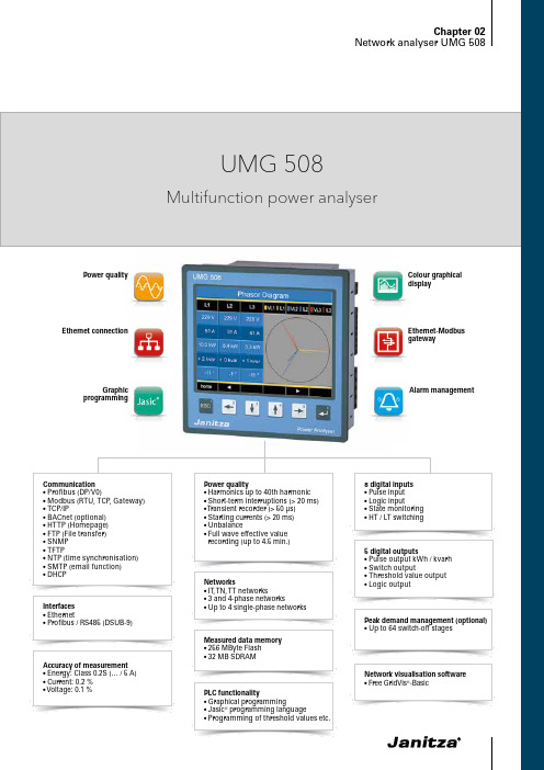
Alarm managementColour graphical displayPower qualityGraphic programmingEthernet connection5 digital outputs•Pulse output kWh / kvarh •Switch output•Threshold value output •Logic output•Pulse input •Logic input•State monitoring •HT / LT switchingPeak demand management (optional)•Up to 64 switch-off stagesNetwork visualisation software • Free GridVis ®-BasicInterfaces •Ethernet•Profibus / RS485 (DSUB-9)• T FTP•N TP (time synchronisation)•S MTP (email function)• D HCP•Energy: Class 0.2S (… / 5 A)•Current: 0.2 %• Voltage: 0.1 %Networks• IT , T N, T T networks•3 and 4-phase networks•Up to 4 single-phase networksMeasured data memory • 256 MByte Flash • 32 MB SDRAM•Unbalance•F ull wave effective value recording (up to 4.5 min.)PLC functionality•Graphical programming•Jasic ® programming language•Programming of threshold values etc.Ethernet-Modbus gatewayChapter 02UMG 508•Continuous monitoring of the power quality •Energy management systems (ISO 50001)• M aster device with Ethernet gateway for subordinate measurement points• Visualisation of the energy supply in the L VDB • A nalysis of electrical disturbances in the event of power quality problems •Cost centre analysis•Remote monitoring in the property operation •Use in test fields (e.g. in universities)Areas of applicationMain featuresHigh quality measurement with high sampling rate (20 kHz per channel)Power quality•Harmonics analysis up to 40th harmonic • Acquisition of short-term interruptions • Acquisition of transients•Display of waveforms (current and voltage)•Unbalance• Vector diagramUser -friendly, colour graphical display with intuitive user guidance •High resolution graphics display•User-friendly, self-explanatory and intuitive operation • C lear and informative representation of online graphs and further power quality eventsModern communications architecture via Ethernet•Ethernet interface and web server • F aster, better cost-optimised and more reliable communication system•High flexibility due to the use of open standards • I ntegration in PLC systems and BMS through additional interfaces • BACnet optionally availableFig.: GridVis ® – Graph setFig.: Large colour display, e.g. 12 monthly demandvaluesFig.: Illustration of the full wave effective valuesfor an eventChapter 02UMG 508Modbus Gateway function• E conomical connection of devices without Ethernet interface • I ntegration of devices with Modbus-RTU interface possible •Data can be scaled and described•Minimised number of IP addresses requiredGraphical programming•Comprehensive programming options (PLC functionality)•Jasic ® source code programming • S ustainable functional expansions far beyond pure measurement•Complete APPs from the Janitza libraryPowerful alarm management• C an be programmed via the graphic programming or Jasic ®source code• All measured values can be used•Can be arbitrarily, mathematically processed• Individual forwarding via email sending, switching of digital outputs, writing to Modbus addresses etc.• Watchdog APP• Further alarm management functions via GridVis ®-Service alarmmanagementFig.: GridVis ® topology viewFig.: The alarm management system reports events arising in good time.Fig.: Example for the configuration of currentmeasurement via 3 current transformers in a three-phase 4-wire network on the UMG 508 displayChapter 02UMG 508Typical connectionSide viewView from belowDimension diagramsAll dimensions in mmCut out: 138+0,8 x 138+0,8 mmChapter 02UMG 508Device overview and technical dataChapter 02UMG 5081 ) T he device can only determine measured values, if an L -N voltage of greater than 10 Veff or an L -L voltage of greater than 18 Veff is applied to atleast one voltage measurement input.Chapter 02UMG 508Fig.: Current and voltage measurementFig.: Connection of two electronic relays to digitaloutputs 4 and 5Comment: For detailed technical information please refer to the operation manual and the Modbus address list.。
得力DL-220D微型针式打印机用户手册 说明书

DL-220D/DL-220B用户手册V1.0安全指引请在使用本产品前仔细阅读本手册,不要执行本手册中没有明确说明的操作。
未经授权的操作会导致错误或意外。
制造商对因错误操作而导致打印机出现的任何问题均不负责。
为了避免受到电击和伤害及防止损坏打印机,在接上电源之前,务请注意以下重要事项:●仔细阅读操作手册等说明文件。
●打印机必须平放在固定的台面上。
●避免震动、碰撞、高温和阳光直射、灰尘等。
●请勿将打印机置于潮湿的环境中,请勿让雨水等任何液体沾湿打印机。
●打印机应安放在接近插座的地方,方便操作者进行电源插头的拔插操作。
●确保电源的电压值与打印机所规定的电压值一致,避免与电冰箱等大功率或有干扰的电器同一电源。
●为保证安全操作,三脚插头必须插进三孔交流电源插座中,其中地线必须有效接地。
●电源延长线必须为三芯并正确连接,以提供接地。
●若交流电源插座与打印机插头不匹配,请更换合适的交流电源插座,以保证人员、设备的安全使用。
●连接打印机通讯电缆时,请先关闭打印机和计算机的电源,选用适合的联机电缆将打印机和计算机连接起来,并锁定卡口和旋紧螺丝。
●请勿接触打印头外壳,以防止高温伤害。
●清洁打印机前,先关闭电源开关,从电源插座拔掉电源插头。
用软棉绒布沾少量中性清洁剂或酒精,轻抺打印机外部。
●如遇打印机发生故障,除认可的合格技术员外,不可擅自进行维修工作。
注:本手册内容如有更改,恕不另行通知。
目录第一章安装打印机 (4)1.1 开箱和检查 (4)1.2 放置打印机 (5)1.3 打印机部件 (6)1.4 打印机与主机连接 (7)1.5 连接电源 (8)1.6 安装纸卷 (9)1.7 安装色带 (10)1.8 安装驱动程序 (10)第二章控制面板操作 (14)2.1 指示灯 (14)2.2 走纸键 (14)第三章参数设置 (15)3.1如何进行参数设置 (15)3.2自检打印 (16)3.3系统设置 (17)3.4接口设置 (17)3.5纵向校正 (18)3.6十六进制 (18)3.7恢复出厂设置 (19)3.8安装智能助手工具 (20)第四章功能设置 (23)4.1 黑标设置 (23)4.1.1 黑标规格 (23)4.1.2 运行设置工具 (23)4.1.3 设置打印起始位置 (24)4.1.4 设置切纸位置 (25)4.1.4 设置黑标间距 (26)4.2 驱动属性设置 (26)4.2.2 钱箱设置 (26)4.2.3 黑标设置 (27)4.2.4 切刀设置 (27)第五章程序更新 (28)5.1 程序更新 (28)第六章故障处理 (30)6.1 指示灯与蜂鸣器 (30)6.2 打印错误 (30)6.3 卡纸处理 (31)6.4 清洁保养 (31)第七章规格参数与性能指标 (32)7.1 打印机规格 (32)7.2 通讯接口引脚 (33)7.2.1 USB接口 (33)7.2.2 钱箱接口 (33)7.2.3 串行接口 (34)7.2.4 并行接口 (34)7.3 电源适配器 (36)7.4 纸张规格 (37)第八章字符集 (38)8.1 通用代码页 (国际字符集: USA) (38)8.2 [PC437: USA, 欧洲标准] (39)8.3 [PC850: 多国文字] (40)8.4 [PC860: 葡萄牙文] (41)8.5 [PC863: 加拿大文-法文] (42)8.6 [PC865: 北欧文] (43)8.7 [PC858: 欧文] (44)8.8 [PC866: 古斯拉夫文 #2] (45)8.9 [KU42: 泰文] (46)8.10 [PC862: 希伯来文] (47)8.11 [PC737: 希腊文] (48)8.12 [PC864: 阿拉伯文] (49)8.13 [PC857: 土耳其文] (50)第九章指令集 (51)9.1 字符控制命令 (52)9.2 打印控制命令 (55)9.3 点图命令 (58)9.4 汉字命令 (59)9.5 黑标及切刀控制命令 (61)9.6 其他命令 (63)附录:电子信息产品污染控制的说明 (65)第一章 安装打印机1.1 开箱和检查打开纸箱,取出打印机并拆除保护材料。
欧瑞传动sd20伺服驱动器安装、调试、使用手册说明书
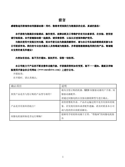
前言感谢您选用欧瑞传动伺服驱动器!同时,您将享受到我们为您提供的全面、真诚的服务!本手册将为您提供安装调试、操作使用、故障诊断及日常维护的有关注意事项,在安装、使用前请仔细阅读。
本手册随驱动器一起提供,请妥善保管,以备以后查阅和维护使用。
当您在使用中发现任何问题,而本手册无法为您提供解答时,请与本公司各地经销商或直接与本公司联系咨询。
我们的专业技术服务人员将竭诚为您服务,并希望您能继续选用我们的产品,敬请提出宝贵的意见和建议!内容如有改动,恕不另行通知。
版权所有,保留一切权利。
本公司致力于产品的不断改善和功能升级,手册提供资料如有变更,恕不一一通知。
最新及详细版使用手册会在公司网站()上进行公布。
开箱验货:在开箱时,请认真确认:■ 安全标识本产品的安全运行取决于正确的安装和操作以及运输与保养维护,请务必遵守本手册中使用的如下安全标识:错误的操作将引发危险情况,导致人身伤亡。
错误的操作将引发危险情况,导致轻度或中度人身伤害,损坏设备。
另外,该标识中所述事项有时也可能造成严重的后果。
驱动器外壳上标识符的意义如下:电压高,有电击危险。
表面热,禁止触摸。
■ IEC 标准本产品严格按照最新国际标准进行测试生产:IEC/EN 61800-5-1:2007—可调速电气传动系统安全要求IEC/EN 61800-3:2004/+A1:2012—可调速电气传动系统,第三部分:产品的电磁兼容性标准及其特定的试验方法敬请注意:请正确连接电子变压器线序,否则会导致危险!电子变压器通用接线方式注意危险危险本手册使用须知:■ 基本用语除特殊说明,本手册中使用如下专有名词:伺服驱动器:用来驱动和控制伺服电机。
伺服系统:伺服驱动器、伺服电机、指令控制器以及外围装置构成的伺服控制系统。
用户参数:用于监控或设定驱动器相关参数,分为监控参数和设定参数。
监控参数只能查看不能修改;设定参数可以查看和修改,并可根据作用分为功能参数和数据参数。
施耐德万高D型控制器使用说明

高字节未用
3
--
44
2C
1
故障标志2
BIT7 --空
BIT6 --空
BIT5 --空
BIT4=1 --备用合闸
BIT3=1 --常用合闸
BIT2=1 --故障锁定
BIT1=1 --备用脱扣
BIT0=1 --常用脱扣
3
常用和备用脱扣仅应用于CB级产品
45
2D
1
转换次数
3
次
46
消防联动(无源):短接此两点,机构转到双分位置,开关状态主分备分;(可靠距离10m,WTS-D800~5000系列不具备该项功能)
: 控制器的发电机启动端子在常用电源正常时常闭触点断开,当常用电源故障时常闭触点闭合以接通发电机启动电路;常开触点与之相反,请用户注意。
: 两台断路器的主回路相序必须一致。
附录1 通讯协议
D型控制器配有RS485通讯接口,可与SCADA系统、DCS系统或具有ModBus兼容的监控系统之间进行信息和数据的有效传送。通过监控系统实现对自动转换开关的“四遥”操作,
一、工作参数
通讯接口
RS-485
螺丝式固定端子,便于接线
EIA标准2线微分通讯
控制器出厂默认设置
波特率:9600,1位起始位,8位数据位,2位停止位,无校验
功能码:功能码为每次通讯传送的信息帧的第二个数据帧,告诉子机执行相应功能。本模块利用了两个指令从主机获取要执行的任务及提供的服务。
功能码
定义
03H
读数据
06H
写单个寄存器(遥控)
数据区:数据区是根据不同的功能码而不同。数据区可以是实际数值、设置点、主机发送给从机或从机发送给主机的地址。不同的数据区存储了控制器的不同工作状态及工作参数。如附录地址列表所示。
海康威视 'D5PF' 插座式驱动器系列说明书
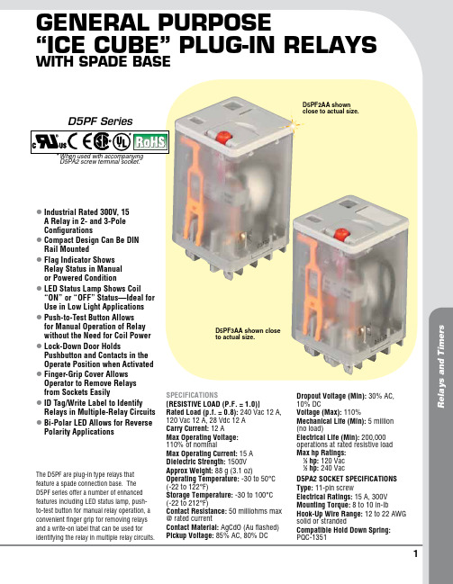
1R e l a y s a n d T i m e r sGeneral PurPose“Ice cube” PluG-In relayswIth sPade baselI ndustrial Rated 300V, 15 A Relay in 2- and 3-Pole Configurations lC ompact Design Can Be DIN Rail Mounted lF lag Indicator Shows Relay Status in Manual or Powered Condition lL ED Status Lamp Shows Coil “ON” or “OFF” Status—Ideal for Use in Low Light Applications lP ush-to-Test Button Allows for Manual Operation of Relay without the Need for Coil Power lL ock-Down Door Holds Pushbutton and Contacts in the Operate Position when Activated lF inger-Grip Cover Allows Operator to Remove Relays from Sockets Easily lI D Tag/Write Label to Identify Relays in Multiple-Relay Circuits lB i-Polar LED Allows for Reverse Polarity ApplicationsThe D5PF are plug-in type relays that feature a spade connection base. The D5PF series offer a number of enhanced features including LED status lamp, push-to-test button for manual relay operation, a convenient finger grip for removing relays and a write-on label that can be used for identifying the relay in multiple relay circuits.SPECIFICATIONS[RESISTIVE LOAD (P.F. = 1.0)]Rated Load (p.f. = 0.8): 240 Vac 12 A, 120 Vac 12 A, 28 Vdc 12 A Carry Current: 12 AMax Operating Voltage: 110% of nominalMax Operating Current: 15 A Dielectric Strength: 1500V Approx Weight: 88 g (3.1 oz)Operating Temperature: -30 to 50°C (-22 to 122°F)Storage Temperature: -30 to 100°C (-22 to 212°F)Contact Resistance: 50 milliohms max @ rated currentContact Material: AgCdO (Au flashed) Pickup Voltage: 85% AC, 80% DCDropout Voltage (Min): 30% AC, 10% DCVoltage (Max): 110%Mechanical Life (Min): 5 million (no load)Electrical Life (Min): 200,000 operations at rated resistive load Max hp Ratings: 1⁄3 hp: 120 Vac 1⁄2 hp: 240 VacD5PA2 SOCkET SPECIFICATIONS Type: 11-pin screwElectrical Ratings: 15 A, 300V Mounting Torque: 8 to 10 in-lbHook-Up Wire Range: 12 to 22 AWG solid or strandedCompatible Hold Down Spring: PQC-1351D5PF2AA shown close to actual size.D5PF3AA shown close to actual size.D5PF Series* W hen used with accompanying D5PA2 screw terminal socket.*2Three D5PF3AA, 3 PDT 11-pin relays for 120 Vac, three D5PF2-BC, DIN rail sockets with hold down spring.35.5(1.40)Tolerances: ±0.25 (±0.010) Unless Otherwise ShownD5PA2, socket, shown smaller than actual size.。
信捷产品使用知识

以DP-7022为例:
DP-系列号
70-最大输出电流(30-3.0A,50-5.0A,70-7.0A)
21-供电电压(21-220V,2-40V,8-80V)
伺服(Servo)一语源出于拉丁语的Servus(英语为Slave:奴隶)。奴隶的功用是忠实地遵从主人的命令从事劳力工作。也就是“依指令确实执行动作驱动装置;具有高精度的灵敏动作的表现,自我动作状态常时确认”。而具有这种功能的装置就称为“伺服”。
T-BOX优点:
1、支持多主多从
2、可远程上下载程序和数据监控,速度快。
3、支持多家组态,开放性更好。如:组态王和力控软件,除了它们支持modbusTCP协议的都可以.
4、传输速度快,传送数据量大。
与T-BOX的命名方式相同,由于G-BOX(无线数据传输模块)是利用GPRS进行通讯的,故称G-BOX,是MODBUS与GPRS技术的完美结合,支持232/485接口。
信捷一体机包括XP系列,XMP系列以及XMH系列。
命名规则:
以XP3-16RT-E clock为例:
XP----系列名称(XP表示是PLC与文本的结合,XMP表示PLC与MP的结合,XMH表示PLC与TH触摸屏的结合)。
3----XC系列PLC型号(1表示PLC是XC1,2表示PLC是XC2,3表示PLC是XC3)。
命名规则
A、本体:
XC系列PLC本体型号说明以XC3-32PRT-E(报价单上只罗列了NPN型,每一款都有对应的PNP型)为例:
XC3——系列号,32——I/O点数,P——输入类型(P表示PNP输入/没有P的表示NPN型输入)RT——输出类型(R表示继电器/T表示晶体管)。
E——表示供电电源(E表示220v交流供电/C表示24v直流供电)
FURUNO NBDP TERMINAL DP-6 安装说明书
RINSTALLATION MANUAL NBDP TERMINAL DP-6SAFETY INSTRUCTIONS (i)1. System Configuration (1)2. Equipment Lists (2)3. Mounting (7)4. Wiring (9)5. Initial Settings (10)Outline Drawing....................................................D-1 Interconnection Diagram.....................................S-1 Schematic Diagram..............................................S-2NISHINOMIYA, JAPAND : M A Y 31, 19999-52, A s h i h a r a -c h o ,N i s h i n o m i y a , J a p a n T e l e p h o n e : 0798-65-2111T e l e f a x : 0798-65-4200A l l r i g h t s r e s e r v e d.Printed in JapanP U B. N o. I M E -56100-DD P -6(T E N I )c"WARNING" and "CAUTION" notices appear throughout this manual. It is the responsibil-ity of the installer of the equipment to read, understand and follow these notices. If you have any questions regarding these safety instructions, please contact a FURUNO agent or dealer.The level of risk appearing in the notices is defined as follows:iii1. System Configuration12. Equipment ListsStandard SetemaN e p yT y t Q)g k(s s aM s k r ameR1t i nUn i aM6-PD15.42t i nUl a n i mr e T185-B I10.6s l a i r e t am.t s n I/we e S(05110-61PC4e g a p a).3n o i t a l l a t s n Is l a i r e t aM00470-50PC1.3e g a pe e SOptional EquipmentemaN e p yT)g k(s s aM s k r ameR1r e t n i r P015-PP6.3n o i t a l l a t s n I/we g a pe e S(s l a i r e t amb4s e i r o s s e c cAd n a).e e S(00100-61PFe g a p5).2r e i f i t c eR26-RP0.3s n i amCAr o F234564b3. MountingMounting GuidelinesThe main unit and terminal unit are designed for tabletop mounting.They may be installed almost anywhere provided the location satis-fies the following conditions:¡The ambient temperature range is -15 to +55;.¡For the terminal unit, select a place where the keyboard can beeasily operated while viewing the display screen.¡Locate the units a sufficient distance from air conditioners, heatsources and ventilation fans.¡Water splash will most assuredly harm the sensitive componentsinside the units. Keep the units away from areas subject to watersplash or water spray.¡Select a place where vibration is minimal.¡Leave enough space around the sides and rear of the units to per-mit checking and maintenance and to allow for circulation of cool-ing air.¡Keep the units out of direct sunlight.¡Keep the units away from magnetic fields (telephone, refrigerator,compass, etc.)Main UnitFix the unit with four tapping screws, referring to the outline drawingon page D-1.Leave at least 100 mm at the sides and at least 150 mm at the rear topermit easy checking and maintenance.Terminal Unit1. Fix the hanger to the table with four tapping screws, referring to outline drawing on page D-2.2. Attach connectors to bottom panel. (See next page)3. Set the terminal unit to the hanger with two knobs.4. Adjust the display screen so it can be easily viewed and tighten knobs.Leave at least 80 mm at the sides and rear to permit the checking and maintenance.Keyboard1. Attach the four “hook loop fasteners 3” (small ones) to the bottom of the keyboard.2. Attach the four “hook loop fasteners 4” (large ones) to the “hook loop fasteners 3” attached to the keyboard bottom.3. Remove seals from the “hook loop fasteners 4”.4. Set the keyboard on the mounting location and press down firmly.PrinterFix the printer to mounting location with two printer fixtures (sup-plied).380204-φ 6.5Fixing holesMounting Fixture(2)CP16-00502(96)37628020042.5405425Mounting Fixture(1)CP16-005014. WiringSSB Radiotelephone DSC TerminalNavigation device *1*1Main UnitCopper strapfor grounging24VDC*2*1 : Attach connectors in field.*2 : Attach connectors before fixing the terminal unit to the hanger.5. Initial SettingAnswerback Code & ID CodeEnter vessel’s answerback code and ID code as follows.Answerback CodeProcedure1. Press function key F5 and then the [5] key. The display shouldlook something like below.Answerback Code Entry Screen2. Enter vessel’s answerback code (max. 20 characters, includingspaces). Press the ENTER key. The prompt OK/CANCEL asksfor verification of data. If correct, press the ENTER key again.ExampleMessage for confirmation of code entered3. For final verification of the data, the above CAUTION appears. If correct, press the ENTER key again.NOTE: Form of answerback depends on coast statiton. Some re-quest ship name and/or callsingn.ID CodeProcedure1. Press function key F5 and then the [6], [7], [8] or [9] key to enter the Group ID Code (4 or 5 digits), Group ID Code (9 digits), Se-lect ID Code (4/5 digits) or Select ID Code (9 digits), respectively.ID Code Screen2. Enter group ID or select ID. Then, press the ENTER key. A prompt asks for verification of data. If correct, press the ENTER key. ExampleMessage for confirmation of code entered3. For final verification of the data, the above CAUTION appears. If correct, press the ENTER key again.Note: Application software of DP-6 is already installed in the unit. The floppy disk programed in the accessores is for backup.System SettingsPress function key F6 to display the System screen.ProcedureTo change settings, press the [] key to display change (on the Setup line) in inverse video. Press the [] key to select item, then press the[] or [] key to select option.(“Default” on the Setup line is for factory use.)Menu DescriptionSetupLock/unlocks settings.Slave DelaySets the length of the slave delay timing in the ARQ mode, between 0 - 50 msec.BK Timing Pre ToneSets the timing for the leading edge of the BK signal in the ARQ mode. Post Tone Sets the timing for the trailing edge of theBK signal.Mute Timing Pre BK Sets the timing for the leading edge of themute signal in the ARQ mode.Post BK Sets the timing for the trailing edge of themute signal.NOTE: For further details about BK timing and mute timing, see page 14.Modem Output Level Adjusts output signal from the modem, be-tween -30 and +10 dBm. Refer to operation’smanual of radiotelephone connected. WithFURUNO radiotelephone, the default set-ting is available.MIF CommandTune*With FURUNO transmitter connected, ONsends antenna coupler tuning command. Freeze*With FURUNO radio equipment connected,ON sends “freeze” command to disable con-trols of radio equipment.AGC*Turn on for radio equipment which supportsAGC command in the MIF format, so thatthe gain is automatically controlled in thetelex mode.Emission*ON sends EM (emission) command to ra-diotelephone.TX/RX MSG Save An outgoing or incoming message can besaved automatically to a floppy disk.Edit before Sending OFF: Transmits keying operation one byone.ON:Transmits message only when theENTER key is pressed.*: These commands are available according to a model connected.INFORMATION RECEIVING STATION TMINGRX MUTE Signal to Transceiver TX KEY Signal to Transceiver Signal SequenceMUTE ONBK OFFBK OFF MUTE OFF BK ONMUTE OFF 5:SLAVE DELAY 3:BK TIMING PRE TONE 4:BK TIMING POST TONE 1:MUTE TIMING PRE BK 2:MUTE TIMING POST BKTiming values depend on the transceiver connected. Therefore some trial and error may be necessary to find suitable values.Default values are for FURUNO SSB Radiotelephone model FS-1500or FS-1562.Setting of TimingTiming (msec)FS-5000 series FS-8000 series FS-1562FS-1500 series FS-1502FS-1552RC-258RC-508RC-808RC-1208Slave DelayBK Timing PretonePost ToneMUTE Timing Pre BKPost BK5 msec 10 msec 0 msec 0 msec 0 msec 5050100055000DP-6MIF AGCSystem settingof eachequipment RemarksON (FS-1562 : OFF)9982 / 1(FS-5000/8000)OFF 9934 / 1 (FS-1502)9904 / 09905 / 19906 / 10ms (FS-1552)OFF none。
伊顿新一代PowerXL系列DG1通用变频器说明书

PowerXL系列DG1通用变频器高效节能新一代变频器2通用变频器目录DG1通用变频器产品描述标准及认证型号说明产品选型附件可更换部件技术参数及规格尺寸说明 (23347101317)伊顿新一代的 PowerXL 系列变频器-DG1通用变频器是为满足现代商业应用和工业应用更高要求而设计的产品。
DG1变频器的电源装置采用了最先进的半导体技术和高度模块化结构,能够更灵活地满足客户的需求。
DG1变频器的控制模块包括了现代标准通信协议和I/O 串口协议,同时也有添加辅助选项卡的模块化特性。
DG1变频器配备有伊顿专利的节能控制系统,能够帮助客户提高效率,安全和可靠性能。
新一代的变频器不仅延续了传统的稳健性能,同时也增强了产品的特性和功能,实现了更具性价比的产品解决方案。
产品系列●0.75-90kW, 208-240V●1.5-160kW, 380-500V ●2.2-187kW, 525-600VPowerXL系列—DG1通用变频器产品描述硬件●框架1、2、3系列产品配备制动斩波器标准●双重过载● 110% 可变转矩 (I L )● 150% 恒转矩 (I H)●IP21(IP20)和IP54两种外壳可供选择●集成具有浪涌保护功能的5%共模抑制双直流电抗器●变频器配备有EMI/RFI 滤波器 -满足EMC C2等级●实时时钟-支持日历和PLC 功能●配备LCD 图像显示操作面板 - 支持便捷的菜单导航以及通过显示屏进行变频器诊断和故障排除●操作面板配有本地/远程切换按键以及两个可供配置的软键●控制逻辑可通过外部远程控制操作,也可通过内部功能和现场总线操作●标配I/O 数量:● 8DI, 1DO ● 2AI, 2AO ● 3个继电器●标准内置通讯:● Ethernet IP, Modbus TCP, ● RS-485: Modbus RTU, BACnet MS/TP ● 两个扩展槽—必要时可用于支持辅助I/O 端口或通信协议● 快速插拔端子可用于I/O 接口链接—支持快速便捷安装● 标配安全转矩关断STO 功能软件●节能控制系统—通过为您的应用配备行业领先的能源效率管理软件,最大限度减少电动机的能源损失●快速启动向导能够在初次供电时提供更加快速便捷的安装方案●应用标准:● 标准● 多级泵和风机控制● 双重PID 控制● 多功能●小面板的复制/粘贴功能—允许快速设置多个驱动器●预编程I/O 接口—支持大多数应用软件更加快速、便捷地安装●动态电动机的再生能源管理●先进的电脑自诊断工具●操作面板配置2个自定义按键●集成节能计算器,可以通过当地货币计算并显示节能效果产品特性和优势PowerXL 系列—DG1 通用变频器 /electrical目录描述 页码 PowerXL系列—DG1通用变频器3PowerXL 系列—DG1 通用变频器 /electrical 通用变频器PowerXL 系列—DG1 通用变频器产品标准和认证型号说明PowerXL 系列—DG1 通用变频器PowerXL 系列—DG1 通用变频器选项卡产品●IEC/EN 61800-5-1● IEC/EN 61800-5-2● UL 508C ● IEC 61508● EN 62061● EN ISO 13849-1认证●UL ● CUL ● CE● C-Tick ● EAC ● GOST ● RoHs ● SIL1EMC●抗干扰性: IEC/EN 61800-3● Category C2DX G –NET –PROFIBUS功能PROFIBUS DEVICENET LONWORKS CANOPEN SWD = PROFIBUS = DeviceNet = LonWorks = CANopen= SmartWire产品系列G =通用系列类型NET = 通讯卡 = I/O 接口卡EXT 基本命名DX =PowerXL 驱动器ACC SPR KEY CBL = 附件 = 备件 = 面板 = 电缆附件请见第8页, 全面发售产品系列电气部件可选项D G1 3 4 4D8 F B C 21C 注:a4通用变频器PowerXL 系列—DG1 通用变频器PowerXL 系列—DG1 通用变频器 /electrical 产品选型208–240VIP21b , 带面板, 带EMC 滤波器框架尺寸 220V 50 Hz 额定功率 kW (CT/重载) a 230V 60 Hz 功率-马力 (CT/I H )220V 50 Hz 额定功率 kW (VT/轻载) a 230V 60 Hz 功率-马力(VT/I L )电流(CT/I H )电流(VT/I L )产品型号FR1FR00.550.751.10.550.751.11.52.233.75.57.5111518.52230374555750.7511.50.7511.523—57.51015202530405060751003.74.86.63.74.86.67.81112.517.52531486175881141431702112480.751.11.50.751.11.52.233.75.57.5111518.52230374555759011.5211.523—57.51015202530405060751001254.86.67.84.86.67.81112.517.5253148617588114143170211261312DG1-323D7EB-C20C DG1-324D8EB-C20C DG1-326D6EB-C20C DG1-323D7FB-C21C DG1-324D8FB-C21C DG1-326D6FB-C21C DG1-327D8FB-C21C DG1-32011FB-C21C DG1-32012FB-C21C DG1-32017FB-C21C DG1-32025FB-C21C DG1-32031FB-C21C DG1-32048FB-C21C DG1-32061FN-C21C DG1-32075FN-C21C DG1-32088FN-C21C DG1-32114FN-C21C DG1-32143FN-C21C DG1-32170FN-C21C DG1-32211FN-C21C DG1-32248FN-C21CFR2FR3FR4FR5FR6IP54, 带面板, 带EMC 滤波器框架尺寸 220V 50 Hz 额定功率 kW (CT/重载) a 230V 60 Hz 功率-马力(CT/I H )220V 50 Hz 额定功率 kW (VT/轻载) a 230V 60 Hz 功率-马力(VT/I L )电流(CT/I H )电流(VT/I L )产品型号FR10.550.751.11.52.233.75.57.5111518.52230374555750.7511.523—57.51015202530405060751003.74.86.67.81112.517.52531486175881141431702112480.751.11.52.233.75.57.5111518.52230374555759011.523—57.51015202530405060751001254.86.67.81112.517.5253148617588114143170211261312DG1-323D7FB-C54C DG1-324D8FB-C54C DG1-326D6FB-C54C DG1-327D8FB-C54C DG1-32011FB-C54C DG1-32012FB-C54C DG1-32017FB-C54C DG1-32025FB-C54C DG1-32031FB-C54C DG1-32048FB-C54C DG1-32061FN-C54C DG1-32075FN-C54C DG1-32088FN-C54C DG1-32114FN-C54C DG1-32143FN-C54C DG1-32170FN-C54C DG1-32211FN-C54C DG1-32248FN-C54CFR2FR3FR4FR5FR6注:a CT/重载:恒转矩型负载;VT/轻载:变转矩型负载,比如:风机,水泵; bFR0为IP20。
睿能伺服控制器说明书(D)
一、警报查询.................................................................................................................................................... 1 二、清除警报码................................................................................................................................................ 1 三、微动功能.................................................................................................................................................... 1 四、检查软件版本............................................................................................................................................ 1 五、重新开机.................................................................................................................................................... 1 六、输入端口状态............................................................................................................................................ 1 七、输出端口状态............................................................................................................................................ 1 八、用户参数初始设定.................................................................................................................................... 1 九、锁与解锁.................................................................................................................................................... 1 参数设置模式说明 ........................................................................................................................................................... 1
数控系统伺服驱动器接线及参数设定

一、数控系统伺服驱动器接线1.安川交流伺服接线图山龙数控DB15驱动器接口SGDM伺服CN1 50P高密插头SGDM伺服CN1 50P高密插头SGDM伺服CN1 50P高密插头山龙数控DB15驱动器接口2.松下交流伺服接线图山龙数控DB15驱动器接口松下Minas A4/A5伺服 50P高密插头3.三菱 MR-E型伺服接线图山龙数控DB15驱动器接口三菱MR-E-A (26P高密)4. 台达ASD-A 型伺服接线图山龙数控DB15驱动器接口台达ASDA-A系列伺服器50P高密插头5. 台达ASDA-B 型伺服接线图A+A-B+B-Z++24V Z-PU+PU-DR-DR+GNDOA /OA OB /OB 10231211242512345671112131415OZ /OZ 2221PLUSE /PLUSE 2019SIGN /SIGN 413COM+COM-双绞线118D03 ALM DI2 ARST ALM CLR 810SON 917DI1+SON 台达ASDA-B型DB25(两排针孔)山龙数控DB15驱动器接口1613DO1+COM-Z轴抱闸拖线(红)Z轴抱闸拖线(黑)6. 台达ASDA-B 型伺服接线图(双驱动器接线)DB15驱动器接口A+A-B+B-Z++24V Z-PU+PU-DR-DR+GND OA /OA OB /OB 10231211242512345671112131415DB25(两排针孔)OZ /OZ 2221PLUSE /PLUSE 2019SIGN /SIGN 413COM+COM-双绞线118D03 ALM DI2 ARST ALM CLR 810SON 917DI1+SON 台达ASDA-B型山龙数控OA /OA OB /OB 102312112425DB25(两排针孔)OZ /OZ 2221PLUSE /PLUSE 2019SIGN /SIGN 413COM+COM-双绞线118D03 ALM DI2 ARST 17DI1+SON台达ASDA-B型1613DO1+COM-Z轴抱闸拖线(红)Z轴抱闸拖线(黑)1613DO1+COM-Z轴抱闸拖线(红)Z轴抱闸拖线(黑)7. 富士伺服接线图山龙数控DB15驱动器接口A+A-B+B-Z++24V Z-PU+PU-DR-DR+GNDFFA *FFA FFB *FFB 9101112232412345671112131415富士FALDIC-β伺服(26P高密插头)FFZ *FFZ 78CA *CA 2021CB *CB 114P24M24双绞线153OUT1CON2 RST ALM CLR 810SON 92CON1 RUN8.日立伺服接线图山龙数控DB15驱动器接口日立ADA系列伺服驱动器山龙数控DB15驱动器接口三洋PY系列DB50高密插头10. 三洋 R 系列伺服接线图山龙数控DB15驱动器接口三洋R系列DB50高密插头11. 开通 KT270系列伺服接线图山龙数控DB15驱动器接口A+A-B+B-Z++24V ALM Z-SONCLR PU+PU-DR-DR+GND LA LAR LB LBR 7168172526123456789101112131415开通KT270系列伺服驱动器LZ LZR 1512ALM RES 111PP PG 1019NP NG 2023COMO COM12SON双绞线12. 四通(现更名为森创)GS 系列伺服接线图山龙数控DB15驱动器接口A+A-B+B-Z++24V ALM Z-SONCLR PU+PU-DR-DR+GND A信号差分输出+A信号差分输出-B信号差分输出+B信号差分输出-333435363132123456789101112131415四通GS系列伺服DB44针Z信号差分输出+Z信号差分输出-228故障信号输出+报警清除信号输入1227脉冲指令信号输入+脉冲指令信号输入-1328方向/脉冲指令信号输入+方向/脉冲指令信号输入-76输入公共端COM 故障信号输出-23伺服使能(伺服ON)输入21BRAKE+Z轴抱闸拖线(红)5BRAKE-Z轴抱闸拖线(黑)双绞线13. 东元 TSDA 系列伺服接线图山龙数控DB15驱动器接口东元TSDA系列伺服器50P高密插头山龙数控DB15驱动器接口A+A-B+B-Z++24V ALM Z-SON CLRPU+PU-DR-DR+GND PA /PA PB /PB 161718192021123456789101112131415东元ESDA系列伺服DB25插头(双排)PC /PC 14ALM 45PP /PN 67DP /DN 1022+24V N241SON 双绞线CLR 2FG2515. 松下J 系列伺服接线图山龙数控DB15驱动器接口A+A-B+B-Z++24V ALM Z-SONCLR PU+PU-DR-DR+GND OA+OA-OB+OB-131415161718123456789101112131415松下J系列伺服驱动器26P高密插头OC+OC-83ALM A-CLR 2021PULS1PULS22223SIGN1SIGN2111COM+COM-2SRV-ON 10BRK-OFFZ轴抱闸拖线双绞线山龙数控DB15驱动器接口A+A-B+B-Z++24V ALM Z-SONCLR PU+PU-DR-DR+GND PAO /PAO PBO /PBO 333435361920123456789101112131415东菱EPS-B1系列伺服驱动器50P高密插头PZO /PZO 3145ALM A-CLR 1617PULS+PULS-2324SIGN+SIGN-471,2,32COM+GND 40SRV-ON 25BK+Z轴抱闸拖线(红)26BK-Z轴抱闸拖线(黑)双绞线17. 东菱EPS-TA 系列伺服接线图山龙数控DB15驱动器接口A+A-B+B-Z++24V ALM Z-SONCLR PU+PU-DR-DR+GND PAO /PAO PBO /PBO 171815161413123456789101112131415东菱EPS-TA系列伺服驱动器DB-36P插头PZO /PZO 521ALM A-CLR 910PULS+PULS-1112SIGN+SIGN+2225COM+GND 24S-ON 7BRK-OFFZ轴抱闸拖线双绞线18. 信捷DS2-AS 系列伺服接线图山龙数控DB15驱动器接口A+A-B+B-Z++24V ALM Z-SONCLR PU+PU-DR-DR+GND AO+AO-BO+BO-6710589123456789101112131415信捷DS2-AS系列伺服驱动器VGA-15P插头ZO+ZO-138ALM A-CLR 21P+5V P-54D+5V D-1114+24VIN COM 7/S-ON双绞线19. 欧瑞传动SD10系列伺服接线图山龙数控DB15驱动器接口A+A-B+B-Z++24V ALM Z-SONCLR PU+PU-DR-DR+GND PAO+PAO-PBO+PBO-181716153231123456789101112131415欧瑞传动SD10系列伺服器50P高密插头PZO+PZO-209ALM AL-RST 4443P+5V P-4039D+5V D-419,49GP COM 5/SONI双绞线二、伺服驱动器参数设定1.安川Σ-Ⅱ系列伺服参数设定用安川伺服驱动器,设定以下参数后,机床即可工作。
FSMD 508 使用说明书

USER MANUALFSMD 508to guarantee the entry of clean air. Array When the cooker hood is usedin conjunction with appliancessupplied with energy other thanelectric, the negative pressure inthe room must not exceed 0,04mbar to prevent fumes beingdrawn back into the room by thecooker hood.•The air must not be discharged intoa flue that is used for exhaustingfumes from appliances burninggas or other fuels (not applicableto appliances that only dischargethe air back into the room).•In the event of damage to thepower cable, it must be replacedby the manufacturer or by thetechnical service department, inorder to prevent any risks.•If the instructions for installationfor the gas hob specify a greaterdistance specified above, this hasto be taken into account. Regula-tions concerning the discharge ofair have to be fulfilled.•Use only screws and small partsin support of the hood.Warning: Failure to install thescrews or fixing device in accord-ance with these instructions mayresult in electrical hazards.•Connect the hood to the mainsthrough a two-pole switch havinga contact gap of at least 3 mm.Use•The extractor hood has beendesigned exclusively for domesticuse to eliminate kitchen smells.•Never use the hood for purposesother than for which it has beendesigned.6•Never leave high naked flames under the hood when it is in op-eration.•Adjust the flame intensity to direct it onto the bottom of the pan only, making sure that it does not engulf the sides.•Deep fat fryers must be continu-ously monitored during use: over-heated oil can burst into flames.•Do not flambè under the range hood; risk of fire.•This appliance can be used by children aged from 8 years and above and persons with reduced physical, sensory or mental ca-pabilities or lack of experience and knowledge if they have been given supervision or instruction concerning use of the appliance in a safe way and understand the hazards involved. Children shall not play with the appliance. Cleaning and user maintenance shall not be made by children without supervision.•This appliance is not intended for use by persons (including children) with reduced physical, sensory or mental capabilities, or lack of experience and knowledge, unless they have been given supervision or instruction concerning use of the appliance by a person responsible for their safety.•“CAUTION: Accessible parts may become hot when used with cook-ing appliances.”Maintenance•on its packaging indicates that thisproduct may not be treated ashousehold waste. Instead it shallbe handed over to the applicablecollection point for the recyclingof electrical and electronic equip-ment. By ensuring this product isdisposed of correctly, you will helpprevent potential negative conse-quences for the environment andhuman health, which could other-wise be caused by inappropriatewaste handling of this product. Formore detailed information aboutrecycling of this product, pleasecontact your local city office, yourhousehold waste disposal serviceor the shop where you purchasedthe product.•Switch off or unplug the appliancefrom the mains supply before car-rying out any maintenance work.•Clean and/or replace the Filtersafter the specified time period(Fire hazard).•“Failure to carry out cleaning asindicated will result in a fire hazard”.-The Activated charcoal filter isnot washable and cannot be re-generated, and must be replacedapproximately every 4 months ofoperation, or more frequently forparticularly heavy usage (W).-The Grease filters must becleaned every 2 months of op-eration, or more frequently forparticularly heavy usage, and canbe washed in a dishwasher (Z).78•Clean the hood using a damp cloth and a neutral liquid detergent.ControlsLighting•For replacement contact technical support (“T o purchase contact technical support”).Franke S.p.a.Via Pignolini, 237019 Peschiera del Garda (VR) www.franke.it991.0536.328_01 - 180131D004415_00。
MCTC-CTW-B3轿顶一体箱用户手册

2341MCTC-CTW-B3轿顶一体箱用户手册A00资料编码 1901052656789101112保 修 协 议本产品保修期为十八个月(以机身条型码信息为准。
如有特殊约定,以采购时的合同条款为准),保修期内按照使用说明书正常使用情况下,产品发生故障或损坏,我公司负责免费维修。
保修期内,因以下原因导致损坏,将收取一定的维修费用:1) 因使用上的错误及自行擅自拆卸、修理、改造而导致的机器损坏;2) 由于火灾、水灾、电压异常、其它天灾及二次灾害等造成的机器损坏;3) 购买后由于人为摔落及运输导致的硬件损坏;4) 不按我司提供的用户手册操作导致的机器损坏;5) 因机器以外的障碍(如外部设备因素)而导致的故障及损坏。
产品发生故障或损坏时,请您正确、详细的填写《产品保修卡》中的各项内容。
维修费用的收取,以我公司最新调整的《维修价目表》为准。
本保修卡在一般情况下不予补发,诚请您务必保留此卡,并在保修时出示给维修人员。
在服务过程中如有问题,请及时与我司代理商或我公司联系。
客户购买本产品,则说明同意了本保修协议。
本协议解释权归汇川技术。
苏州汇川技术有限公司Suzhou Inovance Technology Co., Ltd.地址:苏州市吴中区越溪友翔路16号全国统一服务电话:400-777-1260 邮编:215104网址:PDF下载服务与技术APP 官方微信◆ 产品保修卡客户信息单位地址:单位名称:邮政编码:联系人:联系电话:产品信息产品型号:机身条码(粘贴在此处):代理商名称:故障信息(维修时间与内容):维修人:。
AOB508经济型数字指示控制仪说明书
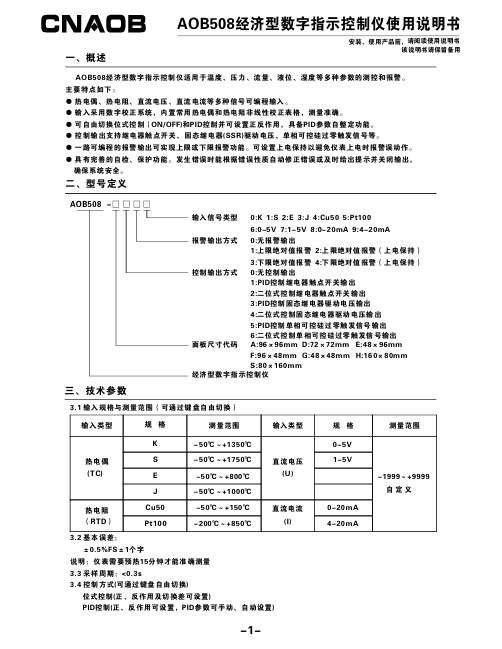
AOB508经济型数字指示控制仪使用说明书安装、使用产品前,请阅读使用说明书该说明书请保留备用AOB508经济型数字指示控制仪适用于温度、压力、流量、液位、湿度等多种参数的测控和报警。
主要特点如下:●热电偶、热电阻、直流电压、直流电流等多种信号可编程输入。
●输入采用数字校正系统,内置常用热电偶和热电阻非线性校正表格,测量准确。
●可自由切换位式控制(ON/OFF)和PID 控制并可设置正反作用,具备PID 参数自整定功能。
●控制输出支持继电器触点开关、固态继电器(SSR)驱动电压、单相可控硅过零触发信号等。
●一路可编程的报警输出可实现上限或下限报警功能。
可设置上电保持以避免仪表上电时报警误动作。
●具有完善的自检、保护功能。
发生错误时能根据错误性质自动修正错误或及时给出提示并关闭输出,确保系统安全。
一、概述二、型号定义1:PID 控制继电器触点开关输出2:二位式控制继电器触点开关输出3:PID 控制固态继电器驱动电压输出4:二位式控制固态继电器驱动电压输出5:PID 控制单相可控硅过零触发信号输出6:二位式控制单相可控硅过零触发信号输出D:72×72mm E:48×96mmG:48×48mm H:160×80mm AOB508-□□□□输入信号类型报警输出方式0:无报警输出1:上限绝对值报警2:上限绝对值报警(上电保持)3:下限绝对值报警4:下限绝对值报警(上电保持)控制输出方式0:无控制输出面板尺寸代码A:96×96mm F:96×48mm S:80×160mm经济型数字指示控制仪0:K 1:S 2:E 3:J 4:Cu505:Pt1006:0-5V 7:1-5V 8:0-20mA 9:4-20mA 三、技术参数3.1输入规格与测量范围(可通过键盘自由切换)输入类型输入类型-1999~+9999自定义规格规格KS E J热电偶(T C)直流电压(U)Cu50测量范围测量范围-50℃~+1350℃-50℃~+1750℃-50℃~+800℃-50℃~+1000℃-50℃~+150℃-200℃~+850℃Pt100热电阻(RTD )0-5V1-5V0-20mA 4-20mA直流电流(I)3.2基本误差:±0.5%FS ±1个字3.3采样周期:<0.3s3.4控制方式(可通过键盘自由切换)位式控制(正、反作用及切换差可设置)PID 控制(正、反作用可设置,PID 参数可手动、自动设置)说明:仪表需要预热15分钟才能准确测量单位:mm四、外形尺寸及开孔尺寸A D E F G H S宽967248964816080高967296484880160宽926845924515276高926892454576152安装开孔尺寸面板尺寸代码高916744904415075深916790444475150宽100100100100100壳体尺寸面板尺寸1001003.5报警方式(可通过键盘自由切换)一路可编程的报警输出可实现上限或下限报警功能(继电器输出)。
DSP数字式步进伺服驱动器DE5080说明书

三、驱动器端口与接线介绍
3.1 端口定义、引线颜色说明 A、电机和电源输入端口
端子号
符号
名称
1
A+
A 相电机绕组+
2
A-
A 相电机绕组-
3
B+
B 相电机绕组+
4
B-
B 相电机绕组-
5
V-
电源输入
6
V+
电源输入
驱动器故障保护后输
8
ALM-
报警信号负输出
出信号给上位机
D、状态指示
绿色 LED 为电源指示灯,当驱动器接通电源时,该 LED 常亮。红色 LED
为故障指示灯,当出现故障时,该指示灯以周期性循环闪烁。红色 LED 在 一
个固定间隔时间后闪烁次数代表不同的故障信息,具体关系如下表所示:
闪烁次数
报警名称
二、电气、机械和环境指标 2.1 电气指标
参数
连续输出电流 输入电源电压(直流)
逻辑输入电流 脉冲频率 绝缘电阻
提供编码器电流
最小值
0 +24
7 0 500
典型值
10 -
最大值
6.0 +80 20 200
50
单位
A Vdc mA kHz MΩ mA
2.2 使用环境及参数
冷却方式
使用环境
保存温度 重量
本驱动器适合于各种中小型自动化设备和仪器,例如:自动锁螺丝机、线 束加工机、自动打孔机、高速绘图仪以及一些自动化装配设备等。在要求噪音 小、运行平稳、高速度响应的设备中应用效果特佳。
技术特点 u 采用全新 32 位电机控制专用 DSP 芯片; u 采用先进的矢量型闭环控制技术,电机运行更平稳、精度更高; u 精确的位置及速度控制,满足苛刻的应用要求; u 根据负载情况采用变流控制技术,降低电机发热; u 具有高动态响应能力,缩短电机加减速时间; u 通过串口外接手编盒调节系统参数,操作方便简单; u 静态电流和动态电流可以任意设置(0---6A 范围内); u 可适配驱动 42、57 或 60 系列混合式闭环步进电机; u 光电隔离信号输入/输出; u 脉冲响应频率最高可达 200KHz; u 提供 16 档通用细分选择,最大 256 细分(51200 脉冲/转); u 提供与各种脉冲源相匹配的电子齿轮(任意细分值); u 具有过流、过热、过压和跟踪误差超差等保护;
Fulltone 驱动器 Pro Distortion Pro DP-1 说明书

Fulltone Distortion Pro TMmodel DP-1Owner’s ManualDesign:The Distortion Pro is designed to cover that huge gap between Overdrive and out-and-out Fuzz. The DP-1 delivers these Hi-Gain sounds with a great amount of flexibility in a very natural, amp-like manner, reacting to your pick attack and cleaning up well when the guitar’s volume knob is backed off. This flexibility is further enhanced by the inclusion of some very powerful Tone shaping knobs, all of which are interactive, allowing the user to create his/her own signature sound. The DP-1 also works well with wah‘s, Univibe type pedals, and already distorted amps. Play on.Features:Volume: This knob determines the output level of the deviceDistortion: determines the overall clipping in the early stages of the circuit.Saturation: an integral knob for dialing in the desired amount of “tube” feel, additional clipping, and sustain. This is interactive with the Distortion knob.Resonance: This shapes the Bass frequencies. You will notice that there is a center detent (reference point) which helps you find your sounds on a dark stage.Voicing: Not a standard Midrange control in that it not only actively varies the overall frequencies, (Low-Mid, Mids, Hi-Mid, and Treble) but it also alters the distortion in these frequencies. Again, there is a center detent as reference point, although this point is not necessarily “neutral” at the 12’Oclock point.Highs: This is used to attenuate or enhance the Treble frequencies. Part of this pedal’s magic is the frequency “overlap” between this and the Voicing knob, allowing for some unusual signature settings.Battery Hatch: Located at the audience-end of the pedal, simply remove the thumbscrew and swing out the door to access your 9 volt battery.9 volt DC port: standard 2.1mm sized barrel jack accepts all Negative center pin9VDC adapters such as Ibanez, Boss, Voodoo Labs Pedal Power, etc.LED “Pilot Light”: tells you when the pedal is “on” and (like all Fulltone pedals) theDP-1 has True Bypass switching, something no other major pedalmaker offers!Page1Browner Sound:I tend to go use old Stratocasters alot on the bridge PU, but am a big fan of the late ‘60s Cream-era Eric Clapton Tones which were Humbuckers through aMarshall 100 watt plexi amplifier.To cop this, Keep the Saturation knob at full CW position and reduce the Voicing knob (CCW) to get a smoother more Violin-like tone reminiscent of EricJohnson and Alan Holdsworth.Increase the Resonance (CW) to simulate a 4x12 cabinet if you use a combo amp. Raise the Voicing and Distortion (CW) and you’re in the Brian May Jimmy Page “Heartbreaker” tonePage always recorded with such a crunchy, Bass-shy tone. By itself it was odd, but in with the rest of the Track is fit like a glove. With the Resonance knob reduced (CCW) and the Voicing raised (CW) you get a very penetrating Midrange. And by backing off a little (CCW) on the Saturation , you get a faster attack on the strings....hence a crunchier, less compressed sound.A little tweak here and there and you‘ve got theAC/DC rhythm sound as well.Cutting Blues Tone:All the controls are interactive, so the slightestchange yields surprising results.Reducing the Saturation (CCW) removes the squashed, compressed Tube feel and can really help the guitar Cut through the mix. For neck PU playing ala SRV, the Resonance control can be reduced to remove any muddiness. As always just experiment...when you get something you like use the Blank Templates on the followingpage to record your discoveries. Sample Sound Settings: Keywords: CW= Clockwise / CCW=Counter clockwise / PU= PickupPage 2Blank Templates. Make multiple copies for Studio and Live notes.Page 3Internal Trimmer Adjustments: Array Warning: these trimmers (located inside the pedal) are set by usat the factory and should not be messed with unless you knowwhat you’re doing and have good reason to mess with them! Youwill find that each one has a small black pen mark notating ourpreferred settings.Trimmer #1: regulates the amount of gain of the firststage in the circuit, rotating this trimmer CCW increasesthe gain. (increasing this setting may cause additionalnoise and/or hiss)If you are using humbuckers or higher-gained Pickupsyou may want to reduce the amount of gain here byturning it slightly CW if more clarity and definition isdesired. (no more than 1/8 turn)Trimmer #2: controls the overall maximum availableMidrange and Distortion of the W increases theoverall mids and Gain, CW decreases it. Please note thattoo much of this increases noise and lessens the pedal’sability to clean up when the guitar’s volume knob isbacked-off. In other words, we set it here and there’s noneed for you to mess with it really!Warranty:This pedal carries a 5 year warranty (1 year for switch) for the original purchaser thatcovers all repairs due to manufacturer error only. It does NOT cover any damage fromuser/owner mishandling, shipping, acts of God, and abuse. Owner is to contact Fulltonedirectly for all repairs, and any work done by anyone other than Fulltone voids the warranty.All shipping costs are the responsibility of the owner, and are to be paid in advance of anywork performed on pedal. This warranty is not transferable, and is good to the originalpurchaser of the pedal only, who may be asked to provide a copy of the sales receipt forverification. There is NO walk-in traffic at Fulltone. All items must be sent via mail, UPS, orFederal Express.Disclaimer:The Owner or user assumes all responsibility for death, injury, and/or damages relating tothe operation of this device Fulltone Musical Products Inc. assumes no responsibility fordeath, injury or damages relating to the operation of this device.Contact:Fulltone Musical Products Inc.4220 Glencoe Ave. Marina del Rey, CA 90292310.821.4500fax 821.4511********************Page 4。
DP4535-02-DI L18 用户手册说明书
DP4535-02-DIL18User manualTABLE OF CONTENTSTABLE OF CONTENTS ___________________________________________________________________ 2 WARNINGS ____________________________________________________________________________ 3 EQUIPMENT ___________________________________________________________________________ 4 DESCRIPTION __________________________________________________________________________ 5 PRESET _______________________________________________________________________________ 6 ACCESSORIES _________________________________________________________________________ 8 ARRAY EQ ____________________________________________________________________________ 10 MAINTENANCE ________________________________________________________________________ 11 TECHNICAL SPECIFICATIONS ___________________________________________________________ 13 USER NOTES _________________________________________________________________________ 14Page 2 / 16L18WARNINGSL18Page 3 / 16PRECAUTIONSDo not open the speaker, do not try to disassemble it neither to modify it in any way. The system doesn’t include any user -repairable part.If the system seems to be malfunctioning or damaged, stop using it at once and have it repaired by a NEXO qualified technician. Do not expose the system directly to the sun or to the rain, do not immerse it into fluids, do not place objects filled with liquid on the system. If a liquid gets into the system, please have it inspected by a NEXO qualified technician. The connection should be performed by qualified technician, by ensuring that power is off.Operating temperature with temperate climate: 0°C to +40°C (+32°F to +104); -20°C à +60°C (-4°F to +140°F) for storage.SAFETY INFORMATIONSRead this manual before using the speaker. Keep this manual available for further reference. Observe all warnings and cautions.Please check the NEXO Web site to get the most up-to-date version of this manual.Ensure you are aware of the safety rules applying to rigging, stacking or installing on tripod or speaker stand. Failure to observe these rules may expose persons to potential wounds or even death. Only use the system with accessories specified by NEXO.Please always consult a NEXO-accredited technician if the installation needs architectural works and observe following precautions: Mounting Precautions :- Please select screws and mounting location supporting 4 times the system weight.- Do not expose the system to excessive dust, vibrations, to extreme cold or hot temperatures, to reduce the risk of damaging components.- Do not place the system in an unstable position: it could fall accidentally.-If the system is used on a tripod, please ensure the tripod’s specifi cations are adapted and that its height does not exceed 1.40m/55”. Do not move the tripod with the system in position .Connection and Powering Precautions:- Unplug connected cables before moving the system. - Power off the system before connecting the system.- When switching on the installation, the amplifier must be powered last; when switching the installation off, shut off theamplifier first.- If you work by cold temperatures, progressively raise the level to nominal value during the first minutes of use, to allow thesystem components to stabilize.Please check regularly the system condition.HIGH SOUND PRESSURE LEVELSExposure to very high sound pressure levels may cause permanent hearing losses. Degrees of hearing losses may be different from one person to another, but almost everybody will be affected if exposed to high sound pressure levels during a long period of time. The OSHA (Occupational Safety and Health Administration) American Agency specified the following maximal exposures:WASTE OF ELECTRIC OR ELECTRONIC EQUIPMENTThis symbol on the product or its packaging indicates that this product must not be treated as household waste. Instead, it is your responsibility to hand it over to a designated collection point for the recycling of waste electrical and electronic equipment. By ensuring your waste equipment is recycled, you will help preventpotential negative consequences for the environment and human health, which could appear if this product was not recycled. Recycling helps spare natural resources. For more information about the recycling of this product, please contact your local city office, your household waste disposal service or your reseller.Equipment3 locations for hanging, 1 on the top for speaker stand and on both side.Assembly on distance rod or speaker standPage 4 / 16L18DESCRIPTION→The L18 is a compact and powerful subwoofer, ideally complementing PLUS serie speakers→The L18 subwoofer is equipped with two Speakon NL4 connectors, with parallel-wired pins,→ L18 uses the 1+/1- pins, (2+/2- through).→Amplification•The L18 subwoofer must be used with a NEXO processor to handle EQ, phase alignment, crossover and excursion/thermal protection for the system loudspeaker.•The following table shows the number of L18 subwoofers usable with each solution.(a) NXAMP4X1mk2 (BRIDGED)L18Page 5 / 16PRESETThere are two setting range for surrounding speaker L18:→“OMNI” Setups; For a traditional use of the subwoofer in omnidirectional radiation (require at least one subwoofer and a channel of amplifier).•Omnidirectional Main setup, with low-pass at 60, 85 or 120 Hz.•Omnidirectional Monitor setup, with low-pass at 60, 85 or 120 Hz.→“CARDIO” Setups; For a directional use (cardioid) of subwoofers (require at least two subwoofers and two channels o f amplifier).•Cardioid back and front setups, with low-pass at 60, 85 or 120 Hz.- Setup « FR » (Front) for the subwoofer pointed at the audience.- Setup « BA » (Back) for the subwoofer turned around.•The ideal ratio for a directional use is 2x L18 in CARDIO FRONT mode on top of 1x Reversed L18 in CARDIO BACK mode. From 1:1 to 3:1 ratio can be used.Page 6 / 16L18PRESETL18Page 7 / 16W ith P15 in front of houseACCESSORIESPage 8 / 16 L18VNI-CLADAPT (PNI-CLADAPT)Ceiling adapter, use with LNU-HBRK18.Screw CLADAPT to the ceiling (fasteners not provided).Place the assembly on CLADAPT, use the 2 guides. Tight with the fasteners provided with CLADAPT.Refer to the Product Data Sheet.ACCESSORIESL18Page 9 / 16LNI-3L18L18 Rigging system (up to 3; Cardio or Omni)Refer to the Product Data Sheet.LNT-WB18WheelboardRefer to the Product Data Sheet.LNT-COV18: COVER FOR L18 ON WHEELBOARDARRAY EQPage 10 / 16 L18The ArrayEQ allows to adjust the system frequency response in its lower range(see curves below, with different ArrayEq values):50100005001k k5k10k0kFrequency ( )1 1 14 1 104 0 4 101 Array (d ) ad ustinMAINTENANCE Grille Changing: Remove 8 screws18’’ DriverRemove 20 screws Remove the trapRemove 8 screws, 2 inside with a curved screwdriver. Remove the driver.MAINTENANCEPlace 8 screws.Tightening torque: 3.0 Nm (Thread Locker: Loctite 242)Follow the sequence below to tight the screw.Place and tight the 12 others screws.Spare partsTECHNICAL SPECIFICATIONS L18 WITH NEXO ELECTRONICSSPECIFICATIONSUSER NOTESNEXO S.A. Parc d’activité de la Dame JeanneF-60128 PLAILLYTel: +33 3 44 99 00 70 Fax: +33 3 44 99 00 30 E-mail:************。
得力DL-888D标签打印机用户手册 说明书
标签打印机DL-888DDL-888T用户手册目录手册信息 (1)打印机常见问题排查 (2)1、打印不清晰 (2)2、打印跳标、定位不准 (2)3、清洁打印头 (3)4、清洁传感器、胶辊和纸张路径 (4)安全须知 (5)第1章产品简介 (8)1.1 开箱清单 (8)1.2 外观及组件 (9)1.3 产品尺寸 (10)第2章产品规格 (11)第3章安装和使用 (13)3.1 安装介质 (13)3.1.1 安装纸卷 (13)3.1.2 安装折叠纸 (16)3.1.3安装外置纸卷支架 (18)3.1.4安装碳带(只适用DL-888T) (19)3.2 电源连接 (21)3.3 接口连接 (22)3.4 标签侦测 (22)3.5 操作面板 (23)3.6 基本功能使用 (24)3.6.2 走纸 (24)3.6.3 打印测试 (24)3.6.4 标签学习 (25)3.6.5 机器使用的纸张 (25)第4章接口 (28)附录1:电子信息产品污染控制的说明 (29)手册信息本用户手册包含产品使用、安装等基本信息。
以下手册对各种技术问题和领域有更为详细的介绍。
打印机常见问题排查1、打印不清晰1.清洁打印头,清洁参考步骤3、清洁打印头;2.调高打印机的打印浓度,通过调节选项页签下的深度,数值越大浓度越浓,如下图所示:3、不要使用尖锐物品触碰打印头,打印时确保纸张光洁平整、表面无细小颗粒物质,避免打印过程中划伤打印头造成打印不清晰。
2、打印跳标、定位不准1.更换纸张未进行标签学习,标签学习方法参考3.6.4标签学习一章内容;2.编辑软件纸张规格参数设置与实际不符,使用直尺测量标签纸大小及标签的左右及上下间隙,确保编辑软件输入的规格与实际标签纸一致;3.传感器脏污、清洁传感器,如下图所示:3、清洁打印头灰尘、异物、粘性物质或其他粘连在打印头或打印机内的污染物可能会降低打印质量。
脏污时请按以下方法清洁打印头。
※ 注意事项1)清洁前务必关闭打印机电源。
V-EA 系列 - UL508 手动电动机控制器说明书

10
Thermal Overload
4
“Must Trip” < 1 hr = 145% RC
“Must Not Trip” > 1 hr = 113% RC
1
Voltage Rating
Short Circuit Withstand Rating (UL/CSA - Ratings) Group Short Circuit Withstand Rating (UL/CSA - Ratings) Interrupting Capacity (VDE - Ratings) Calibration Temperature Operating Temperature Storage Temperature Terminal Size Acceptability Terminal Torque Terminal Protection Degree
480Y/277VAC 0.3-25A: 1 pole - 42VDC; 2 Pole - 80VDC 30-60A: 1 pole - 24VDC; 2 Pole - 60VDC 0.3-60A (RC): 10kA with UL-listed RK5 back-up fuse or MCCB 0.3-10A (RC): 10kA; 13-60A (RC): 5kA no branch circuit protection required 0.3-63A (RC): 10kA 40°C (104°F) -25°C to 55°C (-13°F to 131°F) -40°C to 70°C (-40°F to 158°F) Top: 18-3 AWG; Bottom: 18-2 AWG (Line/Load reversible) 20 lb.in. IP20
- 1、下载文档前请自行甄别文档内容的完整性,平台不提供额外的编辑、内容补充、找答案等附加服务。
- 2、"仅部分预览"的文档,不可在线预览部分如存在完整性等问题,可反馈申请退款(可完整预览的文档不适用该条件!)。
- 3、如文档侵犯您的权益,请联系客服反馈,我们会尽快为您处理(人工客服工作时间:9:00-18:30)。
无锡信捷电气股份有限公司资料编号DC16 20131007 1.0DP-508D、DP-508D-L细分驱动器用户手册1、产品概述 (1)1-1. 性能特点 (1)1-2. 应用领域 (1)1-3. 电气特性 (1)2、使用指导 (2)2-1. 安全事项 (2)2-2. 连线注意点 (2)2-3. 安装环境 (2)3、接口和功能介绍 (3)3-1. 控制信号接口 (3)3-1-1. 控制信号接口功能描述 (3)3-1-2. 控制信号时序图 (3)3-1-3. 输入电路及相关要求 (4)3-2. 功率接口 (4)3-2-1. 强电接口功能描述 (4)3-2-2. 供电电源要求 (5)3-2-3. 与电机接线 (5)3-3. 功能设定 (5)3-3-1. 电流设定 (6)3-3-2. 细分设定 (6)3-4. 保护功能 (6)4、尺寸、安装及典型接线 (8)4-1. 尺寸 (8)4-2. 安装 (8)4-3. 典型接线 (8)5、故障诊断和排除 (10)6、电机选配 (11)iDP-508D、DP-508D-L细分驱动器用户手册iiDP-508D、DP-508D-L细分驱动器用户手册DP-508D、DP-508D-L细分型步进驱动器,最大输入电压可达80VDC,输出电流5.0A,推荐驱动5.0A以下86系列二相混合式步进电机,该产品采用纯正弦波电流控制技术,使电机运行平稳,噪声小,特别适用于激光打标机、数控机床等分辨率较高的小型数控设备上。
1-1.性能特点⏹超低电机运行噪声⏹供电电压可达80VDC⏹输出电流有效值可达5.0A⏹细分动态可选,最高达200细分⏹推荐驱动任何5.0A以下86系列两相步进电机⏹光隔离信号输入⏹电流设定方便,任意档可选⏹具有短路保护、过压保护、过流保护功能1-2. 应用领域适用于各种中小型和自动化设备及仪器,如:气动打标机、贴标机、割字机、激光打标机、绘图仪、小型雕刻机、数控机床、拿放装置等。
在用户期望低振动、小噪声、高精度、高速度的小型设备中效果尤佳。
1-3. 电气特性1DP-508D、DP-508D-L细分驱动器用户手册请于安装使用驱动器前,仔细阅读本节,并严格遵守!2-1. 安全事项⏹驱动器必须由专业技术人员进行安装和操作!⏹驱动器未接电机前严禁通电!否则可能造成触电危险,并且驱动器会报警。
⏹驱动器的输入电压必须符合技术要求!⏹严禁带电对电机或驱动器进行设置和测量!⏹驱动器必须在断电3分钟后,才能再次进行接线、安装和参数设置!⏹通电前,请确保电源电缆、电机电缆、信号电缆连接的正确性和牢固性!⏹避免电磁干扰!2-2.连线注意点⏹信号电缆和电机电缆必须带屏蔽,分别走线,距离越大,抗干扰越好。
⏹电机电缆双端屏蔽,一端接电机外壳,另一端接驱动器GND端子。
⏹严禁带电插拔输出端子,容易导致驱动器损坏。
2-3.安装环境⏹避免将驱动器安装在其他发热设备旁。
⏹避免在粉尘、油雾、腐蚀性气体、湿度太大及强震动场合使用。
⏹上位机、驱动器、电机的接地线要与地有大面积接触,确保良好的导电性,接地电阻小于2Ω。
2DP-508D、DP-508D-L细分驱动器用户手册3-1. 控制信号接口3-1-1. 控制信号接口功能描述3-1-2. 控制信号时序图为保证系统响应的可靠性,我们对各控制信号作如下要求:⏹信号高电平时要求24V有效(DP-508D-L为5V有效),低电平时要求小于0.5V有效。
⏹ENA(使能信号)应提前DIR(方向信号)至少3s变为高电平。
⏹确保DIR (方向信号) 领先PUL(脉冲信号)下降沿至少5μs建立。
⏹脉冲宽度不能小于1.2μs。
⏹脉冲低电平持续时间不能少于1.2μs。
3DP-508D 、DP-508D-L 细分驱动器用户手册4时序图具体如下:3-1-3. 输入电路及相关要求介绍驱动器输入电路的共阳极接法,示意图如下:输入要求⏹ 所有输入信号均通过光电隔离,为确保内置高速光耦可靠导通,要求提供控制信号的电流驱动能力至少8mA 。
⏹ 驱动器内部已串入光耦限流电阻,各控制信号一般接+24V (DP-508D-L 接5V )。
3-2. 功率接口3-2-1. 强电接口功能描述DP-508D 、DP-508D-L 细分驱动器用户手册53-2-2. 供电电源要求⏹ 电源电压切勿接反!⏹ 电源工作范围:35~80VDC ,保证驱动器正常工作。
⏹ 电源宜采用非稳压型直流电源,电源输出能力应大于驱动器设定电流的60%。
⏹若使用稳压型开关电源供电,电源的输出电流范围需大于电机工作电流。
3-2-3. 与电机接线注意:当驱动器与电机采取不同接线时,电机的运行效果有很大区别。
通常,驱动器的供电电压决定了电机运行的高速性能(供电电压越大,高速力矩越大,可有效避免失步),设定电流值决定了电机的输出力矩(设定电流越大,电机输出力矩越大)。
但是,供电电压大时,低速运转时的振动也较大;设定电流值大时,驱动器和电机的发热都很严重。
因此,在实际使用中,用户应根据自身需要,采取合适的连接方式,以达到满意的效果。
下图列举了几种连接方式和设定要点,仅供用户参考: ⏹ 8线并联模式:设定电流值应为电机额定电流值的1.4倍; ⏹ 8线串行模式:设定电流值应为电机额定电流值的70%;⏹ 4线、6线高速模式:设定电流值要小于或等于电机的额定电流值; ⏹ 6线高力矩模式:设定电流值应为电机额定电流值的70%。
A+A-B+B-A+A-B+B-A+A-B-NC NC A+A-NCB+NC八线电机串行接法(低速力矩大)八线电机并行接法(高速性能好)四线电机六线电机高力矩模式六线电机高速模式B-B+A+A-3-3. 功能设定驱动器采用五位拨码开关设定半流/全流和细分精度。
具体功能设定如下: SW1:设定半流/全流(SW1=OFF :半流状态;SW1=ON :全流状态); SW2~ SW5:设定细分精度。
DP-508D、DP-508D-L细分驱动器用户手册3-3-1. 电流设定用单圈电位器可设定0~5.0A之间任意电流级别,见下图所示:3-3-2. 细分设定细分精度由SW2~SW5四位拨码开关控制,详细设置如下表所示:3-4.保护功能⏹状态指示灯电源指示灯PWR:绿灯亮时,正常工作状态;报警指示灯ALM:红灯亮时,进入报警状态,说明此时出现了过压、过流或短路;红灯等间隔闪烁时,为过压报警,红灯常亮为过流或短路报警;。
⏹故障输出当驱动器出现过压、过流或短路时,由ERR、COM端子输出故障信号。
集电极开路输出。
⏹过流、过压、短路保护当电源电压大于上限电压(95V)、电机电流大于设定值的120%或者电机相线之间短路时,保护电路采取保护措施,关断PWM输出,报警指示灯给出相应报警信息。
6DP-508D、DP-508D-L细分驱动器用户手册注意:当以上保护电路动作后,驱动器无法正常工作,只有消除故障,重新上电,电源指示灯变绿后,方可使驱动器恢复。
7DP-508D 、DP-508D-L 细分驱动器用户手册84-1. 尺寸DP-508D 、DP-508D-L 外形尺寸如下图所示:4-2. 安装驱动器应安装在通风良好,防护妥善的电柜内,并定期检查散热风扇运转是否正常。
为保证驱动器散热条件,请按至少10cm 以上空间间距安装。
安装时要避免粉尘和杂物落入驱动器内部。
4-3. 典型接线单位:mmDP-508D、DP-508D-L细分驱动器用户手册注意:用户在接线时,应遵循功率线(电机相线、电源线)和弱电信号线分开的原则,以避免控制信号受到干扰。
9DP-508D、DP-508D-L细分驱动器用户手册10DP-508D、DP-508D-L细分驱动器用户手册DP-508D、DP-508D-L型适用于86系列两相混合式步进电机。
一般说来,电机的选择主要看电机扭矩和额定电流两方面。
扭矩的大小取决于电机的尺寸,尺寸大的电机扭矩也大;电流大小主要取决于电感,小电感的电流较大,电机高速运转时性能较好。
对于某一给定接法的电机来说,电机的工作电流越大,输出转矩越大,电机发热也较严重;驱动器的供电电压越大,电机高速扭矩也越大;电机高速运行时的扭矩比中低速运行时的扭矩要小。
11无锡信捷电气股份有限公司江苏省无锡市蠡园开发区滴翠路100号创意产业园7号楼四楼邮编:214072电话:(0510) 85134136传真:(0510) 85111290 WUXI XINJE ELECTRIC CO., LTD.4th Floor Building 7,Originality Industry park, Liyuan Development Zone, Wuxi City, Jiangsu Province 214072Tel: (510) 85134136Fax: (510) 85111290。