自动气柜操作手册
气柜操作模块培训手册【范本模板】
气柜操作模块培训手册一、气柜概况油品管理处原油车间南北火炬岗位各设置一台50000m3干式气柜.北火炬为1#气柜,5004年8月30日投入使用。
南火炬为5#气柜,5010年10月15日投入使用.两台气柜均采用威金斯式橡胶膜密封型干式气柜,此类型气柜密封结构已在石化行业广泛应用。
二、气柜的分类气柜分为干式和湿式两种,用于贮存各种工业气体。
可以分为低压气柜和高压气柜两大类.前者又有湿式与干式两种结构。
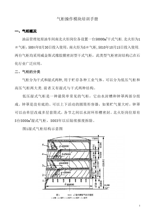
低压湿式气柜是一种最简单常见的气柜,它由水封槽和钟罩两部分组成。
钟罩是没有底的、可以上下活动的圆筒形容器,如果贮气量大时,钟罩可以由单层改成多层套筒式,各节之间以水封环形槽密封。
北火炬岗位原有5台5000m3湿式气柜,5003年以后陆续报废拆除。
图1湿式气柜结构示意图低压干式气柜又分为曼式和威金斯式。
曼式气柜是一种立式油密封多边形的活塞式气柜,主要用于储存和配送工业气体。
当气柜进气时,气柜活塞水平上升;反之,当气柜放气时,气柜活塞水平下降,活塞与柜壁间的间隙是用油进行密封,密封油的选用是关键.图2曼式气柜结构示意图威金斯式气柜(美国WIGCINS公司专利),亦称卷帘密封型干式气柜,其密封形式主要不同是柜体侧板与T挡板、T挡板与活塞之间用橡胶密封膜连接,在活塞上、下移动时密封橡胶膜随之卷起或放开。
密封膜应具有耐久性、气密性、弹性和一定强度,且能适应较广泛的温度范围(—50~80℃).具有结构合理、容量大,操作维护简便等特点,是一种新型、节能、环保型气柜,运行平稳,安全可靠,适用于储存炼厂尾气。
国内最大的干式气柜已达50万m3。
南北火炬目前在用的气柜为威金斯式气柜,容量为50000m3。
下面主要简绍威金斯式干式气柜。
三、干式气柜结构3。
1威金斯干式气柜的结构卷帘型干式气柜主要由柜壁、底板、柜顶、活塞、T型围栏、调平装置、紧急放散装置、柜容显示装置、橡胶密封膜等部分组成。
它具有占地面积小、活塞升降平稳、维护费用低、操作方便等特点。
气柜操作简介
点Pre-Purge键开始前吹,完成后 示灯变亮 此时可以拆除钢瓶,进行更换 安装完毕后,点Post-Purge开始后吹,完成后 指示灯变亮 打开钢瓶阀, 健,确认备用状态 如若需要立刻供气,点击
指
指示灯闪烁,点击Standby按 即可实现
其他按键简介
当设备断电后需要快速供气或因其他原因需 要重新走系统流程时必须先将设备进行复位 强制复位键常按7秒以上方能产生效果 在任何情况下按下强制复位7秒以上都能将系 统恢复至初始状态
注意:1.在供气时进行强制 复位将导致设备停止运行 2.强制复位之后设备 (左/右)盘面所有气动阀 关闭
注意:非必要 情况请按照设 备正常流程进 行运行 当设备断电复位需要快速供气时可使用此按钮 在进行紧急供气之前必须确认钢瓶阀门处于关闭状态 按下紧急供气前必须确认对应调压阀处于开启状态 必须要在系统初始状态在方能按下紧急供气键,常按7秒 以上方有效果
气柜操作
NH3
第一部分:NH3
操作盘面认识
操作流程简介 Pre-Purge(前吹) Change(钢瓶更换) Post-Purge(后吹) Standby(备用状态) Process(Supply状态)
流程状态描述 注意:1. 处于长亮状态
2.钢瓶阀处于关闭状态
EMO按键具有以下功能与特性
1.EMO的电路是独立的,不受其他干扰的 2.当EMO被按下之后,所有的气动阀将被关闭 3.需要复位EMO时,只需将开关顺时针旋转即可
注意:1.当EMO被按下之后设备 想要恢复运行必须将EMO键复位 2.正常情况下,严禁碰触此 按键
磅秤参数设置
长按 ,进入设臵选择项,显示A1 按下 ,选择设臵项,如A2/A3· · · 按下 ,进入数据设臵 ,显示切换重量 按下 ,调高数值;按下 调低数值 设臵完毕,按下 退出,也可让其自行退出
气柜操作规程完整

20000n?橡胶膜密封干式气柜操作规程20000m3橡胶膜密封干式气柜技术操作规程第一节、主要技术参数: 1、3橡胶膜密封干式气柜主要技术参数2、工作原理及结构说明2.1工作原理橡胶膜密封干式储气柜是采用橡胶膜密封的,气柜是由侧板、立柱、顶架、顶板、活塞、密封橡胶膜、活塞调平装置、环形走道、斜梯等部件组成。
该柜的外壳是由侧板、支柱、罐顶及顶板构成一个固定圆柱形几何体,其部有一个可活动的活塞,侧板、T围栏与活塞之间的密封采用橡胶膜密封。
2.2结构说明(1)柜体圆形柜体壁板外设加强角钢,外部斜梯沿柜壁可通达环形走道和柜顶,斜梯各休息平台外设置检修门供工作人员进入柜检修,柜壁上部设置通风孔,当活塞上、下运行时形成气流,使活塞上部通风。
煤气进出气管设在壁板下部。
壁板加强角钢与立柱连接,立柱采用H型钢或工字钢制作,并已考虑施工荷载,立柱下端设置柱脚以便与基础锚固。
(2)柜顶顶架由拱梁组成,上铺顶板。
柜顶设通风帽。
柜顶外缘各立柱轴线位置设置人孔,供吊装橡胶密封膜使用。
(3)活塞活塞板做成与底板相同的形状,即拱顶形,并且做成最适合于承受部气压的形状。
活塞外缘设置混凝土围环(混凝土坝)。
活塞板上设置人孔,供检修人员进入活塞下部柜,外圈设环形走道。
(4)调平装置调平装置是使上下升降的活塞自动达到水平状态的装置,各用两根钢丝绳将活塞径向对称点与外部配重块连接起来,当活塞倾斜时,受拉的一段钢绳会反方向的对活塞的倾斜自动校正,起到自动调平作用。
(5)密封装置密封装置由密封型钢(角钢或槽钢)、密封膜、压板、C型导向卡、螺栓等组成。
3、气柜系统仪表、报警控制联锁系统:(1)柜容测量显示气柜容量达80%时,控制系统发出“气柜容量上限”报警指示、并发出声光报警。
(根据实际生产情况设定)柜容测量显示气柜容量达85%时,控制系统发出“气柜容量上上限” 报警指示、并发出声光报警,进口阀门自动关闭。
(根据实际生产情况设定)(2)柜容测量显示气柜容量达15%时,控制系统发出“气柜容量下限”报警指示、并发出声光报警;(根据实际生产情况设定)柜容测量显示气柜容量达10%时,控制系统发出"气柜容量下下限”报警指示、并发出声光报警,同时气柜出口阀自动关闭、加压机自动停止。
300气柜参数及操作说明
储气柜介绍、参数及储气柜操作要点一、简介(一)气柜种类及结构形式气柜是沼气和混合气的储存设备。
它用来调节沼气高低不均匀的供气负荷。
气柜实际上就是储气柜,按储气压力大小可分为低压储气柜和高压储气柜两种。
低压储气柜按密封方式分类为:湿式和干式两种,湿式有直立式和螺旋式;干式气柜是利用弹性垫片及油封填充方法,保持密封,目前使用很少。
高压气柜通常称为高压储气罐。
有圆筒形(立式或卧式)和球形。
1、低压湿式气柜低压湿式气柜主要由水槽和钟罩组成,钟罩分为数节(可随沼气输入输出而升降),按升降方式不同,可分为直立式和螺旋式两种。
下面介绍几种常用的低压湿式气柜结构。
(1)直立式低压湿式气柜。
由水槽、钟罩、塔节、水封、顶架、导轨立柱、导轮、配重及防真空装置等组成。
(2)螺旋式低压湿式储气柜。
低压湿式螺旋气柜的结构由水槽、塔节、钟罩、导轨、平台、顶板和顶架、进出气管等部分组成。
气柜本体由钢板拼焊成。
直立式气柜安设有立柱式导轨,每个塔节靠其导轨与相邻塔节上的导轮相互滑动而缓慢旋转上升或下降,如套筒式结构,但不能承受强烈风压,故在风速太大的地区不应采用。
(二)湿式气柜制作安装施工方法1、气柜的预制气柜的安装速度和质量很大程度上与预制的质量有关,搞好气柜的预制是保证质量、加快安装速度的重要前提。
预制阶段的工作包括:底板条板与带板预制、上水下水封预制、角钢圈、槽钢圈、立柱及拱顶骨架的预制、导轨预制。
2、气柜安装及施工方法低压湿式气柜钟罩和水槽壁的组装有倒装法和正装法。
目前常用的施工方法是正装法,根据各单位的施工条件和现场情况,气柜的正装法施工分为两种,一种是机械配合正装法,第二种是起重机机械配合水浮正装法。
3、气柜安装质量检验(1)施工过程中的焊接质量检验。
焊接规范要求。
(2)气柜底板的严密性试验。
气柜底板严密性试验同样是为了检查底板结构强度和焊缝的严密性。
底板的严密性试验可采用真空试漏法或氨气渗漏法。
(3)气柜总体试验。
二、300立方米低压湿式储气柜参数:1、公称容积:300立方米2、直径:9.8米3、升起高度:10.58米4、总重:35 吨5、压力:3000Pa6、基本风压:50Kg/平方米7、基本雪压50Kg/平方米三、操作要点:净化冷沼气的生产工艺流程中,有的为了稳定沼气压力和沼气质量,往往在沼气汇总管上(在沼气增压机前)增设一个300立方米沼气储气柜。
气柜工段操作规程
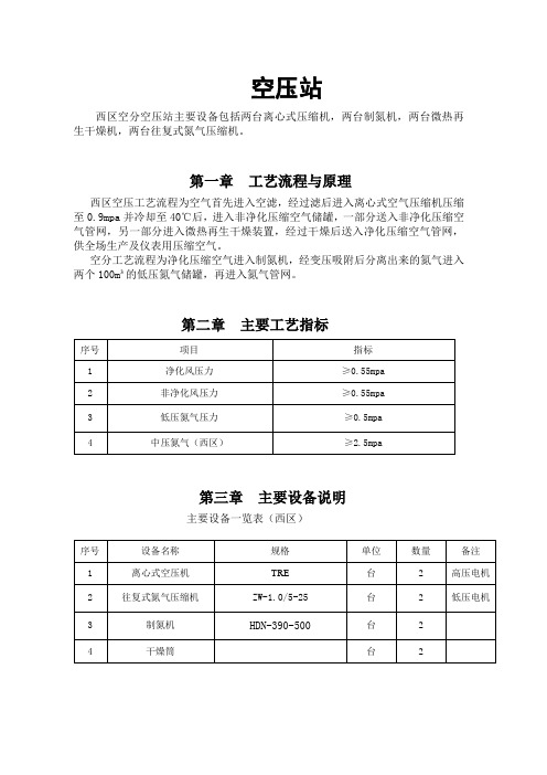
空压站西区空分空压站主要设备包括两台离心式压缩机,两台制氮机,两台微热再生干燥机,两台往复式氮气压缩机。
第一章工艺流程与原理西区空压工艺流程为空气首先进入空滤,经过滤后进入离心式空气压缩机压缩至0.9mpa并冷却至40℃后,进入非净化压缩空气储罐,一部分送入非净化压缩空气管网,另一部分进入微热再生干燥装置,经过干燥后送入净化压缩空气管网,供全场生产及仪表用压缩空气。
空分工艺流程为净化压缩空气进入制氮机,经变压吸附后分离出来的氮气进入两个100m³的低压氮气储罐,再进入氮气管网。
第二章主要工艺指标第三章主要设备说明主要设备一览表(西区)第四章空压机岗位操作法制氮机1.制氮机的开机步骤1)保证空压机供气源压力在0.6mpa以上。
2)给制氮机送电,检查各阀门的开闭情况。
3)缓慢打开进口阀,待储气罐中压力升至0.6mpa以上时按启动按钮。
4)打开出口放空阀。
5)观察氮气纯度指示屏,等待升至系统需求纯度。
6)待升至需求纯度后,打开制氮机出口阀,关闭放空阀。
保证管网在需求的压力和纯度之上。
2.制氮机的停机步骤1)关闭制氮机出口阀。
2)按下控制仪上停止按钮。
3)关闭制氮机进口阀。
4)打开罐底部各排凝将罐内积水排出。
第五章离心式压缩机简介TRE 型压缩机是一种内置齿轮增速系统的高速多级透平压缩机。
具有经济和高可靠性而广泛使用作为各种气体的气源的压缩机。
TRE 型压缩机是一种具有极其紧凑的组装结构式的压缩机,包括压缩机主体,主电机,润滑系统,进气过滤器,中冷器,后冷器和安装在同一机体上的控制面板等部分组成。
它的旋转部件几乎完全无振动,因为它的转子做了很好的动平衡和静平衡。
由于这些优点和其他一些功能,诸如机械部件磨损小和坚固耐用的特点,确保这种压缩机在整个使用时间周期内可以安全使用。
即使经过长期使用,其原始性能也不会发生降低。
TRE型压缩机是技术水平先进的透平压缩机。
能产生无油压缩空气,具备320KW~1000KW功率和 3750 m3/h~10500 m3/h流量范围的工作能力。
气柜安全操作规程

造气车间气柜安全操作规程一气柜构造:气柜为两塔节直升式气柜,容积10000m3。
气柜由钟罩、中Ⅰ节、中Ⅱ节、水槽四部分组成,均由钢板焊接而成,钟罩顶部为圆弧形。
顶部设有放空管、放空阀、取样阀,四周置有平衡重锤均匀分布于钟罩边缘,中Ⅰ节上下均有环形水封,钟罩、中Ⅰ节,中Ⅱ节均有14个导轮,水槽上环形导轨14根,进出口均设有两个水封,进出口水封槽,进出口溢流水封。
正常生产时溢流水封,主要作用是将气体中夹带的冷凝水及时排掉,由进出口溢流水封溢流出满足连续生产,防止冷凝水积存一定高度,进出口管会被冷凝水水封,使煤气出不去,为了克服此现象而设溢流水封。
二气柜工作原理:设钟罩和重锤总重为G,设进气压力P,作用于整个钟罩顶部的力为G1,则G1=PF=G。
加上对钟罩的浮力,故当进气时气柜能沿导轨上升。
但当气柜输入气量小于出气量时,气体内气体减少,气体密度降低,压力下降。
这时气柜在自重量作用下沿导轨下降,气柜内的压力恢复至原来的压力时,气柜就停止下降。
气柜进出口有水封槽,依靠溢流管的溢流作用,使水槽内的水保持一定的高度,水槽内有两根管道伸出水面。
一根为进气管,另一根为出气管。
向气柜送气前中Ⅰ节、中Ⅱ节的环形水封保持一定高度的水位,水槽内水位保持溢流。
当气柜内气量增加时,钟罩、中Ⅰ节、中Ⅱ节先后上升,反之先后下降。
钟罩顶部设有安全罩,当钟罩下降到最小容积时,安全罩在出气管的管口上,安全罩的下部浸入水面形成水封,可防止将钟罩抽瘪,钟罩上部装有安全放空管,当气柜较低时,安全放空管的下部浸入水面,气柜内的气体不能排出,当气柜上升过高时,安全放空管下部离开水面,气柜内的气体能自动从放空管放空,防止钟罩上升过高被顶翻。
气柜的进出口管均有水封,以便停车时和前后系统隔离。
气柜操作规程
气柜操作规程
《气柜操作规程》
一、气柜的基本概念和作用
气柜是一种用于存储气体并调节气压的设备,通常用于工业生产、实验室、采矿和石油等领域。
气柜的主要作用是存储和保持所需的气体压力,并确保气体在使用时能够达到需要的压力和流量。
二、气柜的操作流程
1. 开启气柜前,首先需要检查气柜的安全阀和压力表是否正常工作。
确保气柜内没有气体泄漏和压力异常。
2. 打开气柜阀门时,应当先打开缓慢放气,确保气体缓慢释放,避免因气压突降造成设备损坏或人身伤害。
3. 在使用气体时,需要根据需要调节气柜的压力,确保输出的气体压力和流量符合使用要求。
4. 操作完毕后,关闭气柜的阀门,并确保气柜内气体全部放完后再关闭。
这样可以确保气柜内不会残留有害气体导致安全隐患。
三、安全注意事项
1. 气柜操作时,应当戴好安全防护装备,包括带有防毒面具、手套和护目镜。
以防止意外事故导致人身伤害。
2. 在操作气柜时,应当严格按照操作规程进行,不要随意调节压力和阀门,避免设备损坏和人身伤害。
3. 操作完毕后,应当及时将气柜内的气体排放完毕,并关闭阀门。
确保气柜内不会残留有害气体。
四、定期检查和维护
为确保气柜的正常运行和安全使用,需要定期对气柜进行检查和维护。
包括检查阀门是否正常、安全阀和压力表工作是否正常、气柜内是否有气体泄漏等。
同时也需要对气柜进行清洁和润滑。
以上为《气柜操作规程》的基本内容和要点,希望对气柜的安全操作有所帮助。
在日常操作中,一定要严格遵守规程,并做好安全防护,确保气柜的正常运行和使用。
压缩机、气柜操作规程_0

目录第一篇装置简介――――――――――――――――――――――――――――――― 1 工艺流程说明――――――――――――――――――――――――――――― 2第二篇第一部分气柜岗位操作法-――――――――――――――――――― 5第一章系统简介性能指标――――――――――――――――――――――― 6 第二章岗位操作法――――――――――――――――――――――――――7 第三章停车操作―――――――――――――――――――――――――――8 第四章异常情况处理―――――――――――――――――――――――――10 第五章安全操作注意事项―――――――――――――――――――――――11第二部分压缩机岗位操作法―――――――――――――――――― 12第一章主要性能指标―――――――――――――――――――――――――13 第二章开机操作―――――――――――――――――――――――――――14 第三章停机操作―――――――――――――――――――――――――――16 第四章正常切换操作―――――――――――――――――――――――――17 第五章操作指南―――――――――――――――――――――――――――18 第六章压缩机保养及异常情况处理―――――――――――――――――――22 第七章巡回检查制度―――――――――――――――――――――――――23 第八章试验联锁过程―――――――――――――――――――――――――23第三部分火炬操岗位作法-――――――――――――――――――― 24第一章火炬系统简介―――――――――――――――――――――――――25 第二章开工操作——————————―――――――――――――――——27 第三章点火方式―――――――――――――――――――――――――――28 第四章自动点火控制柜(PLC)操作――――――――――――――――――30 第五章地面爆燃点火盘的点火方法―――――――――――――――――――33 第六章系统主要配置及特点――――――――――――――――――――――33第三篇主要设备一览表―――――――――――――――――――――――――――― 34 附流程图――――――――――――――――――――――――――――――― 36装置简介该油气回收装置由火炬、气柜、压缩机三大系统组成,主要完成DCC等相关生产装置所排放的低压燃料气的油气回收任务。
气柜操作规程

气柜操作规程20000m3橡胶膜密封干式气柜操作规程20000m3橡胶膜密圭寸干式气柜技术操作规程第一节、主要技术参数: 1、20000m3橡胶膜密封干式气柜主要技术参数2、工作原理及结构说明2.1工作原理橡胶膜密封干式储气柜是采用橡胶膜密封的,气柜是由侧板、立柱、顶架、顶板、活塞、密封橡胶膜、活塞调平装置、环形走道、斜梯等部件组成。
该柜的外壳是由侧板、支柱、罐顶及顶板构成一个固定圆柱形几何体,其内部有一个可活动的活塞,侧板、T围栏与活塞之间的密封采用橡胶膜密封。
2.2结构说明(1)柜体圆形柜体壁板外设加强角钢,外部斜梯沿柜壁可通达环形走道和柜顶,斜梯各休息平台外设置检修门供工作人员进入柜内检修,柜壁上部设置通风孔,当活塞上、下运行时形成气流,使活塞上部通风。
煤气进出气管设在壁板下部。
壁板加强角钢与立柱连接,立柱采用H型钢或工字钢制作,并已考虑施工荷载,立柱下端设置柱脚以便与基础锚固。
(2)柜顶顶架由拱梁组成,上铺顶板。
柜顶设通风帽。
柜顶外缘各立柱轴线位置设置人孔,供吊装橡胶密封膜使用。
(3)活塞活塞板做成与底板相同的形状,即拱顶形,并且做成最适合于承受内部气压的形状。
活塞外缘设置混凝土围环(混凝土坝)。
活塞板上设置人孔,供检修人员进入活塞下部柜内,外圈设环形走道。
(4)调平装置调平装置是使上下升降的活塞自动达到水平状态的装置,各用两根钢丝绳将活塞径向对称点与外部配重块连接起来,当活塞倾斜时,受拉的一段钢绳会反方向的对活塞的倾斜自动校正,起到自动调平作用。
(5)密封装置密封装置由密封型钢(角钢或槽钢)、密封膜、压板、C型导向卡、螺栓等组成。
3、气柜系统仪表、报警控制联锁系统:(1)柜容测量显示气柜容量达80%寸,控制系统发出“气柜容量上限”报警指示、并发出声光报警。
(根据实际生产情况设定)柜容测量显示气柜容量达85%时,控制系统发出“气柜容量上上限”报警指示、并发出声光报警,进口阀门自动关闭。
(根据实际生产情况设定)(2)柜容测量显示气柜容量达15%寸,控制系统发出“气柜容量下限”报警指示、并发出声光报警;(根据实际生产情况设定)柜容测量显示气柜容量达10%时,控制系统发出“气柜容量下下限”报警指示、并发出声光报警,同时气柜出口阀自动关闭、加压机自动停止。
自动气柜操作手册

自 动 气 柜操 作 手 册目录一 、 界 面 介 绍 ................................................................................................... 1 二 、 操 作 权 限 获 取 与 取 消 ........................................................................... 3 三 、 参 数 设 置 ................................................................................................... 5 四 、 PT 传 感 器 自 动 校 零 ( 以 左 操 作 为 例 ) ...................................... 10 五 、 手 动 操 作 ( 以 左 操 作 为 例 ) ........................................................... 14 六 、 吹 扫 操 作 ( 以 左 操 作 为 例 ) ........................................................... 16 6.1 泄 压 ..................................................................................................... 17 6.2 第 一 次 吹 扫 ....................................................................................... 19 6.3 负 保 压 ................................................................................................ 21 6.4 第 二 次 吹 扫 ....................................................................................... 23 6.5 换 瓶 ..................................................................................................... 24 6.6 第 三 次 吹 扫 ....................................................................................... 26 6.7 正 保 压 ................................................................................................ 27 6.8 第 四 次 吹 扫 ....................................................................................... 30 6.9 吹 扫 完 成 ........................................................................................... 31 6.10 供 气 准 备 ......................................................................................... 33 6.11 供 气 ................................................................................................... 35 七 、 系 统 设 置 ................................................................................................. 36 八 、 报 警 系 统 ................................................................................................. 38-1-一、界面介绍SIH4 气 柜 与 NH3 气 柜 相 比 ,增 加 了 高 压 保 压 ,减 少 了 管 线 伴 热 和 钢 瓶 加 热 、 钢 瓶 称 重 功 能 , 其 他 操 作 一 致 。
气柜、火炬操作规程

第五章燃料气回收及火炬操作规程5.1 系统简述5.1.1 装置简介一、卷帘型干式气柜橡胶密封膜由内、外膜组成,外密封膜外端与柜壁连接,内端与T型围栏下部钢板外边缘连接;密封膜外端与T型围栏下部钢板内边缘连接,内端与活塞的外边缘连接。
在活塞的外围和T型挡板的外围设有波纹板。
该波纹板在吸收由于工作中的橡胶密封膜位置变化而引起的周长差异的同时还承受瓦斯气压力。
无瓦斯进入气柜时,活塞处于底板上,T型围栏停在台架上。
瓦斯气由柜壁下部进入气密空间,一旦达到规定的压力,活塞就上升,活塞达到约1/2容量时,内密封膜拉升到最大,此时如果仍有气体流入则活塞挡板将被上部的T型挡板压着,活塞将与活塞围栏一起上升,直至装满。
当气体输出时,活塞挡板和T型围栏以及密封发生与上述行程完全相反的动作。
放散管只有在气柜活塞升至极限或气柜卷帘破裂等紧急情况下,造成柜内大量瓦斯泄漏以及气柜检修空气吹扫时使用。
动作及操作方法是活塞达满程时机械地顶上放散阀的轴,有此轴通过钢丝绳往下拉放散阀杆,阀即被开启。
另外,当柜体出现大量瓦斯泄漏的紧急情况或用于气柜内吹扫时,由设于气柜下部的手动绞车卷绕钢丝绳可以自由地开关放散阀。
当放散阀打开后,大量瓦斯通过放散管从气柜顶部排入大气。
二、螺杆压缩机本机组主机为单级喷液式螺杆压缩机,主电机通过叠片挠性联轴器和主机转子直接连接,气体进口设在压缩机上方,出口设在分离器顶部。
为确保主机安全、平稳运行、机组设有气路、润滑油路、冷却水路、密封、电器等连锁自保控制系统。
三、火炬系统我该火炬系统可保证相关装置在开、停车状态、正常状态和事故状态时产生的放空气能够及时、安全、可靠的放空燃烧,并满足热辐射、有害气体排放浓度等达到环保要求。
火炬系统为全天候、全自动控制。
火炬系统可实现高空自动点火、就地手动点火及远程点火 3 种方式。
火炬的排放高度为 110 米,主火炬、酸性气火炬采用共用塔架支撑式方式。
主火炬燃烧器采用两路蒸汽消烟引射预混型,5.1.2 生产流程简述一、卷帘型干式气柜来自180万吨/年催化装置、重整、加氢及常减压等装置的排放瓦斯经400-FLG02-2B4线进入水封罐V-5321-01,经过滤器到气柜T-5321-01进行回收存储,再经螺杆压缩机将柜内瓦斯气由0.004MPa升压至0.8MPa后经脱硫装置脱硫进入高压瓦斯管网,供各用户使用。
2万m3煤气柜操作手册
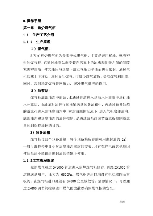
8.操作手册第一章焦炉煤气柜1.1生产工艺介绍1.1.1生产原理1)煤气柜:2万m3焦炉煤气柜为曼型干式煤气柜,主要是采用稀油、帆布密封的煤气柜,它通过油泵站向安装在活塞上的油槽和侧壁之间的间隙充满密封油,使其油压与活塞下部贮气压力平衡而进行密封,通过气柜活塞上下移动,及时吞吐煤气,可减少煤气放散,提高煤气利用率,同时,起到稳定煤气管网压力,缓冲煤气供应的作用。
2)油泵站:煤气柜底部油沟中的油、水通过管道进入到油水分离器中进行油水分离后,由油泵对油进行加压输送到预备油箱中,再通过预备油箱的溢流孔进入到活塞油沟中,密封油顺侧板流下,进入气柜底部油沟。
底部油沟和活塞油沟的油位控制,是通过油泵站调节溢流板控制溢流量达到保持油位的目的。
3)预备油箱煤气柜设四个预备油箱,每个预备箱所存的可用密封油约2m3,一般可维持停电8小时活塞油沟密封的需要。
只有在停电或其他原因使油泵站不能供给密封油的情况下使用。
1.1.2工艺流程叙述焦炉煤气通过DN1000管道进入焦炉煤气柜储存,再经DN1000管道输送到用户,压力为6500Pa。
煤气柜进出口均设有电动蝶阀及盲板阀。
在煤气柜进口处设有DN600安全放散管,紧急情况下,可以通过DN600调节阀控制进口煤气的放散以确保煤气柜的安全。
简图如下:1.2岗位操作规程1.2.1岗位工作任务1)严密监视和控制煤气柜的柜容量、活塞的倾斜度、活塞的运行速度、活塞油沟油位、底部油沟油位及水位、油泵站的启动频率等;2)密切联系煤气来源单位,煤气来源生产不正常时迅速采取措施并汇报上级领导;3)密切联系煤气用户,及时了解用户煤气用量和压力的变化;4)煤气柜的日常检查及维护。
1.2.2岗位管理范围1)焦炉煤气来源的稳定状况;2)焦炉煤气柜的柜容量控制及正常运行操作;3)焦炉煤气用户的用量及压力稳定状况;4)利用煤气柜的柜容量调控焦炉煤气平衡;5)煤气柜的正常检查及维护、柜区内的现场管理。
1.2.3岗位操作规程1.2.3.1开车(1)原始开车a)原始开车前置换作业准备工作①煤气管网置换合格,处于接收煤气状态;②2万m3焦炉煤气柜气密性试验、升降试验合格,辅助设施齐全,运行正常;③检查煤气管、氮气管、蒸汽管上各阀门的电动、手动控制系统灵活好使;④检查油泵站的油泵自动、手动操作灵活,并投入运行;⑤检查活塞油沟的油位是否在规定高度(990±35mm);⑥检查柜底油沟油位是否在规定高度(140±60mm)。
气柜操作手册
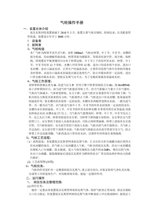
气柜操作手册一.装置总体介绍低压瓦斯回收装置始建于2010年5月。
装置主要气体压缩机、控制仪表、以及配套管件组成。
装置设计年开工8000小时。
1. 设备表2. 能耗表3:气柜构造本厂气柜为两塔节直升式气柜,容积5000m3。
气柜由钟罩、中Ⅰ节、中Ⅱ节、水槽四部分组成,均由钢板焊接而成,钟罩顶部为圆弧形。
顶部设有放空管、放空阀、取样阀,四周置有平衡重锤均匀分布于钟罩边缘,中Ⅰ节上下均有环形水封,钟罩、中Ⅰ节,中Ⅱ节均有12个导轮,水槽上环形导轨12根,进出口均设有两个水封,进出口水封槽,进出口溢流水封。
正常生产时溢流水封,主要作用是将气体中夹带的冷凝水及时排掉,由进出口溢流水封溢流出满足连续生产,防止冷凝水积存一定高度,进出口管会被冷凝水水封,使低压瓦斯气出不去,为了克服此现象而设溢流水封。
4:气柜工作原理:设钟罩和重锤总重为G,设进气压力P,作用于整个钟罩顶部的力为G1,则G1=PF=G。
加上对钟罩的浮力,故当进气时气柜能沿导轨上升。
但当气柜输入气量小于出气量时,气体内气体减少,气体密度降低,压力下降。
这时气柜在自重量作用下沿导轨下降,气柜内的压力恢复至原来的压力时,气柜就停止下降。
气柜进出口有水封槽,依靠溢流管的溢流作用,使水槽内的水保持一定的高度,水槽内有两根管道伸出水面。
一根为进气管,另一根为出气管。
向气柜送气前中Ⅰ节、中Ⅱ节的环形水封保持一定高度的水位,水槽内水位保持溢流。
中Ⅰ节、中Ⅱ节的环形水封和水槽.冬季采用常住水常溢流.用蒸加热保证水封.水槽水温5℃以上。
当气柜内气量增加时,钟罩、中Ⅰ节、中Ⅱ节先后上升,反之先后下降。
钟罩顶部设有安全罩,当钟罩下降到最小容积时,安全罩在出气管的管口上,安全罩的下部浸入水面形成水封,可防止将钟罩抽瘪,钟罩上部装有安全放空管,当气柜较低时,安全放空管的下部浸入水面,气柜内的气体不能排出,当气柜上升过高时,安全放空管下部离开水面,气柜内的气体能自动从放空管放空至大气,防止钟罩上升过高被顶翻。
煤气气柜运行操作(技术)规程范本

操作规程编号:LX-FS-A74008煤气气柜运行操作(技术)规程范本In The Daily Work Environment, The Operation Standards Are Restricted, And Relevant Personnel Are Required To Abide By The Corresponding Procedures And Codes Of Conduct, So That The Overall BehaviorCan Reach The Specified Standards编写:_________________________审批:_________________________时间:________年_____月_____日A4打印/ 新修订/ 完整/ 内容可编辑煤气气柜运行操作(技术)规程范本使用说明:本操作规程资料适用于日常工作环境中对既定操作标准、规范进行约束,并要求相关人员共同遵守对应的办事规程与行动准则,使整体行为或活动达到或超越规定的标准。
资料内容可按真实状况进行条款调整,套用时请仔细阅读。
1.气柜构造:本厂气柜为两塔节直升式气柜,容积10000m3。
气柜由钟罩、中Ⅰ节、中Ⅱ节、水槽四部分组成,均由钢板焊接而成,钟罩顶部为圆弧形。
顶部设有放空管、放空阀、取样阀,四周置有平衡重锤均匀分布于钟罩边缘,中Ⅰ节上下均有环形水封,钟罩、中Ⅰ节,中Ⅱ节均有14个导轮,水槽上环形导轨14根,进出口均设有两个水封,进出口水封槽,进出口溢流水封。
正常生产时溢流水封,主要作用是将气体中夹带的冷凝水及时排掉,由进出口溢流水封溢流出满足连续生产,防止冷凝水积存一定高度,进出口管会被冷凝水水封,使煤气出不去,为了克服此现象而设溢流水封。
2.气柜工作原理设钟罩和重锤总重为G,设进气压力P,作用于整个钟罩顶部的力为G1,则G1=PF=G。
加上对钟罩的浮力,故当进气时气柜能沿导轨上升。
三氯化硼气柜操作使用说明书
使用三氯化硼气柜的指南
三氯化硼气柜是化学实验室中常见的设备之一。
它能够保护实验人员不受有害气体的侵害。
但是使用时要特别小心,否则可能会有意外发生。
下面是操作使用说明书,希望能够帮到大家。
1. 准备工作
在使用三氯化硼气柜前,必须做好以下准备工作:
(1)检查气柜系统是否正常。
(2)确保通风系统处于开启状态。
(3)检查气柜内是否有防护手套、面罩等安全用具。
2. 操作步骤
(1)打开气柜前顶部折叠玻璃,仔细检查气柜内部是否有泄漏物质或其他异常情况。
(2)戴好防护手套、面罩等安全用具。
(3)将试剂瓶慢慢放入气柜中,注意不要碰撞或振动。
(4)在取出试剂前,必须等待试剂瓶中的气体被稀释到某个安全浓度,否则会发生严重的爆炸或着火事故。
(5)如果发现气柜出现异常,请及时关闭气柜并汇报相关工作人员。
3. 注意事项
(1)三氯化硼气柜不能用于高于10升的反应瓶中。
(2)气柜内瓶子数量需要适中,以便保持试剂瓶之间的距离,以增加安全性。
(3)操作时不要过于粗暴或慌乱,以免造成意外。
希望以上指南能够为您在操作三氯化硼气柜时提供帮助,对您的实验室安全保障做出积极的贡献。
NH3 VMB使用手册
NH3 VMB操作手册上海沅净电子工程技术有限公司O ri c lean Technology & Engineering Co., Ltd.PROPRIETARY NOTICE版权说明This document is the property of Oriclean Technology & Engineering Co., ltd. It is to be used by the customer for whose benefits this document is intended. Any data and drawings contained herein are strictly confidential and must not be copied, duplicated or reproduced in any way and disclosed to any third parties without prior permission by Oriclean Technology & Engineering Co., Ltd.此文件版权属上海沅净电子工程技术有限公司所有。
使用权限于此文件所适用的客户。
此文件所含的数据和图纸等未经上海沅净电子工程技术有限公司事先许可,不得拷贝、复制或以任何其他方式透漏给第三方。
目录一、警告 (4)1.特殊气体的危害 (4)2.危害警告与注意事项 (5)二、VMB概述 (7)1.本VMB的应用说明 (7)2.VMB作用 (7)3.VMB构造、大小 (7)4.VMB出厂标准说明 (7)5.盘面流程图 (8)三、VMB安装 (10)1.VMB使用环境要求 (10)2.VMB固定要求 (10)3.VMB Facility及连接要求 (10)4.注意 (11)四、一般VMB操作常识 (12)五、设备保养与维修 (12)1.VMB盘面 (12)2.VMB箱体 (12)3.检查对照表 (13)4.档案卡 (13)六、保固说明 (14)一、警告:1.特殊气体的危害:1)所有相关人员必须仔细阅读并了解使用气体的物质安全资料表(MSDS)。
KC-TECH气柜操作说明
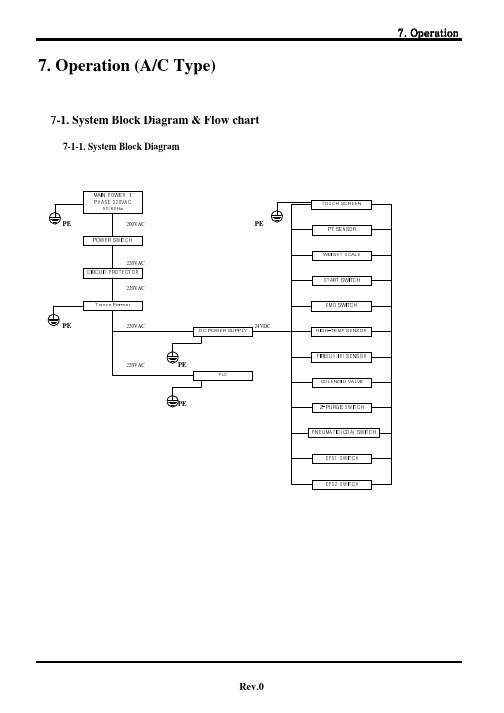
7. Operation (A/C Type)7-1. System Block Diagram & Flow chart 7-1-1. System Block Diagram7-4-2. Gas Supply<Fig. 7.4.2.1 Gas Supply>※ Notice : If you touch 'Cancel' button, message 'Touch 'Cancel' again' is shown.If you touch it again, screen is changed to main menu (before readiness).<Fig. 7.4.2.2 Gas Supply>■ Gas SupplyThis is menu screen for gas supply.Gas Supply : Mode to supply actual gas.Pipe Vacuum : Mode to check the degree of a vacuum of Process Line.Leakage Test : Mode to check manual decompression.pressurization.Pipe Cleaning : During gas supply, HPT1,MPT1,LPT1must be always vacuum. This is a mode to vent simply if there is under pressure.Please touch 'Gas Supply' if you want to proceed gas supply.Screen is changed to <Fig.7.4.2.4>.■ Gas SupplyWhen you touch 'Gas Supply', This screen is shown if HPT1,MPT1,LPT1 are higher than vacuum low limit of setting mode or weight value is less than 1st weight low limit of setting mode when there is weight option.Vacuum of HPT1,MPT1,LPT1 can be vented with the 'Pipe Vent' of Supply Menu.If there is, you think, filled gas in Cylinder, setting value for weight can be modified. If there is no filledgas, please replace Cylinder.<Fig. 7.4.2.3 Gas Supply><Fig. 7.4.2.4 Gas Supply><Fig. 7.4.2.5 Gas Supply>This screen is shown when you touch 'Cancel' on a selected mode among Supply Menu screen <Fig.7.4.2.1>.Screen differs per stage regarding Cylinder.Before Operation → change to Main Menu Purge Completed → change to Supply Menu 'Ready to Supply & Processor → change to Gas Supply■ Gas SupplyThis is screen for performing gas supply.Please close Regulator.If you touch 'Perform', then screen is changed to <Fig.7.4.2.5>.■ Gas SupplyThis is screen for performing gas supply.Please open the main valve of Cyliner.*If there is Valve Shutter(V/S) Option, open the valvemounting V/S in Cylinder. Refer to a separated V/Smanual for use.<Fig. 7.4.2.7 Gas Supply>■ Gas SupplyThis is screen for performing gas supply.Please control Regulator2.<Fig. 7.4.2.10 Gas Supply><Fig. 7.4.2.11 Gas Supply>■ Gas SupplyThis is screen for performing gas supply.Gas is supplied as LPI1 Valve is opened.Notice : Make sure that PMV1 Valve must be opened before gas supply. A man in charge of equipment operation has to check whether PMV1 Valve is Open in the above mode.■ Gas Supply -> PauseThis is screen for performing gas supply.If you touch 'Pause', then screen is changed to <Fig.7.4.2.12> and pause is performed.<Fig. 7.4.2.12 Gas Supply> <Fig. 7.4.2.13 Gas Supply> <Fig. 7.4.2.14 Gas Supply>This is screen for performing Pause.Password should be checked before performing'Pause'. Please enter 4 digit of registered password. If password is right, screenis changed to<Fig.7.4.2.13>.Users be careful of pasword sequrity.■ Gas Supply -> PauseThis is screen for performing Pause.If you touch 'Perform', then screen is changed to<Fig.7.4.2.14>.■ Gas Supply -> PauseThis is screen for performing Pause.If you touch 'gas supply' re-supply can be made (there is no interlock such as 'gas supply impossible').If you touch 'gas supply' soon after you touch a partother than 'gas supply', re-supply CANNOT be made(there is INTERLOCK such as 'gas supply impossible').*Users be careful.<Fig. 7.4.2.15 Gas Supply><Fig. 7.4.2.16 Gas Supply><Fig. 7.4.2.17 Gas Supply>This is screen for performing gas supply.If you touch 'Perform', then gas is supplied immediately.■ Gas Supply -> StopThis is screen for performing gas supply.If you touch 'Stop', then screen is changed to <Fig.7.4.2.17> and Stop supplying is performed.■Gas Supply -> StopThis is screen for performing 'Stop".Password should be checked before performing 'Stop'.Please enter 4 digit of registered password.If password is right, screenis changed to <Fig.7.4.2.18>.Users be careful of pasword sequrity.<Fig. 7.4.2.18 Gas Supply><Fig. 7.4.2.19 Gas Supply>This is screen for performing 'Stop".If you touch 'Perform', then supply is stopped andscreen is changed to initil mode <Fig.7.4.2.19>.■ Gas Supply -> StopThis is screen for performing 'Supply Stop".It is changed to 'Before Operation'.<Fig. 7.4.2.20 Gas Supply><Fig. 7.4.2.21 Gas Supply><Fig. 7.4.2.22 Gas Supply>This is screen for Alarm during gas supply.This alarm occurs when pressure becomes lower than HPT1 1st low limit and the state continues for 3seconds.Notice : If the alarm condition is cancelled, Alarm Pop-up window disappears.■ Gas Supply -> AlarmThis is screen for Alarm during gas supply.This alarm occurs when pressure becomes lower than HPT1 2nd low limit and the state continues for 3seconds.This alarm occurs when B-Cylinder is not 'ready tosupply'.* Notice *'Auto change' is made when B-Cylinder is 'ready to supply'.■ Gas Supply -> AlarmThis is screen for Alarm during gas supply.This alarm occurs when weight becomes lower than Weight-A 1st low limit and the state continues for 3seconds.<Fig. 7.4.2.23 Gas Supply><Fig. 7.4.2.24 Gas Supply><Fig. 7.4.2.25 Gas Supply>This is screen for Alarm during gas supply.This alarm occurs when weight becomes lower than Weight-A 2nd low limit and the state continues for 3seconds.This alarm occurs when B-Cylinder is not 'ready to supply'.* Notice *'Auto change' is made when B-Cylinder is 'ready to supply'.■ Gas Supply -> AlarmThis is screen for Alarm during gas supply.This is screen for performing 'High Pressure Purge'.GNBV->LPV1 Valve is opened.■ Gas Supply -> AlarmThis is screen for Alarm during gas supply.This alarm occurs when pressure of LPT1 becomes higher than high limit of L/FPT1.In this case, gas supply is stopped and high pressure purge is performed.Notice : Please close Regurator before performing highpressure purge.<Fig. 7.4.2.26 Gas Supply><Fig. 7.4.2.27 Gas Supply><Fig. 7.4.2.28 Gas Supply>This is screen for performimg 'High Pressure Purge'.If you touch 'gas supply' re-supply can be made (there is no interlock such as 'gas supply impossible').If you touch 'gas supply' soon after you touch a part other than 'gas supply', re-supply CANNOT be made (there is INTERLOCK such as 'gas supply impossible').*Users be careful.■ Gas Supply -> AlarmThis is screen for Alarm during gas supply.This alarm occurs at the following condition :L/FPT1 2nd low limit < LPT1 Value < L/FPT1 1st low limit.Please set supplied pressure controlling Regurator. If supplied pressure setting is impossible, please check primary (HPT1) pressure.■ Gas Supply -> AlarmThis is screen for performimg 'gas supply'.If you touch 'Perform', process is made up to 'Control the Regurator 2'.For next stage, it is identical from <Fig.7.4.2.8>.<Fig. 7.4.2.29 Gas Supply><Fig. 7.4.2.30 Gas Supply><Fig. 7.4.2.31 Gas Supply>This is screen for Alarm during gas supply.This alarm occurs when pressure of LPT becomes lower than low limit of L/FPT1 2nd low limit.This alarm occurs when B-Cylinder is NOT 'ready to supply' (Auto Change fuction available per option->L/FPT1 Auto Chan)* Notice *'Auto change' is made when B-Cylinder is 'ready to supply'.■ Gas Supply -> AlarmThis is screen for Alarm during gas supply.This alarm occurs when pressure becomes lower than low limit of MPT1.Please control Regulator1.Notice : If the alarm condition is cancelled, AlarmPop-up window disappears.■Gas Supply -> AlarmThis is screen for Alarm during gas supply.This alarm occurs when pressure becomes higher than high limit of MPT.Please control Regulator1.Notice : If the alarm condition is cancelled, Alarm Pop-up window disappears.<Fig. 7.4.2.32 Gas Supply>This is screen for Alarm during gas supply.This alarm occurs when pressure becomes higher than set point of HPT1 High Alarm(These are all checked after being ready to supply,process).Jacket power is shut off because heat is, you think,over.Notice : If the alarm condition is cancelled, Alarm Pop-up window disappears.7-4. Auto Processing7-4-1. Procedure of Auto Processing< Fig. 7.4.1.1 Pipe Cleaning prior to Replacement > < Fig. 7.4.1.2 Pipe Cleaning prior to Replacement > < Fig. 7.4.1.3 Pipe Cleaning prior to Replacement >■ Initial menuThis is the stage to clean pipes prior to cylinder change.Select A or B at this initail menu. Then this can be changed to screen <Fig.7.4.1.2>.■ Main menuAuto Processing : Auto mode to replacecylinder.Pipe Cleaning : Mode to perform manualpurge.Leakage Test : Mode to check manualreduction.pressurizing.Manul Operation : Mode to open/close anyrequired valve.Please touch 'auto performing' on the screen if cylinder replacement is required.Select auto processing. Then this can be changed to screen <Fig. 7.4.1.3>.■ Auto processingThis message is to check whether cylinder is open or closed. Please touch 'perform' after checking cylinder. If Toxic is selected in the options, please check pressure of HPT1,MPT1,LPT1. If it is above '0', itbecomes like screen <Fig.7.4.1.4>< Fig. 7.4.1.4 Pipe Cleaning prior to Replacement >< Fig. 7.4.1.5 Pipe Cleaning prior to Replacement >※ Notice1. Pipe Vacuum Failure : This is an error caused when vacuum of VPT is higher thanlow limit set point of vacuum as valve GNBV opens.2. Pipe Line Failure : This is an error caused when vacuum of HPT1,MPT1,LPT1 is higher than low limit set point of vacuum as VPT becomes vacuum and valves LPV1, HPI1 open.3.Purge-N2 Supply Failure : This is an error caused when supply from HPT1 to Purge-N2 is less than low limit set point of Purge-N2Please touch 'perform' in the 'existing gas found inside pipes'. Then Pulse Vent Sequence is precessed.If pressure of HPT1,MPT1,LPT1 becomes below '0'during Pulse Vent, first pipe cleaning is performed prior to regular replacement.*Pulse Vent : This is to vent a little bit of actual gas existing at HPT1,MPT1,LPT1.■ Auto processingThis screen is for first vent cleaning prior to replacement.Performing is done until set number. 2nd purge count in set mode is done like 2nd purge (GNBV->LPV1->HPI1), the remaining is done like 1st purge(GNBV->HPV1).After completed, it is changed to decompression test prior to replacement.<Fig.7.4.1.6>*If an error such as notice occurs, touch 'perform'.Then performing is done again.< Fig. 7.4.1.6 Decompression Test prior to Replacement >※ Notice1. Decompression Test Failure : This is an error caused when pipe vacuum failure orpipe line failure occur and when the difference between first value and current value is more than leakage pressure conversion value during decompression test.< Fig. 7.4.1.7 Pipe Cleaning prior to Replacement >This is screen for decompression test prior to replacement.Please perform decompression test dring set time after 1 minute of PT sensor stabilization time passes as HPT1,MPT1,LPT1 become vacuum.If completed, it is changed to 2nd pipe cleaning prior to replacement.<Fig.7.4.1.7>*If an error such as notice occurs, touch 'perform'.Then performing is done again.■ Auto processingThis is screen for decompression test prior to replacement.Please perform decompression test dring set time after 1 minute of PT sensor stabilization time passes as HPT,MPT,LPT become vacuum.If completed, it is changed to 2nd pipe cleaning prior to replacement.<Fig.7.4.1.7>*If an error such as notice occurs, touch 'perform'.Then performing is done again.< Fig. 7.4.1.8 Cylinder replacement >< Fig. 7.4.1.9 Pipe Cleaning after Replacement >< Fig. 7.4.1.10 Pressurizing Test after Replacement >■ Auto processingThis is screen for 1st pipe cleaning after replacement.Number of pipe cleaning after replacement is as per set number like 1st purge (GNBV->HPV1).If completed, it is changed to pressurization test after replacement.<Fig.7.4.1.10>Please touch 'cancel'. Then screen is returned to cylinder replacement screen. <Fig.7.4.1.8>■ Auto processingThis is screen for pressurization test after replacement.After pressurizing HPT1, please perform pressurizing test dring set time after sensor stabilization PT sensor.If completed, it is changed to 2nd Vent Cleaning after replacement. <Fig.7.4.1.11>Please touch 'cancel'. Then screen is returned to cylinder replacement screen. <Fig.7.4.1.8>*If an error such as notice occurs, touch 'perform'.Then performing is done again.※ Notice1.High Pressure Gas Deficient : Error that occurs when pressure of HPT is less thanlow limit of leak check pressure in setting2.Pressurizing Test Failure : Error that occurs when pressure of HPT is less thanlow limit of leak check pressure during stabilization time and when the difference between first value and current value is more than leakage pressure conversion value during pressirizing test.< Fig. 7.4.1.11 Pipe Cleaning after Replacement >■ Auto processingThis is screen for 2nd pipe cleaning after replacement.Procedure is the same as that of 1st pipe cleaning prior to replacement.If completed, it is changed to mode for gas supply.<Fig.7.4.1.12>Please touch 'cancel'. Then screen is returned to cylinder replacement screen.<Fig.7.4.1.8>7-1-2. Flow Chart7-2. Main Menu< Fig. 7.2.1 Initial screen >※ Notice : In case power is off/on during gas is supplied, instant power off screen is showninstead of password entering screen.< Fig. 7.2.2 Password entering screen for stopping gas supply >※ Notice : Make sure that users must register the password for stopping.■Password entering screen for stopping gas supplyThis password entering screen is for stopping gas supply or a momentary pause.Way of entering is the same as entering password.If you cancel numerinc pad or touch the return-shaped area, the screen can be returned to password entering screen.<Fig.7.2.1>Maximum 4 (four) digit can be registered.On this screen, there is also a password registered for option set up.■ Initial ScreenThis screen is shown when the connection with main controller PLC is made after switch is on.If you touch key-shaped area, then number pad is pop-up. And if you enter the password that was already registered, then you can get the right to control the system.If you wrongly enter the password, there is no error messege aroused. You can just enter again on the existing screen.There are two type of password ; one is for system administration, and the other is for stopping gas supply.< Fig. 7.2.3 Initial menu >7-3. Sub menu< Fig. 7.3 Sub menu >■ Initial screenThis is for intial screen for gas supply work.If you select A/B on the above menu, cylinder changeand gas supply can be performed.Before working gas supply, please enter setup value for gas supply on the sub menu.If you touch ‘SUB MENU’on the above screen, screen is changed to <Fig. 7.3> screen.■Sub menuThis screen is for sub menu.If you touch ‘CONFIG-A’on the above menu, screenis changed to <Fig.7.3.1.1> screen.7-3-1. Setting mode-A※ Notice : Safe operation of Gas Cabinet can be assured when the operator in charge correctlyenter all the setup. It is recommended that the operator in charge should enter setup value for each item on setup mode under the supervision of a manager.We strongly recommend that setup results for each item should be cross-checked with users before gas supply.< Fig. 7.3.1.1 Setup mode-A >5LPT,FPT LowLow LimitsIf pressure of subsidiary (2nd) Regurator goes down under set point during gas supply, message ‘LPT(FPT) 2nd low pressure’ is shown and alarm occurs.** Setting range : -15.0~999.9 PsiIf LPT,FPT Auto Change is selected in the option, it is automatically change.3HPT High Alarm ValueThis is an item to check the high pressure of primary (1st) cylinder due to overheating at the application of Jacket Heater. If pressure of HPT goes up over set point during gas supply, message ‘HPT high Alarm occured/Jacket Down → necesary action require ** Setting range : -15~9999 Psi4LPT,FPT Low LimitsIf pressure of subsidiary (2nd) Regurator goes down under set point during gas supply, message ‘LPT(FPT) 1st low pressure/operate Regurator’ is shown and alarm occurs.** Setting range : -15.0~999.9 PsiNO.ITEMDESCRIPTIONIf pressure of HPT goes down under set point during gas supply, itautomatically switch over to the cylinder of the other side that is on stand-by. In this case, message ‘auto switch over completed’ is shown and alarm occurs.If the other side cylinder is not on stand-by, there is an alarm "HPT delivery pressure status/auto switch over impossible" and alarm occurs.** Setting range : -15~9999 PsiHPT LowLow Limits21HPT Low LimitsIf pressure of HPT goes down under set point during gas supply, message ‘HPT 1st low pressure’ is shown and alarm occurs.** Setting range : -15~9999 Psi■ setup mode-AThis screen is for 'Setup mode A’.This is a mode where parameter value to be entered at the time of gas supply work and many of parameter value to be entered at the time of auto work are set up.Description for setup of each parameter can be found at the next chapter.(Explanation is focused on users)2'nd Purge count This item counts purge number from Regurator to Valve3 during 1st,2nd purge before change. That number must not exceeed 1st,2nd count before change.** Setting range : 3~9999 count9Wight Tare This item is used when work is done with actual gas weight that is gross cylinder weight minus vacuum cylinder weight. Please enter the value that is taken filled gas weight away from the shown value.10NPT Alarm Value If pressure of MPT goes up over set point during gas supply, message ‘MPT Alarm occured/check pipe’ is shown and alarm occurs.This is for By-Pass Check between valve PGII and PGI during gas supply. ** Setting range : -15~9999 Psi12Pulse Vent Time If pressure is under "0" Psi by set time at the sequence that vents actual gas a bit, message 'pipe vacuum state bad'is shown and alarm occurs. This item is applied when alarm 'existing gas found in the pipe' occurs.** Setting range : 0~9999 minutes7Wight Low Limits If weight of W/S goes down under set point during gas supply, message 'Weight 1st Warning' is shown and alarm occurs.** Setting range : 0.0~999.9㎏8Wight LowLow Limits If weight of W/S goes down under set point during gas supply, it is automatically changed to the cylinder of the other side that is ready to be supplied. In this case, message ‘auto change completed’ is shown and alarm occurs.If the other side cylinder is not on stand-by, there is an alarm "Weight 2nd warning /auto switch over impossible" and alarm occurs.** Setting range : 0.0~999.9㎏11If pressure of subsidiary (2nd) Regurator goes up over set point during gassupply, message ‘LPT(FPT) high pressure/press cancel key’ is shown andalarm occurs.If LPT value goes up over set point, gas supply is stopped and if "Cancel" keyis pressed, high pressure purge operates. FPT makes warning alarm only. (Nostoppage of gas supply)** Setting range : -15~9999 PsiLPT,FPT High Limits6Sensor Sablizing TimeThis is time setting for PT Sensor stabilizing after pressurizing using L/C He Gas during pressurizing test.** Setting range : -15~9999※ Notice : In case pressure of L/C He Gas goes up over 1000 psi, please set time for stabilization over 30 minutes at le7+ Leak Check TimeThis is time setting for checking whether pipe line is all right without leakage after cylinder change or pipe part change.** Setting range : 0~99998- Leka Check TimeThis is time setting for check whether main valve of cylinder is rightly closed.** Setting range : 0~999912Leak Check TOL'This is setting mode for allowed leak rate at the time of leak check work.** Setting range : 0~9999 psi※ Notice : In case that pressure of the L/C He Gas increase more than 1000psi, please set up time as more than 30minutes at least.9Purge-N2 LimitsIf pressure of N2 at the time of purge process goes down under set point, message 'Nitrogen Supply Failure' is shown and alarm occurs.** Setting range : -15~9999 Psi10Pulse Vent TimeIf pressure is not under "0" Psi by set time at the sequence that vents actual gas a bit,message 'pipe vacuum state bad' is shown and alarm occurs. This item is applied when alarm 'existing gas found in the pipe' occurs.** Setting range : 0~9999 minutes115Leka Check LimitsThis is setting mode for checking whether main valve of cylinder is well closed and CGA Connector is well connected. If HPT value goes down under set point at the time of processing positive L/C, message 'Pressurizing Test Problem' is shown and alarm occurs.** Setting range : -15~9999 Psi6Vacuum LimitsIf VPT value goes up over set point at the time of purge process after setting up vacuum limit value of pipe line, message 'pipe Line Vacuum Problem' is shown and alarm occurs.** Setting range : -15~99 Psi3Post-Purge 1'st This is mode for setting up purge count ro remove particles inside the pipe after cylinder change. Please set purge process considering the type of used gas.** Setting range : 10~99994Post-Purge 2'ndNO.ITEMDESCRIPTION1Pre-Purge 1'st This is mode for setting up purge count ro remove the existing gas before cylinder change. Please set purge process considering the type of used gas.** Setting range : 10~9999※ Notice : In case of corrosive gas, minimum 150 counts should be set.2Pre-Purge 2'nd< Fig. 7.3.1.2 Setting mode-A >< Fig. 7.3.1.3 Setting mode-A >< Fig. 7.3.1.4 Setting mode-HEATER >■ Setting mode-AEntering password is required before mode setting.Ther is no message when pasword is wrongly entered.Just enter again.It is changed to screen <Fig.7.3.1.4> when the password for setting Controller Type is entered.Notice : Only registered passwords are allowed to be used.Users be careful of password security.■ Setting mode-AIf entered password is correct, the indicated part of the above screen is 'flickering'.Notice : Only registered passwords are allowed to be used.Users be careful of password security.This can be changed to screen <Fig.7.3.1.4> when youtouch the key 'heater configration'.■Setting mode-HEATERThis screen is for 'Setup mode HATER’.This is a mode where parameter value to be entered at the time of heating.Description for setup of each parameter can be found at the next chapter.(Explanation is focused on users)NO.ITEMDESCRIPTIONLine Heater B Set Point Set up the set point temperature of the Line Heater B.3Line Heater A High Alarm Set up the temperatue for High temperature Alarm of the Line Heater A.41Line Heater A Set PointSet up the set point temperature of the Line Heater A.2Line Heater A Low Alarm Set up the temperature for Low temperature Alarm of the Line Heater A.Set up the temperature for Low Temperaure Alarm of Overheat Sensor in the Heating Block.1210Block Over Heater Set Set up the set point temperature of Overheat Sensor in the Heating Block.5Line Heater B Low Alarm Set up the temperature for Low temperature Alarm of the Line Heater B.6Line Heater B High Alarm Set up the temperatue for High temperature Alarm of the Line Heater B.7Block Heater Set Point Set up the set point temperature of the Heating Block.8Block Heater Low Alarm Set up the temperature for Low temperature Alarm of the Heating Block.13Low Alarm Delay TimeSet up the Delay time for Check of Alarm of low temperature after running Line Heating & Heating Block.9Block Heater High Alarm Set up the temperature for High temperature Alarm of the Heating Block.Block Over Heater HighSet up the temperature for High Temperaure Alarm of Overheat Sensor in the Heating Block.11Block Over Heater Low< Fig. 7.3.1.5 Controller Type Setting >< Fig. 7.3.1.6 towards Time Setting >< Fig. 7.3.1.7 Equipment Number Entering >■ Towards Time SettingSetting can be corrected after entering password.Setting enough time for valves related to items guarantees seamless use.Notice : Initial setting has been made by manufacturer.Before change, checking is required at the manual operaton.■ Entering Equipment NumberThis is screen for entering equpment number.8 (eight) digit English alphabet, numbers can be entered.7-3-2. Calibration Mode< Fig. 7.3.2.1 Calibration mode >< Fig. 7.3.2.2 Calibration mode >< Fig. 7.3.2.3 Calibration mode >■ Calibration modeThe above is PT & Weight scale calibration mode.If you touch 'Calibration mode A' on the screen, this is changed to screen <Fig 7.3.2.2>.Notice : Calibration mode can not be performed at the supply preparation or gas supply.■ Calibration modeScreen can be changed to calibration mode after entering password. Please enter the registered 4 digit password.Notice : Only registered passwords are allowed to be used.Users be careful of password security.■ Calibration modeThis is the screen prior to performing calibration mode.Performing : Performing Calibration Cancelling : Cancelling CalibrationPressure Calibration : Full range setting of PT & W/S and entering Offset value.Screen is changed to screen <Fig 7.3.2.4> when you touch 'Pressure Calibration'.Notice : After completion of G/C installation and Utility Line, sensor should be calibrated after settingfull range of PT & W/S.< Fig. 7.3.2.4 Calibration mode >< Fig. 7.3.2.5 Calibration mode >< Fig. 7.3.2.6 Calibration mode >■ Calibration modeThis is the screen for entering maximum value of PT &W/S before sensor calibration. Please enter full range of PT & W/S.Screen is changed to calibration mode when you touch'cancel' after enering.■Calibration modeCalibration can be performed when you touch 'perform'on the above screen.Notice : Sequence for making air pressure is performedwhen you perform calibation mode.■Calibration modeThis is screen for performing calibation mode.。
气柜操作规程
目录前言 (3)第一章低压瓦斯回收装置 (4)第一节装置介绍 (4)第二节工艺流程简述及工艺流程图 (4)第三节气柜 (8)第四节气柜的投用调试 (12)第五节气柜的柜容报警及联锁控制 (16)第六节螺杆压缩机 (16)第七节主要设备及技术指标 (19)第八节工艺控制卡片 (23)第二章装置开工操作规程 (27)第一节装置全面大检查 (27)第二节压缩机系统的清洗及冷却柴油系统的水清洗 (28)第三节装置的吹扫 (30)第四节气柜的升降、气密试验及置换 (30)第五节鼓风机单机运转操作规程 (32)第六节螺杆压缩机单机试运转 (34)第七节气柜系统的开工 (36)第三章装置停工及气柜维护 (41)第一节装置停工 (41)第二节装置维护与维修 (43)第四章装置事故处理预案 (47)第一节气柜瓦斯系统泄漏事故预案 (47)第二节压缩机爆缸事故预案 (48)第三节气柜区域着火爆炸事故处理方案 (49)第四节停电事故预案 (50)第五章岗位操作法 (51)第一节水封罐操作 (51)第二节分液罐操作 (51)第三节污水系统操作 (51)第四节柴油系统操作 (51)第五节气柜系统操作 (51)第六章安全与职业健康操作规程 (53)第一节防止人身中毒 (53)第二节防止火灾爆炸 (54)第三节气柜装置安全规则 (56)第四节气柜装置装置安全操作要求 (57)第五节气柜装置开工安全规定 (59)第七节气柜装置停工安全规定 (60)第八节气柜装置检修安全规定 (61)第九节气柜装置冬季作业安全规定 (63)第十节塔、柜类设备安全规程 (64)第十一节主要消防、气防器材使用须知 (64)第十二节气柜装置安全防护规定 (69)第十三节防火防爆规定 (70)第十四节装置事故处理预案 (71)第十五节安全常识 (72)附录 (77)前言低压瓦斯回收装置主要由5000m³卷帘式橡胶膜干式气柜、螺杆压缩机等设施组成。
煤气柜进出口切断阀自动开关及手动开关说明

煤气柜进出口切断阀自动开关及手动开关说明1.气柜进口切断阀自动开关条件:气柜高度联锁投入时,气柜高度二选二大于95%,该阀门自动全关。
2.气柜进口切断阀DCS开关,在DCS画面阀门上有开关,点击阀门后,可选择是否进行操作,与其它接入DCS的阀门操作一致。
3.气柜进口切断阀现场手动开关方法1:当因为失电或工况异常时,可采取到现场开关阀门,首先要关闭仪表气源并泄尽阀门气室内仪表气压力,阀门上部有一红色旋转开关(现场不控制时该旋转开关处于打开状态),现场需手动关闭阀门时,先顺时针旋转红色开关至全关状态,后压动液压杠杆,使阀门气室进气,推动阀杆旋转,阀门逐渐全关。
4.气柜进口切断阀现场手动开关方法2:此方法必须保证仪表气源压力0.4MPa以上,在电磁阀接线盒旁边有一电磁阀手动/自动切换旋钮(阀门需要自动控制时打在A位置),用小改刀旋转使其在W位置时,阀门气室进气,推动阀杆旋转,阀门逐渐全关。
5.气柜出口切断阀自动开关条件:气柜高度联锁投入时,气柜高度二选二大于15%,该阀门自动全关。
6.气柜进口切断阀DCS开关,在DCS画面阀门上有开关,点击阀门后,可选择是否进行操作,与其它接入DCS的阀门操作一致。
7.气柜出口切断阀现场手动开关方法1:当因为失电或工况异常时,可采取到现场关阀门,首先要关闭仪表气源并泄尽阀门气室内仪表气压力,阀门气缸上部有一红色手轮,上面有开关方向标识open/close,现场需手动关闭阀门时,按关闭方向,扳动手轮使阀门逐渐关闭。
由于阀门处于常开状态,管道内介质杂质较多,有可能粘接阀板,关闭时较为费力。
8.气柜进口切断阀现场手动开关方法2:此方法必须保证仪表气源压力0.4MPa以上,在电磁阀接线盒旁边有一电磁阀手动/自动切换旋钮(阀门需要自动控制时打在A位置),用小改刀旋转使其在W位置时,阀门气室进气,推动阀杆旋转,阀门逐渐全关。
- 1、下载文档前请自行甄别文档内容的完整性,平台不提供额外的编辑、内容补充、找答案等附加服务。
- 2、"仅部分预览"的文档,不可在线预览部分如存在完整性等问题,可反馈申请退款(可完整预览的文档不适用该条件!)。
- 3、如文档侵犯您的权益,请联系客服反馈,我们会尽快为您处理(人工客服工作时间:9:00-18:30)。
自 动 气 柜操 作 手 册目录一 、 界 面 介 绍 ................................................................................................... 1 二 、 操 作 权 限 获 取 与 取 消 ........................................................................... 3 三 、 参 数 设 置 ................................................................................................... 5 四 、 PT 传 感 器 自 动 校 零 ( 以 左 操 作 为 例 ) ...................................... 10 五 、 手 动 操 作 ( 以 左 操 作 为 例 ) ........................................................... 14 六 、 吹 扫 操 作 ( 以 左 操 作 为 例 ) ........................................................... 16 6.1 泄 压 ..................................................................................................... 17 6.2 第 一 次 吹 扫 ....................................................................................... 19 6.3 负 保 压 ................................................................................................ 21 6.4 第 二 次 吹 扫 ....................................................................................... 23 6.5 换 瓶 ..................................................................................................... 24 6.6 第 三 次 吹 扫 ....................................................................................... 26 6.7 正 保 压 ................................................................................................ 27 6.8 第 四 次 吹 扫 ....................................................................................... 30 6.9 吹 扫 完 成 ........................................................................................... 31 6.10 供 气 准 备 ......................................................................................... 33 6.11 供 气 ................................................................................................... 35 七 、 系 统 设 置 ................................................................................................. 36 八 、 报 警 系 统 ................................................................................................. 38-1-一、界面介绍SIH4 气 柜 与 NH3 气 柜 相 比 ,增 加 了 高 压 保 压 ,减 少 了 管 线 伴 热 和 钢 瓶 加 热 、 钢 瓶 称 重 功 能 , 其 他 操 作 一 致 。
这 里 以 NH3 气 柜操作为例。
系统启动后,自动进入主界面,如下图如上图, 1、 通讯状态指示。
闪烁表明人机交互正常, 如果一直不显示 或者 一 直 显 示 ,表 明 通 讯 暂 时 中 断 ,此 时 操 作 无 反 应 ,一 般 等 待 一 段时间即可恢复。
2、 阀 门 状 态 指 示 。
红 色 表 示 阀 门 开 , 绿 色 表 示 阀 门 关 。
3、 加 热 状 态 指 示 。
文 字 红 色 表 示 加 热 已 启 动 , 文 字 白 色 表 示 加 热已关闭。
-1-4、 阀 门 类 型 指 示 。
灰 色 表 示 手 动 阀 门 , 不 能 指 示 开 关 状 态 。
5、 加 热 控 制 器 状 态 指 示 。
红 色 表 示 加 热 带 通 电 , 黑 色 表 示 加 热 带断电。
( 仅 限 于 NH3 气 柜 ) 6、 左 右 管 路 工 作 状 态 。
分 为 4 种 : 未 吹 扫 、 已 吹 扫 、 备 用 、 使 用中。
7、 工 作 管 路 指 示 。
分 为 主 画 面 、 左 操 作 、 右 操 作 、 吹 扫 完 成 。
8、 操 作 区 。
可 以 执 行 操 作 的 区 域 。
-2-二、操作权限获取与取消为了防止操作人员误操作和无关人员操作,系统的操作需 要获取相应的权限。
当没有获取权限时, 在选择功能进行操作时系统会弹出口令 窗 ,只 有 输 入 正 确 的 用 户 名 和 密 码 ,确 认 后 才 能 获 取 对 应 等 级 的 权限。
操 作 完 成 后 ,权 限 会 保 持 一 定 的 时 间 ,为 了 防 止 这 段 时 间 内 无操作或无关人员操作, 可 以 点 击 右 下 角 的 “退 出 登 录 ”来 取 消 权 限。
用 户 名 、 密 码 可 以 修 改 、 删 除 、 增 加 。
选 择 主 画 面 上 的 “系 统 设 置 ”, 然 后 选 择 “用 户 管 理 ”即 可 进 入 功 能 窗 口 。
-3-点击已经存在的用户名或口令等, 就可在弹出的窗口中修改 用 户 名 、口 令 、组 别 和 注 销 时 间 ,在 空 白 行 或 新 建 行 可 以 新 增 用 户 。
不 过 , 用 户 名 为 “Admin” 和 “PLC User” 的 用 户 名 、 组 别 不 能 修 改 ,高 等 级 权 限 可 以 修 改 、删 除 、新 增 同 等 级 和 低 等 级 权 限 的 用户,不能查看更高等级用户的用户名等信息。
注意: 1、 口 令 的 最 小 长 度 是 4 个 字 符 2、 注 销 时 间 表 示 用 户 获 取 权 限 后 如 果 在 设 定 的 时 间 ( 单 位 : 分 钟)没有执行任何操作,则权限自动取消。
3、 组 别 的 高 低 : 车 间 >组 长 >操 作 员 。
-4-三、参数设置设置正确的参数是系统正常工作的前提和保证。
请务必了解 每个参数的意义和设置方法,避免不恰当的参数导致的系统停 机。
如 果 界 面 中 有 “参 数 设 置 ”按 钮 , 点击即可进入参数设置界面, 如下图:泄压次数:执行泄压过程中脉冲泄压的次数。
前吹扫次数:第一次吹扫和第二次吹扫时执行的次数。
低 压 段 吹 扫 次 数 :第 一 次 吹 扫 过 程 中 执 行 低 压 段 吹 扫 的 次 数 。
总 次数不能操作前吹扫次数,差值为高压段吹扫次数。
后吹扫次数:第三次吹扫和第四次吹扫时执行的次数。
负保压时间:执行负保压过程中保压的时间。
正保压时间:执行正保压过程中保压的时间。
正保压稳压时间:执行正保压前等待压力稳定的时间。
-5-抽真空压力: 抽除管道中气体时只有当压力低于该值才认为抽除 合 格 , 否 则 提 示 “抽 真 空 压 力 不 足 ”的 报 警 。
向 管 道 中 充 入 N2 时 只 有 当 压 力 高 于 该 值 才 认 为 充 吹 扫 N2 压 力 : 气 合 格 , 否 则 提 示 “吹 扫 N2 压 力 不 足 ”的 报 警 。
正保压压力下限:正保压稳压时间结束后对保压压力进行判断, 如果压力低于该设定值则不允许进行正保压测试,并提 示“保压压力不足”的报警。
负保压允许偏差:负保压时间到后允许压力升高的幅度。
正保压允许偏差:正保压时间到后允许压力下降的幅度。
空 瓶 报 警 压 力 :高 压 段 压 力 低 于 该 值 时 系 统 报 警 ,提 醒 操 作 人 员 注意空瓶切换。
左右侧都适用。
空 瓶 切 换 压 力 :高 压 段 压 力 低 于 该 值 时 如 果 满 足 切 换 条 件 ,则 完 成切换,如果不满足切换条件,则继续使用。
自动切换 的 条 件 : 一 侧 处 于 “使 用 中 ”且 发 生 空 瓶 切 换 压 力 报 警 ; 另 一 侧 处 于 “备 用 ”。
左 侧 空 瓶 报 警 重 量 :左 侧 钢 瓶 重 量 低 于 该 值 时 系 统 报 警 ,提 醒 操 作人员注意空瓶切换。
( 仅 限 于 NH3 气 柜 ) 左侧空瓶切换重量:左侧空瓶重量低于该值时如果满足切换条 件,则完成切换,如果不满足切换条件,则继续使用。
( 仅 限 于 NH3 气 柜 ) 右 侧 空 瓶 报 警 重 量 :右 侧 钢 瓶 重 量 低 于 该 值 时 系 统 报 警 ,提 醒 操 作人员注意空瓶切换。
( 仅 限 于 NH3 气 柜 ) 右侧空瓶切换重量:右侧空瓶重量低于该值时如果满足切换条-6-件,则完成切换,如果不满足切换条件,则继续使用。