Hp交换机操作手册中文版
HPE N3200 交换机系列说明书
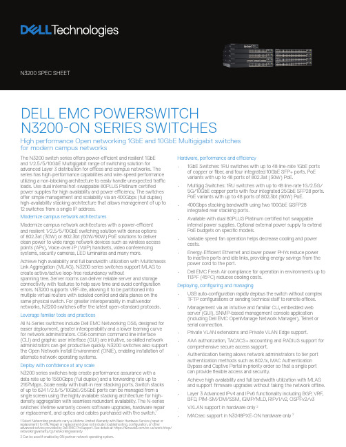
The N3200 switch series offers power-efficient and resilient 1GbEand 1/2.5/5/10GbE Multigigabit range of switching solution for advanced Layer 3 distribution for offices and campus networks. The series has high-performance capabilities and wire-speed performance utilizing a non-blocking architecture to easily handle unexpected traffic loads. Use dual internal hot-swappable 80PLUS Platinum certified power supplies for high availability and power efficiency. The switches offer simple management and scalability via an 400Gbps (full duplex) high-availability stacking architecture that allows management of up to 12 switches from a single IP address.Modernize campus network architecturesModernize campus network architectures with a power-efficientand resilient 1/2.5/5/10GbE switching solution with dense optionsof 802.3at (30W) or 802.3bt (60W/90W) PoE solutions to deliver clean power to wide range network devices such as wireless access points (APs), Voice-over-IP (VoIP) handsets, video conferencing systems, security cameras, LED luminaires and many more.Achieve high availability and full bandwidth utilization with Multichassis Link Aggregation (MLAG). N3200 series switches support MLAG to create active/active loop-free redundancy withoutspanning tree. Server rooms can deliver reliable server and storage connectivity with features to help save time and avoid configuration errors. N3200 supports VRF-lite, allowing it to be partitioned into multiple virtual routers with isolated control and data planes on the same physical switch. For greater interoperability in multivendor networks, N3200 switches offer the latest open-standard protocols. Leverage familiar tools and practicesAll N-Series switches include Dell EMC Networking OS6, designed for easier deployment, greater interoperability and a lower learning curve for network administrators. OS6 common command line interface (CLI) and graphic user interface (GUI) are intuitive, so skilled network administrators can get productive quickly. N3200 switches also support the Open Network Install Environment (ONIE), enabling installation of alternate network operating systems.Deploy with confidence at any scaleN3200 series switches help create performance assurance with a data rate up to 1560Gbps (full duplex) and a forwarding rate up to 2167Mpps. Scale easily with built-in rear stacking ports. Switch stacks of up to 624 1/2.5/5/10GbE/25GbE ports can be managed from a single screen using the highly available stacking architecture for high-density aggregation with seamless redundant availability. The N-series switches’ lifetime warranty covers software upgrades, hardware repair1Hardware, performance and efficiency• 1GbE Switches: 1RU switches with up to 48 line-rate 1GbE ports of copper or fiber, and four integrated 10GbE SFP+ ports. PoEvariants with up to 48 ports of 802.3at (30W) PoE.• Multigig Switches: 1RU switches with up to 48 line-rate 1G/2.5G/ 5G/10GbE copper ports with four integrated 25GbE SFP28 ports.PoE variants with up to 48 ports of 802.3bt (90W) PoE.• 400Gbps stacking bandwidth using two 100GbE QSFP28 integrated rear stacking ports.• Available with dual 80PLUS Platinum certified hot swappable internal power supplies. Optional external power supply to extend PoE budgets on specific models.• Variable speed fan operation helps decrease cooling and power costs.• Energy-Efficient Ethernet and lower power PHYs reduce power to inactive ports and idle links, providing energy savings from the power cord to the port.• Dell EMC Fresh Air compliance for operation in environments up to 113°F (45°C) reduces cooling costs.Deploying, configuring and managing• USB auto-configuration rapidly deploys the switch without complex TFTP configurations or sending technical staff to remote offices.• Management via an intuitive and familiar CLI, embedded web server (GUI), SNMP-based management console application(including Dell EMC OpenManage Network Manager), T elnet orserial connection.• Private VLAN extensions and Private VLAN Edge support.• AAA authorization, TACACS+ accounting and RADIUS support for comprehensive secure access support.• Authentication tiering allows network administrators to tier port authentication methods such as 802.1x, MAC AuthenticationBypass and Captive Portal in priority order so that a single portcan provide flexible access and security.• Achieve high availability and full bandwidth utilization with MLAG and support firmware upgrades without taking the network offline.• Layer 3 Advanced IPv4 and IPv6 functionality including BGP, VRF, BFD, PIM-SM/DM/SSM, IGMP/MLD, RIPv1/v2, OSPFv2/v3 • VXLAN support in hardware only 2DELL EMC POWERSWITCHN3200-ON SERIES SWITCHESHigh performance Open networking 1GbE and 10GbE Multigigabit switches for modern campus networks3 Planned in Roadmap4 Auto-negotiation not supported, using 1G optics require manual configuration and all 4x10G SFP+ or 4x25G SFP28 ports to be set to same speed. 100M speed not supported.5 Auto-negotiation not supported, using 10G cables or optics require manual configuration and all 4x25G SFP28 ports to be set to same speed. 100M/1G speed not supported.Hardware specificationsPhysical2 integrated rear 100GbE QSFP28 stacking ports(except N3208PX-ON)Out-of-band management port(10/100/1000BASE-T)USB (Type A) port for configuration via USB flash driveMicroUSB (Type B) console port (MicroUSB to USB connector cable included)RJ45 console port with RS232 signaling (RJ-45 to female DB-9 connector cable included)Auto-negotiation for speed and flow control Auto-MDI/MDIX, port mirroringFlow-based port mirroring Broadcast storm control Energy-Efficient Ethernet per port settings Redundant variable speed fansAir flow: I/O to power supplyPower supply:Integrated 320W (N3208PX-ON),550W (N3224T-ON, N3224F-ON,N3248TE-ON, N3248X-ON),1050W (N3224P-ON, N3248P-ON),1600W (N3224PX-ON, N3248PXE-ON)Dual firmware images on-boardSwitching engine model: Store and forward ChassisSize (1RU, H x W x D):N3208PX-ON: 1.71 in x 11 in x 12.28 in;All other models: 1.71 in x 17.09 in x 15.75 in(power supply/fan tray handle adds add’l 1.18 in) Approximate weight (Switch with 1 PSU installed):8.44lbs/3.83kg (N3208PX-ON),13.75lbs/6.24kg (N3224T-ON),14.25lbs/6.46kg (N3224F-ON),15.6lbs/7.08kg(N3224P-ON),16lbs/7.26kg (N3224PX-ON,15.4lbs/6.99kg (N3248TE-ON),16.7lbs/7.57kg (N3248P-ON),16.1lbs/7.3kg (N3248X-ON),17.6lbs/7.98kg (N3248PXE-ON)2-post rack mounting kitEnvironmentalPower supply efficiency: 87% or better in all operating modesMax. thermal output (BTU/hr):2821 (N3208PX-ON), 686 (N3224T-ON),764 (N3224F-ON), 3220 (N3224P-ON),9344 (N3224PX-ON), 723 (N3248TE-ON),5719 (N3248P-ON), 1637 (N3248X-ON),18224 (N3248PXE-ON)Power consumption max (watts):900 (N3208PX-ON), 201 (N3224T-ON),224 (N3224F-ON), 944 (N3224P-ON),2740 (N3224PX-ON), 212 (N3248TE-ON),1677 (N3248P-ON), 480 (N3248X-ON),5344 (N3248PXE-ON)Operating temperature: 32° to 113°F (0° to 45°C) Operating relative humidity: 95%Storage temperature: –40° to 158°F(–40° to 70°C)Storage relative humidity: 95%PerformanceCPU memory: 4GBSSD: 8GB (32GB for N3248TE-ON)Packet buffer memory:8MB (4MB for N3208PX-ON and 32MB forN3248X-ON and N3248PXE-ON)Switch fabric capacity (full-duplex):88Gbps (N3208PX-ON),528Gbps (N3224T-ON, N3224F-ON, N3224P-ON), 576Gbps (N3248TE-ON, N3248P-ON),1080Gbps (N3224PX-ON),1560Gbps (N3248X-ON, N3248PXE-ON)Forwarding rate:122Mpps (N3208PX-ON),733Mpps (N3224T-ON, N3224F-ON, N3224P-ON),800Mpps (N3248TE-ON, N3248P-ON),1500Mpps (N3224PX-ON),2167Mpps (N3248X-ON, N3248PXE-ON)Line-rate Layer 2 switching: All (non-blocking)Line-rate Layer 3 routing: All (non-blocking)Network Operating System specificationsSoftware specifications listed below areapplicable for OS6. For detailed specificationsof NOS, please contact your Dell Technologiesrepresentative.Scaling performanceMAC addresses: 32KLink aggregation:128 LAG groups, 144 dynamic ports per stack,8 member ports per LAGPriority queues per port: 8Static routes: 1,024 (IPv4)/1,024 (IPv6)Dynamic routes: 8,158 (IPv4)/4,096 (IPv6)OSPF routing interfaces: 8,158RIP routing interfaces: 512ECMP next hops per route: 16ECMP groups: 1024VLAN routing interfaces: 128VLANs supported: 4,094Protocol-based VLANs: SupportedMulticast forwarding entries:1,536 (IPv4), 512 (IPv6)ARP entries: 6,144NDP entries: 2,560Access control lists (ACL): SupportedMAC and IP-based ACLs: SupportedTime-controlled ACLs: SupportedMax number of ACLs: 100Max ACL rules system-wide: 3,914Max rules per ACL: 1,023Max ACL rules per interface (IPv4):1,023 (ingress), 511 (egress)Max ACL rules per interface (IPv6):1,021 (ingress), 509 (egress)Max VLAN interfaces with ACLs applied: 24IEEE compliance802.1AB LLDPDell Voice VLANDell ISDP802.1D Bridging, Spanning Tree802.1p Ethernet Priority (User Provisioning andMapping)Dell Adjustable WRR and Strict QueueScheduling802.1Q VLAN Tagging, Double VLAN Tagging,GVRP802.1S Multiple Spanning Tree (MSTP)802.1v Protocol-based VLANs802.1W Rapid Spanning Tree (RSTP)Dell RSTP-Per VLANDell Spanning tree optional features: STProot guard, BPDU guard, BPDU filtering802.1X Network Access Control, Auto VLAN802.2 Logical Link Control802.3 10BASE-T802.3ab Gigabit Ethernet (1000BASE-T)802.3ac Frame Extensions for VLANTagging802.3ad Link Aggregation with LACP802.3ae 10 Gigabit Ethernet (10GBASE-X)802.3at PoE (N3224P-ON, N3248P-ON,N3208PX-ON, N3224PX-ON,N3248PXE-ON)802.3bt PoE (N3208PX-ON, N3224PX-ON,N3248PXE-ON)802.3AX LAG Load BalancingDell Multi-Chassis LAG (MLAG)Dell Policy Based Forwarding802.3az Energy Efficient Ethernet (EEE)802.3u Fast Ethernet (100BASE-TX) onmanagement ports802.3x Flow Control802.3z Gigabit Ethernet (1000BASE-X)802.3bz 1G/2.5G/5G/10GANSI LLDP-MED (TIA-1057)Dell EqualLogic iSCSI Auto-configurationMTU 9,216 bytesGeneral Internet protocolsGeneral Internet protocols are supported. For adetailed list, please contact your Dell T echnologiesrepresentative.General IPv4 protocolsGeneral IPv4 protocols are supported. For adetailed list, please contact your Dell T echnologiesrepresentative.General IPv6 protocolsGeneral IPv6 protocols are supported. For adetailed list, please contact your Dell T echnologiesrepresentative.Layer 3 functionality1058 RIPv11724 RIPv2 MIB Extension1765 OSPF DB overflow1850 OSPF MIB2082 RIP-2 MD5 Auth2328 OSPFv22338 VRRP2370 OpaqueDell Policy Based Routing2453 RIPv22740 OSPFv32787 VRRP MIB3101 NSSA3137 OSPF Stub Router Advert3623 Graceful Restart3768 VRRP4271 BGP5187 OSPFv3 Graceful Routing RestartMulticast1112 IGMPv12236 IGMPv22365 Admin scoped IP2710 MLDv12932 IPv4 MIB2933 IGMP MIB3810 MLDv23973 PIM-DM4541 IGMP v1/v2/v3 Snooping and Querier5060 PIM MIB5061 PIM MIB3376 IGMPv3Dell Static IP MulticastDraft-ietf-pim-sm-bsr-05Draft-ietf-idmr-dvmrp-v3-10 DVMRPDraft-ietf-magma-igmp-proxy-06.txtIGMP/MLD ProxyingDraft-ietf-magma-igmpv3-and-routing-05.txtdraft-ietf-idmr-dvmrp-mib-11draft-ietf-magma-mgmd-mib-05draft-ietf-pim-bsr-mib-06IEEE 802.1ag draft 8.1 – Connectivity FaultManagement (CFM)IEEE 802.1p GMRP Dynamic L2 MulticastRegistrationDellTechnologies ServicesConsultingDell T echnologies Consulting Services provides industryprofessionals with a wide range of tools and the experience your need to design and execute plans to transform your business. DeploymentAccelerate technology adoption with ProDeploy Enterprise Suite. Trust our experts to lead deployments through planning, configuration and complex integrations.ManagementRegain control of operations with flexible IT management options. Our Residency Services help you adopt and optimize new technologies and our Managed Services allow you to outsource portions of your environment to us.SupportIncrease productivity and reduce downtime with ProSupportEnterprise Suite. Expert support backed by proactive and predictive artificial intelligence cationDell T echnologies Education Services help you develop the IT skills required to lead and execute transformational strategies. Get certified today.Learn more atDellT /ServicesPlan, deploy, manage and support your IT transformation with our top-rated servicesLearn more at DellT /NetworkingQuality of service 2474 DiffServ Field 2475 DiffServ Architecture 2597 Assured Fwd PHB Dell Port Based QoS Services (TCP/UDP) Mode Dell Red/WRED Dell Flow Based QoS Services Dell Audio Video Bridging Mode (IPv4/IPv6)Dell UDLD 2697 srTCM 4115 trTCMNetwork Management and Security Dell L4 Trusted Mode 1155 SMIv11157 SNMPv11212 Concise MIB Definitions 1213 MIB-II 1215 SNMP Traps 1286 Bridge MIB 1442 SMIv21451 Manager-to-Manager MIB 1492 TACACS+1493 Managed objects for Bridges MIB 1573 Evolution of Interfaces 1612 DNS Resolver MIB Extensions 1643 Ethernet-like MIB 1757 RMON MIB 1867 HTML/2.0 Forms with file upload extensions 1901 Community-based SNMPv21907 SNMPv2 MIB 1908 Coexistence between SNMPv1/v22011 IP MIB 2012 TCP MIB 2013 UDP MIB 2068 HTTP/1.12096 IP Forwarding Table MIB 2233 Interfaces Group using SMIv22246 TLS v12271 SNMP Framework MIB 2295 Transport Content Negotiation 2296 Remote Variant Selection 2576 Coexistence between SNMPv1/v2/v32578 SMIv22579 Textual Conventions for SMIv22580 Conformance Statements for SMIv22613 RMON MIB 2618 RADIUS Authentication MIB 2620 RADIUS Accounting MIB 2665 Ethernet-like Interfaces MIB 2666 Identification of Ethernet chipsets 2674 Extended Bridge MIB 2737 ENTITY MIB 2818 HTTP over TLS 2819 RMON MIB (groups 1, 2, 3, 9)2856 Text Conv. For High Capacity Data T ypes 2863 Interfaces MIB 2865 RADIUS 2866 RADIUS Accounting 2868 RADIUS Attributes for Tunnel Prot.2869 RADIUS Extensions3410 Internet Standard Mgmt. Framework3411 SNMP Management Framework 3412 Message Processing and Dispatching 3413 SNMP Applications 3414 User-based security model 3415 View-based control model 3416 SNMPv23417 Transport Mappings 3418 SNMP MIB 3577 RMON MIB 3580 802.1X with RADIUS 3737 Registry of RMON MIB 4086 Randomness Requirements 4113 UDP MIB 4251 SSHv2 Protocol 4252 SSHv2 Authentication 4253 SSHv2 Transport 4254 SSHv2 Connection Protocol 4419 SSHv2 Transport Layer Protocol 4521 LDAP Extensions 4716 SECSH Public Key File Format 5246 TLS v1.26101 SSL 6398 IP Router Alert Dell Enterprise MIB supporting routing featuresdraft-ietfhubmib- etherifmib- v3-00.txt (Obsoletes RFC 2665)Other certificationsN-Series products have the necessary features to support a PCI compliant network topology.Regulatory, environment and other complianceSafety and emissionsAustralia/New Zealand: ACMA RCA Class A Canada: ICES Class A; cUL China: CCC Class A; NAL Europe: CE Class A Japan: VCCI Class AUSA: FCC Class A; NRTL UL; FDA 21 CFR 1040.10 and 1040.11Eurasia Customs Union: EAC Germany: GS mark Product meets EMC and safety standards in many countries inclusive of USA, Canada, EU,Japan, China. For more country-specific regulatory information, and approvals, please see your Dell T echnologies representative.RoHSProduct meets RoHS compliance standards in many countries inclusive of USA, EU, China, and India. For more country-specific RoHS compliance information, please see your Dell T echnologies representative.EU WEEEEU Battery Directive REACH Energy Japan: JEL。
HP ProCurve 2520系列交换机 说明书

• 可选择快速以太网或千兆PoE机型 • 适用于音频、视频和无线应用的Power over Ethernet • 高能效设计和静音运行 • 机架安装式小巧外形
接选择。所有机型均具备双功能定制千兆端口支持能力,
用于铜缆或光缆连接应用。所有产品均可通过SNMP、命
令行界面(CLI)和图形用户界面(GUI)进行全面管理,并提
– 基于VLAN:通过指定VLAN和优先级,划分流量优 先级
– 风扇:无风扇(2520-8-PoE与2520G-8-PoE)和变速 风扇(2520 -24 - Po E与2520 G -24 - Po E)有助于降低
• IEEE 802.1p流量优先级:在VLAN标签中,设定和设置
能耗
IEEE 802.1p优先级
• 外形小巧:产品占用的空间更小(请查看产品规格,了解 确切的外型尺寸)
4
HP ProCurve 2520系列交换机 规格
端口
物理特性 外形尺寸 重量 内存及处理器 处理器
安装
性能 100Mb延迟 1000Mb延迟 吞吐率 交换容量 MAC地址表大小 工作环境 工作温度 工作相对湿度 非工作/存放温度 非工作/存放相对湿度 海拔 噪音 电气特性 说明 最大散热量 电压 电流 待机功率 最大额定功率 PoE电源 频率 注
– 增强版本:面市后,可在整个产品使用期间免费使用
– 可机架安装:可安装在标准19英寸机架(包含硬件)中 (可以借助Web,免费获得2520-8-PoE与2520G-8PoE机架套件)
• 技术支持:在产品使用期间,提供工作时间内免费电话 与电子邮件支持;购买惠普金牌服务后,即可获得支持 升级产品;欲了解更多信息,请访问:
供丰富的第2层功能。此外,这些产品还因其外形小巧、静
HP交换机主要配置

test(config)# ip default-gateway 10.0.6.1 //设置默认网关
方式2:
test(config)# vlan 600 ip address 10.0.6.8 255.255.255.0 //设置管理地址
test(config)# ip default-gateway 10.0.6.1 //设置管理地址
3、设置管理员用户账户和密码
test# configure
test(config)# password manager user-name admin //设置用户名
New password for Manager: ******** //输入密码password
Please retype new password for Manager: ******* //确认输入password
4、配置VLAN
test(config)#vlan 600 tagged 1-3 //给1-3口打上vlan600的tag
1、配置主机名
test(config)# hostname test
2、配置管理IP
方式1:
test(config)# VLAN 600
test(vlan-600)# IP ADDress 10.0.6.8 255.255.255.0 //设置管理地址,管理VLAN为600
test(config-con0)#password MD5 12345678
test(config-con0)#login
8、配置telnet密码
testconfig)#line telnet 0 4
HP ProLiant BL p-Class C-GbE2 交换机连接套件快速安装指南说明书
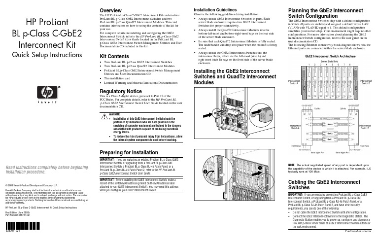
HP ProLiantBL p-Class C-GbE2Interconnect Kit Quick Setup Instructions Read instructions completely before beginninginstallation procedure.© 2003 Hewlett-Packard Development Company, L.P.Hewlett-Packard Company shall not be liable for technical or editorial errors or omissions contained herein. The information in this document is provided “as is” without warranty of any kind and is subject to change without notice. The warranties for HP products are set forth in the express limited warranty statements accompanying such products. Nothing herein should be construed as constituting an additional warranty.HP ProLiant BL p-Class C-GbE2 Interconnect Kit Quick Setup InstructionsFirst Edition (June 2003)Part Number 338797-021338797-021OverviewThe HP ProLiant p-Class C-GbE2 Interconnect Kit contains twoProLiant BL p-Class GbE2 Interconnect Switches and twoProLiant BL p-Class QuadT2 Interconnect Modules. This cardcontains information on how to set up the contents of the kit foryour use.For complete details on installing and configuring the GbE2Interconnect Switch, refer to the HP ProLiant BL p-Class GbE2Interconnect Switch User Guide located on the ProLiant BLp-Class GbE2 Interconnect Switch Management Utilities and UserDocumentation CD included in this kit.Kit Contents• Two ProLiant BL p-Class GbE2 Interconnect Switches• Two ProLiant BL p-Class QuadT2 Interconnect Modules• ProLiant BL p-Class GbE2 Interconnect Switch ManagementUtilities and User Documentation CD• This installation card• Limited Warranty and Material Limitations DocumentationRegulatory NoticeThis is a Class A digital device, pursuant to Part 15 of theFCC Rules. For complete details, refer to the HP ProLiant BLp-Class GbE2 Interconnect Switch User Guide located on the userdocumentation CD.WARNING:• Installation of this GbE2 Interconnect Switch should beperformed by individuals who are both qualified in theservicing of computer equipment and trained in the dangersassociated with products capable of producing hazardousenergy levels.• To reduce the risk of personal injury from hot surfaces, allowthe internal system components to cool before touching.Preparing for InstallationIMPORTANT: If you are replacing an existing ProLiant BL p-Class GbE2Interconnect Switch, or upgrading from a ProLiant BL p-Class GbEInterconnect Switch, a ProLiant BL p-Class RJ-45 Patch Panel, or aProLiant BL p-Class RJ-45 Patch Panel 2, refer to the HP ProLiant BLp-Class GbE2 Interconnect Switch User Guide.IMPORTANT: Before installing the GbE2 Interconnect Switch, make arecord of the switch MAC address (printed on the MAC address labelattached to your GbE2 Interconnect Switch). You may need this addresswhen you configure your GbE2 Interconnect Switch.Installation GuidelinesObserve the following guidelines during installation:• Always install GbE2 Interconnect Switches in pairs. Eachserver blade enclosure requires two GbE2 InterconnectSwitches for proper connectivity.• Always install the QuadT2 Interconnect Modules into thebottom-left-most and bottom-right-most bays on the rear sideof the server blade enclosure.• Be sure that each QuadT2 Interconnect Module is fully seated.The latch/handle will drop into place when the module is firmlyseated.• Always install the GbE2 Interconnect Switches into theinterconnect bays, which are the left-most (side A) andright-most (side B) bays on the front side of the server bladeenclosure.Installing the GbE2 InterconnectSwitches and QuadT2 InterconnectModulesPlanning the GbE2 InterconnectSwitch ConfigurationThe GbE2 Interconnect Switches ship with a default configurationin which all ports are enabled and assigned a default virtual LAN(VLAN) with VLAN ID equal to 1. This default configurationsimplifies your initial setup. Your environment might require otherconfigurations. For more information about planning the GbE2Interconnect Switch configuration, refer to the user guide on theuser documentation CD.The following Ethernet connectivity block diagram shows how theEthernet ports are connected within the server blade enclosure.NOTE: T he actual negotiated speed of any port is dependent uponthe capability of the device to which it is attached. For example, iLOtypically runs at 100 Mb/s.Cabling the GbE2 InterconnectSwitchesIMPORTANT: If you are replacing an existing ProLiant BL p-Class GbE2Interconnect Switch, or upgrading from a ProLiant BL p-Class GbEInterconnect Switch, a ProLiant BL p-Class RJ-45 Patch Panel, or aProLiant BL p-Class RJ-45 Patch Panel 2, and have strict securityrequirements, you can do one of the following:• Do not cable the GbE2 Interconnect Switch until after configuration.• Connect the GbE2 Interconnect Switch to the Diagnostic Station. TheDiagnostic Station enables you to power up, configure, and diagnose aProLiant p-Class server blade or a GbE2 Interconnect Switch outside ofthe rack environment.Continued on reverseConnect the network cables to the QuadT2 InterconnectModules.Item Description 1 Port (22x) RJ-45 connector for 10/100/1000T/TX/T Mb uplink for Switch B2 Port (21x) RJ-45 connector for 10/100/1000T/TX/T Mb uplink for Switch B3 Port (20x) RJ-45 connector for 10/100/1000T/TX/T Mb uplink for Switch B4 Port (19x) RJ-45 connector for 10/100/1000T/TX/T Mb uplink for Switch B5 Port (22x) RJ-45 connector for 10/100/1000T/TX/T Mb uplink for Switch A6 Port (21x) RJ-45 connector for 10/100/1000T/TX/T Mb uplink for Switch A7 Port (20x) RJ-45 connector for 10/100/1000T/TX/T Mb uplink for Switch A8Port (19x) RJ-45 connector for 10/100/1000T/TX/T Mb uplink for Switch APowering Up the GbE2 Interconnect SwitchIf the server blade enclosure has power applied, the GbE2 Interconnect Switch automatically begins to power up when installed. The power status LED on the front of the GbE2 Interconnect Switch will be amber to indicate that power isconnected to the GbE2 Interconnect Switch. After 30 seconds, the power status LED turns to green to indicate that the GbE2 Interconnect Switch is on. After the built-in self-test flashes all LEDs, the active links are illuminated and the power status LED stays green.You can manually force the GbE2 Interconnect Switch to power up by pressing the Pwr/Rst button through the access hole in the front panel of the GbE2 Interconnect Switch, while the power status LED is amber. HP recommends using a small, blunt object for this purpose.CAUTION: Pressing the Pwr/Rst button while the power status LED is green will reset the GbE2 Interconnect Switch.NOTE: If the server blade enclosure does not have power applied, refer to the setup and installation guide for the server blade enclosure .Accessing the GbE2 Interconnect SwitchThe GbE2 Interconnect Switch can be accessed locally using the front panel DB-9 serial management port, or remotely using either the 10/100/1000T/TX/T uplink Ethernet ports in the QuadT2Interconnect Module or the GbE2 Interconnect Switch front panel Ethernet ports.To access the GbE2 Interconnect Switch remotely, you need to assign it an IP address. By default, the GbE2 Interconnect Switch is set up to obtain its IP address from a BOOTP server existing on the attached network.To access the GbE2 Interconnect Switch remotely:1. From the BOOTP server, use the GbE2 Interconnect Switch MAC address to obtain the switch IP address.2. From a computer connected to the same network, use the IP address to access the GbE2 Interconnect Switch using a Web browser or Telnet application. This will allow you to access the GbE2 Interconnect Switch browser-based interface (BBI) or command line interface (CLI). The GbE2 Interconnect Switch logon prompt is displayed.If the GbE2 Interconnect Switch does not obtain the IP address by means of the BOOTP service, you can access the GbE2Interconnect Switch locally and configure the IP address manually. After assigning the IP address to the GbE2 Interconnect Switch, you can then access the switch remotely.To access the GbE2 Interconnect Switch locally:1. Connect the GbE2 Interconnect Switch DB-9 serial connector, using the null-modem serial cable (provided with the following option kits: Scalable Busbar, Mini Busbar, and Power Bus Box), to a local client device (such as a laptop computer) with VT100 terminal emulation software.2. Open a VT100 terminal emulation session with the following settings: 9600 baud rate, eight data bits, no parity, one stop bit, and no flow control.Logging On and Configuring the GbE2 Interconnect SwitchTo log on to the GbE2 Interconnect Switch, use admin for both the default user name and password.NOTE: If you are in the command line interface, you may need to press the ENTER key to display the login prompt.The GbE2 Interconnect Switch comes configured with the factory default configuration. For more information on configuring the GbE2 Interconnect Switch for your network environment, refer to the user guide on the user documentation CD.GbE2 Interconnect Switch Front PanelItem Description Status/Function 1 10G LED Reserved for future use2SAN LEDOff = HP ProLiant BL p-Class GbE2 Storage Connectivity Kit is not installed. On = Refer to the HP ProLiant BL p-Class GbE2 Storage Connectivity Kit Quick Setup Instructions for more information. 3Front panel RJ-45 connector link speed LEDs Amber = 1000 Mb/s Green = 100 Mb/s Off = 10 Mb/s4 Pwr/Rst button Forces the GbE2 Interconnect Switch to power up or reboot5DB-9 connectorUsed to access the local management console6 Front panelRJ-45 connector link activity LEDsGreen = Link and no activityGreen flashing = Link and activity Amber = Port disabled Off = No link7 M anagement status LED Flashing = Management session activeOff = No management session active 8 Power status LED Green = Power on Amber = Stand-by modeOff = Power off 9Link activity and speed LEDsRefer to the following figures and tables for LED assignments and functions.NIC LED FunctionsItem Description Status 1Link speedAmber = 1000 Mb/s Green = 100 Mb/s Off = 10 Mb/s2 Link activityGreen = Link and no activityGreen flashing = Link and activity Amber = Port disabled Off = No linkNIC LED AssignmentsItem Description 1 Server blade slot 1 Ethernet ports 2 Server blade slot 2 Ethernet ports 3 Server blade slot 3 Ethernet ports 4 Server blade slot 4 Ethernet ports 5 Server blade slot 5 Ethernet ports 6 Server blade slot 6 Ethernet ports 7 Server blade slot 7 Ethernet ports 8 Server blade slot 8 Ethernet ports 9 Interswitch cross-connect ports10 Port (19x) RJ-45 connector for rear panel uplink 11 Port (20x) RJ-45 connector for rear panel uplink 12 Port (21x) RJ-45 connector for rear panel uplink 13Port (22x) RJ-45 connector for rear panel uplinkQuadT2 Interconnect Module LEDsItem Description Status1Link activityGreen = Link and no activityGreen flashing = Link and activity Amber = Connector disabled Off = No link 2 Link speedAmber = 1000 Mb/s Green = 100 Mb/s Off = 10 Mb/s。
HP交换机简明使用手册

HP交换机简明使用手册HP5400/5300及HP26002006/10目录HP交换机简明使用手册 (1)第一章交换机的初始配置 (4)1.1使用CONSOLE口进行交换机的配置 (4)1.2使用TELNET或者WEB方式对交换机进行配置 (6)1.2.1使用TELNET方式对交换机进行配置 (6)1.2.2通过WEB方式对交换机进行配置 (6)1.3 设置用户名及密码 (7)1.4 配置SNMP相关信息 (8)1.5 LLDP配置 (9)1.6密码恢复方法 (11)1.7 交换机映像更新及配置文件备份与恢复 (11)1.将配置文件备份到TFTP服务器上 (11)2.将从TFTP服务器上的配置文件恢复到交换机 (12)3.升级交换机的映象文件 (12)第二章二层相关协议设置 (13)2.1端口的命名方式 (13)2.2端口物理参数配置 (13)1.设置端口的工作模式 (14)2.对端口的流量进行限制 (14)2.3 802.1qVLAN的基本概念 (15)2.4基于端口的VLAN划分方法 (15)2.5 GVRP的配置 (16)2.6 TRUNKING(LAG)的配置 (17)2.7 生成树的基本概念(STP/RSTP)及配置方法 (17)2.7.1.生成树的基本概念 (17)2.7.2.生成树的配置方法 (19)2.8 实验 (20)一、演示设备架构 (20)二、基本操作命令 (21)三、演示配置 (22)1、5304xl (22)2、2626_1 (23)3、2626_2 (24)4、测试结果 (24)第三章第三层相关设置 (25)3.1 VLAN间路由的配置 (25)3.2 静态路由的配置 (25)3.3 RIP路由协议基本概念 (26)3.4 RIP的配置 (26)3.5 OSPF路由协议的基本概念 (29)3.6 OSPF的配置 (30)3.7路由重分发 (31)3.8 VRRP/XRRP配置 (32)3.9 DHCP Relay 的配置 (34)第四章安全与认证 (36)4.1端口安全性(MAC绑定) (36)4.2访问控制表 (37)4.2.1标准访问控制列表 (37)4.2.2扩展访问控制表 (37)4.4 802.1X认证(OPEN VLAN) (37)4.5 WEB认证 (39)4.6 MAC认证 (40)4.7病毒抑制的原理与配置 (40)第五章组播协议 (42)5.1组播基本概念 (42)5.2 IGMP的配置 (42)5.3 PIM的配置 (42)附件A:5400交换机的许可证安装与删除 (44)第一章 交换机的初始配置1.1使用CONSOLE口进行交换机的配置1.超级终端配置如下:开始-附件-通讯-超级终端,在COM口属性的窗口中选择还原默认值。
HPDC交换机交维手册

HPDC交换机交维手册HP DC SAN Backbone 交换机日常维护指导手册目录1、目的 (3)2、适用范围 (3)3、硬件设备信息概述 (3)4、登录及配置 (3)4.1 建立一个串行链接,登录到DC SAN Director (3)4.2 配置IP地址 (4)4.3 建立以太网连接 (5)4.4 定制一个交换机的名字 (5)4.5 定制一个机箱的名字 (6)4.6 设置domain ID (6)4.7 验证端口识别模式并连接 (6)4.8 使用软件许可证 (6)4.9 备份配置 (6)5、zone配置方法 (6)5.1 查看 zone 配置 (7)5.2 创建别名 (8)5.3 创建 zone(把别名或端口分配到 zone 中) (8)5.4 创建 zone 配置文件(把 zone 加入到配置文件中) (8)5.5 使 zone 配置生效 (8)5.6 保存配置 (9)6、常用命令及解释 (10)1、目的为保障*****中心HP DC SAN Backbone交换机设备的高效、稳定运行,制订本指导手册。
本手册详细描述了日常检查的主要步骤,从而指导现场工程师对其进行监控和维护。
2、适用范围使用者为****有限公司心工程师。
3、硬件设备信息概述服务器数量:2台,基本信息如下:4、登录及配置4.1 建立一个串行链接,登录到DC SAN Director1. 通过确认LED指示灯均为稳定的绿灯来确认DC SAN Director 已启动,POST已完成。
2.从活跃CP的服务端口移除shipping cap,用DC SAN Director 的串行电缆把服务端口和电脑的工作区域相连接。
3.通过终端应用程序(如Windows环境下的HyperTerminal或者Unix环境下的TERM)来访问DC SAN Director。
4.关闭运行在工作区域的任何串行通信程序(如同步程序)。
5.打开终端模拟应用程序并按如下方式配置:a.对于Microsoft W indows系统:Bits per second—9600 Databits—8 Parity—NoneStop bits—1Flow control—Noneb.对于UNIX 系统:tip /dev/ttyb -9600当终端模拟应用程序不再更新信息,按Enter键接下来登录会出现:CP0 Console Login:6.以admin登录DC SAN Director,默认密码是password7.修改密码密码可以8 - 40个字符长4.2 配置IP地址DC SAN Director默认的IP地址和主机名为:10.77.77.75 / CP0 (配置时,CP 刀片在槽6)10.77.77.74 / CP1 (配置时,CP 刀片在槽7)为CP刀片配置IP地址:1.以admin登录active CP2.通过ipaddrset -sw 0指令配置IP地址:swDir:admin> ipAddrSet -sw 03.通过ipaddrset -cp 0 指令:swDir:admin> ipAddrSet -cp 0建立CP0 IP地址4. Set up the CP1 IP address 通过ipaddrset -cp 1 指令配置CP1 IP地址: swDir:admin> ipAddrSet -cp 1配置IP地址如下例:swDir:admin> ipaddrset -sw 0Ethernet IP Address [0.0.0.0]: 123.123.123.120Ethernet Subnetmask [0.0.0.0]:123.123.123.123 Fibre ChannelIP Address [0.0.0.0]:Fibre ChannelSubnetmask[0.0.0.0]:IssuinggratuitousARP...Done.Committing configuration...Done.swDir:admin> ipaddrset -cp 0Host Name [cp0]:Ethernet IP Address [10.77.77.75]: 123.123.123.121Ethernet Subnetmask [0.0.0.0]: 123.123.123.123Gateway IP Address [0.0.0.0]: 123.123.123.124IP address isbeingchanged...Done.Committingconfiguration...Done.swDir:admin> ipaddrset -cp 1Host Name [cp1]:Ethernet IP Address [10.77.77.74]: 123.123.123.122 Ethernet Subnetmask [0.0.0.0]: 123.123.123.123 Gateway IP Address [0.0.0.0]: 123.123.123.124IP address of remote CP is being changed...Done. Committing configuration...Done.5.执行reboot命令,重启DC SAN Director。
Hp交换机操作手册中文版

第一章交换机的初始配置1.1 使用 CONSOLE 口进行交换机的配置 1.超级终端配置如下:开始-附件-数据位: 2.配置好超级终端后,回车登陆。
H P 系列产品默认需要认证,才能进行管理配置,默认的用户名为空,口令为空。
图:此时将进入登陆模式,登陆模式的符号是一个大于号“>”,在此模式下可以实现基本的状 态查看功能,通过问号“?”可以查看此状态下所有可操作的命令.HP 系列产品所有模式下(登陆模式,管理模式和配置模式)均有这种帮助功能,同时 在输入命令时,可以通过<tab>键进行命令补足.登陆模式:以“>”开头,仅仅能够进行一些基本状态查看管理模式:以“#”开头,能够进行所有状态信息的查看,同一时刻允许有多个管 理员处在此模式下。
从登陆模式进入管理模式的命令:en able (可简写为 e n ),通过 enab le 口令 认证后,即可进入管理模式。
配置模式:以“(con fig)”开头,能够对设备进行配置和管理,同一时刻仅仅允许一个管理人员处在配置模式下。
此模式下可以同时具有管理模式和登陆模式的功能。
从管理模式进入配置模式的命令为:conf igur e,即可进入配置模式。
从高级模式退出到低级模式的命令为exi t或disa b le。
3.基本命令1、查看操作系统版本及硬件信息⓿系统当前版本:⓿系统C P U类型:⓿系统内存容量:⓿系统启动时间:⓿系统当前时间:⓿系统端口类型:⓿系统序列号:⓿系统当前能实现的功能:2.配置主机名:实例:例如需要配置设备的名称为B lue,则命令如下。
ip de fault-gate way<ip-a ddress>B lue(c onfi g)#ip def ault-gat eway192.168.0.1H P系列产品提供了P ing和tra cero ute来检查网路的联通状况p ing命令示例:Blue(config)#pi ng192.168.0.1T racer out e命令示例:Blue(config)#tr aceroute192.168.10.11.2使用TELNET或者WEB方式对交换机进行配置1.2.1使用TELNET方式对交换机进行配置1.配置CLI接口访问语法:show conso le下面图例显示交换机缺省的控制台,串口的配置信息:接口访问允许/禁列出事件值和类型控制台控制选项语法:[no]tel net-server语法:Procurv e(config)#no telnet-s erver语法:Procurv e(config)#t elnet-serv er语法:Procurv e(config)#t elnet192.168.2.351.2.2通过WEB方式对交换机进行配置语法:[no]web-management语法:Procurv e(config)#no web-mana gement语法:Procurv e(config)#w eb-managem ent可以后如下图所示:1.3设置用户名及密码1.通过CLI方式配置用户名和密码对于一个企业的安全来说保密是非常重要的。
HPE FlexFabric 12910 交换机模块说明书

Manual version: 6P103-20160715 BOM: 3123A0Q0 Part number: 5998-4319R LSX1FAB10B1 Switching Fabric Module(JG623A/JH115A)1 Card identifierThe mark LSX1FAB10B1 is printed at the upper left corner of the front panel, and is used to identifythe card.2 SpecificationsTable 1 LSX1FAB10B1 specificationsItem SpecificationProcessor MIPS64 (Dual Core), 1GHz.SDRAM 2GB DDR3 SDRAM.Power consumption 135 W to 170 W.Compatible device models HPE FlexFabric 12910 Switch.NOTE:•To verify compatibility of the card with the software release you are using, see the release notes.•Before you install the card to the switch, remove the protective box for the card.When you install a switching fabric module, hold the ejector levers of the module with both hands,press the buttons on the ejector levers, and pull the ejector levers outward, and then press theejector levers inward after the module is fully seated into the slot.When you remove a switching fabric module, press the buttons on the ejector levers and pull theejector levers outward, and then pull out the switching fabric module.3 Obtaining documentationFor card installation, see the HPE FlexFabric 12900 Switch Series Installation Guide.For software upgrade, see the HPE FlexFabric 12900 Switch Series Software Upgrade Guide.To access documentation and support services, go to the Hewlett Packard Enterprise SupportCenter website:/support/hpesc5998-4319RThe information in this document is subject to change without notice.© Copyright 2016 Hewlett Packard Enterprise Development LP1。
HP A5810-48G 交换机数据手册说明书

HP A5810-48G Switch Data sheetProduct overviewThe HP A5810-48G Switch delivers unparalleled QoS across 48 10/100/1000Base-T Ethernet ports, two multiplex Gigabit Ethernet (GbE) combination SFP ports, and two 10-GbE SFP+ ports for the most demanding enterprise network environments.Key featuresHigh performance for core and distribution "Flex chassis": modular/stackable in onePowerful IPv4/IPv6 ACL/QoS/VoQPowerful buffer capability—24M bufferingRedundant, hot-swappable power supplies, fansFeatures and benefitsManagement•Remote configuration and management: is available through a secure Web browser or a command-line interface (CLI)•IEEE 802.1ab LLDP discovery: advertises and receives management information from adjacent devices on a network•USB support:–File copy: allows users to copy switch files toand from a USB flash drive•DHCP options: client allows automatic setting of IP address•sFlow: provides scalable, ASIC-based, network monitoring and accounting; this allows network operators to gather a variety of sophisticated network statistics and information for capacity planning and real-time network monitoring purposes •SNMPv1, v2c, and v3: facilitate centralized discovery, monitoring, and secure management of networking devicesConnectivity•Auto-MDIX: automatically adjusts forstraight-through or crossover cables on all 10/100 and 10/100/1000 ports•Jumbo frames: on Gigabit and 10-Gigabit ports, allow high-performance remote backup and disaster-recovery services•High-density port connectivity: provides10/100/1000 port configurations up to 80 ports, and an Intelligent Resilient Framework (IRF) stack of up to 576 10/100/1000 portsPerformance•Hardware-based wire-speed access control lists (ACLs): feature-rich ACL implementation (TCAM based) helps ensure high levels of security and ease of administration without impacting network performanceManageability•RMON (remote monitoring): provides advanced monitoring and reporting capabilities for statistics, history, alarms, and events•Web interface: allows configuration of the switch from any Web browser on the network•Multiple configuration files: allow multiple configuration files to be stored to flash image •Troubleshooting: ingress and egress port monitoring enable network problem solvingLayer 2 switching•16K MAC address table: provides access to many Layer 2 devices•4094 port-based VLANs: provide security between workgroups•Gigabit Ethernet port aggregation: allows grouping of ports to increase overall data throughput to a remote device•10 GbE port aggregation: allows grouping of ports to increase overall data throughput to a remote device•Spanning Tree/MSTP, RSTP, and STP Root Guard: prevent network loopsLayer 3 services•Address Resolution Protocol (ARP): determines the MAC address of another IP host in the same subnet; supports static ARPs; gratuitous ARP allows detection of duplicate IP addresses; proxy ARP allows normal ARP operation between subnets or when subnets are separated by a Layer 2 networkLayer 3 routing•Layer 3 IP routing:–Static IP routing: provides basic routing(supporting up to 1K static routes); allows manual configuration of routingSecurity•Port security: allows access only to specified MAC addresses, which can be learned or specified by the administrator•Advanced processor queuing mechanism: helps prevent denial-of-service (DoS) attacks, while DHCP snooping helps ensure that devices can only receive an IP address from a legitimate DHCP server on the network•IEEE 802.1X-based dynamic delivery of QoS, ACLs, and VLANs: allows complete control over user network access•MAC-based authentication: allows or denies access to the switch based on client MAC address•IP source guard: helps prevent IP spoofing attacks•HTTPS management: provides secure Web management•RADIUS/HWTACACS: eases switch managementsecurity administration by using a passwordauthentication server•Secure Shell (SSHv2): encrypts all transmitteddata for secure, remote command-line interface (CLI)access over IP networksConvergence•LLDP-MED: is a standard extension thatautomatically configures network devices, includingLLDP-capable IP phonesMonitor and diagnostics•Port mirroring: enables traffic on a port to besimultaneously sent to a network analyzer formonitoringAdditional information•Green IT and power: use the latest advances insilicon development, shut off unused ports, and usevariable-speed fans to improve power efficiencyWarranty and support•Lifetime warranty: for as long as you own theproduct with advance replacement andnext-business-day delivery (available in mostcountries)*•Electronic and telephone support: limitedelectronic and telephone support is available fromHP; refer to /networking/warranty fordetails on the support provided and the periodduring which support is available•Software releases: refer to/networking/warranty for details onthe software releases provided and the periodduring which software releases are available foryour product(s)*Hardware warranty replacement for as long as you own the product, with next business day advance replacement (available in most countries) with a five-year hardware warranty replacement for the disk drive included with HP AllianceONE Services zl Module, HP Threat Management Services zl Module, HP PCM+ Agent with AllianceONE Services zlSpecificationsHP A5810-48G Switch (JF242A)Ports48 RJ-45 auto-negotiating 10/100/1000 ports (IEEE 802.3 Type 10Base-T, IEEE 802.3u Type 100Base-TX, IEEE 802.3ab Type 1000Base-T)2 SFP 100/1000 Mbps ports2 SFP+ fixed 1000/10000 SFP+ ports; Duplex: full only1 RJ-45 serial console portPower supplies 2 power-supply slots1 minimum power-supplies required (ordered separately)Physical characteristicsDimensions16.54(d) x 17.32(w) x 1.72(h) in. (42 x 44 x 4.36 cm) (1U height)Weight17.64 lb. (8 kg)Memory and processor512 MB SDRAM, 512 MB flash; packet buffer size: 24 MBMounting Mounts in EIA-standard 19 in. telco rack or equipment cabinet (hardware included)PerformanceThroughput up to 101 million ppsRouting/Switching capacity136 GbpsMAC address table size16,000 entriesEnvironmentOperating temperature32°F to 113°F (0°C to 45°C)Operating relative humidity10% to 90%, non-condensingElectrical characteristicsMaximum heat dissipation614 BTU/hr (647.77 kJ/hr)Voltage100-120 / 200-240 VACFrequency50 / 60 HzSafety UL 60950-1; EN 60825-1 Safety of Laser Products-Part 1; EN 60825-2 Safety of Laser Products-Part 2; IEC 60950-1; CAN/CSA-C22.2 No. 60950-1; Anatel;ULAR; GOST; EN 60950-1/A11; FDA 21 CFR Subchapter J; NOM; ROHS ComplianceEmissions VCCI Class A; EN 55022 Class A; ICES-003 Class A; ANSI C63.4 2003; AS/NZS CISPR22 Class A; EN 61000-3-2:2006; EN 61000-3-3:1995+A1:2001+A2:2005; EMC Directive 2004/108/EC; FCC (CFR 47, Part 15) Class AImmunityGeneric ETSI EN 300 386 V1.3.3EN EN 55024:1998+ A1:2001 + A2:2003ESD EN 61000-4-2; IEC 61000-4-2Radiated EN 61000-4-3; IEC 61000-4-3EFT/Burst EN 61000-4-4; IEC 61000-4-4Surge EN 61000-4-5; IEC 61000-4-5Conducted EN 61000-4-6; IEC 61000-4-6Power frequency magnetic field IEC 61000-4-8; EN 61000-4-8Voltage dips and interruptions EN 61000-4-11; IEC 61000-4-11Harmonics EN 61000-3-2, IEC 61000-3-2Flicker EN 61000-3-3, IEC 61000-3-3Management IMC - Intelligent Management Center; command-line interface; Web browser; out-of-band management; SNMP Manager; Telnet; HTTPS; RMON1; FTPNotes A5810 switch provides a power module when shipped. Customer can select two power modules to implement 1+1 power supply redundancy.Services3-year, 4-hour onsite, 13x5 coverage for hardware (UV882E)3-year, 4-hour onsite, 24x7 coverage for hardware (UV885E)3-year, 4-hour onsite, 24x7 coverage for hardware, 24x7 software phone support (UV888E)3-year, 24x7 SW phone support, software updates (UV891E)4-year, 4-hour onsite, 13x5 coverage for hardware (UV883E)4-year, 4-hour onsite, 24x7 coverage for hardware (UV886E)4-year, 4-hour onsite, 24x7 coverage for hardware, 24x7 software phone (UV889E)4-year, 24x7 SW phone support, software updates (UV892E)5-year, 4-hour onsite, 13x5 coverage for hardware (UV884E)5-year, 4-hour onsite, 24x7 coverage for hardware (UV887E)5-year, 4-hour onsite, 24x7 coverage for hardware, 24x7 software phone (UV890E)5-year, 24x7 SW phone support, software updates (UV893E)3 Yr 6 hr Call-to-Repair Onsite (UW969E)4 Yr 6 hr Call-to-Repair Onsite (UW970E)5 Yr6 hr Call-to-Repair Onsite (UW971E)Specifications (continued)HP A5810-48G Switch (JF242A)Refer to the HP website at /networking/services for details on the service-level descriptions and product numbers. For details about services andresponse times in your area, please contact your local HP sales office.Standards and protocols General protocolsIEEE 802.1ag Service Layer OAMIEEE 802.1D MAC BridgesIEEE 802.1p PriorityIEEE 802.1Q VLANsIEEE 802.1s (MSTP)IEEE 802.1v VLAN classification by Protocol andPortIEEE 802.1w Rapid Reconfiguration of SpanningTreeIEEE 802.1X PAEIEEE 802.3ad Link Aggregation Control Protocol(LACP)IEEE 802.3ae 10-Gigabit EthernetIEEE 802.3x Flow ControlRFC 768 UDPRFC 792 ICMPRFC 793 TCPRFC 826 ARPRFC 854 TELNETRFC 925 Multi-LAN Address ResolutionRFC 951 BOOTPRFC 1519 CIDRRFC 1542 BOOTP ExtensionsRFC 2131 DHCPRFC 3576 Ext to RADIUS (CoA only)RFC 4675 RADIUS VLAN & Priority MIBsIEEE8021-PAE-MIBIEEE8023-LAG-MIBRFC 1213 MIB IIRFC 1493 Bridge MIBRFC 2011 SNMPv2 MIB for IPRFC 2013 SNMPv2 MIB for UDPRFC 2233 Interface MIBRFC 2273 SNMP-NOTIFICATION-MIBRFC 2571 SNMP Framework MIBRFC 2572 SNMP-MPD MIBRFC 2573 SNMP-Notification MIBRFC 2618 RADIUS Client MIBRFC 2620 RADIUS Accounting MIBRFC 2665 Ethernet-Like-MIBRFC 2674 802.1p and IEEE 802.1Q Bridge MIBRFC 2688 MAU-MIBRFC 2819 RMON MIBRFC 2925 Ping MIBRFC 3414 SNMP-User based-SM MIBRFC 3415 SNMP-View based-ACM MIBRFC 3418 MIB for SNMPv3RFC 3826 AES for SNMP's USM MIBRFC 4133 Entity MIB (Version 3)LLDP-EXT-DOT1-MIBLLDP-EXT-DOT3-MIBLLDP-MIBNetwork managementIEEE 802.1AB Link Layer Discovery Protocol (LLDP)RFC 2819 Four groups of RMON: 1 (statistics), 2(history), 3 (alarm) and 9 (events)RFC 3176 sFlowANSI/TIA-1057 LLDP Media Endpoint Discovery(LLDP-MED)SNMPv1/v2c/v3SecurityIEEE 802.1X Port Based Network Access ControlRFC 1492 TACACS+RFC 2865 RADIUS (client only)RFC 2866 RADIUS AccountingSecure Sockets Layer (SSL)SSHv2 Secure ShellHP A5810-48G Switch accessories© Copyright 2010 Hewlett-Packard Development Company, L.P. The information contained herein is subject to change without notice. The only warranties for HP products and services are set forth in the express warranty statements accompanying such products and services. Nothing herein should be construed as constituting an To learn more, visit /networkingTransceiversHP X124 1G SFP LC LH40 1310nm Transceiver (JD061A)HP X120 1G SFP LC LH40 1550nm Transceiver (JD062A)HP X125 1G SFP LC LH70 Transceiver (JD063B)HP X110 100M SFP LC LH40 Transceiver (JD090A)HP X110 100M SFP LC LH80 Transceiver (JD091A)HP X130 SFP+ LC SR Transceiver (JD092B)HP X130 SFP+ LC LRM Transceiver (JD093B)HP X130 SFP+ LC LR Transceiver (JD094B)HP X110 100M SFP LC FX Transceiver (JD102B)HP X125 1G SFP LC SX Transceiver (JD118B)HP X120 1G SFP LC LX Transceiver (JD119B)HP X110 100M SFP LC LX Transceiver (JD120B)HP X240 SFP+ SFP+ 0.65 m Direct Attach Cable (JD095B)HP X240 SFP+ SFP+ 1.2 m Direct Attach Cable (JD096B)HP X240 SFP+ SFP+ 3 m Direct Attach Cable (JD097B)CablesNEW HP 0.5 m PremierFlex OM3+ LC/LC Optical Cable(BK837A)Power SupplyHP A5800 300W AC Power Supply (JC087A)Fan TrayHP A5800 1RU Spare Fan Assembly (JC098A)。
HP P2000G3存储官方配置文档(中文)
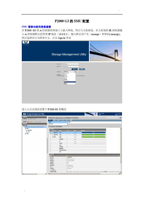
P2000 G3的SMU配置SMU登录与相关信息查看在P2000 G3的A控制器管理端口上插入网线,然后与主机相连,在主机端的IE浏览器输入A控制器默认的管理IP地址(10.0.0.2),输入默认用户名(manage)和密码(!manage),然后选择语言为简体中文,点击Sign In登录进入之后出现的是整个P2000 G3的概况可以点击系统事件中的各种事件符号查看事件,也可直接点击视图中的事件日志进行查看点击系统概况中磁盘的状态,可以看到当前状态为A V AIL,即还没有做阵列点击左侧配置视图中的物理---机箱,然后右侧会出现机箱概况,通过正面图形,可以看到P2000 G3当前硬盘状态和机箱状态。
其中机箱属性中:中板序列号即为本台存储的S/N号。
点击背面图形,可以查看当前存储的硬件故障信息,因为B控制器的管理接口没接网线,另外一个电源没有接线,所以会有报错。
配置向导第一次进入SMU,可以通过配置向导来更改系统的基本配置。
选中左侧配置视图中的P2000 G3,然后点击菜单栏:配置---配置向导密码设置(可以更改manage和monitor用户的密码)网络配置(可以更改两个控制器的管理IP地址)启用或者禁用系统管理服务系统信息事件通知配置控制器接口(FC和iSCSI)配置配置完成设置向导第一次进入SMU,可以使用设置向导来配置虚拟磁盘和卷以及映射。
在配置视图中点击P2000 G3,然后点击菜单栏---向导---设置向导(或设置中的设置向导)虚拟磁盘设置:给虚拟磁盘命名,选择RAID级别,选择要指定的控制器,然后点击下一步选择磁盘:勾选要加入此虚拟磁盘的物理硬盘后点击下一步创建卷:输入要创建的卷数目,卷大小和基本名称,然后点击下一步映射卷:勾选映射,勾选要映射的控制器的接口,输入LUN号(注意LUN不要为0),选择控制器对此卷的访问权限确认信息后完成向导设置完成后,可以点击P2000 G3,查看当前磁盘状态为VDISKINIT状态,而非做阵列前得A V AI状态点击卷,然后点击映射,确认当前卷已经映射成功主机端的操作在主机端的磁盘管理中点击重新扫描磁盘后,会发现逻辑磁盘(注意,如果主机和存储的链接为双链路,则会把每个光纤通道的映射都识别为一个逻辑磁盘,需要下载MPIO软件)常用的驱动软件为SES Driver(磁盘阵列驱动)和MPIO DSM(多路径软件)以2003为例/bizsupport/TechSupport/SoftwareIndex.jsp?lang=en&cc=us&prodNameId=4118572&prodTypeId=12169&prodSeriesId=4118559&swLang=8&taskId=135&swEnvOI D=1005#113214安装好MPIO软件后,在设备管理器---SCSI和RAID控制器中会多出Multi-Path Support设备点击磁盘管理,这次映射的卷在主机的磁盘管理中可以正确的显示为一个逻辑磁盘。
HP DC 交换机交维手册

HP DC SAN Backbone 交换机日常维护指导手册目录1、目的 (3)2、适用范围 (3)3、硬件设备信息概述 (3)4、登录及配置 (3)4.1 建立一个串行链接,登录到DC SAN Director (3)4.2 配置IP地址 (4)4.3 建立以太网连接 (5)4.4 定制一个交换机的名字 (5)4.5 定制一个机箱的名字 (6)4.6 设置domain ID (6)4.7 验证端口识别模式并连接 (6)4.8 使用软件许可证 (6)4.9 备份配置 (6)5、zone配置方法 (6)5.1 查看 zone 配置 (7)5.2 创建别名 (8)5.3 创建 zone(把别名或端口分配到 zone 中) (8)5.4 创建 zone 配置文件(把 zone 加入到配置文件中) (8)5.5 使 zone 配置生效 (8)5.6 保存配置 (9)6、常用命令及解释 (10)1、目的为保障*****中心HP DC SAN Backbone交换机设备的高效、稳定运行,制订本指导手册。
本手册详细描述了日常检查的主要步骤,从而指导现场工程师对其进行监控和维护。
2、适用范围使用者为****有限公司心工程师。
3、硬件设备信息概述服务器数量:2台,基本信息如下:4、登录及配置4.1 建立一个串行链接,登录到DC SAN Director1. 通过确认LED指示灯均为稳定的绿灯来确认DC SAN Director已启动,POST已完成。
2.从活跃CP的服务端口移除shipping cap,用DC SAN Director的串行电缆把服务端口和电脑的工作区域相连接。
3.通过终端应用程序(如Windows环境下的HyperTerminal或者Unix环境下的TERM)来访问DC SAN Director。
4.关闭运行在工作区域的任何串行通信程序(如同步程序)。
5.打开终端模拟应用程序并按如下方式配置:a.对于Microsoft W indows系统:Bits per second—9600 Databits—8 Parity—NoneStop bits—1Flow control—Noneb.对于UNIX 系统:tip /dev/ttyb -9600当终端模拟应用程序不再更新信息,按Enter键接下来登录会出现:CP0 Console Login:6.以admin登录DC SAN Director,默认密码是password7.修改密码密码可以8 - 40个字符长4.2 配置IP地址DC SAN Director默认的IP地址和主机名为:10.77.77.75 / CP0 (配置时,CP 刀片在槽6)10.77.77.74 / CP1 (配置时,CP 刀片在槽7)为CP刀片配置IP地址:1.以admin登录active CP2.通过ipaddrset -sw 0指令配置IP地址:swDir:admin> ipAddrSet -sw 03.通过ipaddrset -cp 0 指令:swDir:admin> ipAddrSet -cp 0建立CP0 IP地址4. Set up the CP1 IP address 通过ipaddrset -cp 1 指令配置CP1 IP地址: swDir:admin> ipAddrSet -cp 1配置IP地址如下例:swDir:admin> ipaddrset -sw 0Ethernet IP Address [0.0.0.0]: 123.123.123.120Ethernet Subnetmask [0.0.0.0]:123.123.123.123 Fibre ChannelIP Address [0.0.0.0]:Fibre ChannelSubnetmask[0.0.0.0]:IssuinggratuitousARP...Done.Committing configuration...Done.swDir:admin> ipaddrset -cp 0Host Name [cp0]:Ethernet IP Address [10.77.77.75]: 123.123.123.121Ethernet Subnetmask [0.0.0.0]: 123.123.123.123Gateway IP Address [0.0.0.0]: 123.123.123.124IP address isbeingchanged...Done.Committingconfiguration...Done.swDir:admin> ipaddrset -cp 1Host Name [cp1]:Ethernet IP Address [10.77.77.74]: 123.123.123.122Ethernet Subnetmask [0.0.0.0]: 123.123.123.123Gateway IP Address [0.0.0.0]: 123.123.123.124IP address of remote CP is beingchanged...Done. Committingconfiguration...Done.5.执行reboot命令,重启DC SAN Director。
HP ProCurve 2910al交换机系列 说明书

• 查找-解决-通知:自动查找并解决常见的网络问题,然后通知管 理员。
全新 HP ProCurve 10-GbE SFP+ 1米直连电缆(J9281A) 全新 HP ProCurve 10-GbE SFP+ 3米直连电缆(J9283A)
• 双闪存映像:可提供独立的主、辅操作系统文件,以便在升级过 程中进行备份
• 多配置文件:允许多个配置文件存储到闪存映像中。 • 易用的端口名称:允许为端口指定描述性名称
HP ProCurve 620冗余/外置电源(J8696A) HP ProCurve 100-FX SFP-LC收发器(J9054B) 全新 HP ProCurve 100-BX-D SFP-LC收发器(J9099B) 全新 HP ProCurve 100-BX-U SFP-LC收发器(J9100B) HP ProCurve Gigabit-SX-LC Mini-GBIC (J4858C) HP ProCurve Gigabit-LX-LC Mini-GBIC (J4859C) HP ProCurve Gigabit-LH-LC Mini-GBIC (J4860C) 全新 HP ProCurve 1000-BX-D SFP-LC Mini-GBIC (J9142B) 全新 HP ProCurve 1000-BX-U SFP-LC Mini-GBIC (J9143B) 全新 HP ProCurve 10-GbE SFP+ SR收发器(J9150A) 全新 HP ProCurve 10-GbE SFP+ LR收发器(J9151A) 全新 HP ProCurve 10-GbE SFP+ LRM收发器(J9152A)
电缆
安全性
• 多种用户身份验证方法:
Hp交换机操作手册中文版

Hp交换机操作⼿册中⽂版第⼀章交换机的初始配置1.1使⽤CONSOLE⼝进⾏交换机的配置1〃超级终端配置如下:开始-附件-通讯-超级终端,在COM⼝属性的窗⼝中选择还原默认值。
每秒位数(B):9600数据位(D):8奇偶校验(P):⽆停⽌位(S):1数据流控制(F):⽆2〃配置好超级终端后,回车登陆。
H P系列产品默认需要认证,才能进⾏管理配置,默认的⽤户名为空,⼝令为空。
图:此时将进⼊登陆模式,登陆模式的符号是⼀个⼤于号“>”,在此模式下可以实现基本的状态查看功能,通过问号“?”可以查看此状态下所有可操作的命令.HP系列产品所有模式下(登陆模式,管理模式和配置模式)均有这种帮助功能,同时在输⼊命令时,可以通过键进⾏命令补⾜.登陆模式:以“>”开头,仅仅能够进⾏⼀些基本状态查看管理模式:以“#”开头,能够进⾏所有状态信息的查看,同⼀时刻允许有多个管理员处在此模式下。
从登陆模式进⼊管理模式的命令:en able(可简写为e n),通过enab le⼝令认证后,即可进⼊管理模式。
配置模式:以“(con fig)”开头,能够对设备进⾏配置和管理,同⼀时刻仅仅允许⼀个管理⼈员处在配置模式下。
此模式下可以同时具有管理模式和登陆模式的功能。
从管理模式进⼊配置模式的命令为:conf igur e,即可进⼊配置模式。
从⾼级模式退出到低级模式的命令为exi t或disa b le。
3〃基本命令1、查看操作系统版本及硬件信息命令:s h o w v er sion作⽤:查看当前系统版本和状态信息系统当前版本:test_5304x l#s h o w v ers i onIm age sta mp:/s w/c ode/buil d/al pm o(m35)A ug2200511:27:11E.10.044015B oot Im age:Pr i m ar y系统主机名:系统C P U类型:系统内存容量:系统启动时间:系统当前时间:系统端⼝类型:系统序列号:系统当前能实现的功能:2.配置主机名:命令:hostname:其中主机名长度最长为64字节实例:例如需要配置设备的名称为B lue,则命令如下。
HP-iLO2-iLO3管理口配置及使用手册
HP integrated Light-Out 2 远程管理卡(iLO2)操作指南QQ1656749CONTENTSCONTENTS (2)1.ILO2远程管理卡简介 (3)1.1.I LO2是什么 (3)1.2.I LO2的使用模式 (3)2.ILO2的基本设置 (4)2.1.I LO2的网络连接方式 (4)2.2.I LO2的网络及用户设置 (4)3.使用ILO2管理远程服务器 (9)3.1.I LO2所需的浏览器设置 (9)3.1.1.浏览器版本 (9)3.1.2.浏览器的ActiveX设置 (9)3.2.使用浏览器访问I LO2 (11)3.3.使用浏览器管理I LO2 (12)3.3.1.升级iLO2的Firmware (12)3.3.2.升级iLO2的License (13)3.3.3.用户管理 (13)3.3.4.网络及其他设置 (14)3.4.使用I LO2查看系统信息和日志 (16)3.5.使用I LO2的远程控制台功能 (18)3.6.使用I LO2的虚拟介质功能 (20)3.6.1.虚拟电源 (20)3.6.2.功率调节器 (21)3.6.3.虚拟介质 (22)4.ILO2远程管理卡特性总结 (24)1. iLO2远程管理卡简介1.1.iLO2是什么iLO(Integrated Lights-Out)是HP独有的服务器远程管理技术.如今的商业要求需要服务器能在任何时间和地点都能提供24小时不间断的管理能力. 公司不再需要为雇用的主管提供奢侈的远程场所,或为了远程服务器的维护而花费更多时间。
为了满足这些日益增长的响应需求,需要服务器具有易用的远程管理功能.为此, HP发展了Integrated Lights-Out技术。
Integrated Lights-Out 是一个可通过任何服务器状态来管理主机服务器的自主管理分系统:操作系统加载前的初始开机测试,,即使系统失败它仍具备此功能. 实际上, Integrated Lights-Out 是一个计算机内部的自主计算机系统:高度优化的体系结构,包括特有的使用单独指令集和数据缓存的RISC 处理器,内存子系统和以太网控制器,Integrated Lights-Out 提供一个可以让管理员控制的具有图形方式的远程管理控制平台,实现对服务器在任意时间和在任意操作系统下的图形方式控制。
hp交换机命令大全

第一章交换机的初始配置1.1使用CONSOLE口进行交换机的配置1.超级终端配置如下:开始-附件-通讯-超级终端,在COM口属性的窗口中选择还原默认值。
每秒位数(B):9600数据位(D):8奇偶校验(P):无停止位(S):1数据流控制(F):无2.配置好超级终端后,回车登陆。
H P系列产品默认需要认证,才能进行管理配置,默认的用户名为空,口令为空。
图:此时将进入登陆模式,登陆模式的符号是一个大于号“>”,在此模式下可以实现基本的状态查看功能,通过问号“?”可以查看此状态下所有可操作的命令.HP系列产品所有模式下(登陆模式,管理模式和配置模式)均有这种帮助功能,同时在输入命令时,可以通过<tab>键进行命令补足.z登陆模式:以“>”开头,仅仅能够进行一些基本状态查看z管理模式:以“#”开头,能够进行所有状态信息的查看,同一时刻允许有多个管理员处在此模式下。
从登陆模式进入管理模式的命令:en able(可简写为e n),通过enab le口令认证后,即可进入管理模式。
z配置模式:以“(con fig)”开头,能够对设备进行配置和管理,同一时刻仅仅允许一个管理人员处在配置模式下。
此模式下可以同时具有管理模式和登陆模式的功能。
从管理模式进入配置模式的命令为:conf igur e,即可进入配置模式。
从高级模式退出到低级模式的命令为exi t或disa b le。
3.基本命令1、查看操作系统版本及硬件信息‹系统当前版本:‹系统C P U类型:‹系统内存容量:‹系统启动时间:‹系统当前时间:‹系统端口类型:‹系统序列号:‹系统当前能实现的功能:2.配置主机名:实例:例如需要配置设备的名称为B lue,则命令如下。
4.配置网关:H P 系列产品提供了 P ing 和 tra cero ute 来检查网路的联通状况1.2 使用 TELNET 或者 WEB 方式对交换机进行配置1.2.1 使用 TELNET 方式对交换机进行配置1.配置 CLI 接口访问下面图例显示交换机缺省的控制台,串口的配置信息:1.2.2 通过 WEB 方式对交换机进行配置可以使用Http://192.168.0.3(该地址为虚拟地址,客户可根据具体的设置改动),一切OK 后如下图所示:1.3设置用户名及密码1.通过CLI方式配置用户名和密码对于一个企业的安全来说保密是非常重要的。
DS-3E0106HP 100Mbps 远程PoE交换机用户手册说明书
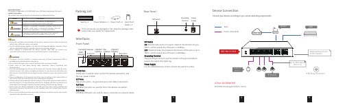
2345Device ConnectionConnect your devices according to your actual networking requirements.InterfacesRear PanelFront PanelPacking List1Switch x 1Quick StartGuide x 1Power Cord x 1Hi-PoE PortHi-PoE port is used for other Hi-PoE PTZ cameras connection, and the max. power is 60 W .1/2 PortsHigh priority ports, can guarantee prior and stable transmission .PoE Ports100 Mbps PoE ports are used for other PoE devices connection .RJ45 Ports100 Mbps RJ45 ports are used for device connection via network cables .LINK/ACT Indicator PoE Indicator PoE-MAX Indicator PWRIndicatorPoE Ports RJ45 PortsGrounding TerminalPower SupplyLINK/ACTIndicator Power Adapter x 1Applicable ModelsThis manual is applicable to DS-3E0106HP series 100 Mbps Long-Range PoE switch.Symbol ConventionsThe symbols that may be found in this document are defined as follows.During the installation and utilization of the device, please strictly conform to electrical safety rules in different nations and regions.Use the attached power adaptor only and not to change the adaptor randomly. Please refer to specification table for specific requirements of power adaptor.Never attempt to disassemble the device yourself. (We shall not assume any responsibility for problems caused by unauthorized repair or maintenance.)The device must be installed in machine room only, and only maintenance staff or qualified person should access to the device.Do not touch the upper cover area of the device that may be overheated.Power must be shut down during cable connection, device installation and dismantlement.You shall acknowledge that the use of the device with Internet access might be under network security risks, please strengthen protection for your personal information and data security. If you find the device might be under network security risks, please contact with us.Proper configuration of all passports and other security settings is the responsibility of the installer, and you shall keep user name and passports properly.Please keep all original packing materials properly. If the product does not work properly, pack the switch in its original packing materials for shipping. We shall not assume any responsibility for damages caused by improper packing materials during shipping.Ensure that your devices powered via the PoE port have their shells protected and fire-proofed, because the switches are not compliant with the Limited Power Source (LPS) standard.This is a class A product and may cause radio interference in which case the user may be required to take adequate measures.Indicates a hazard with a high level of risk, which if not avoided, will result in death or serious injury.SymbolDescriptionProvides additional information to emphasize or supplement important points of the main text.Indicates a potentially hazardous situation, which if not avoided, could result in equipment damage, data loss, performance degradation, or unexpected results.•••••••••••DIP SwitchON : Extend mode, ports 1-4 support network transmission of up to 300 m, and the speed rate of the port is 10 Mbps.OFF : Standard mode, the network transmission of PoE ports is up to 100 m, and the speed rate of the port is 100 Mbps.Grounding TerminalThe grounding terminal is used to connect to the ground cable to protect the switch from lightning.Power SupplyUse the attached power cord to connect the switch to socket.If any accessories are damaged or lost, keep the package intact and contact your dealer for replacement.DIP Switch4-Port 10/100M PoE10/100M Unmanaged PoE Pro-SeriesDS-3E0106HP4-Port 100 Mbps Long-Range PoE SwitchQuick Start GuideUD13637B-A678Power-On CheckingSee the following table and check whether your devices are correctly connected. After proper connection, you can use your switch without doing any settings.The switch supports auto MDI/MDIX of ports, you can usestraight-through cable or crossover cable to connect the switch and opposite Ethernet devices.Regulatory InformationFCC InformationPlease take attention that changes or modification not expressly approved by the party responsible for compliance could void the user’s authority to operate the equipment.FCC compliance: This equipment has been tested and found to comply with the limits for a Class A digital device, pursuant to part 15 of the FCC Rules. These limits are designed to provide reasonable protection against harmful interference when the equipment is operated in a commercial environment. This equipment generates, uses, and can radiate radio frequency energy and, if not installed and used in accordance with the instruction manual, may cause harmful interference to radio communications. Operation of this equipment in a residential area is likely to cause harmful interference in which case the user will be required to correct the interference at his own expense.FCC ConditionsThis device complies with part 15 of the FCC Rules. Operation is subject to the following two conditions:1. This device may not cause harmful interference.2. This device must accept any interference received, including interference that may cause undesired operation.EU Conformity StatementThis product and - if applicable - the supplied accessories too are marked with "CE" and comply therefore with the applicable harmonized European standards listed under the EMC Directive 2014/30/EU, the LVD Directive 2014/35/EU,the RoHS Directive 2011/65/EU.2012/19/EU (WEEE directive): Products marked with this symbol cannot be disposed of as unsorted municipal waste in the European Union. For properrecycling,returnthis product to your local supplier upon the purchase of equivalent new equipment, or dispose of it at designated collection points.For more information see: 2006/66/EC (battery directive): This product contains a battery that cannot be disposed of as unsorted municipal waste in the European Union. See the product documentation for specific battery information. The battery is marked with this symbol, which may include lettering to indicate cadmium (Cd), lead (Pb),or mercury (Hg). For proper recycling, return the battery to your supplier or to a designated collection point. For more information see: Industry Canada ICES-003 ComplianceThis device meets the CAN ICES-3 (A)/NMB-3(A) standards requirements.Quick Start GuideCOPYRIGHT ©2019 Hangzhou Hikvision Digital Technology Co., Ltd. ALL RIGHTS RESERVED.Any and all information, including, among others, wordings, pictures, graphs are the properties of Hangzhou Hikvision Digital Technology Co., Ltd. or its subsidiaries (hereinafter referred to be “Hikvision”). This user manual (hereinafter referred to be “the Manual”) cannot be reproduced, changed, translated, or distributed, partially or wholly, by any means, without the prior written permission of Hikvision. Unless otherwise stipulated, Hikvision does not make any warranties, guarantees or representations, express or implied, regarding to the Manual.About this ManualThe Manual includes instructions for using and managing the product. Pictures, charts, images and all other information hereinafter are for description and explanation only. The information contained in the Manual is subject to change, without notice, due to firmware updates or other reasons. Please find the latest version in the company website (/en/).Please use this user manual under the guidance of professionals.Trademarks Acknowledgementand other Hikvision’s trademarks and logos are the properties of Hikvision in various jurisdictions. Other trademarks and logos mentioned below are the properties of their respective owners.Legal DisclaimerTO THE MAXIMUM EXTENT PERMITTED BY APPLICABLE LAW, THE PRODUCT DESCRIBED, WITH ITS HARDWARE, SOFTWARE AND FIRMWARE, IS PROVIDED “AS IS”, WITH ALL FAULTS AND ERRORS, AND HIKVISION MAKES NO WARRANTIES, EXPRESS OR IMPLIED, INCLUDING WITHOUT LIMITATION, MERCHANTABILITY, SATISFACTORY QUALITY, FITNESS FOR A PARTICULAR PURPOSE, AND NON-INFRINGEMENT OF THIRD PARTY. IN NO EVENT WILL HIKVISION, ITS DIRECTORS, OFFICERS, EMPLOYEES, OR AGENTS BE LIABLE TO YOU FOR ANY SPECIAL, CONSEQUENTIAL, INCIDENTAL, OR INDIRECT DAMAGES, INCLUDING, AMONG OTHERS, DAMAGES FOR LOSS OF BUSINESS PROFITS, BUSINESS INTERRUPTION, OR LOSS OF DATA OR DOCUMENTATION, IN CONNECTION WITH THE USE OF THIS PRODUCT, EVEN IF HIKVISION HAS BEEN ADVISED OF THE POSSIBILITY OF SUCH DAMAGES.REGARDING TO THE PRODUCT WITH INTERNET ACCESS, THE USE OF PRODUCT SHALL BE WHOLLY AT YOUR OWN RISKS. HIKVISION SHALL NOT TAKEANY RESPONSIBILITES FOR ABNORMAL OPERATION, PRIVACY LEAKAGE OR OTHER DAMAGES RESULTING FROM CYBER ATTACK, HACKER ATTACK, VIRUS INSPECTION, OR OTHER INTERNET SECURITY RISKS; HOWEVER, HIKVISION WILL PROVIDE TIMELY TECHNICAL SUPPORT IF REQUIRED.SURVEILLANCE LAWS VARY BY JURISDICTION. PLEASE CHECK ALL RELEVANT LAWS IN YOUR JURISDICTION BEFORE USING THIS PRODUCT IN ORDER TO ENSURE THAT YOUR USE CONFORMS THE APPLICABLE LAW. HIKVISION SHALL NOT BE LIABLE IN THE EVENT THAT THIS PRODUCT IS USED WITH ILLEGITIMATE PURPOSES.IN THE EVENT OF ANY CONFLICTS BETWEEN THIS MANUAL AND THE APPLICABLE LAW, THE LATER PREVAILS.。
HP IP控制台交换机 快速指南

KVM交换机
您是否需要亲自到服务器机房才能对服务器进行操作? 一名用户只可访问一台服务器。 如果能够将不同的任务分配给多人执行,工作效率将会得到显著提升。
IP控制台交换机可帮助您能够通过网络实现对多台服务器的连接和访问!
IP控制台交换机有何用途?
执行远程操作 集成虚拟介质
访问多台服务器 支持多厂商服务器 2
最多可连接4096台服务器。
问3 IP控制台交换机与iLO有何差异? 答3 尽管iLO和IP控制台交换机包含有多种功能相同的组件,但是两者的结合使用有助于简
化服务器管理
IP控制台交换机和iLO之间的差异
iLO • 适用于单台服务器 • 采用虚拟FD时,必须为每台服务器独 立购买许可 (*刀片服务器除外)
扫描模式具备出色的监控功能,可帮助您即时响应发生的问题! 另外,直观的操作界面不仅易于理解,而且方便操作!
6
问5 如何在发生系统故障后,提升恢复操作的效率? 答5 可使用“数字共享”模式。该模式可最多支持12名用户同时访问一台服务器。
“数字共享”模式是IP控制台交换机的一项主要功能。它支持在故障发生后 将恢复操作任务分配给多人执行,以便最大限度地缩短宕机时间!
• 需要管理大量的服务器 • 在多个远程站点安装有服务器 • 并不是每台服务器均配备有CD/DVD光驱 • 希望集中管理不同厂商的服务器 • 希望提升服务器管理的安全性 • 在多个位置集中部署了IT人员和机构 • 需要远程访问能力以及较长的正常运行时间 • 需要对服务器进行BIOS级别的访问
系统组件
IP控制台交换机和KVM交换机之间的主要差别包括:
KVM交换机 仅能够访问本地机架上的服务器。因 此,系统管理员必须要亲自在服务器机 房内执行各种任务。
hp thinpro pc 转换器部署工具管理员指南说明书

HP ThinPro PC Converter 部署工具©Copyright 2019 HP Development Company, L.P.Windows 是 Microsoft Corporation 在美国和/或其他国家/地区的注册商标或商标。
保密的计算机软件。
需要有 HP 颁发的有效许可证才能拥有、使用或复制。
与 FAR 12.211 和 12.212 相一致,依据供应商的标准商业许可将“商业计算机软件、计算机软件文档和用于商业单位的技术数据”许可给美国政府使用。
本文档中包含的信息如有更改,恕不另行通知。
随 HP 产品和服务附带的明确有限保修声明中阐明了此类产品和服务的全部保修服务。
本文档中的任何内容均不应理解为构成任何额外保证。
HP 对本文档中出现的技术错误、编辑错误或遗漏之处不承担责任。
第一版:2019 年 4 月文档部件号:L62611-AA1开源软件本产品包含根据开源软件许可证(如 GNU 通用公共许可证和 GNU 较宽松通用公共许可证或其他开源许可证)授予许可的软件。
在某种程度上,HP 有义务或可单方面选择为适用开源软件许可证授予的此类软件提供源代码。
可以通过以下位置获得软件的源代码:ftp:///pub/tcdebian/ ThinProPCConverterDT/OpenSources .用户输入语法项您必须在用户界面中输入的文本以等宽字体表示。
项目说明不带括号或大括号的文本您必须完全依原样键入的项目<尖括号内的文本>您必须提供的值的占位符;省略括号[方括号内的文本]可选项;省略括号{大括号内的文本}您只能从其中选择一项的一组项目;省略大括号|项目分隔符,用于分隔您只能从其中选一项的项目;省略竖线...可以或必须重复的项目;省略省略号iiiiv 用户输入语法项目录1 入门 (1)安装 (1)更新 HP ThinPro PC Converter 部署工具 (1)更新 HP ThinPro PC Converter 映像 (1)2 许可 (2)许可证类型 (2)许可证状态 (2)3 可引导 USB 闪存驱动器 (3)创建可引导 USB 闪存驱动器 (3)使用可引导 USB 闪存驱动器 (3)4 安装程序 USB 闪存驱动器 (4)创建安装程序 USB 闪存驱动器 (4)使用安装程序 USB 闪存驱动器 (4)5 大规模部署映像 (5)创建大规模部署映像 (5)大规模部署映像可执行文件 (5)大规模部署的命令行 (5)使用大规模部署安装程序 (6)6 清理 USB 闪存驱动器 (7)清理 USB 闪存驱动器 (7)vvi1入门HP ThinPro PC Converter 部署工具允许管理员在大多数现代 PC 上运行或安装 HP ThinPro PC Converter 映像。
- 1、下载文档前请自行甄别文档内容的完整性,平台不提供额外的编辑、内容补充、找答案等附加服务。
- 2、"仅部分预览"的文档,不可在线预览部分如存在完整性等问题,可反馈申请退款(可完整预览的文档不适用该条件!)。
- 3、如文档侵犯您的权益,请联系客服反馈,我们会尽快为您处理(人工客服工作时间:9:00-18:30)。
第一章交换机的初始配置1.1 使用 CONSOLE 口进行交换机的配置 1.超级终端配置如下:开始-附件-数据位: 2.配置好超级终端后,回车登陆。
H P 系列产品默认需要认证,才能进行管理配置,默认的用户名为空,口令为空。
图:此时将进入登陆模式,登陆模式的符号是一个大于号“>”,在此模式下可以实现基本的状 态查看功能,通过问号“?”可以查看此状态下所有可操作的命令.HP 系列产品所有模式下(登陆模式,管理模式和配置模式)均有这种帮助功能,同时 在输入命令时,可以通过<tab>键进行命令补足.登陆模式:以“>”开头,仅仅能够进行一些基本状态查看管理模式:以“#”开头,能够进行所有状态信息的查看,同一时刻允许有多个管 理员处在此模式下。
从登陆模式进入管理模式的命令:en able (可简写为 e n ),通过 enab le 口令 认证后,即可进入管理模式。
配置模式:以“(con fig)”开头,能够对设备进行配置和管理,同一时刻仅仅允许一个管理人员处在配置模式下。
此模式下可以同时具有管理模式和登陆模式的功能。
从管理模式进入配置模式的命令为:conf igur e,即可进入配置模式。
从高级模式退出到低级模式的命令为exi t或disa b le。
3.基本命令1、查看操作系统版本及硬件信息⓿系统当前版本:⓿系统C P U类型:⓿系统内存容量:⓿系统启动时间:⓿系统当前时间:⓿系统端口类型:⓿系统序列号:⓿系统当前能实现的功能:2.配置主机名:实例:例如需要配置设备的名称为B lue,则命令如下。
ip de fault-gate way<ip-a ddress>实例:配置一个缺省的网关B lue(c onfi g)#ip def ault-gat eway192.168.0.14.测试网络联通情况H P系列产品提供了P ing和tra cero ute来检查网路的联通状况p ing命令示例:Blue(config)#pi ng192.168.0.1T racer out e命令示例:Blue(config)#tr aceroute192.168.10.11.2使用TELNET或者WEB方式对交换机进行配置1.2.1使用TELNET方式对交换机进行配置1.配置CLI接口访问列出当前控制台、串口连接配置。
这条命令是显示当前接口访问的参数设置。
语法:show conso le下面图例显示交换机缺省的控制台,串口的配置信息:接口访问允许/禁列出事件值和类型控制台控制选项语法:[no]tel net-server语法:Procurv e(config)#no telnet-s erver语法:Procurv e(config)#t elnet-serv er语法:Procurv e(config)#t elnet192.168.2.351.2.2通过WEB方式对交换机进行配置语法:[no]web-management语法:Procurv e(config)# no web-mana gement 3. 允许 WEB 方式配置交换机语法:Procurv e(config)# w eb-managem ent 可以后如下图所示:1.3 设置用户名及密码1.通过 CLI 方式配置用户名和密码对于一个企业的安全来说保密是非常重要的。
如果不设置密码那么任何人知道 IP 地址的 人都可以通过 WEB/CLI/菜单的方式查看和修改交换机的配置。
其后果是非常严重的,所以 强烈建议客户设置本地密码和用户名。
只有专人才能控制和管理这台设备。
语法: [no]passwo rd <manager/operator> [user-name ASC II][no]pas sword all >置操作员密码不用设置用(操作员只有只读的权限) B lue#config B lue (c onfi g )# password opera tor 12345678 (密码将显示成:********) 12345678 为密码 12345678 (再次输入密码进行校验) 置管理员B lue#config B lue (c onfi g )# password manag er usernam e svacomm svacomm 为用户名 12345678 (密码将显示成:********) 12345678 为密码 12345678 (再次输入密码进行校验)2.通过 WEB 方式设置用户名和密码设置(管理员有完全的读和写的权限)操这里有两种访问的权限Read-only access只分配给普通用户权限,而下面的read-write access是分配给管理员的权限。
输入相应的用户名和密码点击A pply Changes按钮保存即可。
客户再次登陆时候会弹出以下窗口,输入相应的用户名和密码就能获得相应的权限。
普通用户可以是没有用户名的。
只输入密码点击O K就可以。
1.4配置SNMP相关信息a.打开SNMP3使用snmp3enable命令。
一个初始用户登陆将会产生MD5验证和DES数据加密。
b.可以限制对SNMP3代理的访问可以使用snmpv3only命令。
同时你也可以限制对1.开启或关闭S NMPV3代理访问交换机,包括建立初始的用户记录。
语法:[no ]sn mpv3 e nabl e2.开启或关闭限制 SNMPV3 代理的访问,如果是开启状态将拒收所有非 S NMPV3 的 信息。
语法:[no ]sn mpv3 o nl y3.开启或关闭限制所有非 S NMPV3 代理只读权限。
语法:[no ]sn mpv3 r estr i cted -a cces s 4.显示非 S NMPV3 操作状态 语法:s h o w sn mpv3 e n a ble5.显示非 S NMP3 写的状态信息 语法:s h o w sn mpv3 rest r icted -acce ss以下案例将详细介绍了 S NMPV3 的详细配置:打开 SNMPv3SNMPV3 管理程序建立初始用户模式设 置 限 制 非 SNMPV3 信息。
设置SNMPV3 共同体名称 SNMPV3 共同体允许使用 V1,V2 版本的交换机进行访问。
共同体只能在支持 2C 及 1C 的组接口级别设备上进行映像。
这一映像可在有组件接口授权的设备上自动生成,但特殊映 像必须使用 snmpv3 communty 命令1.5 LLDP 配置IE EE业网络的故障查找变得更加容易,并加强网络管理工具在多厂商环境中发现和保持精确网络 拓扑结构的能力。
链路层发现协议(Link Layer Discovery Protocol ,LLDP )是 802.1ab 中定义的新协议, 它可使邻近设备向其他设备发出其状态信息的通知,并且所有设备的每个端口上都存储着定义自己的信息,如果需要还可以向与它们直接连接的近邻设备发送更新的信息,近邻的设备会将信息存储在标准的SNMP MIBs。
网络管理系统可从MIB处查询出当前第二层的连接情况。
LLDP不会配置也不会控制网络元素或流量,它只是报告第二层的配置。
802.1ab中的另一个内容是使网络管理软件利用LLDP所提供的信息去发现某些第二层的矛盾之处。
IEEE 目前使用的是IETF现有的物理拓扑、接口和Entity MIBs。
简单说来,LLDP是一种邻近发现协议。
它为以太网网络设备,如交换机、路由器和无线局域网接入点定义了一种标准的方法,使其可以向网络中其他节点公告自身的存在,并保存各个邻近设备的发现信息。
例如设备配置和设备识别等详细信息都可以用该协议进行公告。
1.显示交换机LLDP配置信息,端口的流量信息和trap信息。
语法:s h o w lld p co nfig如下图所示:语法:s h o w lld p co nfig<port-list>如下图所示3.打开和禁止LLDP功能。
语法:[no]lld p ru n1.6密码恢复方法如果密码丢失点击交换机面板前的clear按钮。
当点击c lear按钮后将删除交换面的密码和用户名。
可以使用面板上的reset及clear按钮恢复设备的出厂值:同时按住r eset及clear按钮,大约5秒钟后放开reset按钮,继续按住c lear按钮,等面板上的sefltest,放开按钮。
为了保护你交换机的配置安全,建议将交换机放置在安全的场所,不被外人有物理接触。
该按钮的可以使用如下命令行禁止:语法:[no]fro nt-p anel-securi t y p ass w ord-clea r reset-on-clea r1.7交换机映像更新及配置文件备份与恢复1.将配置文件备份到TFTP服务器上语法:copy<star tup-config|r unning-con fig>tftp<ip-addr><remote-file>[pc|un ix]或copy co nfig<filename>tftp<ip-addr><remote-file>[pc|unix]实例:将配置文件备份到一台T FT P服务器上Pro C ur v e#co py sta rtu p-config tft p10.28.227.105d:\conf igs\s w53002.将从TFTP服务器上的配置文件恢复到交换机将交换机的配置备份到远程的TFTP服务器上。
3.升级交换机的映象文件先到网站上下载映象文件。
/rnd/software/switches.htm该站点包含了最新的升级软件。
实例:将TFT P服务器上的映像文件拷贝到交换机上区域:第二章二层相关协议设置2.1端口的命名方式HP5300/5400交换机的面板如下图所示,端口在配置文件中的命名是以槽位/序号的方式进行:以5406为例,槽位编号从左至右,从上到下分别是:A、B、C、D、E、F 如A模块的第一个端口就叫:A1其它的非模块化交换机的端口命名以序号标识:如2626的15个端口就是15给一个端口或一些端口配置一个友好的名字语法:inte rfac e<port-list>na m e<port-nam e-在端口列表中删除实例:给一个端口配置一个名字l in k_w eb_se r v ertest_5304xl(co nfig)#i n t a1n a m e lin k_w eb_ser v ertest_5304xl(co nfig)#s h o w na m ePort N a m esPort Typ e N a m eA1100/1000T l in k_w eb_ser v er2.2端口物理参数配置1.设置端口的工作模式显示每个端口的工作模式,使用命令:查看端口的情况:2.对端口的流量进行限制A4|D isa bled N o-o v errid e2.3802.1qVLAN的基本概念802.1Q VLAN:802.1Q主要定义了V LAN。