ITECH IT7600可编程交流电源用户手册
ITECH IT7600可编程交流电源用户手册
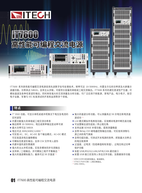
IT7600系列高性能可编程交流电源采用先进数字信号处理技术,频率可达波器功能。
功率高达54kVA,支持主从并联,可提供大容量的单相或三相交流输出。
IT7600模拟谐波及各种任意波形输出,同时具有强大的交流测量及分析功能,可广泛应用于新能源、家电产品、电力电子、航空电子设备、军事与IEC标准测试的开发和运用等多个领域。
强大的主从并机功能,实现多模块同步均流输出支持单/三相输出,并可模拟三相不平衡输出*2强大的谐波模拟能力,最高可达50次谐波*3保护功能标配USB/RS232/LAN/GPIB/CAN通讯接口前置USB接口实现导入导出文件功能,及数据保存功能*1 600V/1200V机型即将推出,敬请期待。
*2 IT7627/7628可单/三相切换输出。
*3 10Hz-500Hz。
IT7600 高性能可编程交流电源0102检测机构(GPS),电源的应用场合。
Current (A)IT7600 高性能可编程交流电源03Your Power Testing SolutionIT7600 高性能可编程交流电源可显示单机或者并机情况下电压及电流的实时波形IT7600系列高性能可编程交流电源拥有7 "超大的显示屏,提供强大的示波器功能。
内置高速采样量测电路,可显示实时电压及电流曲线,多机并联时,还可以同时显示所有并机的状态讯息,无需示波器就可以进行瞬时分析。
UPS IT8600 系列交直流电子负载7" DSO功能仿真交流电压与直流偏移电压IT7600系列高性能可编程交流电源具备仿真交流电压与直流偏移电压的功能,可以模拟任意波形输出。
可模拟任意波形输出04滤波器件是否超过了允许电流值。
反复开关环路,AC IT7600系列可以让用户自行设定电压或频率输出变动率,使电压或频率有规律的逐步达到设定值,可以更为精准的验证产品的操作范围,也可以减少待测物开机时的浪涌电流。
输出频率递增输出电压递增IT7600系列高性能可编程交流电源可以实现AC、DC、AC+DC 各个输出模式,不但可以提供纯正的交/直流输出、还提供AC+DC 输出模式来扩大应用,测试直流偏压成份。
IT6800系列 直流可编程电源 用户使用手册说明书

版权归属于艾德克斯电子(南京)有限公司Ver2.0/Jan, 2010/ IT6800-603用户使用手册直流可编程电源本使用手册适用于下列机型型号 IT6821 IT6822 IT6823 IT6831 IT6832 IT6833 IT6834IT6800系列目录前面板介绍 (5)功能按键说明 (5)菜单操作 (5)VFD指示灯功能描述 (6)背面板介绍 (6)第一章 快速入门 (7)1.1 预先检查 (7)1. 验货 (7)2.接上电源线并打开电源 (7)3.系统自检 (7)1.2 输出检查 (8)输出电压检查 (8)输出电流检查 (8)1.3 如果电源供应器不能启动 (8)1.4 电源把柄的调节方法 (9)1.5 电源上架操作 (10)第二章 技术规格 (11)2.1 主要技术参数 (11)2.2 补充特性 (11)第三章 面板操作 (13)3.1 前面板操作介绍 (13)3.2 定电压设置操作 (14)3.3 定电流设置操作 (14)3.4 存取操作 (15)3.5 菜单操作 (15)电压上限设置(>MAX VOLT) (15)电源上电后输出状态设定(>INIT OUT) (15)电源上电后输出电压设定(>INIT VOLT) (15)键盘发声设置(>KEY SOUND) (15)通讯波特率设置(>BAUD RATE) (16)通讯地址设置(>ADDR) (16)功能按键密码设置(>KEY LOCK) (16)第四章 远端操作模式 (17)4.1通讯模块简介 (17)4.2 电源与PC间的通讯 (18)2安全请勿自行在仪器上安装替代零件,或执行任何未经授权的修改。
请将仪器送到本公司的维修部门进行维修,以确保其安全特性。
请参考本手册中特定的警告或注意事项信息,以避免造成人体伤害或仪器损坏。
仪器内部并无操作人员可维修的部件,需维修服务,请联络受过训练的维修人员。
SIM7600E -H 4G HAT 用户手册说明书
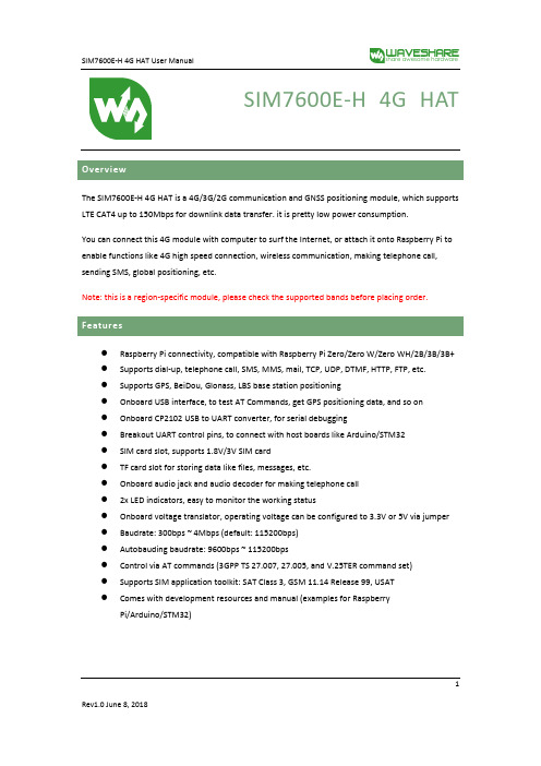
SIM7600E-H 4G HATThe SIM7600E-H 4G HAT is a 4G/3G/2G communication and GNSS positioning module, which supports LTE CAT4 up to 150Mbps for downlink data transfer. it is pretty low power consumption.You can connect this 4G module with computer to surf the Internet, or attach it onto Raspberry Pi to enable functions like 4G high speed connection, wireless communication, making telephone call, sending SMS, global positioning, etc.Note: this is a region-specific module, please check the supported bands before placing order.⚫Raspberry Pi connectivity, compatible with Raspberry Pi Zero/Zero W/Zero WH/2B/3B/3B+ ⚫Supports dial-up, telephone call, SMS, MMS, mail, TCP, UDP, DTMF, HTTP, FTP, etc.⚫Supports GPS, BeiDou, Glonass, LBS base station positioning⚫Onboard USB interface, to test AT Commands, get GPS positioning data, and so on⚫Onboard CP2102 USB to UART converter, for serial debugging⚫Breakout UART control pins, to connect with host boards like Arduino/STM32⚫SIM card slot, supports 1.8V/3V SIM card⚫TF card slot for storing data like files, messages, etc.⚫Onboard audio jack and audio decoder for making telephone call⚫2x LED indicators, easy to monitor the working status⚫Onboard voltage translator, operating voltage can be configured to 3.3V or 5V via jumper ⚫Baudrate: 300bps ~ 4Mbps (default: 115200bps)⚫Autobauding baudrate: 9600bps ~ 115200bps⚫Control via AT commands (3GPP TS 27.007, 27.005, and V.25TER command set)⚫Supports SIM application toolkit: SAT Class 3, GSM 11.14 Release 99, USAT⚫Comes with development resources and manual (examples for RaspberryPi/Arduino/STM32)1Note: Does not contain Raspberry PiCommunications SpecificationsGNSS Specifications⚫Receiver type◼16-channel◼C/A code2⚫Sensitivity◼Tracking: -159 dBm (GPS) / -158 dBm (GLONASS) / TBD (BD)◼Cold starts: -148 dBm⚫Time-To-First-Fix (open air)◼Cold starts: <35s◼Hot starts: <1s⚫Accuracy◼Position: <2.5m CEP⚫SMS◼Supported types: MT, MO, CB, Text, PDU◼Storage: USIM card and ME (default)⚫Audio feature◼Supports echo cancellation◼Supports noise reduction⚫Power supply: 5V⚫Operating voltage: 5V/3.3V (configured via jumper)⚫Operating temperature: -30°C ~ 80°C⚫Storage temperature: -45°C ~ 90°C⚫Dimension: 56.21mm x 65.15mm31.SIM7600E-H2.CP2102 USB to UART converter3.NAU8810 audio decoder4.TXS0108EPWR voltage translator: translates 3.3V/5V into 1.8V5.MP2128DT power chip6.MP1482 power chip7.Raspberry Pi GPIO header: for connecting with Raspberry Pi8.SIM7600 control interface: for connecting with host boards like Arduino/STM329.SIM card slot: supports 1.8V/3V SIM card10.TF card slot: allows file/SMS/... storage11. 3.5mm earphone/mic jackB interface: for testing AT Commands, getting GPS positioning data, etc.B to UART interface: for serial debugging, or login to Raspberry Pi14.MAIN antenna connector15.AUX antenna connector16.GNSS antenna connector17.Power switchwork status indicator19.Power indicator20.Operating voltage selection jumper:VCCIO - 3.3V: set operating voltage as 3.3VVCCIO - 5V: set operating voltage as 5V421.UART selection jumper:A: access Raspberry Pi via USB to UARTB: control the SIM7600 by Raspberry PiC: control the SIM7600 via USB to UART5Overview (1)Features (1)Communications Specifications (2)GNSS Specifications (2)SMS and Audio Specifications (3)Other Specifications (3)What's on Board (3)1.Hardware configuration (8)1.1.Hardware configuration (8)2.At Test Instructions (9)2.1.General AT commands (9)2.2.Make calls and answer calls (10)2.3.Send and receive messages (11)2.4.GPS Debugging (13)2.5.TF Card Test (15)2.6.GPRS Debugging (16)Local virtual severs settings (16)GPRS Test (17)ing with Raspberry Pi (18)3.1.Interface overview (18)3.2.UART configuration of Raspberry Pi (18)3.3.Init the Raspberry Pi (19)63.4.Minicom for UART debugging on Raspberry Pi (20)3.5.Examples (21)3.5.1.PhoneCall (21)3.5.2.SMS (22)3.5.3.GPS (22)3.5.4.TCP (23)3.5.5.FTP (23)ing with Arduino (24)4.1.Interface overview (24)4.2.Install Arduino Library (24)4.2.1.Phonecall (25)4.2.2.SMS (25)4.2.3.GPS (26)4.2.4.TCP (27)4.2.5.FTP (27)71.1.1.Hardware configurationThis module comes with GSM antenna, LTE antenna and micro USB cable. Besides these you should prepare a 4G sim card and a microphone cable with microphone:1)Insert the SIM card to the card slot, Insert the headphone cable and connect the LTE antenna.2)Connect the USB interface of SIM7600E-H 4G HAT to PC with a micro USB cable. Then the PWRindicator will keep bright.3)Press the PWRKEY button and hold for 1s, the NET indicator will blink as below. Generally, theNET indicator will fast flash firstly (1 time per second), which means that the module has not logged in the Network. After logging in, the indicator become to flash slowly (1 time every three seconds). Up to the local LTE network, this process that logging in will last several seconds to dozens of seconds.\If you take too much time to log in and failed, please check that whether the LTE antenna isconnected correctly, and whether the SIM card is usable and insert correctly.4)Install SIM7600 driver (windows driver: /wiki/File:SIM7X00-Driver.7z)Open Device Manager to get the corresponding COM port number of SIM7600. For example, the AT Port is COM19 as below. Users need to choose the correct port according to the Manager.Figure: Devices Manager82.At Test Instructions2.1.General AT commands910For more details, please refer to the documentation :Series_AT Command Manual_V1.072.2. Make calls and answer calls1) Insert the SIM card, connect the LTE antenna and connect the USB interface of SIM7600E-H 4G HAT to PC . Then press the PWRKEY to power on the board;2) Check whether the indicators blink correct ly (PWR’s and NET’s flashes).3)Send AT commands as bellow:ATA Call answer OK2.3.Send and receive messages1.Plug the SIM card, connect the LTE antenna and and c onnect the USB interface ofSIM7600E-H 4G HAT to PC. Then press the PWRKEY to power on the board;2.Check whether the indicators blink correct ly (PWR’s and NET’s flashes).3.Send AT commands as bellow:11122.4.GPS Debugging1)Connecting the GPS antenna, and place the receiver on open area outdoor2)AT+CGPS =1 //Turn on power of GPS3)Open u-center and set the Port and Baudrate (NMEA Port,COM27)4)AT+CGNSINF // Print the GPS information5)AT+CGPS =0 //Turn off power of GPS13142.5.TF Card Test1.Plug the SIM card, connect the LTE antenna and and c onnect the USB interface ofSIM7600E-H 4G HAT to PC. Then press the PWRKEY to power on the board;2.Check whether the indicators blink correct ly (PWR’s and NET’s flashes).3.Send AT commands as bellow:15162.6.GPRS DebuggingVirtual servers define the mapping between service ports of WAN and web servers of LAN. All requests from Internet to service ports of WAN will be redirected to the computer (web servers of LAN) specified by the server IP. (see your router’s guide manual)4)Log in Management Console of your router with browser (read your router’s guide manual forspecific address) 5)Set Port :1822 (The Port can ’t be conflict to other ’s. Here we set 1822)Set LAN IP address of your computer (you can run CMD on your computer, and execute command ipconfig to enquiry the address of IPv4), 192.168.6.168 as examples6)You can search “IP” on browser to get your WAN IP address.1.Plug the SIM card, connect the LTE antenna and and c onnect the USB interface ofSIM7600E-H 4G HAT to PC. Then press the PWRKEY to power on the board;2.Check whether the indicators blink correct ly (PWR’s and NET’s flashes).3.Send AT commands as bellow:17ing with Raspberry Pi3.1.Interface overviewThe default relationship between SIM7600 control pins and Raspberry Pi IOs is shown in Table 1. Table 1: The relationship between SIM7600 control pins and Raspberry Pi IOs3.2.UART configuration of Raspberry PiBecause UART of Raspberry Pi is used for Linux console output by default, if we want to use the UART, we need to change the settings. Executing this command to enter the configuration page :1819Open /boot/config.txt file, find the below statement and uncomment it to enable the UART. You can directly append it at the end of file as well.Then reboot.3.3. Init the Raspberry Pi1、Download the raspberry pi demo code and copy the SIM7600X folder to /home/pi/ directory. 2、 Enter /home/pi/ directory,execute command:3、 Open the /etc/rc.local file, then add the context below:203.4. Minicom for UART debugging on Raspberry PiInserting the module to Raspberry Pi and plug the jumper B,Install minicom ,minicom is a text-based modem control and terminal emulation program for Linux :Execute command:ttyS0 is the UART of Raspberry Pi 3B) Baud rate is 115200 by default. If you need to change the baud rate, for example 9600, you can add the parameter -b 9600.The user UART device of Raspberry Pi 2B/Zero is ttyAMA0, and ttyS0 of Raspberry Pi 3B Testing Bluetooth function as examples:213.5. Examples1、Download the demo code from wiki and copy to the Raspberry Pi (/home/pi/SIM7600X) 2、Enter the bcm2835 directory, compile and install the BCM2835 library:4、 Compile and run the demo (for example:PhoneCall): Clean up: sudo make clean Recompile: sudo makeRun the program: sudo ./PhoneCallCombination command: sudo make clean && sudo make && sudo ./PhoneCall2223ing with Arduino4.1.Interface overviewThe default relationship between SIM7600 control pins and Arduino is shown in Table 1.Table 2: The relationship between SIM7600 control pins and Arduino4.2.Install Arduino Library1.Download the Arduino demo code and copy the Waveshare_SIM7600X_Arduino_Library folderto {the Arduino software installation path}/Library/ .2.Run the Arduino IDE, then select the example code as below:244.2.1.PHONECALL254.2.3.GPS262728。
日立7600操作手册

日立7600操作手册摘要:一、日立7600 操作手册简介1.日立7600 操作手册的作用2.日立7600 操作手册的主要内容二、操作前的准备工作1.确保安全的工作环境2.检查设备的状态3.准备工作材料三、设备的基本操作1.设备的开启与关闭2.设备的主要功能介绍3.设备的基本参数设置四、设备的进阶操作1.高级功能的使用方法2.设备参数的详细设置3.常见问题的处理方法五、设备的维护与保养1.日常维护注意事项2.定期保养的方法3.故障排除与处理六、操作手册的使用建议1.针对不同用户群体的使用建议2.提高操作效率的技巧3.操作手册的更新与升级正文:日立7600 操作手册是针对日立7600 型号设备的使用指南,旨在帮助用户了解设备的基本操作、进阶操作以及维护保养等方面的知识。
通过阅读并理解操作手册,用户可以充分发挥设备的性能,提高工作效率,确保设备的安全使用。
在操作设备之前,务必确保工作环境的安全,避免在潮湿、高温或易燃易爆的环境中使用设备。
同时,检查设备的状态,确保设备各部件无损坏,电源线连接正常。
另外,根据需要准备好工作材料,以保证操作过程的顺利进行。
设备的基本操作包括设备的开启与关闭、设备的主要功能介绍以及设备的基本参数设置。
在开启设备前,请确保电源线已连接好,并打开设备电源开关。
设备的主要功能包括各种加工操作,用户可根据实际需求选择相应的功能。
设备的参数设置涉及到加工过程的诸多方面,如加工速度、加工深度等,用户应根据实际需求进行合理设置。
设备的进阶操作涉及到高级功能的使用方法、设备参数的详细设置以及常见问题的处理方法。
高级功能的使用需要用户对设备的基本操作有一定了解,同时熟悉设备参数的调整方法。
在操作过程中遇到问题时,可参考操作手册中的故障排除与处理部分,找到相应的解决方案。
设备的维护与保养对于设备的正常运行至关重要。
在日常使用过程中,应定期检查设备的状态,保持设备清洁,避免过度磨损。
此外,还要定期进行设备的保养,包括更换易损件、检查设备各部件的连接情况等。
Dell EqualLogic FS7600 系列设备硬件用户手册说明书

硬件用户手册© 版权所有 2011-2013 Dell Inc. 保留所有权利。
Dell™ 和 EqualLogic® 是 Dell Inc. 的商标。
本文使用的所有商标和注册商标均属其各自所有者的财产。
本说明文件中的信息如有更改,恕不另行通知。
未经 Dell 书面许可,严禁以任何形式进行复制。
发布时间:2013 年 10 月部件号:110-6178-ZH-CN R1目录前言v1 基本设备信息1设备组件1设备前面板功能部件1设备背面板功能部件2将设备连接至电源4打开和关闭电源5关闭控制器电源6打开控制器电源6所需工具6技术规格62 更换组件9安全建议9所需工具9使用防静电腕带9更换控制器10卸下控制器10安装控制器11安装 SFP+ 收发器12更换电源设备12卸下电源设备12安装电源设备12卸下挡板13连接挡板14更换散热风扇14卸下风扇14安装风扇16更换设备16卸下设备16安装设备17返还故障硬件173 下一步操作19NAS 群集文档19附录 A: NOM 信息(仅限于墨西哥)21词汇表23索引25iiiDell EqualLogic FS7600硬件用户手册目录iv前言Dell™ EqualLogic® FS Series 设备与 PS Series 阵列相结合,提供高性能、高可用性、可扩展的 NAS 解决方案。
本手册介绍如何对 EqualLogic FS7600 设备的客户可更换组件进行维护和故障排除。
读者对象本指南中的信息适用于负责维护 EqualLogic FS7600 硬件的硬件管理员。
相关说明文件有关 FS Series 设备、PS Series 阵列、组、卷、阵列软件以及主机软件的详情,请登录到位于客户支持站点的说明文件页。
Dell 联机服务您可以使用以下步骤了解 Dell 产品和服务:1. 访问或在任何 Dell 产品信息中指定的 URL。
2. 使用地区菜单或单击指定您所在国家/地区或区域的链接。
普传科技PI7800_7600系列使用说明书
前言感谢您选用普传科技PI7800、PI7600家族变频调速器。
PI7800、PI7600为PI7000、PI7600变频器的升级产品。
本产品是普传公司积多年专业生产销售经验和市场需求而设计的一系列适合在各种产业机械及风机水泵驱动控制及中频研磨重负荷使用的变频调速器。
本说明书包括PI7800和PI7600家族通用型和专用型两个系列,其中通用机型按负载大小分为F、G、M和H型,专用型分为S、T和Z 型,具体说明如下:F型:轻型负载G型:标准负载M型:较重负载H型:重型负载S型:纺织机专用型T型:提升机专用型Z型:注塑机专用型本说明书提供给用户安装、运行参数设定、异常诊断、日常维护及安全使用等相关注意事项。
为了保证正确地安装及操作本变频调速器,请在装机之前,详细阅读本使用说明书。
如在使用过程中还存在疑难问题,请联络本公司的各地经销商或直接与本公司联系,我们的专业人员乐于为您服务。
请将此说明书交给最终用户手中,希望用户妥善保管本说明书,这对今后的维护、保养以及其它应用的场合会有所俾益。
如在保修期间内发生问题,请填写保修卡后传真给经销商或本公司。
本产品在改进的同时,资料可能有所变动,恕不另行通知。
本公司其他产品资料请查阅网页:http:// 。
普传科技有限公司2008年1月目录第一章检查与安全注意事项 (1)第二章安装及备用电路 (3)第三章操作键盘 (15)第四章试运行 (19)第五章功能参数一览表 (20)第六章功能参数说明 (32)第七章异常诊断与处理 (79)第八章标准规范 (81)第九章保养与检修 (94)第十章选件 (96)第十一章品质保证 (100)附录1 RS485通信协议 (101)附录2 PG卡使用说明 (111)附录3 变频供水控制器使用说明 (115)第一章 检查与安全注意事项普传变频器在出厂之前均已经过测试和品质检验。
在购买后,请先检查产品的包装是否因运输不慎而造成损伤;产品的规格、型号是否与订购之机种相符。
高达1000V的交流电测试及全球标准电压供电模拟

高达1000V的交流电测试及全球标准电压供电模拟自特斯拉发明交流电以来,交流电成为了发电、输电及用电的主流形式。
由于各国电力系统的发展历史不同,电网所采用的电压参数也有所不同。
当然更高的电压值,在传输相同的电能时,意味着更小的电流及更小的损耗,也就能达到更远的输电距离。
但同时高电压对于相关设备的绝缘及耐压也有更高的要求,一旦发生事故,危险性也更大。
所以各国用电条件的不同,也影响了当地电网电压等级的演变。
国际电工委员会发布的标准文件《IEC 60038-2009 标准电压》中,对100V-1000V交流电系统常用电压值进行了规范,包括120/208、230、230/400、277/480、347/600、400/690、1000等,频率有些采用50Hz或60Hz(标注一个值的,为线电压,标注为两个值的,较低的是相电压,较高的是线电压)。
此标准中依据全球常用电压等级进行了简化,例如230/400 V此参数同时覆盖了相近的220/380 V及240/415 V。
1000V以下交流电系统一般被认为是低压系统并用于民用、工业用电等系统终端的用电环节。
具体来说,230/400V及以下电压等级一般用于家用用电,超过230/400V的常用于工业及大型商业楼宇。
这些系统中既包含有电动机、空调、照明等用电负荷,又包含有断路器、熔断器等开关保护设备及接触器、变频器等控制设备的广泛使用。
在这些产品的研发、生产、测试环节,都需要使用测试用交流电源来建立纯净稳定的测试环境,并按照其额定电压等级,完成相关标准化测试。
我们可以看到,在低压额定电压中,最大相电压高达400V,线电压高达1000V,但是市面上很难找到如此高电压的交流可编程电源,许多设备厂家都无法进行满电压测试,或者只能使用变压器来改变电压而使得测试流程难以操作。
300V以上用电环境模拟1、煤矿、化工、船舶在煤矿中进行供电时面临着输电距离远、用电负荷大的问题,民用300V以下的供电电压难以提供充足的动力,所以在中国,煤矿电源采用更高一级的三相660V电压。
ProSAFE 无线控制器 WC7600 用户手册
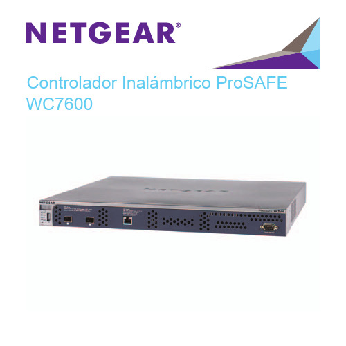
Controlador Inalámbrico ProSAFE WC7600Contenido de la cajaEl paquete contiene los siguientes elementos:•Controlador inalámbrico ProSAFE® Wireless Controller WC7600•Cable de alimentación de CA•Cable Ethernet de categoría 5 de conexión directa•Kit de montaje en bastidor•Patas de goma (4), cuya parte posterior es adhesiva•Guía de instalaciónADVERTENCIA:NO coloque los dispositivos uno encima del otro (en una pila), ni en espacios reducidos o cajones. Asegúrese de que hay un espacio libre de al menos 5 cm alrededor del equipo para que ventile.Conozca su controlador inalámbrico Antes de instalar el controlador inalámbrico, familiarícese con los indicadores, botones y puertos.Panel frontalPower (Encendido), Status (Estado),Fan (Ventilador), Stack Master (Dispsitivo principal de pila)Panel posteriorIndicador del estado de la alimentaciónEntrada de la fuente de alimentaciónConfiguración del controladorinalámbricoCómo configurar el controlador inalámbrico:1.Configure el equipo con la dirección IP estática 192.168.0.210 yla máscara de subred 255.255.255.0.2.Conecte un extremo del cable Ethernet proporcionado al puertoEthernet del equipo y el otro extremo al puerto Ethernet delpanel frontal del controlador inalámbrico.3.Conecte el cable de alimentación proporcionado del controladorinalámbrico a una toma de corriente de CA.pruebe que se encienden los siguientes indicadores en elpanel frontal:Indicador DescripciónEntrada de la fuente de alimentación El indicador de encendido verde está iluminado. En caso contrario, compruebe las conexiones y cualquier interruptor en la toma de corriente que pudiera estar apagado.Estado El indicador de estado se ilumina en amarillo mientras el controlador inalámbrico se está inicializando.Después de aproximadamente dos minutos, cuando elcontrolador inalámbrico ha completado su inicialización,el indicador de estado se ilumina en verde. Ventilador El indicador de ventilador verde está encendido, lo que indica que los ventiladores están funcionandocorrectamente.Puerto Ethernet El indicador de puerto Ethernet de la derecha se ilumina en verde para una conexión de 1000 Mbps o en amarillo para una conexión de 100 ó 10 Mbps.Acceso al controlador inalámbricoPara obtener acceso al controlador inalámbrico:1.En el equipo, abra una ventana del navegador. En el campo dedirección, escriba http://192.168.0.250.Se muestra la pantalla de inicio de sesión del controladorinalámbrico:2.Introduzca admin como nombre de usuario y password comocontraseña (utilice minúsculas en ambos casos).3.Haga clic en el botón Login (Iniciar sesión).Se muestra la interfaz de gestión web del controladorinalámbrico.Configuración básicaPara configurar las opciones básicas:1.Desde el menú de navegación principal, seleccioneConfiguration (Configuración) > System (Sistema) > General (General).2.Introduzca un nombre para el controlador inalámbrico.3.Seleccione el país en el que se utiliza el controlador inalámbrico.4.Haga clic en el botón Apply (Aplicar).5.Seleccione Configuration (Configuración) > System (Sistema) >Time (Hora).6.Seleccione la zona horaria en la que se utiliza el controladorinalámbrico.7.(Opcional) Configure las opciones de NTP.8.Haga clic en el botón Apply (Aplicar).9.Seleccione Configuration (Configuración) > System (Sistema) >IP/VLAN.10.Introduzca la configuración de IP de la red y las VLAN quedesea asignar al controlador inalámbrico.Nota: Para grandes instalaciones, NETGEAR recomiendaque el controlador inalámbrico y los puntos de acceso esténen VLAN independientes para garantizar una conectividadsin interrupciones entre el controlador inalámbrico y lospuntos de acceso.Nota: Desactive la casilla Untagged VLAN (VLAN sinetiquetas) sólo si los concentradores y conmutadores de lared son compatibles con el estándar VLAN (802.1Q). Cambieel valor de VLAN sin etiquetar sólo si los concentradores yconmutadores de la red son compatibles con el estándarVLAN (802.1Q).11.Haga clic en el botón Apply (Aplicar).La conexión al controlador inalámbrico ha terminado porque ha cambiado su dirección IP.12.Vuelva a configurar el equipo con una dirección IP y unamáscara de subred que se encuentren en la misma subred IP que el controlador inalámbrico. Utilice la nueva dirección IP del controlador inalámbrico para iniciar una nueva sesión.13.Seleccione Configuration (Configuración) > System (Sistema) >DHCP Server (Servidor DHCP). El asistente para la detección (consulte Detección de puntos de acceso) necesita un servidor DHCP para detectar los puntos de acceso. Si ya dispone de un servidor DHCP en la red, desactive el servidor DHCP en elcontrolador inalámbrico. De lo contrario, configure los ajustes DHCP para el servidor DHCP en el controlador inalámbrico.14.Haga clic en Apply (Aplicar).15.Determine si desea utilizar el grupo de perfiles básicos (aptopara una WLAN pequeña) o uno o más grupos de perfilesavanzados (apto para una WLAN grande):•Basic (Básico). Permite hasta ocho perfiles (16 puntos de acceso de banda dual), cada uno de los cuales tiene supropio SSID, seguridad, ACL de MAC, configuración delimitación de velocidad, ajustes WMM, etc.a.Seleccione Configuration (Configuración) > Profile(Perfil) > Basic (Básico) > Radio (Radio).b.Configure uno o más perfiles, cada uno con suconfiguración de SSID y de seguridad.c.Haga clic en el botón Apply (Aplicar).•Advanced (Avanzado). Permite hasta ocho grupos de perfiles. Cada grupo incluye todos los ajustes que sonnecesarios para configurar un punto de acceso totalmentefuncional con hasta ocho perfiles de seguridad (16 puntos deacceso de banda dual).a.Seleccione Configuration (Configuración) > Profile(Perfil) > Advanced (Avanzado) > Radio (Radio).b.Configure uno o más grupos de perfiles, cada uno conuno o más perfiles con su propia configuración de SSID yde seguridad.c.Haga clic en el botón Apply (Aplicar).Nota: Para obtener más información sobre las opciones de configuración del controlador inalámbrico, incluidos los grupos de perfiles, consulte el manual de referencia.Instalación del controlador inalámbrico Para instalar el controlador inalámbrico:1.Desconecte el cable de alimentación del controladorinalámbrico.2.Desconecte el controlador inalámbrico del equipo y sitúelodonde desee instalarlo.3.Conecte un extremo de un cable Ethernet a un puerto LAN enun router o conmutador de la red y el otro extremo al puertoEthernet del panel frontal del controlador inalámbrico.4.Vuelva a conectar el cable de alimentación desde el controladorinalámbrico a una toma de corriente de CA.Los indicadores se iluminan como se describe en Configuración del controlador inalámbrico.Detección de puntos de accesoEl controlador inalámbrico gestiona los puntos de acceso de NETGEAR seleccionados. Para obtener una lista de los puntos de acceso de NETGEAR compatibles, visite el sitio web de asistencia técnica de NETGEAR.Antes de intentar detectar puntos de acceso, familiarícese con los indicadores de los puntos de acceso:Indicador DescripciónEntrada de la fuente de alimentación El indicador de alimentación verde parpadea cuando el punto de acceso se enciende por primera vez y, a continuación, se ilumina de color verde fijo. Si pasados 30 segundos el indicador de encendido no está iluminado o aún parpadea, compruebe las conexiones y si algún interruptor de la toma de corriente que está apagado.Indicador de actividad El indicador de actividad parpadea cuando el punto de acceso detecta tráfico de red.LAN Verde. Velocidad de conexión de 1000 Mbps.Ámbar. Velocidad de conexión de 10/100 Mbps.Apagado. No se detecta la conexión.2,4 GHz Tráfico de 2,4 GHz en la WLAN.5 GHz Tráfico de 5 GHz en la WLAN.El asistente para la detección puede detectar puntos de acceso que se encuentren en estado predeterminado de fábrica o ya instalados y en funcionamiento. Para que el asistente para la detección detecte puntos de acceso a través de una red de capa 2, red de capa 3 (detrás de un router) o puntos de acceso remoto, se tienen que cumplir los siguientes requisitos:•La red debe disponer de un servidor DHCP que tenga la opción43 activada con la dirección IP del controlador inalámbrico, o elservidor DHCP del controlador inalámbrico debe ser accesible para todos los puntos de acceso.•Cada punto de acceso debe tener una dirección IP.•Cada punto de acceso debe tener SNMP y SSH activado (que es el valor predeterminado).•El cortafuegos debe desbloquear el número de puerto UDP 7890. Para detectar puntos de acceso de:1.Acceda al controlador inalámbrico en la dirección IP de red queha configurado (consulte Configuración básica).2.Seleccione Access Point (Punto de acceso) > Discovery(Detección) > Discovery Wizard (Asistente de detección).3.Siga los pasos que aparecen en pantalla para detectar lospuntos de acceso y revise los resultados de la detección.4.Seleccione Access Point (Punto de acceso) > Discovery(Detección) > Managed AP List (Lista de PA gestionados).Agregue los puntos de acceso que desee que gestione elcontrolador inalámbrico a la lista de puntos de accesogestionados.Aunque los puntos de acceso se convierten de modo autónomo a modo gestionado, ocurre lo siguiente:•El controlador inalámbrico inserta el firmware de gestión en los puntos de acceso.•Los puntos de acceso se convierten en clientes DHCP y reciben una dirección IP del servidor DHCP en la red o del servidorDHCP en el controlador inalámbrico.•Los perfiles que ha configurado en el controlador inalámbrico se insertan en los puntos de acceso.Nota: Para obtener más información sobre el asistente para la detección y el proceso de detección, consulte el manual de referencia.Solución de problemasNo se puede acceder al controlador inalámbrico en su dirección IP predeterminada (192.168.0.250). Realice las siguientes acciones:•Compruebe que el equipo esté conectado a un controlador inalámbrico.•Puede que no haya reiniciado el equipo con el controlador inalámbrico para que se apliquen los cambios de TCP/IP.Reinicie el ordenador.•El equipo puede estar configurado para activar NetBIOS a través de TCP/IP. Compruebe que TCP/IP está configurado para utilizar una dirección IP estática de 192.168.0.210 y una máscara desubred 255.255.255.0. (La configuración TCP/IP predeterminada para Windows es obtener una dirección IP automáticamente.) Reinicie el ordenador.Después de la configuración inicial, no se puede acceder al controlador inalámbrico en su propia dirección de red. Realice las siguientes acciones:•Utilice el comando ping para comprobar la conexión.•Compruebe que el equipo y el controlador inalámbrico están en la misma VLAN.•Puede que alguna configuración predeterminada del controlador inalámbrico no funcione con la red. Compruebe la configuración predeterminada del controlador inalámbrico comparándola con la del resto de dispositivos de la red.SoporteGracias por elegir un producto NETGEAR. Una vez instalado el dispositivo, busque elnúmero de serie en la etiqueta del producto y regístrelo en https://.Deberá registrar su producto para poder hacer uso de nuestro servicio telefónico de asistencia NETGEAR. NETGEAR recomienda registrar su producto a través del sitio web de NETGEAR.Encontrará actualizaciones del producto y asistencia técnica en . NETGEAR le recomienda que utilice solo los recursos del servicio técnico oficial de NETGEAR. Puede ponerse en contacto con los representantes del servicio técnico de NETGEAR a través de chat, correo electrónico o asistencia telefónica en/general/contact/default.aspx.Marcas comercialesNETGEAR, el logotipo de NETGEAR y Connect with Innovation son marcas comerciales o marcas comerciales registradas de NETGEAR, Inc. o sus filiales en Estados Unidos y otros países. La información contenida en el documento puede sufrir modificaciones sin previo aviso. © NETGEAR, Inc. Todos los derechos reservados.Cumplimiento normativoPara la declaración de conformidad actual de la UE, visite/app/answers/detail/a_id/11621/.Para obtener información sobre el cumplimiento de normativas, visite/about/regulatory/.NETGEAR, Inc.350 East Plumeria DriveSan José, CA 95134 Estados UnidosNoviembre de 2013。
可编程直流电源说明书CH

此模式输出迅速开始或者完成的时候用。
警告:当提供持续的电压到一个电感负载,你选择高速度模式的时候,装置将会因为相位旋转而震动。为了防止这样的情况发生,将平行面接到一个电路负载上(有一个电容器和一个电阻器串联组成)。如果这样的装置还不能解除振动,请选择常规状态。
如果一个高频率全电阻的电容器直接连接到一个输出接口上,当机器高速度运做的时候,装置将会因为负载的原因而震动。
·显示屏幕后灯没有亮、或者没有任何的显示信号
方法:确认一下AC输入电源线是否连接正确。接着再次打开POWER-ON开关。
·尽管灯有亮,但是没有任何的显示信号
方法:调节CONTRAST(依据温度进行调节)接着再次打开POWER-ON开关。
·尽管有一个指示箭头在屏幕上显示,但是没有任何的文字显示。
方法:如果有装转接板,那就移动转接板,接着再次打开POWER-ON开关。如果屏幕上有型号显示了,那就安装转接板,接着再次打开POWER-ON开关
㈠选择功能
当你按下功能键,在键上方将会有黑色的字体来显示功能供你来选择。
如果你想选择第二功能(字体下加蓝色的下横线),首先按SHIFT键,然后迅速检查一下LED是否有亮,然后按功能键。例如,如果你想选择RESET功能,那么你先按SHIFT键,然后再按ESC键。
㈡增加和减少数字值
输入的数字值可以通过数字值输入键或者是JOG/SHUTTLE来增加和减少。
·通过外壳A,夹紧电线
④将电线接到输入接口。
·电线的中心线颜色代码如下,确定正确的线连接到了正确的接口。
L:黑色或者是棕色
N:白色或者是蓝色
GND:绿色或者是绿色/黄色
螺丝钉在接口板的部分为4MM(M4)
⑤盖好接口盒
Cisco 7600 Series 路由器模块指南说明书
C H A P T E R2-1Cisco 7600 Series Routers Module GuideOL-9392-042Ethernet and Gigabit Ethernet Switching ModulesThis chapter describes the Ethernet and Gigabit Ethernet switching modules, and it contains these sections:•10/100 and 10/100/1000 Ethernet Switching Modules, page 2-1•Gigabit Ethernet Switching Modules, page 2-13•Ethernet Module LEDs, page 2-2110/100 and 10/100/1000 Ethernet Switching ModulesNoteSpecific combinations of supervisor engines and modules may not be supported in your chassis. Refer to the release notes for the software version running on your system for specific information on modules and supervisor engine combinations that are not supported.This section describes these 10/100 and 10/100/1000 Ethernet switching modules:•24-Port 10BASE-FL Ethernet Switching Module (WS-X6024-10FL-MT), page 2-4•48-Port 10/100/1000BASE-T Ethernet Switching Module (WS-X6148-GE-TX), page 2-4•48-Port 10/100/1000BASE-T Ethernet Switching Module (WS-X6148V-GE-TX), page 2-4•48-Port 10/100BASE-T Ethernet Switching Module (WS-X6148-RJ21V), page 2-5•48-Port 10/100BASE-T Ethernet Switching Module (WS-X6148-RJ45V), page 2-6•24-Port 100BASE-FX Ethernet Switching Module (WS-X6224-100FX-MT), page 2-6•48-Port 10/100BASE-T Ethernet Switching Module (WS-X6248-RJ45), page 2-7•48-Port 10/100BASE-T Ethernet Switching Module (WS-X6248-TEL), page 2-7•48-Port 10/100BASE-T Ethernet Switching Module (WS-X6248A-TEL), page 2-7•24-Port 100BASE-FX Ethernet Switching Module (WS-X6324-100FX-MM), page 2-8•24-Port 100BASE-FX Ethernet Switching Module (WS-X6324-100FX-SM), page 2-8•48-Port 10/100BASE-T Ethernet Switching Module (WS-X6348-RJ21V), page 2-9•48-Port 10/100BASE-T Ethernet Switching Module (WS-X6348-RJ-45), page 2-9•48-Port 10/100BASE-T Ethernet Switching Module (WS-X6348-RJ45V), page 2-10Cisco 7600 Series Routers Module GuideOL-9392-04Chapter 2 Ethernet and Gigabit Ethernet Switching Modules10/100 and 10/100/1000 Ethernet Switching Modules•24-Port 100BASE-FX Fabric-Enabled Ethernet Switching Module (WS-X6524-100FX-MM), page 2-10•48-Port 10/100/1000BASE-T Ethernet Switching Module (WS-X6548-GE-TX), page 2-11•48-Port 10/100/1000BASE-T Ethernet Switching Module (WS-X6548V-GE-TX), page 2-11•48-Port 10/100BASE-T Fabric-Enabled Ethernet Switching Module (WS-X6548-RJ-21), page 2-12•48-Port 10/100BASE-T Fabric-Enabled Ethernet Switching Module (WS-X6548-RJ-45), page 2-12•48-Port 10/100/1000BASE-T Fabric-Enabled Ethernet Switching Module (WS-X6748-GE-TX), page 2-13Table 2-1 lists the features of the Ethernet switching modules.T able 2-1Ethernet Switching Modules FeaturesProduct Number Backplane Connection Forwarding Inline Power 1Port Buffer Size Queues Per Port WS-X6024-10FL-MT 32 Gbps Bus Centralized No 128 KB 2 transmit,1 receive WS-X6148-GE-TX 32 Gbps Bus Centralized Optional 2128 KB 2 transmit,1 receive WS-6148V-GE-TX 32 Gbps Bus Centralized Yes 128 KB 2 transmit,1 receive WS-X6148-RJ21V 32 Gbps Bus Centralized Yes 128 KB 2 transmit,1 receive WS-X6148-RJ45V 32 Gbps Bus Centralized Yes 128 KB 2 transmit,1 receive WS-X6224-100FX-MT 32 Gbps Bus Centralized Yes 128 KB 2 transmit,1 receive WS-X6248-RJ-4532 Gbps Bus Centralized No 128 KB 2 transmit,1 receive WS-X6248-TEL 32 Gbps Bus Centralized No 128 KB 2 transmit,1 receive WS-X6248A-TEL 32 Gbps Bus Centralized No 128 KB 2 transmit,1 receive WS-X6324-100FX-MM 32 Gbps Bus Centralized No 128 KB 2 transmit,1 receive WS-X6324-100FX-SM 32 Gbps Bus Centralized No 128 KB 2 transmit,1 receive WS-X6348-RJ21V 32 Gbps Bus Centralized Yes 128 KB 2 transmit,1 receive WS-X6348-RJ-4532 Gbps Bus Centralized Optional 2128 KB 2 transmit,1 receive WS-X6348-RJ45V32 Gbps BusCentralizedYes128 KB2 transmit,1 receiveCisco 7600 Series Routers Module GuideOL-9392-04Chapter 2 Ethernet and Gigabit Ethernet Switching Modules10/100 and 10/100/1000 Ethernet Switching ModulesWS-X6524-100FX-MMSwitch Fabric and BusCentralized Supportsoptional DFC card No1 MB4 transmit,2 receiveWS-X6548-GE-TX Switch Fabric and Bus Centralized Optional 2 1 MB 4 transmit,2 receive WS-6548V-GE-TX Switch Fabric and Bus Centralized Yes 1 MB 4 transmit,2 receive WS-X6548-RJ-21Switch Fabric and BusCentralized Supportsoptional DFC card No1 MB4 transmit,2 receiveWS-X6548-RJ-45Switch Fabric and BusCentralized Supportsoptional DFC card No 1 MB4 transmit,2 receiveWS-X6748-GE-TXSwitch Fabric CEF720No 1.3 MB4 transmit,2 receive1.Supports IP phones.2.Supports an optional inline power field upgrade module (WS-F6K-VPWR=)T able 2-1Ethernet Switching Modules Features (continued)Product Number Backplane Connection Forwarding Inline Power 1Port Buffer Size Queues Per Port2-4Cisco 7600 Series Routers Module GuideOL-9392-04Chapter 2 Ethernet and Gigabit Ethernet Switching Modules10/100 and 10/100/1000 Ethernet Switching ModulesNote2-5Cisco 7600 Series Routers Module GuideOL-9392-04Chapter 2 Ethernet and Gigabit Ethernet Switching Modules10/100 and 10/100/1000 Ethernet Switching Modules2-6Cisco 7600 Series Routers Module GuideOL-9392-04Chapter 2 Ethernet and Gigabit Ethernet Switching Modules10/100 and 10/100/1000 Ethernet Switching ModulesNote2-7Cisco 7600 Series Routers Module GuideOL-9392-04Chapter 2 Ethernet and Gigabit Ethernet Switching Modules10/100 and 10/100/1000 Ethernet Switching Modules2-8Cisco 7600 Series Routers Module GuideOL-9392-04Chapter 2 Ethernet and Gigabit Ethernet Switching Modules10/100 and 10/100/1000 Ethernet Switching ModulesNoteNote2-9Cisco 7600 Series Routers Module GuideOL-9392-04Chapter 2 Ethernet and Gigabit Ethernet Switching Modules10/100 and 10/100/1000 Ethernet Switching Modules2-10Cisco 7600 Series Routers Module GuideOL-9392-04Chapter 2 Ethernet and Gigabit Ethernet Switching Modules10/100 and 10/100/1000 Ethernet Switching ModulesNote2-11Cisco 7600 Series Routers Module GuideOL-9392-0410/100 and 10/100/1000 Ethernet Switching Modules2-12Cisco 7600 Series Routers Module GuideOL-9392-0410/100 and 10/100/1000 Ethernet Switching Modules2-13Cisco 7600 Series Routers Module GuideOL-9392-04Gigabit Ethernet Switching ModulesCisco 7600 Series Routers Module GuideOL-9392-04Gigabit Ethernet Switching ModulesT able 2-2Gigabit and 10-Gigabit Ethernet Switching Modules FeaturesProduct Number Backplane Connection Forwarding Number of Transmit Queues/Port Number of Receive Queues/Port WS-X6316-GE-TX Bus Centralized 32WS-X6408-GBIC Bus Centralized 32WS-X6408A-GBIC Bus Centralized 32WS-X6416-GBIC Bus Centralized 32WS-X6416-GE-MT BusCentralized32WS-X6501-10GEX4Switch fabric and busCentralized. Support for distributed forwarding with optionaldistributed forwarding card (DFC)32WS-X6502 -10GESwitch fabric and bus Centralized. Support for distributed forwarding with optional DFC 32WS-X6516-GBIC Switch fabric and bus Centralized. Support for distributed forwarding with optional DFC 32WS-X6516A-GBIC Switch fabric and bus Centralized. Support for distributed forwarding with optional DFC 32WS-X6516-GE-TX Switch fabric and busCentralized. Support for distributed forwarding with optional DFC32WS-X6704-10GESwitch fabric 1(dual channel)1.The module can be installed in slots 2–6 in the Cisco 7606, slots 2–9 in the Cisco 7609 and OSR-7609, and slots 9–13 in the Cisco7613 routers. It cannot be installed in slots 2–8 of the Cisco 7613 router. The module requires a Supervisor Engine 720.Centralized. Support for distributed forwardingwith optional DFC 3222.Receive queues change depending on whether you have a centralized forward card (CFC) or a DFC. For information about queuestructures, see /en/US/docs/routers/7600/ios/12.2SXF/configuration/guide/qos.html#wp1673687.WS-X6724-SFPSwitch fabricCentralized. Support for distributed forwarding with optional DFC 322WS-X6748-SFP Switch fabricCentralized. Support for distributed forwarding with optional DFC322WS-X6816-GBIC Switch fabric 1 (dual channel)Distributed forwarding with integrated DFC 32WS-X6708-10G-3C Switch fabric Distributed forwarding with integrated DFC 882WS-X6708-10G-3CXLSwitch fabricDistributed forwarding with integrated DFC8822-15Cisco 7600 Series Routers Module GuideOL-9392-04Gigabit Ethernet Switching ModulesNoteNote2-16Cisco 7600 Series Routers Module GuideOL-9392-04Gigabit Ethernet Switching ModulesNoteNote2-17Cisco 7600 Series Routers Module GuideOL-9392-04Gigabit Ethernet Switching ModulesNote2-18Cisco 7600 Series Routers Module GuideOL-9392-04Gigabit Ethernet Switching ModulesNote2-19Cisco 7600 Series Routers Module GuideOL-9392-04Gigabit Ethernet Switching Modules2-20Cisco 7600 Series Routers Module GuideOL-9392-04Gigabit Ethernet Switching ModulesNoteNote2-21Cisco 7600 Series Routers Module Guide OL-9392-04T able2-3Ethernet and Gigabit Ethernet Module LEDs (continued)LED Color/State DescriptionOrange The module is booting or running diagnostics.An overtemperature condition has occurred. (A minor temperaturethreshold has been exceeded during environmental monitoring.)Red The module is resetting. The switch has just been powered on or themodule has been hot inserted during the normal initializationsequence.An overtemperature condition has occurred. (A major temperaturethreshold has been exceeded during environmental monitoring.)If the module fails to download code and configuration informationsuccessfully during the initial reset, the LED stays red; the moduledoes not come online.Off The module is not receiving power.Cisco 7600 Series Routers Module GuideOL-9392-04Cisco 7600 Series Routers Module Guide OL-9392-04LINK GreenThe port is active (the link is connected and operational).OrangeThe module or port is disabled through the CLI command or the module is initializing 1. FlashingorangeThe port is faulty and has been disabled.Off The port is not active or the link is not connected.PHONE Green The voice daughter card is installed.OffThe voice daughter card is not detected or is not installed.1.This is a good time to verify that all LINK LEDs are functioning.T able 2-3Ethernet and Gigabit Ethernet Module LEDs (continued)LEDColor/State DescriptionCisco 7600 Series Routers Module GuideOL-9392-04。
LEXMARK 7600系列 说明书

3
在 USB、以太网和无线连接之间转换(仅限于 Windows).....................................................49 在 USB、以太网和无线连接之间转换(仅限于 Macintosh 英文版)........................................51 高级无线设置............................................................................................................................53
在安装过程中允许使用软件......................................................................................................13 安装打印机(只用作复印机或传真机)....................................................................................13 了解打印机的部件.....................................................................................................................20 使用打印机操作面板按钮和菜单...............................................................................................22
7600 Series 用户手册
HP TFT7600机架式一体化键盘显示器用户指南

本文档适合那些安装机架和机架产品的人员使用。只有经过培训的人员才可执行此操作。HP 假定您有资格 执行安装,并接受过专门的培训,能够识别机架产品方面的危险。
目录
简介 ............................................................................................................................................ 5
亮度/对比度................................................................................................................................. 16 图像控制 ...................................................................................................................................... 16 高级 ............................................................................................................................................ 17 自动配置 ...................................................................................................................................... 18 出厂设置 ...................................................................................................................................... 18 语言 ............................................................................................................................................ 18 信息 ............................................................................................................................................ 18
ICOM IC-7600 中文说明书(完全版)

克风具有不同的引脚分配,如果连接到 IC-7600 可能 会损坏收发器或麦克风。
LCD 液晶显示器可能有出现深色或小光点瑕疵,这 不是故障或缺陷,而是一个正常的 LCD 显示器的特 点.
在海上移动操作时,使收发器和麦克风远离磁罗盘 导航医,以防止影响的正确的导航
❍ 高分辨率的频谱显示器,中心频率和固定频率模式,还有迷 你频谱显示.
❍ 前后面板上的 USB 控制接口. ❍ 大型液晶显示屏采用 LED 背光.
重要
仔细阅读操作说明书
在你尝试操作之前. 如果你发现错误,希望你告知我们及时改正。
保存操作说明书.
本手册包含 IC-7600 重要安全操作说明.
明确定义
文本
当连接到 [ACC 1] ........................................ 22
◇ AFSK 操作 ................................................. 22
◇ 当连接到 [USB] 接口……… ……………... 22
■ 麦克风连接器信息 .......................................... 23 ■ 麦克风............................................................. 23
随机配件
发射机附带以下附件.
Qty.
○1 手持话筒
........................................................ 1
○2 直流电源线 ............................................................ 1
t7600通讯手册
t7600通讯手册【原创版】目录1.T7600 通讯手册概述2.T7600 通讯手册的主要内容3.T7600 通讯手册的使用方法4.T7600 通讯手册的适用对象5.总结正文【T7600 通讯手册概述】T7600 通讯手册是一本详尽介绍 T7600 通讯设备使用方法和相关知识的指南,旨在帮助用户更好地理解和使用 T7600 通讯设备,提高通讯效率。
【T7600 通讯手册的主要内容】T7600 通讯手册主要包括以下内容:设备概述、设备基本操作、高级功能应用、故障排除与维护、操作实例等。
【设备概述】部分详细介绍了 T7600 通讯设备的主要性能参数、外观设计和接口布局,帮助用户对设备有一个全面的了解。
【设备基本操作】部分包括设备开启与关闭、基本通讯操作、通讯参数设置等,让用户掌握设备的基本使用方法。
【高级功能应用】部分介绍了如何使用 T7600 通讯设备的高级功能,如数据传输、远程控制、实时通讯等,以满足不同用户的需求。
【故障排除与维护】部分提供了设备可能出现的故障现象及解决方法,以及设备的日常维护和保养措施,保证设备的稳定运行。
【操作实例】部分通过具体的应用案例,帮助用户更好地理解和运用T7600 通讯设备。
【T7600 通讯手册的使用方法】用户在阅读 T7600 通讯手册时,应先了解设备的基本情况,然后逐步学习基本操作和高级功能应用。
在实际操作过程中,遇到问题可以参考故障排除与维护部分,进行自我排查和解决。
【T7600 通讯手册的适用对象】T7600 通讯手册适用于 T7600 通讯设备的所有用户,包括设备维护人员、操作人员和技术支持人员等。
通过学习本手册,用户可以熟练掌握T7600 通讯设备的使用方法,提高工作效率。
【总结】T7600 通讯手册是一本全面介绍 T7600 通讯设备的使用和维护的指南,对提高用户的操作技能和设备运行效率具有重要意义。
日立7600操作手册

日立7600操作手册(原创实用版)目录1.日立 7600 概述2.安装与设置3.操作方法4.维护与保养5.故障排除正文【日立 7600 概述】日立 7600 是一款性能卓越的设备,其设计紧凑,适用于各种环境。
该设备集成了多种功能,为用户提供了高效的解决方案。
本操作手册旨在帮助用户更好地了解和操作日立 7600。
【安装与设置】在安装日立 7600 之前,请确保设备放置在稳固且水平的地面上。
按照设备附带的安装指南进行安装。
安装完成后,进行相关设置,包括但不限于:语言、工作模式等。
确保所有设置符合实际需求。
【操作方法】日立 7600 的操作非常简便。
首先,打开设备电源,然后按照显示屏上的提示进行操作。
用户可以根据实际需求选择不同的功能模式。
在操作过程中,请遵循设备上的安全标识和操作规程。
【维护与保养】为了确保日立 7600 的正常运行和延长设备使用寿命,用户需要定期进行维护和保养。
主要包括:清洁设备、检查零部件、更换易损件等。
在使用过程中,注意观察设备的运行状况,如有异常,请及时进行处理。
【故障排除】在使用过程中,可能会出现一些故障。
遇到故障时,请先关闭设备电源,然后根据设备附带的故障排除指南进行排查。
如无法自行解决,请联系售后服务人员或专业维修人员进行处理。
请勿擅自拆卸设备,以免造成不必要的损失。
通过本操作手册的介绍,相信您对日立 7600 已经有了更加深入的了解。
在使用过程中,请遵循相关指南,确保设备安全、高效地运行。
ITECH IT6100 系列可程式直流电源使用手册
高速高精度可程式設計直流電源IT6100系列使用者手冊型號:IT6151/IT6152/IT6153/IT6154/IT6162/IT6163/IT6164版本號:V3.0聲明© Itech Electronic, Co., Ltd. 2019根據國際版權法,未經Itech Electronic, Co., Ltd. 事先允許和書面同意,不得以任何形式(包括電子存儲和檢索或翻譯為其他國家或地區語言)複製本手冊中的任何內容。
手冊部件號IT6100-402196版本第3版,2019 年03 月8 日發佈Itech Electronic, Co., Ltd.商標聲明Pentium是Intel Corporation在美國的注冊商標。
Microsoft、Visual Studio、Windows 和MS Windows是Microsoft Corporation 在美國和/或其他國家/地區的商標。
擔保本文檔中包含的材料“按現狀”提供,在將來版本中如有更改,恕不另行通知。
此外,在適用法律允許的最大範圍內,ITECH 不承諾與本手冊及其包含的任何資訊相關的任何明示或暗含的保證,包括但不限於對適銷和適用於某種特定用途的暗含保證。
ITECH對提供、使用或應用本文檔及其包含的任何資訊所引起的錯誤或偶發或間接損失概不負責。
如ITECH與使用者之間存在其他書面協議含有與本文檔材料中所包含條款衝突的保證條款,以其他書面協議中的條款為准。
技術許可本文檔中描述的硬體和/或軟體僅在得到許可的情況下提供並且只能根據許可進行使用或複製。
限制性許可權聲明美國政府限制性許可權。
授權美國政府使用的軟體和技術資料許可權僅包括那些定制提供給最終用戶的許可權。
ITECH 在軟體和技術資料中提供本定制商業許可時遵循FAR 12.211(技術資料)和12.212(電腦軟體)以及用於國防的DFARS252.227-7015(技術資料-商業製品)和DFARS 227.7202-3(商業電腦軟體或電腦軟體文檔中的許可權)。
ITECH直流可编程电子负载IT8500+系列用户手册说明书
直流可编程电子负载IT8500+系列用户手册型号:IT8511+/IT8511A+/IT8511B+/IT8512+/IT8512A+/IT8512B+/IT8512C+/IT8512H+/IT8513A+/IT8513B+/IT8513C+/IT8514C+/IT8514B+/IT8516C+版本号:5.2声明© Itech Electronic, Co., Ltd. 2021根据国际版权法,未经Itech Electronic, Co., Ltd. 事先允许和书面同意,不得以任何形式(包括电子存储和检索或翻译为其他国家或地区语言)复制本手册中的任何内容。
手册部件号IT8500+-402008版本第5版,2021 年08月17日发布Itech Electronic, Co., Ltd.商标声明Pentium是Intel Corporation在美国的注册商标。
Microsoft、Visual Studio、Windows 和MS Windows是Microsoft Corporation 在美国和/或其他国家/地区的商标。
担保本文档中包含的材料“按现状”提供,在将来版本中如有更改,恕不另行通知。
此外,在适用法律允许的最大范围内,ITECH 不承诺与本手册及其包含的任何信息相关的任何明示或暗含的保证,包括但不限于对适销和适用于某种特定用途的暗含保证。
ITECH对提供、使用或应用本文档及其包含的任何信息所引起的错误或偶发或间接损失概不负责。
如ITECH与用户之间存在其他书面协议含有与本文档材料中所包含条款冲突的保证条款,以其他书面协议中的条款为准。
技术许可本文档中描述的硬件和/或软件仅在得到许可的情况下提供并且只能根据许可进行使用或复制。
限制性权限声明美国政府限制性权限。
授权美国政府使用的软件和技术数据权限仅包括那些定制提供给最终用户的权限。
ITECH 在软件和技术数据中提供本定制商业许可时遵循FAR 12.211(技术数据)和12.212(计算机软件)以及用于国防的DFARS252.227-7015(技术数据-商业制品)和DFARS 227.7202-3(商业计算机软件或计算机软件文档中的权限)。
ITECH高速高精度可编程电源

EEPROM
VFD
EEPROM Error
EEPROM VFD EEPROM 2S EEPROM 2S
Shift
2S VFD
VFD
VFD
2S
Ver: 1.69 SN:5975002002
Enter
VFD
0.000V 0.00000A 0.000V 3.000V
CV
1 2 VFD 3 VFD VFD 4 0V 0A CV
V
0~40V
DB9 DB9
IT-E131 RS232
DB9 TTL IT-E131
4.1 IT-E131
IT-E131
PC
IT
RS 232 IT-E131 ISOLATED COMMUNICATION CABLE ISOLATION TTL(5V)
RX TX
859666668889942311
IT-E132 USB
9600Hz 19200Hz 38400Hz
RI/DFI
Bus
DFI Source QUES OPER ESB RQS
Enter
Exit
0V 5V Exit List Set
Continious
Once Step Once
8 X 25 Steps 4 X 50 Steps 2 X 100 Steps 1 X200 Steps Exit Out On Timer
Step 1
Step 2
IT-E151
19
465.50
482.60
IT-E151 IT-E131 IT-E132 IT-E135
19 RS232 USB GPIB
IT6120
IT6121 ( 0 °C~40 °C)
Mini-Circuits 2300-7600 MHz 17 dBm 级别 RF 电源说明书

NotesA. Performance and quality attributes and conditions not expressly stated in this specification document are intended to be excluded and do not form a part of this specification document.B. Electrical specifications and performance data contained in this specification document are based on Mini-Circuit’s applicable established test performance criteria and measurement instructions.C. The parts covered by this specification document are subject to Mini-Circuits standard limited warranty and terms and conditions (collectively, “Standard Terms”); Purchasers of this part are entitled to the rights and benefits contained therein. For a full statement of the Standard Terms and the exclusive rights and remedies thereunder, please visit Mini-Circuits’ website at /MCLStore/terms.jsp®Level 17 (LO Power +17 dBm) 2300 to 7600 MHzCoaxialOutline Dimensions ( )inchmmMaximum RatingsCoaxial ConnectionsLO 2RF 3IF 1Outline DrawingREV . A M151107ZX05-762H+ED-12902/15DJ/TD/QL/AM 151009A B C D E F G .74.90.54.50.04.16.2918.8022.8613.7212.70 1.02 4.067.37H J K L M N wt .37--.122.496.106.122grams 9.40--3.1012.602.693.1020.0Operating T emperature -40°C to 85°C Storage Temperature -55°C to 100°CRF Power200mWZX05-762H+CASE STYLE: FL905Connectors ModelSMA ZX05-762H-S+Features• wide bandwidth, 2300 to 7600 MHz • low conversion loss, 6.0 dB typ.• excellent IF BW, DC to 3000 MHz • rugged construction • small size• useable as up and down converter• protected by US patents, 6,790,049 and 7,027,795Applications• satellite up and down converters • defense radar and communications • line of sight links • WIFI• blue tooth • VSAT • ISMTypical Performance DataFrequency (MHz)ConversionLoss (dB)Isolation L-R (dB)Isolation L-I (dB)VSWR RF Port (:1)VSWR LO Port (:1)RFLOLO +17dBmLO +17dBmLO +17dBmLO +17dBmLO +17dBmElectrical Schematic1 dB COMPR.: +14 dBm typ.* Conversion loss at 30 MHz IF. σ is a measure of repeatability from unit to unit.FREQUENCY(MHz)CONVERSION LOSS*(dB)LO-RF ISOLATION(dB)LO-IF ISOLATION(dB)IP3 (dBm)LO/RF f L -f U IF Typ.σMax.Typ.Min.Typ.Min.Typ.2300-7600DC-30002300-3200 6.00.18.535292114253200-3700 6.20.17.631282721243700-4200 6.10.27.032273223254200-76005.00.28.52316181123Electrical SpecificationsFrequency Mixer wide band2300.10 2330.10 7.47 34.31 17.54 2.68 3.91 2600.10 2630.10 6.82 39.47 20.43 2.94 1.97 2900.10 2930.10 6.75 33.58 21.67 3.11 1.78 3200.10 3230.10 6.49 32.46 24.54 3.09 1.88 3500.10 3530.10 6.21 33.56 26.87 2.52 2.223700.10 3730.10 5.85 33.07 28.77 2.25 1.96 3800.10 3830.10 5.89 33.22 30.06 2.16 1.90 4100.10 4130.10 5.81 33.12 33.91 2.19 1.79 4200.10 4230.10 5.94 31.59 31.99 2.46 1.80 4500.10 4530.10 5.72 28.85 21.16 2.33 1.984800.10 4830.10 6.45 28.63 15.74 2.53 2.27 5100.10 5130.10 7.13 27.21 15.07 3.07 2.65 5400.10 5430.10 6.72 25.69 16.29 3.12 3.07 5700.10 5730.10 6.55 24.48 18.39 2.88 3.12 6100.10 6130.10 6.25 22.49 22.26 2.58 2.336400.10 6430.10 6.24 21.83 25.20 2.54 1.59 6700.10 6730.10 6.18 21.23 25.55 2.25 1.08 7000.10 7030.10 6.16 19.80 27.90 2.10 1.52 7300.10 7330.10 6.10 19.89 22.56 1.80 2.51 7600.10 7630.10 7.48 19.04 17.79 2.57 3.90Permanent damage may occur if any of these limits are exceeded.NotesA. Performance and quality attributes and conditions not expressly stated in this specification document are intended to be excluded and do not form a part of this specification document.B. Electrical specifications and performance data contained in this specification document are based on Mini-Circuit’s applicable established test performance criteria and measurement instructions.C. The parts covered by this specification document are subject to Mini-Circuits standard limited warranty and terms and conditions (collectively, “Standard Terms”); Purchasers of this part are entitled to the rights and benefits contained therein. For a full statement of the Standard Terms and the exclusive rights and remedies thereunder, please visit Mini-Circuits’ website at /MCLStore/terms.jsp®Performance ChartsZX05-762H+ZX05-762H+IF VSWR1.03.05.07.09.011.050010001500200025003000IF FREQUENCY (MHz)V S W RZX05-762H+IP31520253035402000300040005000600070008000FREQUENCY (MHz)I P 3 (d B m )。
- 1、下载文档前请自行甄别文档内容的完整性,平台不提供额外的编辑、内容补充、找答案等附加服务。
- 2、"仅部分预览"的文档,不可在线预览部分如存在完整性等问题,可反馈申请退款(可完整预览的文档不适用该条件!)。
- 3、如文档侵犯您的权益,请联系客服反馈,我们会尽快为您处理(人工客服工作时间:9:00-18:30)。
IT7600系列高性能可编程交流电源采用先进数字信号处理技术,频率可达
波器功能。
功率高达54kVA,支持主从并联,可提供大容量的单相或三相交流输出。
IT7600
模拟谐波及各种任意波形输出,同时具有强大的交流测量及分析功能,可广泛应用于新能源、家电产品、电力电子、航空电子设备、军事与IEC标准测试的开发和运用等多个领域。
强大的主从并机功能,实现多模块同步均流输出支持单/三相输出,并可模拟三相不平衡输出*2强大的谐波模拟能力,最高可达50次谐波*3
保护功能
标配USB/RS232/LAN/GPIB/CAN通讯接口
前置USB接口实现导入导出文件功能,及数据保存功能
*1 600V/1200V机型即将推出,敬请期待。
*2 IT7627/7628可单/三相切换输出。
*3 10Hz-500Hz。
IT7600 高性能可编程交流电源01
02
检测机构(GPS),电源的应用场合。
Current (A)
IT7600 高性能可编程交流电源
03
Your Power Testing Solution
IT7600 高性能可编程交流电源
可显示单机或者并机情况下电压及电流的实时波形
IT7600系列高性能可编程交流电源拥有7 "超大的显示屏,提供强大的示波器功能。
内置高速采样量测电路,可显示实时电压及电流曲线,多机并联时,还可以同时显示所有并机的状态讯息,无需示波器就可以进行瞬时分析。
UPS IT8600 系列交直流电子负载
7" DSO功能
仿真交流电压与直流偏移电压
IT7600系列高性能可编程交流电源具备仿真交流电压与直流偏移电压的功能,可以模拟任意波形输出。
可模拟任意波形输出
04
滤波器件是否超过了允许电流值。
反复开关环路,AC IT7600系列可以让用户自行设定电压或频率输出变动率,使电压或频率有规律的逐步达到设定值,
可以更为精准的验证产品的操作范围,也可以减少待测物开机时的浪涌电流。
输出频率递增输出电压递增
IT7600系列高性能可编程交流电源可以实现AC、DC、AC+DC 各个输出模式,不但可以提供纯正的交/直流输出、还提供AC+DC 输出模式来扩大应用,测试直流偏压成份。
可实现AC、DC、AC+DC各个输出模式
AC+DC
AC DC AC+DC模式可实现直流电压偏移模拟
ITECH 测试方法:
仅需一台IT7600 系列高性能可编程交流电源优势:· IT7600可直接得出Ipeak 值,最大的Ipeak · IT7600可以自行设定电压或频率输出变动率,使电压或频率有规律的逐步
IT7600 高性能可编程交流电源
05
Your Power Testing Solution
IT7600 高性能可编程交流电源
的面板或程控软件编辑仿真各种电源干扰的状况。
CSV
波形图
LIST
STEP 瞬间电压中断
通过USB通讯接口导入CSV格式文件,生成波形输出
用户可以通过面板LIST 功能,自行编辑波形输出。
也可以通过USB 通讯接口导入CSV 格式文件,生成波形输出。
同时,IT7600系列提供外部±10V 模拟量接口,可以选择单独调幅
及调频调幅,接收外部信号源。
支持CSV文件导入波形
模拟市电再现功能,实现瞬间电源中断仿真功能
IT7600 系列高性能可编程交流电源通过
STEP 模式和LIST 模式,为用户提供简单易行的方式来实现输出参数逐步或连续的变化,输出电压的幅度、频率、相位、波形等参数也可以通过对仪器内的内部触发或外部触发的控制来输出,因此可以模拟各种电源瞬间断电、突波、缓升等特性。
List功能
突波
陷波
06
方波锯齿波三角波IT7600系列高性能可编程交流电源拥有强大的谐波分析功能,包括电压谐波测量和电流谐波测量。
10-500Hz 频率范围内,可以测量50次电压和电流谐波;500Hz 频率以上,可以测量20
次电
压和电流谐波。
在谐波模式下可实现电压和电流谐波失真因数(U/ITHD)和相位的测试。
此外还可进行多次谐波测量,结果以列表或柱状
图的方式显示,使测试结果分析更加一目了然。
强大的谐波分析功能
电压/电流谐波测量
正弦波
IT7600 高性能可编程交流电源
07
Your Power Testing Solution
IT7600 高性能可编程交流电源IT7600系列高性能可编程交流电源采用了确量测电路,内置了功能强大的单相或三相交流功率表,可精确测量各种参数,包括电压有效值、电流有效值、输出频率、有功功率、功率因素等。
用户无需再外加功率计,不但节省了测试成本,同时也缩短了复杂的连接操作时间。
内置功能强大的交流功率表
内置单相/三相交流功率表
IT7600系列在实现三相输出时,可模拟三相不平衡,扩展应用范围。
IT7600系列高性能可编程交流电源拥有强大的谐波模拟能力,最高可达50次谐波。
10-500Hz 频率范围内,
可以模拟50次谐波;500Hz 频率以上,可以模拟20次谐波。
强大的谐波模拟能力
最高可达50次谐波
IT7600系列高性能可编程交流电源支持单/实现Y 型和Δ型的连接方式。
自由灵活的搭配,满足多元的测试需求。
· IT7627/IT7628支持通过面板或软件,一键切换单/三相输出,非常方便操作。
· IT7622/IT7624/IT7626也可以通过多台并联的功能,实现对于三相交流电源的测试应用。
· IT7628L/IT7630/IT7632/IT7634/IT7636支持三相输出。
支持单/三相输出
可模拟三相不平衡输出
08
90° 起始相位角90° 停止相位角
IT7600 系列高性能可编程交流电源可以设定正
弦输出波形的初始相位和停止相位,满足不同测试条件下的测试需求。
初始相位和停止相位的设定范围为0-360°。
可通过调节相位角,测试产品
在不同位置的冲击电流,适用于各种开关机电流冲击测试及调试各种整流器。
可设置输出波形起始/停止相位角
矢量功能
当前测量的参数
最大值的坐标显示单次谐波相位矢量值
IT7600系列高性能可编程交流电源在三相模式下可以
实现矢量功能,用户只需按下前面板上的[Vector]键,就可以进入矢量测量界面。
通过机器屏幕,直观观察各个相位中谐波功能参数值的矢量图,并通过旋转旋钮选择所要显示的单次谐波。
直观显示各相位谐波参数和单次谐波
设定范围:0~360°
IT7600 三台并机实测均流
09
IT7600 高性能可编程交流电源
*1:满足电压精度的前提:Slow loop speed:10-100 Hz,Fast loop speed:10-5000 Hz;*2:FS值会根据不同的机型,rms和Ipk及P的值是不同的;
*3:THD测试的最低电压为Auto档:10 Vac,High档:20 Vac;
最大失真度测试于输出125 Vac(Auto档)及250 Vac(300 V档)有最大电流至线性负载;*4:测试频率显示精度需最低电压为30 Vac;*5:测试前提为Fast档位;
*6:最低设定电压不能低于50 Vdc;
*7:同样不同机型的Idc,P是不同的,Vdc均改为424Vdc;*8:并机状态时的最大电流的使用范围为90%
10。
