连杆盖零件制造工艺及工装毕业设计
连杆加工工艺及夹具设计毕业论文

毕业设计(论文)题目连杆加工工艺及夹具设计专业班级姓名2012年6月15日摘 要要杆的刚性比较差,容易产生变形,因此在安排工艺过程时,就需要把各主要表面的粗精加工工序分开。
逐步减少加工余量、切削力及内应力的作用,并修正加工后的变连杆是柴油机的主要传动件之一,本文主要论述了连杆的加工工艺及其夹具设计。
连杆的尺寸精度、形状精度以及位置精度的要求都很高,而连形,就能最后达到零件的技术要求。
求。
关键词关键词:: 连杆;变形;加工工艺;夹具设计连杆;变形;加工工艺;夹具设计AbstracThe connecting rod is one of the main driving medium of diesel engine, this text expounds mainly the machining technology and the design of clamping device of the connecting rod. The precision of size, the precision of profile and the precision of position , of the connecting rod is demanded highly , and the rigidity of the connecting rod is not enough, easy to deform, so so arranging arranging arranging the the the craft craft craft course, course, course, need need need to to to separate separate separate the the the each each each main main main and and and superficial superficial superficial thick thick thick finish finish machining process. Reduce the function of processing the surplus , cutting force and internal stress stress progressively progressively progressively , , , revise revise revise the the the deformation deformation deformation after after after processing, processing, processing, can can can reach reach reach the the the specification specification requirement for the part finally . Keyword : Connecting rod ;Deformination ;Processing technology ;Design of clamping 目 录录摘要 (I)第1章 汽车连杆加工工艺汽车连杆加工工艺.......................................... 1 1.1 1.1 连杆的结构特点连杆的结构特点....................................................1 1.2 1.2 连杆的主要技术要求连杆的主要技术要求............................................... 1 1.2.1 1.2.1 大、小头孔的尺寸精度、形状精度大、小头孔的尺寸精度、形状精度................................... 2 1.2.2 1.2.2 大、小头孔轴心线在两个互相垂直方向的平行度大、小头孔轴心线在两个互相垂直方向的平行度....................... 2 1.2.3 1.2.3 大、小头孔中心距大、小头孔中心距................................................. 2 1.2.4 1.2.4 连杆大头孔两端面对大头孔中心线的垂直度连杆大头孔两端面对大头孔中心线的垂直度........................... 2 1.2.5 1.2.5 大、小头孔两端面的技术要求大、小头孔两端面的技术要求....................................... 3 1.2.6 1.2.6 螺栓孔的技术要求螺栓孔的技术要求................................................. 3 1.2.7 1.2.7 有关结合面的技术要求有关结合面的技术要求............................................. 3 1.3 连杆的材料和毛坯 .................................................3 1.4 连杆的机械加工工艺过程 ..........................................5 1.5 1.5 连杆的机械加工工艺过程分析连杆的机械加工工艺过程分析......................................7 1.5.1 1.5.1 工艺过程的安排工艺过程的安排................................................... 7 1.5.2 1.5.2 定位基准的选择定位基准的选择................................................... 8 1.5.3 1.5.3 确定合理的夹紧方法确定合理的夹紧方法............................................... 9 1.5.4 1.5.4 连杆两端面的加工连杆两端面的加工................................................ 10 1.5.5 1.5.5 连杆大、小头孔的加工连杆大、小头孔的加工............................................ 10 1.5.6 1.5.6 连杆螺栓孔的加工连杆螺栓孔的加工................................................ 10 1.5.7 1.5.7 连杆体与连杆盖的铣开工序连杆体与连杆盖的铣开工序 .......................................10 1.5.8 1.5.8 大头侧面的加工大头侧面的加工.................................................. 11 1.6 1.6 连杆加工工艺设计应考虑的问题连杆加工工艺设计应考虑的问题 ..................................11 1.6.1 工序安排 (11)1.6.2 定位基准 (11)1.6.3 夹具使用 (11)第2章 切削用量的计算切削用量的计算............................................... 12 2.1 2.1 削用量的选择原则削用量的选择原则.................................................... 12 2.1.1 2.1.1 粗加工时切削用量的选择原则。
连杆合件加工工艺及关键工序工装毕业设计

目录1 绪论 (1)1.1 毕业设计的目的 (1)1.2 毕业设计要求 (1)1.3 解决方案和技术路线 (2)2 工艺设计 (3)2.1 主要技术依据 (3)2.1.1 生产纲领,生产类型 (3)2.1.2 连杆的功用及主要结构参数 (3)2.1.3 毛坯的选择及制备 (4)2.2 工艺分析 (5)2.3 加工方案 (6)2.3.1 定位基准的选择 (6)2.3.2 工艺路线方案的确定 (8)2.3.3 加工质量的保证措施 (10)2.4 工序设计 (13)2.4.1 确定各工序的加工余量、计算工序尺寸及公差 (13)2.4.2 确定各工序的切削用量、工时定额 (15)2.5 工艺规程 (20)2.6 连杆的检验 (24)2.6.1 观察外表缺陷及目测表面粗糙度 (24)2.6.2 连杆大、小头孔圆柱度的检验 (24)2.6.3 连杆体、连杆盖结合面对大头孔中心线的对称度的检验 (24)2.6.4 连杆大、小头孔平行度的检验 (25)2.6.5 小头孔R67槽对连杆轴线的对称度的检验 (25)3 夹具设计 (26)3.1 夹具设计的要求 (26)3.2 夹具设计 (26)4 组合机床设计 (29)4.1 组合机床设计的要求 (29)4.2 组合机床总体设计 (29)4.2.1 被加工零件工序图 (29)4.2.2 加工示意图 (30)4.2.3 机床联系尺寸总图 (33)4.2.4 机床机床生产率计算卡 (35)结束语 (36)致谢 (37)参考文献 (38)1 绪论1.1 毕业设计的目的连杆合件是某企业产品中的关键零件之一,生产量比较大。
为了保证产品质量,提高加工效率,需要对其加工工艺进行优化设计,并在关键工序使用组合机床或专用机床进行加工。
本课题即以此为背景,要求学生根据企业生产需要和连杆合件零件的加工要求,首先完成零件的加工工艺规程设计,在此基础之上,选择其关键工序之一进行专用夹具及加工用组合机床设计,并完成必要的设计计算。
三孔连杆的机械加工工艺规程及工装毕业设计

摘要连杆是很多机械中的主要部件之一,例如在汽车发动机中有重要的作用。
本设计主要介绍了普通连杆的加工工艺及其夹具设计。
本设计主要内容有普通连杆的作用、选材、毛坯的制造方法、连杆的技术要求、加工工艺路线的制定、加工设备的选择,刀具、量具,切削用量的选择计算等,并设计出一套加工连杆的的专用夹具,最终达到零件的技术要求。
通过制定连杆加工工和设计夹具为工人加工连杆提供了依据。
而我要设计的三孔连杆工艺规程的设计是从零件图开始对零件的加工工艺进行了分析,并通过查表、计算对毛坯材料、制造方法等进行选择确定。
然后根据定位基准的选择原则和所要求的加工精度,确定加工基准和加工方法。
并最终确定加工工艺路线。
参阅有关技术手册计算确定三孔连杆的机械加工余量、工序尺寸和毛坯尺寸并绘制出了毛坯图,计算其相关加工工序的切削用量并制作了加工工序卡片。
最后,确定加工机床和工艺装备,并对专用夹具进行设计。
关键词:三孔连杆;加工工艺;工装设计AbstractThe connecting rod is one of the main parts of car engines, and it plays an important role in the car engines. The text mainly tells us the processing technology and the design of clamping device of vehicle engine connecting rod. The text include the function, selecting the material, the method of manufacturing the rough, the technical requirements, designing the processing route, selecting the equipments, the tools, the measuring instruments, calculating the cutting dosages, and then design the clamping device of vehicle engine connecting rod. At last, it can meet the technical requirements of the connecting rod. It can provide the basis to the workers according to formulating the processing technology and designing clamping device of vehicle engine connecting rod. From the start of the work diagram, the work of the processing was analysed. Through the look-up table and calculation ,blank materials, manufacturing methods was selected.The base was choice. Then according to the principle of datum reference and requirement of design precision,we determined the processing standards and processing method,and ultimately determine processing route. Refer to the related technical manuals,machining allowance, procedure sizes and blank dimension was determined, blank drawing was drawn. Then, calculate cutting dosages of the related processes and make proces sheets. Finally, chose the processing machine and process equipment and design special fixure.Key words: Three holes connecting rod; processing technology; jig design目录摘要 (I)ABSTRACT (II)第1章引言 (1)第2章普通连杆简介及工艺加工 (2)2.1 连杆的主要技术要求 (2)2.2 连杆的毛坯的确定 (2)2.3 连杆机械加工工艺分析与确定 (3)2.3.1主要加工面得加工方法 (3)2.3.2定位基准的分析 (3)2.3.3夹紧方案的分析 (3)2.3.4连杆加工工艺路线的制定 (4)2.4主要加工工序的加工余量 (4)2.5 工艺尺寸链计算 (4)2.6 切削加工用量的选择原则 (5)2.6.1背吃刀量的选择 (5)2.6.2进给量的选择 (6)2.6.3切削速度的选择 (6)2.7 工时定额的计算 (6)2.7.1粗铣连杆大小头平面 (6)2.7.2粗磨大小头平面 (7)2.7.3小头孔的加工 (7)2.7.4大头两侧面的加工,即99MM的两侧面 (8)2.7.5切开连杆体和连杆盖 (9)2.7.6连杆体和连杆盖结合面的加工 (10)2.7.7轴瓦锁口槽的加工,即5MM×8MM槽的加工 (11)2.7.8粗铣螺栓座面 (12)2.7.9连杆体螺栓孔加工 (13)2.7.10粗镗大头孔 (14)2.7.11精磨大小头两平面 (14)2.7.12半精镗大头孔 (15)2.7.13精镗小头孔 (15)2.7.14精镗大头孔 (15)2.7.15钻小头油孔 (16)2.7.16珩磨大头孔 (17)2.8 铣连杆体结合面的夹具设计 (17)2.9工序的分析 (17)2.11定位误差的分析与计算 (18)2.12 夹紧方案的确定 (18)2.13 夹紧力的计算 (19)2.14切削力的计算 (19)2.15 连杆铣剖分面的的夹具示意图。
连杆工艺及夹具设计_毕业设计 精品推荐

摘要连杆是发动机的主要传动件之一,本文主要论述了连杆裂解的加工工艺及其夹具设计。
连杆裂解是对连杆杆身和连杆盖结合面进行无屑断裂剖分加工的新技术,具有构思新颖、操作经济、效益显著的特点。
阐述了连杆裂解加工原理、主要工艺流程以及裂解加工方法对材料和锻造毛坯的要求。
介绍了加工裂解槽、有控裂解、装配螺栓等核心工序与设备,探讨了裂解加工常见缺陷及预防措施。
连杆的尺寸精度、形状精度以及位置精度的要求都很高,而连杆的刚性比较差,容易产生变形,因此在安排工艺过程时,就需要把各主要表面的粗精加工工序分开。
逐步减少加工余量、切削力及内应力的作用,并修正加工后的变形,就能最后达到零件的技术要求。
关键词:连杆裂解加工工艺变形夹具设计The Processing Technology and Fixture Design for Connecting RodAbstract:The connecting rod is one of the main driving medium of engine,this text expounds mainly the machining technology and the design of clamping device of the connecting rod.Connecting rod splitting decomposition is a new technology of chipless splitting of connecting rod and connecting rod cap at their junction plane. It has advantages of creative design,economical application and remarkable benefits.Machining principle,main processes of connecting rod splitting decomposition and requirements of splitting decomposition on material and forging stock are dictated.Key working procedures and facilities,such as splitting decomposition groove machining ,controlled splitting decomposition and bolt assembling,etc.,are introduced ,and frequent defects and preventive measures in splitting decomposition are discussed.Key words:Connecting rod Processing technology for splitting decomposition Determi-ation Fixture Design目录摘要 (I)Abstract (II)引言 (1)1 连杆加工工艺过程设计 (2)1.1 工艺规程的制定 (3)1.1.1 制订工艺规程的原始资料 (4)1.2 连杆工艺过程的准备工作 (5)1.2.1 连杆的功用及结构特点概述 (6)1.2.2 连杆的技术要求分析 (7)1.2.3 连杆的功用及结构特点概述 (8)1.3 连杆的工艺规程设计 (9)1.3.1 连杆加工工艺的主要特点 (10)1.3.2 连杆工艺方案的比较及确定 (11)1.4 连杆的机械加工工艺过程 (14)2 夹具设计 (15)2.1 连杆胀断工艺夹具设计 (15)2.1.1 连杆胀断工艺性分析 (15)2.1.2 定位方案设计 (17)2.1.3 导引方案设计 (17)2.1.4 夹紧方案设计 (18)2.1.5 夹具体设计 (19)2.1.6 其他装置设计 (20)2.1.7 夹具精度分析 (21)2.1.8 夹具工作原理简介 (21)2.2 绘总装配图和零件图 (22)结束语 (23)参考文献 (24)致谢 (25)机制05级潘益兴连杆工艺及夹具设计引言1.选题的依据及课题的意义随着社会经济的发展,人们的生活和工作节奏的加快,汽车作为现代交通运输工具,它的作用及重要性越来越被人们所重视。
毕业设计--连杆

摘要本文主要论述了柴油机连杆的加工工艺及其夹具设计。
在X5032立式铣床上采用200端铣刀同时铣削连杆的两端面,所加工的连杆为模锻毛坯,且大小端等高,要求同时铣削二件连杆,保证铣一端面其厚度尺寸为30.5,铣另一端面保证厚度尺寸为27.5,铣削时需采用双件双工位铣夹具,并以连杆的端面、大头外圆、小头外圆为定位基准,且在两个不同的工位上采用不同的定位元件,以保证定位可靠。
并且由于两件同时加工,所以在装夹工件时应同时装夹,便于操作,夹紧可靠,利于加工。
连杆的尺寸精度、形状精度以及位置精度的要求都很高,而连杆的刚性比较差,容易产生变形,因此在安排工艺过程时,就需要把各主要表面的粗精加工工序分开。
逐步减少加工余量、切削力及内应力的作用,并修正加工后的变形,就能最后达到零件的技术要求。
关键字:柴油机;连杆;加工工艺目录摘要 (1)绪论 (3)第一章.连杆的基本设计 (4)1.1连杆的材料和毛坯 (6)1.2连杆的结构特点 (7)1.3连杆的主要技术要求 (8)1.3.1大、小头孔的尺寸精度、形状精度 (9)1.3.2大、小头孔轴心线在两个互相垂直方向的平行度 (9)1.3.3大、小头孔中心距 (9)1.3.4连杆大头孔两端面对大头孔中心线的垂直度 (9)1.3.5大、小头孔两端面的技术要求 (9)1.3.6螺栓孔的技术要求 (9)1.3.7有关结合面的技术要求 (10)第二章连杆加工工艺的总体分析.........................................................................2.1连杆的机械加工工艺过程分析 (9)2.1.1确定毛坯的制造形式 (9)2.1.2工艺路线的拟定................................................. 错误!未定义书签。
2.1.3基准的选择......................................................... 错误!未定义书签。
连杆合件加工工艺及关键工序工装设计

连杆合件加工工艺及关键工序工装设计连杆是汽车发动机的重要部件之一,其质量和加工精度直接影响着发动机的性能和可靠性。
连杆的合件加工工艺及关键工序工装设计是保证连杆质量的重要环节。
本文将对连杆合件加工工艺及关键工序工装设计进行详细介绍。
连杆的合件加工工艺一般分为以下几个步骤:毛坯加工、粗加工、热处理、精加工和表面处理。
其中的关键工序包括毛坯加工、粗加工和精加工。
毛坯加工是制造连杆的第一步,主要是通过锻造、冷镦和精轧等工艺将毛坯材料加工成近似形状的连杆毛坯。
在毛坯加工中,对材料的选择、加工工艺的确定以及设备的选用都会对连杆的质量产生重要影响。
粗加工是将毛坯加工成近似形状的连杆,并完成孔的粗加工。
粗加工主要包括铣削、钻削和车削等工艺,通过这些工艺可以将连杆的外形和孔的位置精确到一定的范围。
关键在于工艺参数的确定,如切削速度、进给量和切削液的选择等。
精加工是将粗加工后的连杆进行进一步的加工,使其外形和孔的位置精确到的要求。
精加工包括磨削、钻削和车削等工艺,通过这些工艺可以实现高精度的加工要求。
关键在于工艺参数的确定和加工设备的稳定性。
在连杆的合件加工过程中,还需要进行热处理和表面处理。
热处理是通过控制材料的组织结构和性能来提高连杆的力学性能和抗疲劳性能。
表面处理是通过涂覆、喷涂或热处理等工艺来改善连杆的表面性能,增加其防锈和耐磨性能。
关键工序工装设计是保证连杆加工质量和提高生产效率的重要手段。
工装的设计要满足以下几个要求:定位准确、刚性稳定、便于调整和保持工装的寿命。
根据不同的加工工序和要求,设计具有专门功能的工装,如定位工装、夹紧工装和切削工装等。
在连杆合件加工工艺及关键工序工装设计中,需要注意以下几点:合理选择材料和加工工艺,确保连杆的质量和性能;严格控制加工工艺参数,保证每一个关键工序的加工质量;合理设计工装,保证加工精度和提高生产效率。
总之,连杆合件加工工艺及关键工序工装设计对于保证连杆质量和提高生产效率起着重要作用。
设计连杆盖零件的机械加工工艺规程及工艺装备

目录序言:设计目的 (1)一、零件的分析 (1)1、零件的作用2、零件的工艺分析二、确定毛坯,画毛坯——零件合图 (4)1、选择毛坯2、确定机械加工余量,毛坯尺寸和公差3、零件的毛坯图(如附图二所示)三、工艺规程设计 (6)1、定位基准的选择2、零件表面加工方法的选择3、制定工艺路线四、加工工序设计 (8)1、选择加工设备及工艺装备2、确定工序尺寸五、确定切削用量及基本时间 (9)1、时间定额计算六、夹具设计 (9)1、确定设计方案2、计算夹紧力3、定位精度分析参考文献设计目的本次课程设计的目的在于:1.培养学生解决机械加工工艺问题的能力。
通过课程设计,熟练运用机械制造技术基础课程中的基本理论以及在生产实习中学到的实践知识,正确地解决一个零件在加工中的定位、夹紧以及工艺路线安排、工艺尺寸的确定等问题,保证零件的加工质量,初步具备设计一个中等复杂程度零件的工艺规程的能力。
2.提高结构设计能力。
学生通过训练,能根据被加工零件的加工要求,选择高效、省力、经济合理而能保证加工质量的夹具,提高结构设计能力。
3.培养学生熟悉并运用有关手册、规范、图表等技术资料的能力。
4.进一步培养学生识图、制图、运算和编写技术文件等基本技能。
一、零件的分析1、零件的作用连杆盖零件,是汽车上的动力连接装置中的主要零件。
ф20孔与动力源配合起定心作用。
用ф81mm的半圆将动力传至输出装置。
零件的工艺分析此零件为连杆盖合件之二-连杆盖,连杆盖的视图完整,尺寸、公差及技术要求齐全。
此零件形状结构较为简单,零件各表面的加工并不困难,但是基准孔Ø81+0.021 0mm以及小头孔要求表面粗糙度Ra1.6µm偏高。
基本思路为先加工大头孔再以其为基准来加工小头孔。
在小头孔中间的大的沟槽需要用R67mm具去加工,同样在加工大头孔内表面的沟槽时也要用特殊的R25mm的刀具去加工。
此外还应该注意:1.该连杆盖为整体铸造成型,其外形可不在加工。
本科毕业设计-连杆的机械加工工艺及工装设计

网络教育学院本科生毕业论文(设计)题目:连杆的机械加工工艺及工装设计学习中心:层次:专科起点本科专业:年级:年春/秋季学号:学生:指导教师:完成日期:年月日内容摘要在机械制造批量生产中根据加工零件的工艺要求,就需要使用不同的加工方式。
本文所要讲的连杆,其在柴油机的传动系统中颇为重要,由于连杆在柴油机中所占的重要地位,其加工的要求也较为精细,就例如在连杆加工中的形状精度以及尺寸精度的要求就很高。
连杆在加工过程中,由于其自身的刚度条件较差,故而就可能在加工中产生变形,使零件作废,所以就需要在连杆的加工中将表面的粗加工及精加工分步而行,减小零件变形的可能性。
零件加工技术要求的达成不仅仅需要在零件的加工中避免边形,还需要在加工中逐步的去达成加工要求,从而制造出精细标准的连杆零件。
连杆作为汽车发动机中的主要零件,其在柴油机中的作用就是将作用于柴油机活塞头部的力传递给柴油机的曲轴,再通过曲轴所作用的力带动活塞挤压活塞腔内的柴油气,从而不断的重复运动,带来源源不断的动力。
而发动机所带来的动力是人们所不可缺少的,所以说,连杆零件在机械制造行业中占有十分重要的地位。
关键词:连杆;加工工艺;工装设计目录内容摘要 (I)引言 (1)1 绪论 (2)2 工艺规程设计 (3)2.1年生产量和批量的确定 (3)2.2零件分析 (3)2.3 定位基准的分析与选择 (4)2.3.1 基准的概念 (4)2.3.2 基准选择原则 (4)2.3.3 定位基准的选择 (4)2.4 工艺路线的制定 (4)2.5 工艺卡的填写 ............................................................... 错误!未定义书签。
3 夹具设计 (6)3.1 定位基准的选择 (7)3.2定位元件选择 (7)3.3 夹紧元件的选择 (8)3.4夹紧力的计算 (8)结语 (10)参考文献 (11)引言连杆的组成有连杆体、连杆盖、螺栓以及螺母等零件,作为柴油机的重要零件之一,其形状参数以及尺寸参数都对柴油机的重量及形状尺寸结构等存在着很大的影响。
典型零件(连杆)的工艺及工装毕业设计
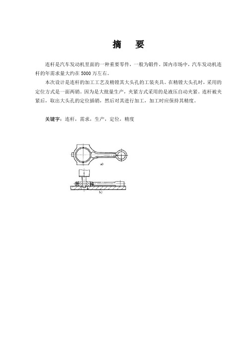
摘要连杆是汽车发动机里面的一种重要零件,一般为锻件。
国内市场中,汽车发动机连杆的年需求量大约在5000万左右。
本次设计是连杆的加工工艺及精镗其大头孔的工装夹具。
在精镗大头孔时,采用的定位方式是一面两销。
因为是大批量生产,夹紧方式采用的是液压自动夹紧。
连杆被夹紧后,取出大头孔的定位插销,然后对其进行加工,加工时应保持其精度。
关键字:连杆,需求,生产,定位,精度ABSTRACTLinkage is an automotive engine inside an important part, generally forgings. Domestic market, the car engine connecting rod in the annual demand of about 50 million or so.The design of the connecting rod processing and precision boring big holes in its fixture. Precision Boring bulk of the hole, the position is a two way marketing. Because of mass production, clamping methods make use of automatic hydraulic clamping. Linkage was clamping, removal of the bulk of positioning bolt hole, then its processing, and processing should maintain its accuracy.Keywords: linkage, demand, production, positioning, accuracy前言制造业特别是机械制造业是国民经济的支柱产业,现代制造业正在改变着人们的生产方式、生活方式、经营管理模式乃至社会的组织结构和文化。
汽车发动机连杆的工艺规程 毕业设计
连杆螺母的自锁,是利用连杆螺栓螺母上所开六个槽,拧紧螺母后,由于螺母的弹性变形保持有100~120N.m的扭矩。由于该扭矩的作用,使螺母的底面受一向上顶的力,螺母产生的弹性变形卡住螺栓,保证螺母在工作时不会松动。
鹤壁职业技术学院毕业(设计)论文
题目:汽车发动机连杆的工艺及程序设计
专业班级:机电一体化 10级(2)班
姓名:李wenlong
学号:1002312043
指导老师:@@@@@@@
2012年10月
汽车发动机连杆加工工艺分析与设计
摘 要
连杆的作用是将活塞承受的力传给曲轴,并使活塞的往复运动转变为曲轴的旋转运动。连杆由连杆体、连杆盖、连杆螺栓和连杆轴瓦等零件组成,连杆体与连杆盖分为连杆小头、杆身和连杆大头。连杆承受的是冲击动载荷,因此要求连杆质量小,强度高。所以在安排工艺过程时,按照“先基准后一般”的加工原则。连杆的主要加工表面为大小头孔和两端面,较重要的加工表面为连杆体和盖的结合面及螺栓孔定位面。连杆机构中两端分别与主动和从动构件铰接以传递运动和力的杆件。
发动机维护的周期是指进行同级维护的间隔期,一般以车辆行驶里程为依据。如解放CA1040的一级维护周期为1500-2000km,二级维护周期为6000-8000km,桑塔纳、奥迪、夏利等轿车及进口汽车一般没有一级维护和二级维护的提法,如桑塔纳轿车只分为7500km维护、15000km维护、30000km维护。每种维护的项目在有关资料中都有详细规定.其中高级维护包含了低级维护的全部项目。
汽油发动机将汽油的能量转化为动能来驱动汽车,最简单的办法是通过在发动机内部燃烧汽油来获得动能。因此,汽车发动机是内燃机----燃烧在发动机内部发生。
汽车连杆的加工工艺及夹具毕业设计

毕业设计(论文)题目汽车连杆加工工艺及夹具设计系别名称专业名称班级学号学生姓名指导教师二O**年六月毕业设计(论文)任务书I、毕业设计(论文)题目:汽车连杆加工工艺及夹具设计II、毕业设计(论文)使用的原始资料(数据)及设计技术要求:1. 制定年产20万汽车连杆加工工艺规程2. 设计铣剖分面夹具及粗加工大头孔夹具I I I、毕业设计(论文)工作内容及完成时间:1. 查阅相关资料,外文资料翻译(6000字符以上),撰写开题报告。
第1周—第2周2.论证工艺方案,进行性能工艺参数分析、设计和计算第3周—第6周4.绘制产品图、毛坯图第7周—第8周5.. 加工工艺规程卡第9周—第10周6.两套夹具设计第11周—第13周7. 两套夹具装配图、零件图绘制第14周—第16周8. 整理毕业论文及答辩准备—第17周Ⅳ、主要参考资料:【2】濮良贵等主编.机械设计. 北京:高等教育出版社,2001【3】陈马宏钧等主编,典型零件机械加工生产实例. 北京:机械工业出版社,2004 【4】王季琨等主编,机械制造工艺学,天津:天津大学出版社2004【5】孙丽嫒主编,机械制造工艺及专用夹具,北京:冶金工业出版社2004 【6】徐灏主编.机械设计手册(第四版).北京:机械工业出版社.1991【7】Shigley J E,Uicher J J.Theory of machines and mechanisms.New York:McGraw-Hill Book Company,1980毕业设计(论文)开题报告题目汽车连杆加工工艺及夹具设计专业名称班级学号学生姓名指导教师填表日期20** 年 3 月10 日一、选题的意义掌握好常规机械加工工艺方法的基础知识,为适应未来需要,深刻领会现代制作技术的精髓,成为具有创新能力的人和在人才市场竞争中取胜的佼佼者,是我们走向工程设计过程中必须要经历的过程。
同时注重分析论述现代制造技术,与现代科技接轨。
连杆盖零件制造工艺分析与夹具设计-铣结合面夹具设计

学院毕业设计课题:连杆盖零件制造工艺分析与夹具设计专题:专业:机械制造及自动化学生姓名:班级:学号:指导教师:完成时间:摘要我设计的是基于连杆盖零件的加工工艺和自设计一些工序的专用夹具设计。
平面及孔系是这个零件的主要加工表面。
通常情况下是这样做的。
平面的加工精度要比孔系的加工精度更加容易掌控制。
由此我们可以得出。
我的设计按先面后孔的顺序。
基准选择以连杆盖的输入轴和输出轴的支承孔作为粗基准。
以底面与两个工艺孔作为精基准。
我在此采用坐标法镗孔对支承孔系作出加工。
组合机床贯穿于设计的整个加工性过程。
我选用的专用夹具,它的结构可以不必自锁,由此我们可以得出生产效率较高,我的设计适合大数量、流水线上的加工。
关键词:连杆盖类零件;工艺;夹具;ABSTRACTMy design is the chemical pipe parts machining process and special fixture design process design based on self. The plane and a series of hole is the main processing surface of the part. As is usually the case to do so. The accuracy of the flat surface to machining accuracy than holes easier control. We can draw. My design on the surface after the first hole sequence. Datum selection to the supporting hole seat angle gear input shaft and the output shaft as a rough benchmark. Main processes arrangements to support holes for positioning and processing the top plane.The bottom surface and the two holes as a precision technology base. I hereby use coordinate boring to make processing of bearing hole. Combination machine tool throughout the machining process design. Special fixture I use, its structure can not be locked, so we can get high production efficiency, I design suitable for processing large quantity, on the assembly line.Keywords: chemical pipe parts; technology; fixture;目录摘要 (II)ABSTRACT...............................I II 第1章机械加工工艺规程设计. (2)1.1 零件的分析 (2)1.1.1 零件的作用 (2)1.1.2 零件的工艺分析 (2)1.2 连杆盖问题和工艺过程措施 (3)1.2.1 孔和平面的加工顺序 (3)1.2.2 孔系加工方案选择 (3)1.3 连杆盖加工定位基准的选择 (3)1.3.1 粗基准的选择 (3)1.3.2 精基准的选择 (3)1.4 连杆盖加工主要工序安排 (4)1.5 机械加工余量数值、工序尺寸及毛坯尺寸的确定 (7)1.6 毛坯种类的选择 (8)1.7 选择加工设备和工艺装备 (8)1.7.1 机床选用 (8)1.7.2 选择刀具 (8)1.7.3 选择量具 (8)1.8 机械加工余量、工序尺寸及毛坯尺寸的确定 (8)1.9确定切削用量及基本工时【机动时间】 (10)1.10 时间给定额度计算及生产安排 (19)第2章铣结合面夹具设计 (21)2.1研究原始质料 (21)2.2定位基准的选择 (21)2.3 切削力及夹紧分析计算 (21)2.4 误差分析与计算 (22)2.5 零、部件的设计与选用 (23)2.5.1定位销选用 (23)2.5.2 定向键与对刀装置设计 (24)2.6 夹具设计及操作的简要说明 (25)总结 (27)参考文献 (28)致谢 (29)第1章机械加工工艺规程设计1.1零件的分析1.1.1零件的作用题目给出的零件是连杆盖。
连杆加工工艺及夹具设计毕业设计
连杆加工工艺及夹具设计毕业设计一、引言随着机械加工的不断发展,数控加工设备的应用越来越广泛,加工工艺和夹具设计也成为机械加工过程中至关重要的一环。
本文就连杆加工工艺及夹具设计进行研究和探讨。
二、材料和加工工艺流程1. 材料选择连杆是一种将发动机汽缸盖、活塞和曲轴连接在一起的元件,因此其材料必须具有高强度、高硬度和高耐磨性。
一般来说,连杆所采用的材料有:铸钢A4840、A319、A356、A357等锻钢25CrMo、40Cr、42CrMo、4340等铝合金2014、2024、2618、4032等不锈钢316、17-4PH等本次设计选择一种常用的锻钢42CrMo,其化学成分和机械性能如下表:2. 加工工艺流程锻造加工是制造连杆的常用工艺,它能够保证材料的均匀性、造型的精度和表面光滑度。
加工流程如下:3. 热处理工艺将锻好的连杆进行调质处理,以提高其硬度和强度,并保证其在使用过程中的可靠性。
热处理工艺如下:4. 精机加工工艺进行车、铣、钻、镗、磨等加工,以保证其精度和表面质量。
加工工艺如下:5. 检测工艺检测加工后的连杆尺寸和表面质量,以保证其满足设计要求。
检测工艺如下:三、夹具设计1. 设计目的针对连杆加工的特点,设计一种适用的夹具,实现其加工过程的自动化、标准化和高效化,提高生产效率和质量。
2. 夹具设计要求稳定性:夹具必须牢固而稳定,以免影响加工精度和安全性。
适用性:夹具必须适用于不同类型的连杆,以实现高度的通用性。
易用性:夹具的操作和维护必须简便、便捷,以提高生产效率和操作员工作舒适度。
3. 夹具设计方案夹具采用定位销和压板两种组合结构,用于夹持连杆内孔和外圆,其结构示意图如下:在加工过程中,通过螺旋压紧装置将夹具紧固在工作台上,然后使用气缸控制压板的升降和紧缩,完成对连杆的夹持。
四、结论本文针对连杆加工工艺及夹具设计进行了研究和探讨,设计了一套适用于锻造加工的加工流程,并提出了一种稳定、适用、易用的夹具设计方案。
毕业答辩 连杆加工工艺及夹具设计

切削用量的选择
• 粗加工是加工精度与表面粗糙度要求不高, 毛坯余量较大。因此,选择粗加工的切削 用量时,要尽可能保证较高的单位时间金 属切削量(金属切除率)和必要的刀具耐 用度,以提高生产效率和降低加工成本。
返回
连杆机械加工工艺过程
连杆的主要加工表面为大、小头孔和两端面,较重要的加工 表面为连杆体和盖的结合面及连杆螺栓孔定位面,次要加工表 面为轴瓦锁扣槽、油孔、大头两侧面及体和盖上的螺栓座面等。
连杆的机械加工路线是围绕着主要表面的加工来安排 的。连杆的加工路线按连杆的分合可分为三个阶段:第一阶段 为连杆体和盖切开之前的加工;第二阶段为连杆体和盖切开之 后的加工;第三阶段为连杆体和盖合装之后的加工。第一阶段 的加工主要是为其后续加工准备精基准(端面、小头孔和大头 外侧面);第二阶段主要是加工除精基准以外的其他表面,包 括大头孔的粗加工,为合装做准备的螺栓孔和结合面的粗加工, 以及轴瓦锁扣槽的加工等;第三阶段则主要是最终保证连杆各 项技术要求的加工,包括连杆合装后大头孔的半精加工和端面 的精加工及大、小头孔的精加工。如果按连杆合装前后来分, 盒装之前的工艺路线属主要表面的粗加工阶段,合装之后的工 艺路线则为主要表面的半精加工,精加工阶段。
• 4)切削力及夹紧力的计算
• 5)定位误差分析 • 对于粗加工的夹具,都应该进行定位误差
和稳定性的计算,以及设计的夹具能否满 足零件的加工和各项尺寸要求。
总结
通过对汽车连杆的机械加工 工艺的分析及对铣结合面夹具的 设计,使我学到了更多有关机械 加工的知识,也在过程中完善了 自己的学习,对平时不明白的地 方又有了一次更深入的学习。能 更好的应用到自己的实际工作中。
连杆盖零件的机械加工工艺规程及夹具设计

设计说明书题目:连杆盖零件的工艺规程及拉,铣15槽的工装夹具设计学生:学号:专业:班级:指导老师:摘要本次设计内容涉及了机械制造工艺及机床夹具设计、金属切削机床、公差配合与测量等多方面的知识。
连杆盖加工工艺规程及其铣15mm槽的夹具设计是包括零件加工的工艺设计、工序设计以及专用夹具的设计三部分。
在工艺设计中要首先对零件进行分析,了解零件的工艺再设计出毛坯的结构,并选择好零件的加工基准,设计出零件的工艺路线;接着对零件各个工步的工序进行尺寸计算,关键是决定出各个工序的工艺装备及切削用量;然后进行专用夹具的设计,选择设计出夹具的各个组成部件,如定位元件、夹紧元件、引导元件、夹具体与机床的连接部件以及其它部件;计算出夹具定位时产生的定位误差,分析夹具结构的合理性与不足之处,并在以后设计中注意改进。
关键词:工艺、工序、切削用量、夹紧、定位、误差。
谢谢朋友对我文章的赏识,充值后就可以下载说明书。
我这里还有一个压缩包,里面有相应的word说明书(附带:机械加工工艺过程及工序卡片)和CAD图纸。
我可以将压缩包免费送给你。
需要其他设计题目直接联系!!ABSTRCTThis design content has involved the machine manufacture craft and the enginebed jig design, the metal-cutting machine tool, the common difference coordination and the survey and so on the various knowledge.The reduction gear box body components technological process and its the processing ¢140 hole jig design is includes the components processing the technological design, the working procedure design as well as the unit clamp design three parts. Must first carry on the analysis in the technological design to the components, understood the components the craft redesigns the semi finished materials the structure, and chooses the good components the processing datum, designs the components the craft route; After that is carrying on the size computation to a components each labor step of working procedure, the key is decides each working procedure the craft equipment and the cutting specifications; Then carries on the unit clamp the design, the choice designs the jig each composition part, like locates the part, clamps the part, guides the part, to clamp concrete and the engine bed connection part as well as other parts; Position error which calculates the jig locates when produces, analyzes the jig structure the rationality and the deficiency, and will design in later pays attention to the improvement.Keywords:The craft, the working procedure, the cutting specifications, clamp, the localization, the error目录序言 (1)一. 零件分析 (2)1.1 零件作用 (2)1.2零件的工艺分析 (3)二. 工艺规程设计 (4)2.1确定毛坯的制造形式 (4)2.2基面的选择传 (5)2.3制定工艺路线 (8)2.4机械加工余量、工序尺寸及毛坯尺寸的确定 (11)2.5确定切削用量及基本工时 (14)三夹具设计 (16)3.1问题的提出 (16)3.2夹具设计 (17)3.3切削力及夹紧力计算 (18)3.4定位误差分析 (19)3.5夹紧误差 (20)3.6夹具设计及操作简要说明 (21)总结 (23)致谢 (24)参考文献 (25)序言机械制造业是制造具有一定形状位置和尺寸的零件和产品,并把它们装备成机械装备的行业。
机械设计毕业论文

毕业论文题目:柴油机“连杆”零件的机械加工工艺规程的编制及工装设计班级:机制1103班姓名:高红岩专业:机械制造与自动化指导教师:孙卓摘要机械制造工业是国民经济最重要的部门之一,是一个国家或地区经济发展的支柱产业,其发展水平标志着该国家或地区的经济实力、科技水平、生活水平和国防实力。
机械制造业的生产能力和发展水平标志着一个国家或地区国民经济现代化的程度,而机械制造业的生产能力主要取决于机械制造装备的先进程度,产品性能和质量的好坏则取决于制造过程中工艺水平的高低。
连杆作为传递力的主要部件广泛应用于各类动力机车上,是各类柴油机或汽油机的重要部件。
连杆在传递力的过程中,承受着很高的周期性冲击力、惯性力和弯曲力。
这就要求连杆应具有高的强度、韧性和疲劳性能。
同时,因其是发动机重要的运动部件,故要求很高的重量精度。
随着汽车行业的发展,连杆的需求量在不断增加,也出现了许多不同的加工制造工艺。
关键词:机械制造、机械制造装备、连杆、加工工艺目录绪论 ............................................................................ (4)一. 零件的结构工艺分析 (4)1.1. 零件的作用及保护措施 (4)1.2. 毛坯材料的选用、制造并绘制毛坯图 (6)1.3. 连杆工艺规程的设计 (9)1.4. 零件的工艺过程分析 (13)1.5. 工艺方案的确定 (15)1.6. 机械加工余量、切削用量、工序尺寸的确定 (16)1.7. 工序工时定额的计算 (19)二. 连杆机械加工技术近期发展 (22)三. 连杆的修复 (24)四. 工装设计 (25)五. 总结 (33)六. 致谢 (34)七. 参考文献 (35)八. 毕业设计任务 (36)绪论机械制造工业是国民经济最重要的部门之一,是一个国家或地区经济发展的支柱产业,其发展水平标志着该国家或地区的经济实力、科技水平、生活水平和国防实力。
连杆盖的机械加工工艺规程毕业设计
连杆盖的机械加工工艺规程毕业设计机械制造工艺课程设计课程名称:设计课题:连杆盖的机械加工工艺规程设计专业:班级:姓名:学号:评分:指导老师:(签字)20**年12月 10 日目录一、序言 (2)二、设计任务书 (3)三、计算生产纲领、确定生产类型 (4)四、零件的分析 (4)五、选择毛坯 (4)六、工艺规程设计6.1定位基准的选择 (5)6.2零件表面加工方法的选择 (5)6.3制定工艺路线 (5)6.4确定机械加工余量及毛坯尺寸 (7)6.5工序设计 (7)七、小结 (9)八、参考文献 (10)一、序言机械制造工艺学课程设计是在我们学完了大学的全部基础课、技术基础课以及大部分专业课之后进行的。
这是我们在进行毕业设计之前对所学各课程的一次深入的综合性的总复习,也是一次理论联系实际的训练,因此,它在我们四年大学生活中占有重要的地位,本次课程设计旨在培养学生设计机械加工工艺规程的工程实践能力,通过这次设计我将使我们获得综合运用过去所学全部课程进行机械制造工艺及结构设计的基本能力,为学生搞好毕业设计、走上工作岗位打下坚实基础。
本次课程设计的目的在于:1.培养学生解决机械加工工艺问题的能力。
通过课程设计,熟练运用机械制造技术基础课程中的基本理论以及在生产实习中学到的实践知识,正确地解决一个零件在加工中的定位、夹紧以及工艺路线安排、工艺尺寸的确定等问题,保证零件的加工质量,初步具备设计一个中等复杂程度零件的工艺规程的能力。
2.提高结构设计能力。
学生通过训练,能根据被加工零件的加工要求,选择高效、省力、经济合理而能保证加工质量的夹具,提高结构设计能力。
3.培养学生熟悉并运用有关手册、规范、图表等技术资料的能力。
4.进一步培养学生识图、制图、运算和编写技术文件等基本技能。
就我个人而言,我希望能通过这次课程设计对自己未来将从事的工作进行一次锻炼。
此次课程设计对给定的零件图分析并进行工艺规程设计,其中考察了定位基准的选择,零件表面加工方法的选择,加工工艺路线的拟订及工序加工余量,工序尺寸,公差等相关知识,历时一个月的设计加深了对所学知识的理解,有助于今后能够熟练地运用于工作中。
毕业设计连杆加工工艺规程及精铣连杆盖结合面夹具设计
摘要本毕业设计课题是制订S195型柴油机发动机连杆零件的机械制造工艺规程及粗铣连杆盖结合面夹具设计,目的是希望能在降低产品的生产本钱的同时又能够制造出品质优良的产品,在最少的工序或加工时刻中制造出知足形状、尺寸、精度、表面粗糙度等要求的产品。
设计应在保证加工精度的同时,又利用工件装卸的合理夹具结构,并有必然有效价值。
由于理论知识与实践体会的有限。
我将考虑采纳普遍性强的加工方式,但该零件的机械加工工艺规程能够适当采纳较为先进的制造工艺方式和专用机床设备,刀具和量具。
本课题的要紧内容是分析零件的技术条件画出零件图及毛坯图。
拟定合理的工艺线路,粗镗大头孔夹具草图及夹具图。
本设计采纳了连杆体与连杆盖分离锻造,并制定相对合理的工艺线路。
在夹具设计部份,以大小头孔端面、大头孔工艺凸台及小头孔为定位基准,符合定位原理并达到定位目的,夹紧机构那么采纳螺旋夹紧机构,亦即达到夹紧成效。
关键词: 连杆;工艺规程;夹具设计;CAD图AbstractThe graduation design topic is formulating S195 diesel engine connecting parts manufacturing procedure and boring head hole fixture design, want to reduce production cost in the also can produce good quality products at least, the process of manufacturing and processing time meet the shape, size, accuracy and surface roughness and requirements of the product. Design should guarantee the machining accuracy of workpiece loading and unloading, and use of reasonable fixture structure, and has certain practical value. Due to the theoretical knowledge and practical experience. I will consider using universal stronger processing method, but the machining procedure can appropriate USES advanced manufacturing technology and special machine equipment, tools and measuring tool. The main content of this project is to analyze the technical conditions of the parts and painted parts blank. The plan was reasonable process route, big hole clamp sketches and boring fixture. This design USES the connecting rod body and connecting separated, and formulate relative reasonable forging process. In part, the size of fixture design with head big hole hole surface, small head for convex and locating datum, and achieve the goal orientation positioning principle, clamping mechanism using spiral clamping institutions, i.e. reached clamping effect.Key words: Connecting rod, Procedure, Fixture design, CAD drawings引言这次设计是咱们在学校的最后一次设计了。
- 1、下载文档前请自行甄别文档内容的完整性,平台不提供额外的编辑、内容补充、找答案等附加服务。
- 2、"仅部分预览"的文档,不可在线预览部分如存在完整性等问题,可反馈申请退款(可完整预览的文档不适用该条件!)。
- 3、如文档侵犯您的权益,请联系客服反馈,我们会尽快为您处理(人工客服工作时间:9:00-18:30)。
摘要本次设计内容涉及了机械制造工艺及机床夹具设计、金属切削机床、公差配合与测量等多方面的知识。
连杆盖制造工艺规程及其铣15mm槽的夹具设计是包括零件加工的工艺设计、工序设计以及专用夹具的设计三部分。
在工艺设计中要首先对零件进行分析,了解零件的工艺再设计出毛坯的结构,并选择好零件的加工基准,设计出零件的工艺路线;接着对零件各个工步的工序进行尺寸计算,关键是决定出各个工序的工艺装备及切削用量;然后进行专用夹具的设计,选择设计出夹具的各个组成部件,如定位元件、夹紧元件、引导元件、夹具体与机床的连接部件以及其它部件;计算出夹具定位时产生的定位误差,分析夹具结构的合理性与不足之处,并在以后设计中注意改进。
关键词:连杆盖;工艺设计;工序设计;专用夹具ABSTRACTThis design involves the machinery manufacturing process and fixture design, metal cutting machine tool, tolerance and measurement and other aspects of knowledge.Fixture design of connecting rod cap manufacturing process planning and milling15mm groove is the design process design, including the parts processing process design and fixture three.In the process of design should first of all parts for analysis, to understand the parts of the process to design blank structure, and choose the good parts machining datum, design a part of the process route; then the parts of each step of the process dimension calculation, is the key to determine the process equipment and cutting the amount of each working procedure design; then the special fixture fixture design, selection of the various components, such as the connecting part positioning element, clamping elements, guiding elements, fixture and machine tools and other components; the positioning errors calculated fixture positioning, analysis the rationality and shortcoming of the fixture structure, pay attention to improve and design in later.Keyword: connecting rod cap; process design; process design; fixture目录摘要 0ABSTRACT (1)目录 (2)第一章零件的分析 (3)1.1零件的作用 (3)1.2 零件的工艺分析 (3)第二章工艺规格的设计 (6)2.1 确定毛坯的制造形式 (6)2.2 基准的选择 (6)2.2.1 粗基准的选择 (6)2.2.2精基准的选择 (6)2.3 制定工艺路线 (7)2.3.1 表面加工方法的确定 (7)2.3.2 确定工艺路线 (7)2.4机械加工余量、工序尺寸及毛坯尺寸的确定 (8)2.5确定切削用量及基本工时 (9)2.5.1 粗铣连杆盖端面和侧面 (9)2.5.2 钻2-M12的孔 (9)2.5.3 攻丝M12 (10)2.5.4镗直径为81mm的孔 (11)2.5.5 钻直径为19的孔 (11)2.5.6 车直径为21宽1.1的沟槽 (13)2.5.7 铣宽15H9槽面 (13)第三章铣床夹具的设计 (15)3.1 设计任务 (15)3.2 夹具方案分析 (15)3.2.1 工件的定位方案分析 (15)3.2.2 夹紧方案分析 (16)3.2.3 夹具体设计 (16)3.2.4 切削力夹紧力计算 (17)3.3.5 定位误差分析 (17)结束语 (19)致谢 (20)参考文献 (21)第一章零件的分析1.1零件的作用连杆盖主要和连杆组合成一体,作为组合机体来使用,是汽车上的动力连接装置中的主要零件。
连杆由连杆体和连杆盖两部分组成。
连杆体及连杆盖上的大头孔用螺栓和螺母与曲轴装在一起,连杆盖是其中一个重要的部分。
此外,为了减少摩擦和便于维修,连杆的大头孔内装有轴瓦,连杆盖还起到固定和定位轴瓦的作用。
1.2 零件的工艺分析此零件为连杆的合件之一——连杆盖,连杆盖的视图完整,尺寸、公差及技术要求齐全。
此零件形状结构较为简单,零件各表面的加工并不困难,但是基准孔Ø81+0.021 0mm以及小头孔要求表面粗糙度Ra1.6µm偏高。
基本思路为先加工大头孔再以其为基准来加工小头孔。
在小头孔中间的大的沟槽需要用R67mm刀具加工,同样在加工大头孔内表面的沟槽时也要用特殊的R25mm的刀具加工。
零件图上的主要技术要求有:1.该连杆盖为整体铸造成型,其外形可不再加工,根据GB/T 6414-1999的规定,铸件尺寸公差代号为CT公差等级分为16级,由于零件的轮廓尺寸不大,形状不是很复杂,为大批量生产,从减少加工难度来说,经查机械制造工艺手册,毛坯采用铸造成型。
2.铸件应消除内应力。
3.不允铸件许有夹渣、气孔、疏松等缺陷。
4.连杆小头孔对A基准的平行度公差为0.01mm。
5.大头孔两端的台阶面对B基准的对称度公差为0.3mm。
6.小头孔中间的沟槽,对基准B的对称度为0.2mm。
7.铸件毛坯需要经过人工时效处理。
8.未注明倒角均为1×45º。
9.去毛刺,锐边倒钝。
10.未注明铸造圆角R2-R5。
11.材料 QT450-10 。
12.连杆大小头孔平行度的检验,可采用穿入专用心轴,在平台上用等高的V 型块支撑连杆大头孔心轴,测量大头孔心轴在最高位置时两端的差值,其差值一半即为平行度误差。
第二章工艺规格的设计2.1 确定毛坯的制造形式在各类机械中,连杆盖为为传动件,由于其在工作时处于运动中,经常受冲击和高压载荷,要求具有一定的强度和韧性。
该零件的材料选择QT450-10,零件的轮廓尺寸不大,形状不是很复杂,为成批量生产模型,从减少加工难度来说,经查机制工艺手册,毛坯采用铸造成型。
因为零件形状并不复杂,但为减小加工时的切削用量和提高生产效率,节约毛坯材料,毛坯形状可以与零件形状接近,即外形做成台阶形。
由于工艺原因,和质量要求,内部孔小于25mm不铸出。
2.2 基准的选择2.2.1 粗基准的选择(1)由连杆盖有孔、沟槽等都需加工,而孔作为精基准应先加工,因此选外圆及一端面为粗基准。
(2)在保证各加工面有加工余量的前提下,使重要孔的加工余量尽量均匀。
(3)要保证定位准确,加紧可靠。
2.2.2精基准的选择该零件是带孔的盘状零件,孔是其设计基准,为避免由于基准不重合而产生误差,应选孔为定位基准,即选Ø81+0.021 0mm孔及一端面为加工精基准。
2.3 制定工艺路线2.3.1 表面加工方法的确定该零件的加工面有内孔、端面、小孔及槽等,材料为QT450-10。
参考有关资料,其加工方法的选择如下:1.毛坯的两端面互为基准加工,表面粗糙度为Ra3.2µm,需粗铣-半精铣。
2.大头孔Ø81+0.021 0mm:内表面粗糙度为Ra1.6µm,需进行粗镗-精镗。
3.小头孔Ø20+0.023 0mm:内表面粗糙度为Ra1.6µm,需进行钻-扩-半精铰。
4.大头孔内沟槽:表面粗糙度为Ra6.3µm,一次成型磨即可。
5.切割面:表面粗糙度为Ra1.6µm,需精铣。
6.两台阶面:底面为Ra6.3µm,侧面为Ra1.6µm,故采用粗铣台阶面后,侧面进行精铣并保证距离尺寸94 0 +0.02mm,以及对称度0.3mm A。
7.两个螺纹孔的加工:钻-铰孔。
8.小头孔的大沟槽采用R67mm的成型铣刀去加工。
9.大头孔内表面的沟槽采用R25的砂轮磨削。
10.小头孔里面的沟槽用精细的镗刀加工。
2.3.2 确定工艺路线连杆的加工工艺路线一般是先进行外形的加工,再进行孔、槽等加工。
其加工包括各侧面和端面的加工,按照先加工基准面及先粗后精的原则进行。
连杆盖加工可按下面工艺路线进行。
工序Ⅰ:铸造毛坯。
工序Ⅱ:人工时效处理。
工序Ⅲ: 铣上下两端面工序Ⅳ:铣下面各端面和侧面工序Ⅴ:镗直径为81mm的孔工序Ⅵ:钻2×M12的螺纹孔工序Ⅶ:钻Ø20的孔工序Ⅷ:车直径为21,宽1.1mm的沟槽工序Ⅸ:铣宽15mm的槽工序Ⅹ:检查各个部分的尺寸和精度。
工序Ⅺ:组装入库。
2.4机械加工余量、工序尺寸及毛坯尺寸的确定1.铸件质量:零件表面无明显的裂纹等缺陷。
2.加工精度:零件除孔以外的各表面为一般加工精度。
3.机械加工余量。
根据铸件质量、形状,以及各个加工部位的要求毛坯尺寸和余量如下:表:毛坯尺寸和余量加工表面基本尺寸mm 毛坯尺寸mm 单边总加工余量mm 小头孔直径Ø 20 0 10大头孔直径Ø 81Ø 70 5.5零件厚度43 46 1.5大头孔两端深度8.5 0 4.25 铸造圆角R3-R5其余余量Z=2.52.5确定切削用量及基本工时 2.5.1 粗铣连杆盖端面和侧面1)选择刀具刀具选取不冲磨损硬质合金套式面铣刀,刀片采用YG8 2)决定铣削用量因为加工余量不大一次加工完成a p =1.5mm d 0=40mm v=125m/min z=4根据X51型铣床说明书,其功率为7.5kw ,中等系统刚度。
根据表查出f z =0.2mm/齿,则转速n=1000v/πd 0=995r/min 按机床标准选取n w =750r/min则切削速度为v=πd n/1000=190.8m/min当n w =750r/minm f =w fzn =0.2*4*750=600mm/r按机床标准选取m f =600mm/r 3)计算工时切削连杆盖端面工时:l=90mm ,l 1=9mm ,l 2=3mm ,则机动工时为 1T =((9+3+90)/750*0.2)*2=1.04min切削连杆盖侧面工时:l=110mm ,l 1=9mm ,l 2=3mm ,则机动工时为 2T =((9+3+(110)/750*0.2)*2=1.63min2.5.2 钻2-M12的孔1)决定机床要素钻M12螺纹底孔Ø10确定进给量f:根据参考文献,当钢的σb<800Mpa,d0=10mm时,f=0.39~0.47m/r由于本零件在加工Ø4.8孔时属于低刚度零件,故进给量应乘以系数0.75则进给量f=0.75*(0.39~0.47)=0.295~0.35m/r根据Z525机床说明书,现取f=0.25mm/r切削速度:根据参考文献,查得切削速度v=18m/min,所以实际转速n=1000*18/π*10=573r/min根据机床说明书,取nw=965r/min,故实际切削速度为v=965*π10/1000=30m/min2)计算工时切削工时:l=10mm,l1=9mm,l2=3mm,则机动工时为3T=(9+3+10/0.3*965)*2=0.14min2.5.3 攻丝M121)决定机床要素攻螺纹M12mmv=15m/mm ns=217r/min按机床选取nw=195r/min,则v=13.4r/mm 2)计算工时机动时 l=20mm,l1=5mm,l2=3mm,2.5.4镗直径为81mm的孔1)选择加工机床和刀具加工要求精镗孔φ81H7机床:T6210坐标镗床刀具:刀具材料为硬质合金、YG8、刀杆尺寸为12mm12mm,长度为500mm。
