钻头夹具三维造型设计
回转式钻模三维设计与仿真
毕业设计(论文)题目(回转式钻模三维设计与仿真)系别:专业名称:学生姓名:学号:指导教师姓名、职称:完成日期年月日目录摘要 (I)Abstract (II)前言 (1)第一章钻孔夹具设计的要求 (2)1.1 钻孔夹具方案设计 (2)1.2 了解夹具总体设计的要求 (2)1.3 机床夹具的发展概括 (3)1.4 机床夹具的发展方向 (4)1.5 钻床夹具的概括 (5)1.5.2钻床夹具的设计要点 (5)第二章钻床夹具设计特点 (7)2.1 确定夹具的类型 (7)2.2 钻模的主要类型 (7)2.3夹具的特点 (9)第三章工件的夹紧计算及其选择 (10)3.1 工件的夹紧 (10)3.1.2 夹紧座 (11)3.1.3 夹紧压板 (11)3.1.4 夹紧螺钉 (12)3.2 夹紧力的选择 (12)3.2.1 夹紧力方向 (12)3.2.2 夹紧力的作用点 (13)3.2.3 夹紧力的计算 (13)第四章夹具结构分析与设计 (16)4.1 夹具的夹紧装置和定位装置 (16)4.2 夹具的导向 (17)4.3 钻孔与工件之间的切屑间隙 (18)4.4 钻模板 (18)4.5 总体分析夹具 (19)总结 (20)参考文献 (21)致谢 (22)摘要在机械制造各行业的工艺过程中广泛应用着各种不同的,用以固定加工对象,使之占有正确位置,以便接受施工的一种工艺装备,统称为夹具。
因此,无论是在机械加工,装配,检验,还是在焊接,热处理等冷,热工艺中,以及运输工作中都大量采用夹具。
但在机械加工中应用最为广泛的是金属切削机床上使用的夹具,我们称其为机床夹具。
它在保证产品优质,高产,低成本,充分发挥现有设备的潜力,以便工人掌握复杂或精密零件加工技术,以减轻繁重的体力劳动等诸方面起着巨大的作用。
因此,机床夹具的设计和使用是促进生产迅速发展的重要工艺措施之一。
为此,在本次毕业设计时,选择了机床夹具设计。
本文主要围绕机床钻孔夹具设计为中心。
法兰盘钻孔夹具三维设计说明书

毕业设计说明书课题名称:车床法兰盘工艺规程与钻孔专用夹具三维设计学生姓名汪校明学号 ************所在学院浙江机电职业技术学院专业机械制造与自动化班级机制1113指导教师方刚强起讫时间:2014 年 3 月25 日~2014 年 5 月16 日课题名称车床法兰盘工艺规程与钻孔专用夹具三维设计摘要我的毕业设计的课题是车床法兰盘工艺规程及专用夹具的三维设计,主要内容如下:首先,对零件进行分析,主要是零件作用的分析和工艺分析,通过零件分析可以了解零件的基本情况,而工艺分析可以知道零件的加工表面和加工要求。
根据零件图提出的加工要求,确定毛坯的制造形式和尺寸的确定。
第二步,进行基面的选择,确定加工过程中的粗基准和精基准。
根据选好的基准,制订工艺路线,通常制订两种以上的工艺路线,通过工艺方案的比较与分析,再选择可以使零件的几何形状、尺寸精度及位置精度等技术要求得到合理的保证的一种工序。
第三步,根据已经选定的工序路线,确定每一步的切削用量及基本工时,并选择合适的机床和刀具。
对于粗加工,还要校核机床功率。
最后,设计第三道工序—钻法兰盘孔的夹具。
先提出设计问题,再进行分析,用pore软件进行设计三维实体,然后把设计的过程整理为说明书。
关键词:机械设计;加工工艺;夹具设计;Pro/E Wildfire目录摘要 (I)第1章绪论 (1)1.1 引言 (1)1.2 主要机械结构分析 (2)1.3 切削力及夹紧力计算 (2)1.4 定位误差分析 (4)1.5 夹具设计及操作的简要说明 (4)第2章结构设计 (5)2.1 设置工作目录 (5)2.1.1新建文件夹 (5)2.1.2设置工作目录 (5)2.2 法兰盘夹具的造型设计 (5)2.2.1新建零件 (5)2.2.2创建底座结构 (5)2.2.3 拉伸造型操作1 (7)2.2.4 拉伸造型操作2 (8)2.2.5 拉伸造型操作3 (9)2.2.5 拉伸造型操作4 (10)2.2.6 拉伸造型操作5 (11)2.2.7 拉伸造型操作6 (13)2.2.8 拉伸造型操作7 (15)3.1建立圆角 (16)3.1.1 建立圆角操作1 (16)3.1.2 建立圆角操作2 (17)4.1创建孔 (18)4.1.1 创建孔操作1 (18)4.1.2 创建孔操作2 (19)4.1.3 创建孔操作3 (20)4.1.4 创建孔操作4 (22)4.1.5 创建孔操作5 (23)4.1.6 创建孔操作6 (24)5.1完成法兰盘钻孔专用夹具的设计与绘图 (25)参考文献 (27)致谢 (28)第1章绪论1.1 引言Pro/E是美国PTC公司于1989年推出的三维CAD/CAM系统,历经多年的发展与推广,已成为当今世界上最流行的高端CAD/CAM软件,其全新的设计理念已成为CAD领域的新标准。
基于SolidWorks的三维夹具设计
机床夹具标准件部分的建模工作 , 以达到缩短产品开发周期的目的 。 关键词: SolidWorks 机床夹具设计 标准件 建模 中图分类号: TP391 . 9 文献标识码: A
改进的人工免疫算法在机床颤振诊断中的应用
杨益洲 游文明 周益军
( 扬州职业大学机械工程学院, 江苏 扬州 225000 ) 摘 要: 针对人工免疫算法对多样性的要求 , 通过提出了在克隆选择算法的基础上增加一种模拟姓氏继承的 有效提高了算法训练时的效率。在 CA6140 型卧式车床的振动数据进行的实验中, 该方法表 算法, 现出色。 关键词: 人工免疫系统 克隆选择算法
( 4 ) 子零件的分解 利用外挂程序进行零件的分解, 可生成数据库中 的全部子零件。 1. 3 机床夹具标准件库的调用 机床夹具标准件库界面如图 4 所示。 单击图标 “二维示意图 ” 可查看该标准件的二维工程图及其控 “三维渲染图”可查看该标准件的三 单击图标 制参数, 维图片。
( 2 ) 建模 进入 SolidWorks 软件, 新 建模型名称为铰链支座 ( JB / T8034 - 1999 ) 。 使 用 旋 转、 螺旋扫描、 拉伸、 倒角等命令 完成整个铰链支座的建模如 图 2 所示。 ( 3 ) 零件的系列化 在铰链支座模型的文件 夹里新建一个 Excel 表, 并与 模型命名一样。 然后将数据 库( 表 1 ) 里的数据粘贴到 Excel 表里, 删除与尺寸控制无 “ID ” 、 “标准件模板 ” 关的 列 、 “极限偏差” 列 列等, 并修改尺寸命名。 在 SolidWorks 里双击零件, 会出现尺寸, 把鼠标放到某一尺寸上会显 “10 ” “D ( 大径 ) ” 示其特性。如图 3 , 将 的尺寸名 保 “D3 @ 草图 1 ” 。 同 样 把 所 有 的 尺 寸 名 为 Solid存为
夹具设计实例-模板
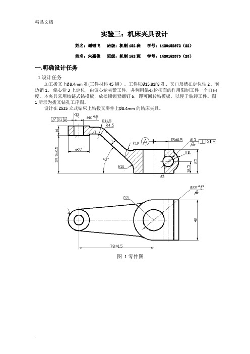
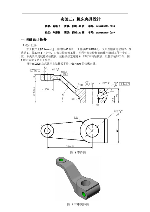
实验三:机床夹具设计姓名:谢银飞班级:机制152班学号:1420152372(22)姓名:朱嘉俊班级:机制152班学号:1420152373(23)一.明确设计任务1.设计任务加工拨叉上8.4mm孔(工件材料45钢)。
工件以15.81F8孔、叉口及槽在定位轴2、削边销1、偏心轮3上定位,由偏心轮夹紧工件,并利用偏心轮楔面的作用限制工件一个自由度。
本夹具采用铰链式钻模板,放松锁锁紧螺钉6,即可回转钻模板,以便于装卸工件。
图1所示为拨叉钻孔工序图。
设计在Z525立式钻床上钻拨叉零件上8.4mm的钻床夹具。
图 1 零件图图 2 三维实体图2.杠杆臂加工工艺分析(1)加工要求加工φ10 和φ13 两孔;孔距为78±0.5;U型槽对称轴线与8.4轴线的水平尺寸为3.1±0.1mm,垂直尺寸为12.5 两孔垂直;8.4对15.81F8轴线平行度公差为0.2;φ13对φ22 轴线垂直度公差为0.1。
Φ10 孔Ra 值为3.2,Φ13 孔Ra 值为12.5。
(2)加工工艺由于该工序中两个孔的位置关系为相互垂直,且不在同一个平面里,要钻完一个孔后翻转90°再钻削另一个孔,因此要设计成翻转式钻夹具。
分析零件图可知,该拔叉的叉角两端面厚度薄于连接的表面,但减少了加工面,使用淬火处理提供局部的接触硬度。
叉角两端面面积相对较大,可防止加工过程中钻头钻偏,保证孔的加工精度,及孔与叉角两端面的垂直度。
其它表面加工精度较低,通过铣削、钻床的粗加工就可达到加工要求;而主要工作表面虽然加工精度相对较高,但也可以在正常的生产条件下,采用较经济的方法保质保量地加工出来,可见该零件工艺性好。
二.定位方案与定位元件1.夹具设计要求已知工件材料为45钢,毛坯为模锻件,所用机床为Z525型立式钻床,大批生产规模。
试为该工序设计一钻床夹具。
2、夹具的设计方案分析:①孔8.4mm为自由尺寸,可一次钻削保证。
该孔在轴线方向的设计基准距离槽mm的对称中心线为 3.1mm±0.1mm;在径向方向的设计基准是孔15.81F8的中心线,其对称度要求为0.2mm,该尺寸精度可以通过钻模保证。
立式钻铣床动力头设计与三维造型

作者简介:宗蒙(1989-),男,博士研究生,主要 从事功能化高分子材料以及材料加工设备设计研究工作。
收稿日期:2020-11-18回转式多工位组合机床,特别适合于加工轮廓尺寸在250 mm 以内的中小零件[1]。
这类机床的应用主要集中于汽车、阀门、气动、液压、制锁、轻工仪表和电气等工业部门[2]。
组成回转式多工位组合机床的主要部件有回转分度装置、中间底座、鼓轮支架、定位装置和动力头等[3]。
这些部件的结构和技术性能,在很大程度上决定了回转式多工位组合机床的结构型式及其技术水平。
回转式多工位组合机床的回转分度驱动一般采用电气机械、液压和气动等方式[4]。
应用液压和电气机械驱动的较多(鼓轮的回转分度一般为液压驱动)而使用气动驱动的较少[5]。
液压由于可采用较高的工作压力,故其结构空间比气动的小。
目前,由于电液比例阀的应用,而大大提高了工作台的分度转位速度,缩短了分度转位时间[6]。
同时,由于电液比例阀可改善机床的起动和缓冲性能,故也可改善工作台定位时的工作条件[7]。
电气机械驱动主要有马氏槽盘和圆柱凸轮间歇运动机构。
据估计目前我国回转式多工位组合机床约占整个组合机床的4%,与机床工业发达的国家相比,无论在数量上还是在技术上均存在一定差距。
本机床为8工位钻铣床,其结构简单、占空间少、操作方便、精度高,是实际生产中非常有用的一种机床。
立式钻铣床动力头设计与三维造型宗蒙(榆林康耐雅新材料技术有限公司, 陕西 榆林 718100)摘要:多工位钻铣床实现了一台机床对一个零件做不同加工的功能,节省了机床,也缩小了占地面积,同时提高了加工精度和生产率,对工人劳动强度也降低很多。
本设计中,钻头的固定采用拉杆式楔形固定,钻头采用套筒及主轴轴面为拉杆的结构,套筒外侧用绝缘胶固定了一个支撑架,钻头的动力由同步齿形带传递到钻头,比起万向轴传递动力要准确且刚性好。
动力采用行星轮的传递方式,保证了各工位的同步工作,节省空间,本机构紧凑,各啮合齿轮之间中心距不超过100 mm ,因而,用齿轮传动可以满足要求,这样可以用标准件对机床快速装配完工,对缩短加工周期有很大好处。
夹具设计及三维建模 毕业设计

夹具设计及三维建模毕业设计夹具设计及三维建模毕业设计一、引言夹具设计及三维建模在工程领域中扮演着至关重要的角色。
夹具是用来夹紧或固定工件,以便对其进行加工、检查或装配的装置。
而三维建模则是将实际物体以三维形式呈现在计算机软件中的过程。
在工程设计领域,这两个领域的重要性不言而喻。
在毕业设计阶段,对于夹具设计及三维建模的研究与应用显得尤为重要。
二、夹具设计的基本原理及步骤1. 夹具设计的基本原理夹具设计的基本原理是确保工件的稳定性和精确性,在加工过程中避免因工件松动或变形导致的加工质量问题。
夹具设计还要考虑到工件的形状、尺寸和加工工艺的特点,确保夹具能够完整地夹住工件,不影响加工表面,同时又方便操作和快速更换。
2. 夹具设计的步骤夹具设计的步骤包括对工件的分析、夹具结构的设计、夹具零部件的布置、夹具的加工工艺设计等。
通过这些步骤,能够设计出满足加工要求的夹具,并在实际生产中发挥作用。
三、三维建模在夹具设计中的应用1. 三维建模在夹具设计中的重要性三维建模为夹具设计提供了直观的模拟环境,通过三维建模软件,可以对夹具的各个部件进行精确的设计和分析。
在三维模型中,可以清晰地看到夹具的结构、工件的位置和夹具与工件的配合情况,从而更好地进行设计和改进。
2. 三维建模软件的选择及应用在实际应用中,常见的三维建模软件包括SolidWorks、Pro/E、UG 等。
这些软件都提供了丰富的建模工具和分析功能,能够满足夹具设计的需求。
通过这些软件,设计人员可以进行夹具的整体设计和零部件的详细设计,同时还可以进行装配仿真和运动分析,确保夹具的稳定性和可靠性。
四、夹具设计及三维建模在毕业设计中的应用在毕业设计阶段,对于夹具设计及三维建模的应用非常重要。
通过选择一个具体的工件,进行夹具设计及三维建模,能够让学生真实地感受到夹具设计及三维建模的实际应用,同时也能够巩固所学的理论知识。
五、总结与展望夹具设计及三维建模是机械工程领域中的重要内容,对于提高产品质量、加快产品开发周期、降低产品开发成本都具有重要意义。
钻床夹具的设计方案
6.2 固定式钻床夹具的设计
1.确定总体结构 套筒工件只有一个需要加工的孔,且在立式钻床上加工,操作比 较简单,因此,确定采用固定式夹具。工件的安装和夹紧可从侧 面完成,可选择最简单的固定钻模结构。夹具中的定位、夹紧和 钻模元件都可以直接安装在夹具体上,无需另外的支撑体。 2.确定定位方案
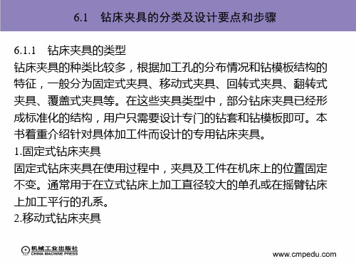
6.1 钻床夹具的分类及设计要点和步骤
(5)加工大、中型工件上同一表面或平行表面上的多个小孔时,可 采用覆盖式结构。 2.钻套的选择和要求 钻套在夹具中不仅决定着孔加工的准确性和精度,还影响着夹具 使用的方便性、可维护性和生产效率。钻套类型的选择(可参见 第2单元 夹具基本元件的设计)和设计要注意以下几点。 (1)固定钻套 结构简单,钻孔精度高,适用于单一钻孔工序和小 批量生产使用。 (2)可换钻套 当钻套发生磨损或孔径有变化时,便于及时更换。 (3)快换钻套 当工件需要钻、扩、铰多工序的加工时,能够迅速 更换不同直径的钻套。
6.1 钻床夹具的分类及设计要点和步骤
6.1.1 钻床夹具的类型 钻床夹具的种类比较多,根据加工孔的分布情况和钻模板结构的 特征,一般分为固定式夹具、移动式夹具、回转式夹具、翻转式 夹具、覆盖式夹具等。在这些夹具类型中,部分钻床夹具已经形 成标准化的结构,用户只需要设计专门的钻套和钻模板即可。本 书着重介绍针对具体加工件而设计的专用钻床夹具。 1.固定式钻床夹具 固定式钻床夹具在使用过程中,夹具及工件在机床上的位置固定 不变。通常用于在立式钻床上加工直径较大的单孔或在摇臂钻床 上加工平行的孔系。 2.移动式钻床夹具
6.1 钻床夹具的分类及设计要点和步骤
(2)铰链式钻模板 钻模板与夹具体(或其他元件)为铰链连接,可 以绕铰链轴翻转,以方便工件的装夹和拆卸。 (3)移动式钻模板 钻模板在保持水平位置不变的情况下,沿垂直 方向上下移动,以方便工件的装夹和拆卸。 (4)可卸式钻模板 钻模板设计成独立的结构体,根据加工的实际 需要可通过夹具上的特殊定位元件随时安装固定,或者单独使用 (如覆盖式钻床夹具)。 4.夹具体的要求 钻床夹具的夹具体结构形式比较复杂多样,应根据加工件的具体 情况选择合适的结构,同时注意以下几点。 (1)夹具体应具有足够的强度和刚性。
钻床专用夹具设计(装配图)--课程设计说明书

洛阳理工学院课程设计说明书课程名称:机械制造装备设计设计课题:钻床专用夹具设计专 业:机械设计制造及其自动化年 月月 日日课程设计内容与要求:内容:内容:为盘类设计一套钻模夹具,便于摇臂钻床的加工。
为盘类设计一套钻模夹具,便于摇臂钻床的加工。
设计要求:设计要求:1.在钻床上加工2-Φ10,10,对对C 面垂直度面垂直度>0.02 >0.022.2.要求绘制要求绘制A0夹具装配图一张、夹具装配图一张、A3A3零件图一张、设计说明书一份。
零件图一张、设计说明书一份。
3.3.夹具设计要求合理,有利提高加工精度,保证加工质量,降低加工夹具设计要求合理,有利提高加工精度,保证加工质量,降低加工成本,提高劳动生产率和减轻工人的劳动强度,便于批量生产。
成本,提高劳动生产率和减轻工人的劳动强度,便于批量生产。
设计(论文)开始日期设计(论文)开始日期 年 月 日 指导老师:指导老师:设计(论文)完成日期设计(论文)完成日期 年 月 日年 月 日课程设计评语院系:机械工程系院系:机械工程系专业:机械设计制造及其自动化专业:机械设计制造及其自动化 课程名称:机械制造装备设计课程名称:机械制造装备设计 设计题目:设计题目: 钻床专用夹具设计钻床专用夹具设计 班级:班级:B140231 B140231 学号:学号:B******** B14023113 姓名:殷彦强姓名:殷彦强 课程设计篇幅:图 纸 2 张说明书 24 页指导教师评语:目录前 言 ................................................................................................................................................ (5)5 一. 专用夹具设计专用夹具设计................................................................................................................... .................................................................................................................. 77 1.1设计前的准备工作设计前的准备工作............................................................................................................. ............................................................................................................ 77 1.1.1. 明确工件的年生产纲领明确工件的年生产纲领..................................................................................... .................................................................................... 77 1.1.2. 分析工件零件图和工序图分析工件零件图和工序图................................................................................. ................................................................................ 77 1.1.3. 确定加工方法确定加工方法..................................................................................................... .................................................................................................... 88 1.2. 总体方案的确定总体方案的确定............................................................................................................ ........................................................................................................... 88 1.2.1. 确定定位方案,设计定位装置确定定位方案,设计定位装置......................................................................... ........................................................................ 88 1.2.2 确定夹紧方案,设计夹紧装置确定夹紧方案,设计夹紧装置........................................................................... .......................................................................... 99 1.2.3 确定导向装置确定导向装置..................................................................................................... .................................................................................................... 1111 1.2.4. 夹具体的设计夹具体的设计................................................................................................... .................................................................................................. 112 1.3.夹具装配图绘制夹具装配图绘制............................................................................................................ ............................................................................................................ 1133 1.3.1. 夹具装配图尺寸、公差的标准夹具装配图尺寸、公差的标准..................................................................... .................................................................... 1133 1.3.2. 夹具的定位、夹紧分析夹具的定位、夹紧分析................................................................................... .................................................................................. 113 1.4. 绘制夹具零件图绘制夹具零件图............................................................................................................. ............................................................................................................ 114 1.4.1.钻模板零件图钻模板零件图 ..................................................................................................... .................................................................................................... 114 1.4.2.辅助支承零件图辅助支承零件图................................................................................................ ................................................................................................ 115 1.4.3.六角螺钉零件图六角螺钉零件图................................................................................................. ................................................................................................ 116 1.4.4.夹具底座零件图夹具底座零件图................................................................................................... .................................................................................................. 117 二.夹具装配图相关要求夹具装配图相关要求................................................................................................................ ............................................................................................................... 119 2.1. 夹具装配图上标注的尺寸夹具装配图上标注的尺寸 ............................................................................................. ............................................................................................ 119 2.2. 夹具的制造误差夹具的制造误差 ............................................................................................................. ............................................................................................................ 119 2.3. 装配图上标注的技术要求装配图上标注的技术要求 ............................................................................................. ............................................................................................ 220 2.4. 确定设计方案确定设计方案................................................................................................................. ................................................................................................................ 220 三.最终的设计结构最终的设计结构........................................................................................................................ ....................................................................................................................... 221 四. 致 谢........................................................................................................................................ ........................................................................................................................................ 222 五.感 想.......................................................................................................................................... .......................................................................................................................................... 223 六参考文献参考文献................................................................................................................................... .. (224)前 言随着科学技术的发展,随着科学技术的发展,各种新材料、各种新材料、各种新材料、新工艺和新技术的不断涌现,新工艺和新技术的不断涌现,新工艺和新技术的不断涌现,机械制造机械制造工艺正向着高质量、工艺正向着高质量、高生产率和低成本方向发展。
夹具设计实例-模板
实验三:机床夹具设计姓名:谢银飞班级:机制152班学号:1420152372(22)姓名:朱嘉俊班级:机制152班学号:1420152373(23)一.明确设计任务1.设计任务加工拨叉上8.4mm孔(工件材料45钢)。
工件以15.81F8孔、叉口及槽在定位轴2、削边销1、偏心轮3上定位,由偏心轮夹紧工件,并利用偏心轮楔面的作用限制工件一个自由度。
本夹具采用铰链式钻模板,放松锁锁紧螺钉6,即可回转钻模板,以便于装卸工件。
图1所示为拨叉钻孔工序图。
设计在Z525立式钻床上钻拨叉零件上8.4mm的钻床夹具。
图 1 零件图图 2 三维实体图2.杠杆臂加工工艺分析(1)加工要求加工φ10 和φ13 两孔;孔距为78±0.5;U型槽对称轴线与8.4轴线的水平尺寸为3.1±0.1mm,垂直尺寸为12.5 两孔垂直;8.4对15.81F8轴线平行度公差为0.2;φ13对φ22 轴线垂直度公差为0.1。
Φ10 孔Ra 值为3.2,Φ13 孔Ra 值为12.5。
(2)加工工艺由于该工序中两个孔的位置关系为相互垂直,且不在同一个平面里,要钻完一个孔后翻转90°再钻削另一个孔,因此要设计成翻转式钻夹具。
分析零件图可知,该拔叉的叉角两端面厚度薄于连接的表面,但减少了加工面,使用淬火处理提供局部的接触硬度。
叉角两端面面积相对较大,可防止加工过程中钻头钻偏,保证孔的加工精度,及孔与叉角两端面的垂直度。
其它表面加工精度较低,通过铣削、钻床的粗加工就可达到加工要求;而主要工作表面虽然加工精度相对较高,但也可以在正常的生产条件下,采用较经济的方法保质保量地加工出来,可见该零件工艺性好。
二.定位方案与定位元件1.夹具设计要求已知工件材料为45钢,毛坯为模锻件,所用机床为Z525型立式钻床,大批生产规模。
试为该工序设计一钻床夹具。
2、夹具的设计方案分析:①孔8.4mm为自由尺寸,可一次钻削保证。
该孔在轴线方向的设计基准距离槽mm的对称中心线为 3.1mm±0.1mm;在径向方向的设计基准是孔15.81F8的中心线,其对称度要求为0.2mm,该尺寸精度可以通过钻模保证。
三 钻孔夹具设计

三钻孔夹具设计为了提高劳动生产率,保证加工质量,降低劳动强度,需要设计专用夹具。
由指导老师的分配工序的钻中18孔的钻床夹具。
3.1 钻床的概述钻床是用途广泛的孔加工机床.其主要加工方法是用钻头在实心材料上钻孔,主要用来加工外形复杂,没有对称回转轴线的孔、一般直径不大,精度不太高的子1,如连杆、盖板、箱体、机架等零件上的单孔和孔系.也可以通过钻孔,扩孔,校孔的工艺手段加工精度要求较高的孔,利用夹具还可加工要求一定相互位置精度的孔系,另外钻床还可进行攻螺纹,锐孔和钩端面等工作,钻床在加工时,工件一般不动,刀具则面作旋转主运动.一面作轴向进给运动.钻床的加工方法及其所需运动如图8T所示。
a)钻孔(b)扩孔(C)钱孔(d)攻螺纹(e)钩埋头孔f锐埋头孔(g)钩端面钻床的主要类型有台式钻床、立式钻床、摇臂钻床、铳钻床和中心孔钻床等。
钻床的主参数一般为最大钻孔直径。
钻床夹具,一般习惯上称为钻模。
它是在钻床上进行孔的钻、扩钱、钩、攻螺纹的机床夹具.使用钻模加工时,是借助于钻套确定刀具的位置和引导刀具的进给方向.被加工孔的尺寸精度主要是由刀具本身的精度来保证。
而孔的坐标位置精度,则由钻套在夹具上的位置精度来确定,并能防止刀具在加工过程中发生倾斜。
因此,在结构上都设置安装钻套的钻模板,有固定式,分度式、盖板式、翻转式和滑柱式等主要类型。
3.2 问题的提出本夹具主要用于钻①18孔,精度要求不高,和其他面没有任何为主度要求,为此,只考虑如何提高生产效率上,精度则不予考虑。
3.3 定位基准的选择基准是用来确定生产对象上几何要素间的几何关系所依据的那些点、线、面。
根据基准的不同功能,基准分为设计基准和工艺基准两大类。
1.设计基准在零件图样上所采用的基准,称为设计基准。
2.工艺基准零件在工艺过程中所采用的基准,称为工艺基准。
工艺基准按用途不同,又分为装配基准、测量基准、工序基准和定位基准。
(1)装配基准装配时用以确定零件在部件或产品中的位置的基准,称为装配基准。
钻M8螺纹孔夹具设计(各行内容)

专项材料
图3.17 移动压板 8
• 主要结构尺寸参数如表3.12所示
L
B
b
l
l1
K
H
h
h1
m
120 30 11 36 50 8 16 4 1.5 12
专项材料
9
• 3.3.7夹具设计及操作的简要说明
• 本套夹具用于加工M8螺纹孔。定位采用常见的一 面两销定位方案。以Φ25孔下表面(一面)及其 内孔(带大端面的长圆柱销),加上宽度为 30mm的下平台(固定定位销)来实现完全定位。 主要考虑工件便于取出夹紧装置采用移动压板夹 紧。工件加工完成后,移动压板向后退一定距离, 工件就可以很方便的取出。工件装夹时,先将工 件放到带大端面的长圆柱销和固定定位销处,然 后将移动压板前移,压在工件上,将螺栓拧紧就 可以进行加工了。加工完成以后将移动压板退出 一定距离,就可以把工件直接取出。如夹具装配 图ZJZ-03所示。
20 18
+0.023 +0.012
0.5
2
专项材料
7
• 3.3.6夹紧装置的设计
• 夹紧装置采用移动的A型压板来夹紧工件, 采用的移动压板的好处就是加工完成后, 可以将压板松开,然后退后一定距离把工 件取出。
• 根据参考文献[11]移动压板(GB2175-80), 其结构如图3.17所示。
• 图3.17 移动压板
• 可见这种定位方案是可行的。
• 3.3.4钻削力与夹紧力的计算
• 由于本道工序主要完成工艺孔的钻、攻螺纹加工,而钻削力远远大于攻 螺纹
专项材料
3
• 切削力。因此切削力应以钻削力为准。由参考文献[9]得:
• 钻削力 钻削力矩 式中:
本套夹具采用移动压板夹紧,
典型夹具的设计
图6-15
分度对定机构的结构形式很多,常用的见图6-16。
钢球对定机构 菱形销(或圆柱销)对定机构 圆锥销对定机构 斜面槽对定机构
图6-16
常见的锁紧机构,除通常的螺杆、螺母外,还有图6-17所示 的几种。偏心轮锁紧机构 楔式源自紧机构 切向锁紧机构 压板锁紧机构
图6-17
第二节 镗床夹具
立轴式、卧轴式、斜轴式
图6-2
(3) 翻转式钻模 翻转式钻床夹具用于加工小型工件同一表面或不同表 面上的孔,结构上比回转式钻模简单,适合于中小批量工 件的加工。
图6-3
(4) 盖板式钻模 特点:钻模板在工件上定位,夹具结构简单轻便,切屑 易于清除。 场合:常用于床身、箱体等大型工件上的小孔加工,也 可用于中小批量生产中的中小工件孔加工。
2.特殊钻套
图6-8
3. 钻套的尺寸与公差
导向孔径d 钻套高度H
钻套与工件距离h
图6-9
铰链式钻模板
可卸式钻模板
图6-10
图6-11
常见的分度装置有两类:回转分度装置、直线移动分度装置
图6-12
图6-13
分度对定机构是保证夹具分度精确的关键元件。 分度对定机构分为轴向分度和径向分度。
图6-14
5.夹具体的设计 1)铣床夹具的夹具体要有足够的刚度和强度,壁厚恰当,
设置适当的筋板。 2)尽可能降低夹具的重心,夹具体高度与宽度之比一般为
H/B<=1~1.5,见图6-35。 3)要有足够的排屑空间,切屑和切削液能顺利排出,必要
时可设计排削槽、排削面。 4)夹具上应设置耳座。 5)重型铣床夹具的夹具体两段还应设置吊装孔或吊环。
图6-4
(5) 滑柱式钻模
滑柱式钻模是一种通用 可调夹具,其结构特点是钻 模板装在可升降的滑柱上的 钻模,其定位元件、夹紧元 件和钻套等可根据工件不同 进行更换,而其他部分可保 持不变。
长方形板钻孔夹具UG建模过程设计
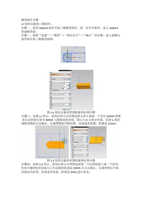
模型制作步骤1.l钩形压板的三维制作:步骤一:使用UG10.0软件开始三维模型制作,第一步打开软件,进入UG10.0的建模界面;步骤二:按照“新建”•“模型”•“修改名字”•“确认”的步骤,进入建模内部界面开始三维模型画图。
图1-1钩形压板的草图轮廓和拉伸步骤步骤三:如图1.l所示,使用拉伸点击草图选择X和Y面画一个直径15mm的圆形以及两条长度为30mm与圆相切的直线,圆心与0点重合约束,在画1条封图1-2钩形压板的草图轮廓和拉伸步骤步骤四:如图1-2所示,使用拉伸点击草图选择第一个拉伸的面上画一个矩形,约束关键的矩形边线与已有边线的距离是IOmm后点击确认,完成草图后开始沿面法向拉伸,结束选项是值,距离是3mm,进行求差;图1-3钩形压板的草图轮廓和拉伸步骤步骤五:如图1・3所示,使用拉伸点击草图选择第一个拉伸的面上画一个直径为7mm的圆形,约束圆心与已有边线圆心重合后点击确认,完成草图后开始沿面法向拉伸,结束选项是值,距离是3mm,进行求差;图1-4钩形压板的倒斜角步骤六:如图1・4所示,用倒斜角命令选中边线开始倒角,距离是7mm;图1-5钩形压板的草图轮廓和拉伸步骤步骤七:如图1-5所示,使用拉伸点击草图选择第一个拉伸的面上用直线画一个三角形,约束好尺寸镜像后点击确认,完成草图后开始沿面法向拉伸,结束选项是值,距离是贯通,进行求差;1.2钩形压板座的三维制作:步骤一:使用UG10.0软件开始三维模型制作,第一步打开软件,进入UG10.0的建模界面;步骤二:按照“新建”-“模型”•“修改名字”•“确认”的步骤,进入建模内部界面开始三维模型画图。
图2-1钩形压板座的草图轮廓和拉伸步骤步骤三:如图2-1所示,使用拉伸点击草图选择X和Y面上画一个直径为30的圆形,约束好圆心与0点重合后点击确认,完成草图后开始拉伸,结束选项是值,距离是5mm;•Ha:A图2-2钩形压板的草图轮廓和拉伸步骤步骤四:如图2-2所示,使用拉伸点击草图选择第一个拉伸的面上用直线画一个直径为25mm的圆形后点击确认,完成草图后开始沿面法向拉伸,结束选项是值,距离是18mm,进行求和;图2-3钩形压板的草图轮廓和拉伸步骤步骤五:如图2-3所示,使用拉伸点击草图选择第一个拉伸的面上投影边线后偏置Imm后点击确认,完成草图后开始沿面法向拉伸,结束选项是值,距离是2mm,进行求差;图2-4钩形压板的草图轮廓和拉伸步骤步骤六:如图2-4所示,使用拉伸点击草图选择第二个拉伸的面上用直线画一个直径为22mm的圆形后点击确认,完成草图后开始沿面法向拉伸,结束选项是值,距离是5mm,进行求和;图2-5钩形压板的草图轮廓和拉伸步骤步骤七:如图2-5所示,使用拉伸点击草图选择第二个拉伸的面上第一个拉伸的面上投影边线后偏置Imm剪裁点多余线条后点击确认,完成草图后开始沿面法向拉伸,结束选项是值,距离是Iomm,进行求和;V图2-6钩形压板的倒斜角步骤八:如图2-6所示,用倒斜角命令选中拉伸后边线开始倒角,距离是Imm;图2-7钩形压板的草图轮廓和拉伸步骤步骤九:如图2-7所示,使用拉伸点击草图选择第二个拉伸的面上画一个直径为16mm的圆形后点击确认,完成草图后开始沿面法向拉伸,结束选项是值,距离是6mm,进行求和;图2-8钩形压板的螺纹孔步骤十:如图2-8所示,用螺纹孔命令选中边线圆心后打M6,深度为15的孔;图2-9钩形压板的草图轮廓和拉伸步骤步骤十一:如图2-9所示,使用拉伸点击草图选择第1个拉伸的面上画一个直径为4mm的圆形后点击确认,完成草图后开始沿面法向拉伸,结束选项是值,距离是贯通,进行求差;1.3夹具体的三维制作:步骤一:使用UG10.0软件开始三维模型制作,第一步打开软件,进入UG10.0的建模界面;步骤二:按照“新建”-“模型”-“修改名字”•“确认”的步骤,进入建模内部图3-1夹具体的草图轮廓和拉伸步骤步骤三:如图3-1所示,使用拉伸点击草图选择X和Y面上画一个250X25Omm 的正方形,约束好正方形中心与0点重合后点击确认,完成草图后开始拉伸,结束距离选项是30mm;图3-2夹具体的草图轮廓和拉伸步骤步骤四:如图3-2所示,使用拉伸点击草图选择正方形的上表面上画一个60X20mm的矩形,约束好位置后点击确认,完成草图后开始拉伸,结束距离选项是100mm,进行求和;图3-3夹具体的草图轮廓和拉伸步骤步骤五:如图3-3所示,使用拉伸点击草图选择正方形的面画一个直径15mm的圆形以及两条长度为20mm与圆相切的直线,圆心到边的距离是分别是20和40mm,在画1条封闭的直线后进行镜像,点击确认,完成草图后开始拉伸,结束选项是值,距离是IoOmm,进行求差;图3・4夹具体的草图轮廓和拉伸步骤步骤六:如图3-4所示,使用拉伸点击草图选择正方形的面画一个直径26mm 的圆形以及两条与圆相切的直线,圆心与步骤五的边线圆心重合,在画1条封闭的直线后进行镜像,点击确认,完成草图后开始拉伸,结束选项是值,距离是5mm,进行求差;图3-5夹具体的倒斜角步骤七:如图3-5所示,用倒斜角命令选中拉伸后边线开始倒角,距离是10mm;图3-6夹具体的螺纹孔1步骤八:如图3-6所示,用螺纹孔命令后打M4,深度为6的孔;图3-7夹具体的螺纹孔2步骤九:如图3・7所示,用螺纹孔命令后打M6,深度为9的孔;图3-8夹具体的螺纹孔3步骤十:如图3-8所示,用螺纹孔命令后打M8,深度为12的孔;1.4可换钻套的三维制作:步骤一:使用UG10.0软件开始三维模型制作,第一步打开软件,进入UG10.0的建模界面;步骤二:按照“新建”-“模型”-“修改名字”-“确认”的步骤,进入建模内部界面开始三维模型画图。
三维造型设计钻床夹具
课程设计任务书三维造型设计设计任务书一、设计题目:钻床夹具二、设计依据1、零件图2、年产量:10000件/年三、设计任务1、三个主要的零件图各1张,共三张2、装配图1张2、课程设计说明书 1份四、设计起讫日期: 2014年6月16日——2014年6月28日零件图图1夹具底座图2 压紧底座图3 支撑架本次课程设计主要是对所学的课程SolidWorks进行一次知识与理论的再一次升华,课程的题目为钻床夹具设计,分析和综合所学的知识定出了建模的思路。
只要的内容讲解了钻床夹具的零件的建模过,在在展现零件建模生成的时候,进一步巩固了SolidWorks所学的零件建模的过程,在生成零件的时候主要运用拉伸、切除命令。
在一个零件生成之后进行装配体的生成,按照老师的要求最终生成零件及装配体的二维工程图。
【关键词】SolidWorks;钻床夹具;零件建模;装配体The curriculum design is mainly on the course SolidWorks a knowledge and theory sublimation course again, titled drilling fixture design, analysis and synthesis of knowledge from the modeling idea. As long as the content on the modeling of drilling fixture parts, in the show parts modeling, to further consolidate the process of parts modeling SolidWorks learned, when generating parts of the main use of stretching, resection of command. The generation of the assembly after a generation of parts, 2D engineering drawing according to the requirements of the teacher finally generate the parts and assembly.【Keywords】SolidWorks; drilling fixture; assembly modeling;第一章前言 (1)第2章钻床夹具总体分析 (3)第3章零件的建模 (5)3.1底座的建模 (5)3.1.1总体思路的设计 (5)3.1.2创建底板 (5)3.1.3拉伸壳体 (6)3.1.4 拉伸上盖面 (7)3.1.5 拉伸凸台并攻丝 (7)3.1.6 加工圆孔凸台孔及圆角 (9)3.2 螺纹杆的建模 (10)3.3 夹具支撑架建模 (11)3.4 压紧板的建模 (18)3.5 压紧座的建模 (21)3.6 卡紧装置 (24)3.7 其它零件的建模 (25)第4章装配体的生成 (26)4.1新建装配体 (26)4.2插入零件 (26)4.3 添加装配关系 (26)参考文献 (27)致谢 (28)第一章前言本次课程设计是本学期SolidWorks这们课程的学习结果的一次检验,我的课程设计的题目是钻床夹具。
钻床夹具工程图设计

下一页 返回
任务2 钻模装配工程图注释设计
• (2)装配尺寸 • 装配尺寸是用于保证产品或部件的工作精度和性能的尺寸。它包括所
有有配合要求的尺寸、零件之间的连接定位尺寸、轴线到轴线的距离 、轴线到基面的距离和基面到基面的距离等。 • (3)安装尺寸 • 将部件安装到其他零部件或基础上所需要的尺寸。如地脚螺栓孔的定 位、定形尺寸等属于安装尺寸。 • (4)外形尺寸 • 机器或部件的总长、总宽和总高尺寸,它反映了机器或部件的体积大 小,以提供该机器或部件在包装、运输和安装过程中所占空间的大小.
上一页 下一页 返回
任务1 钻模装配工程图视图设计
• 针对主视图还没有表达清楚的装配关系和零件间的相对位置,应选用 其他视图及相关的表达方法,如剖视图(包括拆卸画法、沿零件结合 面剖切)和断面等表达方法来表达清楚。装配图中的每一个视图,都 应有其表达的侧重内容。整个表达方案应力求简练、清晰、正确。
任务1 钻模装配工程图视图设计
• (4)其他视图生成(图Ⅺ−8) • 用相同的方法生成左视图,请读者自行操作。 • (5)剖视图创建与剖面线的修改(图Ⅺ−9、图Ⅺ−10) • 根据图纸设计需求,按照后面的剖面线修改方法及步骤,请读者自行
修改练习。 • (6)视图整理(图Ⅺ−11、图Ⅺ−12)
上一页
上一页 下一页 返回
任务2 钻模装配工程图注释设计
• (3)创建球标(图Ⅺ−21) • 4. 技术要求设计 • 技术要求设计如图Ⅺ−22 所示。 • 完成的装配工程图如图Ⅺ−23 所示。
上一页
返回
图Ⅺ−1 钻模装配工程图
返回
图Ⅺ−2 设置工作目录
返回
图Ⅺ−3 工程图配置设置
返回
图Ⅺ−4 建立工程图文件
- 1、下载文档前请自行甄别文档内容的完整性,平台不提供额外的编辑、内容补充、找答案等附加服务。
- 2、"仅部分预览"的文档,不可在线预览部分如存在完整性等问题,可反馈申请退款(可完整预览的文档不适用该条件!)。
- 3、如文档侵犯您的权益,请联系客服反馈,我们会尽快为您处理(人工客服工作时间:9:00-18:30)。
三维造型设计课程设计说明书学院:专业:姓名:学号:课程设计任务书枣庄学院三维造型设计设计任务书一、设计题目:钻头夹具二、设计依据1、零件图2、年产量:10000件/年三、设计任务1、三个主要的零件图各1张,共三张2、装配图1张2、课程设计说明书 1份四、设计起讫日期: 2014年6月16日——2014年6月28日班级:学生:学号:指导教师:零件图摘要solidworks实体设计软件( 最新版本为solidworks2010) 是达索系统(Dassault Systemes S.A)下的子公司开发的一种三维设计软件。
与传统参数化造型CAD 系统如AUTOCAD、Pro/E、UG、CAXA 相比,它有许多优点,主要功能和特点如下:1.强大的建模能力: SolidWorks的特征树可以为使用过SolidWorks的工程师提供熟悉的设计环境;2.高效的装配能力:SWIFT为SolidWorks提供了一系列强大的工具,用来管理特征顺序、配合、草图关系以及尺寸标注和公差规则,使用户可以专注于设计,而不必受CAD系统规则的困扰;3.精确的仿真及有限元分析:SolidWorks提供了CoSMoSMotion与CoSMoSworks两个模块,可以满足用户的动力学及有限元分析;4.软件的高度集成: 可以在轻松完成三维零件建模、装配、钣金成形及三维造型关联的工程图纸、高级智能渲染。
采用拖放式的实体造型并结合智能捕捉与三维定位技术, 我们可以将设计效率与速度大大提高。
正是基于SOLIDWORKS的以上特点, 我们选择了它作为辅助教学的工具软件。
ABSTRACTThe SolidWorks entity design software (the latest version of solidworks2010(Dassault) is the Systemes S.A) in a three-dimensional design software subsidiary development under the. With the traditional parametric CAD system as compared with AUTOCAD, Pro/E, UG, CAXA, it has many advantages, the mainfunction and characteristics are as follows:1 powerful modeling ability of SolidWorks: feature tree can provide design environment familiar to use SolidWorks engineer;The assembly capacity of 2 efficient: SWIFT provides a series of powerful tools for SolidWorks, to manage the characteristic sequence, with the sketch relations,as well as the dimensioning and tolerancing rules, users can focus on design,without CAD rules of system trouble;3 accurate simulation and finite element analysis: SolidWorks providesCoSMoSMotion and CoSMoSworks two module, can satisfy users' dynamics and finite element analysis;Highly integrated 4 software: can easily complete the three-dimensional modeling of parts, assembly, sheet metal forming and 3D modeling related engineering drawings, senior smart rendering. The solid modeling drag and drop and combining with the intelligent capture and 3D positioning technology, we cangreatly improve the design efficiency and speed. It is based on the above SOLIDWORKS characteristics, we choose it as the auxiliary teaching software.目录1、分析过程 (3)1.1、建模设计 (3)1.2、虚拟装配 (4)1.3、效果渲染图 (6)1.4、工程图 (6)1.5、运动分析 (7)2、具体零件绘制步骤 (9)零件1 (9)零件2 (10)零件3 (11)零件4 (12)零件5 (15)零件6 (17)3、装配 (20)4、参考文献 (29)5、致谢 (30)1.分析过程1.1建模设计Solidworks提供功能强大的基于特征的实体建模功能,通过拉伸、旋转、薄壁有:阀体、上盖、心轴、轴承衬套、偏心凸轮、轴承、平键、螺钉、管接头一、调特征、扫描、抽壳、圆角、特征阵列以及打孔等操作来实现产品的设计。
气压阀压螺帽、钢珠、弹簧座、调压弹簧、O型环一、外盖、活塞杆、O型环二、弹簧塞杆、弹簧、调压螺帽、螺塞、管接头二,共有22个零件,以下是主要零件造型的过程。
对于钻头夹具的具体建模设计过程如下:(1)打开Solidworks2010,新建零件1阀体,在基准面中新建草图,依次给予拉伸、旋转除料、倒角、阵列、创建螺纹线、创建基准面及草图,扫描切除、圆角等特征,具体建模尺寸参照建模/机构/结构综合实训教程书,三维建模过程依次如图1所示。
图1(2)新建零件2心轴,在基准面中创建草图后给予旋转增料特征,再创建草图、后给予旋转除料及倒角特征,最后创建草图后拉伸除料,三维建模过程如图2所示。
图2 心轴的建模SolidWorks 提供了生成完整的、车间认可的详细工程图的工具。
工程图是全相关的,当你修改图纸时,三维模型、各个视图、装配体都会自动更新。
从三维模型中自动产生工程图,包括视图、尺寸和标注。
增强了的详图操作和剖视图,包括生成剖中剖视图、部件的图层支持、熟悉的二维草图功能、以及详图中的属性管理员。
使用RapidDraft技术,可以将工程图与三维零件和装配体脱离,进行单独操作,以加快工程图的操作,但保持与三维零件和装配体的全相关。
用交替位置显示视图能够方便地显示零部件的不同的位置,以便了解运动的顺序。
交替位置显示视图是专门为具有运动关系的装配体而设计的独特的工程图功能。
SolidWorks 才提供了一整套完整的动态界面和鼠标拖动控制。
“全动感的”的用户界面减少设计步骤,减少了多余的对话框,从而避免了界面的零乱。
(3)新建零件3上盖,在基准面中创建草图后给予旋转增料特征,后添加倒角特征并给予拉伸除料特征后圆周阵列;同理构建零件4轴承衬套及零件5偏心凸轮模型如图3所示。
图3 上盖、轴承衬套、偏心凸轮的建模(4)从设计库中,取出标准零件,后另存为零件6轴承、7螺钉、8平键,三维模型如图4所示。
图4 轴承、螺钉、平键的建模(5)新建零件9管接头、10调压螺帽、11钢珠,三维模型如图5所示。
图5 垫片、弹簧盖、活塞杆的建模(6)新建零件12弹簧座、13弹簧,14外盖,螺栓及螺帽中螺纹也可使用装饰螺纹线替代,三维模型如图6所示。
图6 弹簧座、弹簧、外盖的建模1.2虚拟装配利用虚拟装配,可以验证装配设计和操作的正确与否,以便及早地发现装配中的问题,对模型进行修改,并通过可视化显示装配过程。
虚拟装配系统允许设计人员考虑可行的装配序列,自动生成装配规划,它包括数值计算、装配工艺规划、工作面布局、装配操作所模拟等。
(1)新建装配体1气压调压阀,插入零件1-22,六角螺母插入4次,并添加配合重合以及同轴心关系,整个装配体如图7所示。
图7 气压阀的装配(2)单击工具中的干涉检查并计算,显示有多处干涉,详细检查干涉皆为螺纹干涉,故可忽略(建议使用装饰螺纹线替代螺纹造型就不存在干涉问题,同时还可提高运行速度),说明装配完全正确,干涉检查如图8所示。
图8 气压阀的干涉检查(3)完成干涉检查无误后,单击插入爆炸视图,爆炸的顺序即为装配的逆顺序,装配体的爆炸效果图如图9所示。
图9 气压阀的爆炸视图1.3效果图渲染效果图是利用插件PHOTOWORKS完成,添加零件的材质为默认塑料、布景为带完整光源的工作间,其余参数默认,渲染效果图如图10所示。
图10 气压阀的渲染效果图1.4工程图新建工程图,新建模板设为A4图纸,插入所需的零件心轴,添加视图、剖视图、断面图、并标注尺寸公差、形位公差、表面粗糙度,生成心轴工程图,如图11所示。
图11 心轴工程图的输出1.5运动分析MOTION是其运动仿真CAE插件,它可建立三维动力学仿真机构模型并添加运动、约束、力、碰撞等,对机构进行仿真模拟、干涉分析、跟踪零件的运动轨迹,分析机构中零件的速度、加速度、作用力、反作用力和力矩等,并可输出动画、图形、表格等多种形式的结果,其分析的结果可指导修改零件的结构设计或调整零件的材料。
其具体的运动过程:气压阀动力由心轴传入,带动凸轮,使活塞杆向左推动,造成左方密封空间变小。
这样让气体的压力增加,管接头内部的弹簧也会因为内部压力的增大而将高压气体排出,从而达到气压阀送出的压力。
当凸轮顶端位于相反方向时,活塞杆就会压缩弹簧的推力而向右运动,让左方密封空间增大,气体通过下方的管接头而进入。
点击工具选项,在菜单中勾选的MOTION选项,后具体操作步骤如下:(1)为了方便在稍后的凸轮机械配合的操作,打开零件凸轮,点击分割线工具,选择基准面做草图将凸轮与活塞杆的接触面分割出4个接触面,具体分割的前后如图12所示。
图12 凸轮面的分割(2)同理凸轮面的配合,打开零件活塞杆,选择基准面做草图并添加拉伸特征,注意不勾选合并实体选项,将会产生两个实体,右击刚生成的长方形实体将其隐藏,如图13所示。
图13 创建活塞杆端部接触平面(3)打开装配体,系统会出现重新构建的对话框,点击确定,将弹簧零件删除,重新创建基准面,并构建弹簧,并添加关系,后保存弹簧,让弹簧具备了关联性,如图14所示。