ts613DNV船级社入级规范2006版
美国船级社船板规范(ABS)2006
美国船级社船板规范(ABS:2006)第二部分第一章造船用材料第一节通则1试验和检查1.1一般要求用于造船及容器设备入级的材料的检验和试验,必须经过验船师的认可并符合以下相关要求。
材料、试验试样、机械性能试验程序如和本节的要求不同,可以通过申请获得批准,对材料生产国的生产工艺应定期认可,包括材料的用途,例如材料用于哪一部分,容器的类型、用途、容器的制造特性等。
1.2制造商认可(2003)(略)1.7对以前认可材料的拒收如果在使用中证明材料不能满足要求,尽管有以前经过检查合格证明,它将被拒收。
1.9试验机校核(2005)试验机应保持良好而准确的状态,达到验船师满意,并对试验机进行校对检查。
所有试验应由合格的人员按认可的国家或国际标准进行。
3缺陷所有材料不得有裂纹,有害的表面裂缝,有害的分层及类似缺陷。
除指明的特殊材料外,除非验船师批准,不得将焊接或修磨用于修补缺陷。
在批准对材料如此处理的情况下,验船师可规定进一步的探测及必需的热处理,然后如果认为满意,经处理的部分应打印上验船师的识别标记并用漆画一个圆圈。
5材料识别制造商应采用一种钢锭、板坯、成品板、型材、铸件的识别系统,以使材料可以追溯到原始炉次,并应给验船师提供便利以对材料进行这种追踪。
7生产厂的证书7.1证书格式除非另有要求,应将所有被接受材料的四份已经过证明的钢厂试验报告及装船资料(可以是分开的或组合的单据)提供给验船师,上面标明材料的级别、炉次识别号、试验结果及装船重量。
其中一份钢厂试验报告由验船师备签后提交给买方,三份由船级社保存使用。
在将经证明的钢厂试验报告及装船资料发送给当地船级社办事处之前,生产厂应向验船师提交一份证书,说明材料已按照批准的工艺生产并且材料满意的经受住了规定的试验,如果在每份经证明的钢厂试验报告上打印上厂名并由授权的生产厂代表签字,则下面的证书格式可以被接受:“我们特此证明,这里所述材料已根据相应规范按工艺生产并根据美国船级社规范的要求进行了试验并取得了满意的结果。
dnv规范
dnv规范
DNV规范是挪威船级社(DNV)针对船舶和海洋工程领域制定的一系列规范和标准。
这些规范覆盖了从设计、建造、操作到维护等各个方面的要求,旨在确保船舶和海洋设施的安全、可靠和高效运行。
DNV规范主要包括以下几个方面的内容:
1. 船舶设计规范:这部分规范主要包括船舶结构设计、船舶稳性计算、船舶操纵性等内容。
其中船舶结构设计规范主要要求船体结构必须具备足够的强度,以承受海上恶劣环境条件下的荷载。
船舶稳性计算规范则要求船舶必须保持良好的稳定性,确保船体不会轻易倾覆。
2. 船舶建造规范:这部分规范主要涉及船舶的建造工艺和施工技术。
其中包括对材料的选择和使用要求,对焊接和防腐处理等工艺的要求,以及对船舶建造过程中的质量控制要求等。
3. 船舶操作规范:这部分规范主要包括船舶的操作指导和安全管理要求。
其中船舶操作指导要求船员必须熟悉船舶操纵性和操作流程,确保船舶能够安全、高效地进行航行。
安全管理要求则涉及船舶应急救援、消防安全、船舶保险和事故调查等方面。
4. 海洋工程规范:这部分规范主要涉及海洋工程设施的设计和建造要求。
其中包括海洋平台的结构设计规范,海底管道的设计和布置规范,海洋风电设备的设计和安装规范等。
总之,DNV规范是船舶和海洋工程领域的重要标准,它不仅
涵盖了船舶和海洋工程设施的设计、建造、操作等方面的要求,更重要的是,它为保障船舶和海洋设施的安全和可靠运行提供了一系列具体的指导和标准。
同时,DNV规范的持续更新和
改进也为船舶和海洋工程行业的发展提供了重要支持。
意大利船级社规范(RINA)2006
意大利船级社船板规范(RINA :2006)意大利船级社船板规范(RINA :2006)PART D第一章第二节材料试验程序1通则1.1 适用范围1.1.1本章节详细说明了材料机械和工艺试验对试验程序、试验设备和试样的要求。
有关焊接的试验程序和试验样第五章有详细说明。
1.2 试验机1.2.1试验机应保持在令人满意和精密的状态中,且每隔一年左右校验一次。
特别的:试验机的精度应在±1%之内。
冲击试验机的冲击能量不小于150J。
2 拉力试验2.1拉力试样2.1.1比例扁平试样对于板带材产品,通常使用比例试样,参数见图1。
t:材料的厚度b:25mm(宽度)L0:5.65S01/2这里S0是横截面。
计量长度可圆整至最近的5mm,与L0的差应小于10%L。
L C:L0+2 S01/2R:25mm(过渡半径)这种产品的拉伸试验样应保留产品的原始轧制面。
当现成可用的试验机能力不足以用于全厚度试样时,则可在一轧制面进行机加工,使试件厚度减薄。
2.1.2非比例扁平试样对上面所提到的情况,也可以使用非比例试样,这种试样标距的长度为200mm,其它参数见图2。
t:材料的厚度b:25mm2.1.3圆试样象2.1.2中提到的对于轧制产品包括棒材拉伸试验样应保留产品的原始轧制面,但是,通常情况下,当厚度大于或等于40mm时,对于a=t的全厚度试样,当试验机能力不足时,也可以使用圆试样,说明见图3。
备注1:对于球墨铸铁和最小延伸率低于10%的材料,R≥1.5d备注2:L c=L0+d/22.1.4圆试样直径比例圆拉伸试样的直径通常为10或14mm。
然而,当不能切取正常试样尺寸时,直径可以为8或6mm。
2.1.5圆试样部位在轧制产品(板材)厚度大于或等于40mm情况下,圆试样的轴心位于距轧制表面1/4厚度部位。
2.2试验程序2.2.1通则由于不同钢种的需要,规定了以下试验参数:a)R eH:屈服应力(屈服点),N/mm2b)R p0.2- R p1.0:验证应力(屈服强度),N/mm2c)R m:抗拉强度,N/mm2d)A:伸长率,%e)Z:断面收缩率,%2.2.2屈服和验证应力的测定在环境温度下进行的拉伸试验,对于有明显屈服现象的材料,屈服强度R eH就是显示盘上指针第一次停止并下落时,在试验设备上显示的载荷。
DNV_2.7.1_2006--集装箱

DNV近海集装箱标准2.7-104/20061.总则1.1范围此认证标准适用于涉及设计,制造,试验,认证,标识和定期检验的用于运输的近海集装箱的相关要求。
此标准覆盖了集装箱的结构和用于操作,装卸,制冷,加热和安全目的的永久设备。
其目的是为了使近海集装箱必须满足如下要求:使用安全,与如下有关:生命环境对船舶和海上设施的潜在危险通过如下选择使其能够重复使用:材料防护便于维修和保养此标准的要求基于近海集装箱的一系列有关操作和使用的假设:他们是被起重机吊钩从其顶部吊装设置单独起吊他们不用排架起吊或使用ISO角件他们能被任何具备充分能力和速度的起重机在世界上任何地方起吊对于限制使用区域(温度气候)的集装箱的认可看附录3他们只有被设计成可堆码时才可以被堆码他们只可以被堆在近海和岸上设施上而不能在运输过程中被堆在船舶上货物或松散设备应被固定在箱子上集装箱必须被设计成能够对其装载的货物和设备提供充分的保护他们按照IMO’S‘支持船安全操作守则’操作按当地法规操作船级社可以批准能够找到的,在总体安全性方面相当于本标准的替代标准。
如果有充分的信息表明已选择的替代标准不满意时这种批准可以取消。
当本标准所用的词‘集装箱’时,其指‘近海集装箱’。
本标准的指引部分和注解部分不作为DNV的要求,只作为设计者和操作者的实用建议和信息。
本标准常常直接参考各种标准(EN,ISO等),或者参考其他得到承认的标准,得到承认的标准意思是该标准得到船级社的接受。
1.2与其他标准,条例和惯例的关系1.2.1国际海事组织(IMO)IMO已经颁布了国际集装箱安全公约CSC和国际海运危险货物规则IMDG。
这两种为强制的国际惯例。
IMO承认的CSC公约不能直接应用于在海上操作的近海集装箱,IMO还发布了MSC/CIRC.860通函用于近海集装箱认证的指导性文件。
IMDG规则同时要求在开阔海面上操作的集装箱和移动罐柜应该依此目的得到认可。
按此标准认可的集装箱同时满足MSC/CIRC.860,此点应在证书上提及。
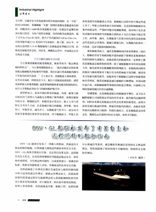
DNV·GL船级社发布了有关自主和远程操作的船舶指南
DNV ·G1 海 书 t, g执 行 I 称 ,见沦其 以决策 支持 、远 程操 软 件 测 试
作或 r1 i 彤 .rI动化 度增强仃 叮能提 高航运 安令 、效率
(刘昭青 编 译 )
】环境 绩效 为实 这 卡L卜可能性 .行业需 要建技术安伞实施 、
I 获 得批 准 该指 南涵 盖 导航 、船 舶 l: 、远 控 制
该指 南削述 脱 仃 法规 以及通常 卜h人操 作控 制功能
I…I听1:适 f{{的 新运 作理 念 就 新运 作理 念 言 ,该指 南 帮
I5 崽 哽 通 过 序 文 施 新 理 念 的 人获 得 舟仆旗 按 替 代 性
没 硬求 埘 的批准 对 j:新技术 ,供 商 町使 该指南 ,
作.I『1i甲板 、通 、 载舱透 气管部分的结冰将 直接 影响 这 没 备的J卜常使 用;船舶牵载航行时 , 载舱 I~的海水一 I{.结冰 .还 有叮能损坏 船体结构
就 北 极 航线 I 言 .通 常 北 极 幽 海域 浮 冰 密度 部在 三 成 以 船舶在没囱‘专业破冰船开道 的前提 下彳}之难在北极海域l~ 长H,.tI ̄J保持 伞速航行 . 此 损失 的航速将 在一定 度JI抵 消北极航道总航 程短的优势 除 r通航船舶本身具有抗冰能 /Jgb,船 需要具有抵 御酷寒的特 殊能 力 北极海域 特有 的 }及 与极 夜现 象对 1:航行安全的 影响也 不容 忽略 极 昼容 易引发船 觉疲劳 ,而檄夜对十船舶航行过程 中的嘹望 影 响 j}常 明显 、随着北极航道通行船舶 的不断增 』JIJ,环境 『u】题 H益I II显 .而船舶碰撞 等事故的风险也 会增 JJu,H莳缺乏 足 够 的 基础 没施 以应 对 油泄 漏 毋 庸置疑 ,往北极 航道 航行 的船舶逐年增 长,这不仅 _人 幅降低船 公刊业欧海运 贸易的经 营成本 .提升航线运输的绩 效 : 时 北极东北航道运营常 态化带来的新变化 ,必将分 流原有通行 航道 的货物 ,降低传统 航线的地位 .由此改变 海洋运输格 局 Lj版 fH永圮目前 ,在北极航道走 ¨常 念化 、规模化运营进程 L卜I的安令风险 .依然 可低估
挪威船级社(DNV)
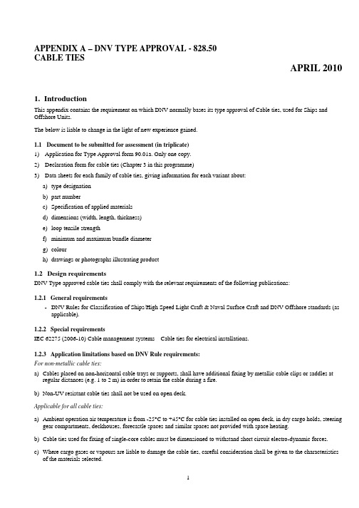
APPENDIX A – DNV TYPE APPROVAL - 828.50CABLE TIESAPRIL 20101.IntroductionThis appendix contains the requirement on which DNV normally bases its type approval of Cable ties, used for Ships and Offshore Units.The below is liable to change in the light of new experience gained.1.1Document to be submitted for assessment (in triplicate)1)Application for Type Approval form 90.01a. Only one copy.2)Declaration form for cable ties (Chapter 3 in this programme)3)Data sheets for each family of cable ties, giving information for each variant about:a)type designationb)part numberc)Specification of applied materialsd)dimensions (width, length, thickness)e)loop tensile strengthf)minimum and maximum bundle diameterg)colourh)drawings or photographs illustrating product1.2Design requirementsDNV Type approved cable ties shall comply with the relevant requirements of the following publications:1.2.1General requirements-DNV Rules for Classification of Ships/High Speed Light Craft & Naval Surface Craft and DNV Offshore standards (as applicable).1.2.2Special requirementsIEC 62275 (2006-10) Cable management systems – Cable ties for electrical installations.1.2.3Application limitations based on DNV Rule requirements:For non-metallic cable ties:a)Cables placed on non-horizontal cable trays or supports, shall have additional fixing by metallic cable clips or saddles atregular distances (e.g. 1 to 2 m) in order to retain the cable during a fire.b)Non-UV resistant cable ties shall not be used on open deck.Applicable for all cable ties:a)Ambient operation air temperature is from -25°C to +45°C for cable ties installed on open deck, in dry cargo holds, steeringgear compartments, deckhouses, forecastle spaces and similar spaces not provided with space heating.b)Cable ties used for fixing of single-core cables must be dimensioned to withstand short circuit electro-dynamic forces.c)Where cargo gases or vapours are liable to damage the cable ties, careful consideration shall be given to the characteristicsof the materials selected.1.3Requirements of identification of product type with certificateThe product is to be provided with visible marking, giving at least the following information:Manufacturer's name or trade mark - Type designation.The marking is to be carried out in such a way that it is visible, legible and indelible throughout the anticipated life of the product, and that the marks can be traced back to the type approval certificate. For smaller products, marking on packing only can be accepted.1.4Test requirementsPlease refer to table of tests chapter 2 and IEC62275.1.4.1How to pick out test samplesThe DNV surveyor at responsible approval centre shall normally pick out test samples.According to IEC62275 each test shall be carried out on a new set of 10 cable ties.The type testing shall be carried out on specimens or productsrepresentative of the production. (the smallest and the largest size in product range, and 1 size in between).2. Table of tests:The cable ties shall be tested according to the requirements in IEC62275.MaterialReference to IEC 62275Type test:M = Mandatory test, V = Voluntary test n/a = Not ApplicableMetallic 6.1.1Non Metallic 6.1.2 Composite 6.1.3Mechanical properties :9.2 Installation testM MM9.3 Minimum installation temperature test n/a 1M M 9.4 Minimum operating temperature testn/a 2M M 9.5Loop tensile strength test for ties retaining 50 % strength after testing (Tests to be performed as received condition, after heat and after temperature cycling)n/aM(9.5 or 9.6)M(9.5 or 9.6)9.6 Loop tensile strength test for ties retaining 100 % strength after testing (Tests to be performed as received condition, after heat, after temperature cycling and vibration 3)M M (9.5 or 9.6)M(9.5 or 9.6)9.7 Mechanical strength test for fixing devices(Tests to be performed as received condition, after heat, after temperature cycling) V V V10 Contribution to fire 4V V V Environmental influences 11.1 Resistance to UV light n/aMM11.2Resistance to corrosion 5M M M1 Compliance by this test is checked for non metallic and composite cable ties only, ref. 9.1.2 Compliance by this test is checked for non metallic and composite cable ties only, ref. 9.1. 3Non-metallic and composite cable ties are considered to be resistant to the effects of vibration, ref. 9.1. 4According to DNV Rules Pt4 Ch8 Sec 3 D103 b) Electrical equipment shall be constructed of at least flame retardant material. Due to limited amount of material, this test is voluntary for cable ties. 5According to DNV Rules Pt4 Ch8 Sec 3 D103 a) Electrical equipment shall be constructed of durable non-hygroscopic materials which are not subject to deterioration in the atmosphere to which it is likely to be exposed.3.Declaration form for cable ties according to IEC 62275 classification: Manufacturer: ____________________________________________________ Family of cable ties: ___________________________________________________Classificationaccording to IEC62275:Options: Please fill in: 6.1 Material: Metallic, Non-metallic or composite6.2 Loop tensile strength: According to Table 2 Info to be given indata sheets.6.2.1 Type 1: Retains 50 % strength after testing, OR6.2.2 Type 2: Retains 100 % strength after testingMaximum operation temperature, ref. Table 3 [ºC]Minimum operation temperature, ref. Table 4 [ºC] 6.3 Temperature:Minimum installation temperature. [ºC]6.4 Contribution to fire: For non-metallic or composite cable ties: Considered tocause minimal contribution to fire due to small amountof material. Metallic cable ties are considerednon-flame propagating.Not necessary todeclare6.5.1 Resistance toUV light:Either resistant to UV light or Not declared(If not UV resistant, an application limitation ‘Not to beused on open deck’ will be added)6.5.2 Resistance to corrosion: Either resistant to corrosion or Not declared Only corrosionresistant cable tiescan be DNV typeapprovedDate: ____________________ Signature: ________________________________。
dnv标准关于抗震的要求
3.弹性与非弹性响应:DNV要求建筑或设施在地震中应表现出弹性行为,即结构在地震后应保持其整体性和稳定性。如果结构进入非弹性区域,则需要进行详细的结构分析和评估,确保其在地震后仍然可以使用。对于抗震的要求,具体取决于建筑或设施的具体应用和所处的地理位置。以下是一些一般性的要求:
1.评估和设计:首先,建筑或设施必须经过仔细的评估,确定其地震风险。这包括了解该地区的历史地震记录、地质构造以及可能的地震活动。基于这些信息,设计团队应进行地震工程设计,确保结构能够承受地震的影响。
4.附加措施:为了提高结构的抗震性能,可能还需要采取一些附加措施,如增加阻尼器、进行土体加固等。
5.紧急设备:为了确保在地震后能够迅速恢复,建筑或设施内应设有紧急设备和措施,例如应急照明、逃生通道等。
这些要求并不是唯一的标准,具体情况可能因不同的标准和规定而有所不同。因此,在进行抗震设计和评估时,应遵循当地的地震工程规范和标准,并咨询专业的地震工程专家或机构。
DNV船级社木质船舶建造与入级规范
DNV船级社木质船舶建造与入级规范1970年1971年11月(附1972年4月修订版)目录第1章一般规则第1节船级社规则页码A. 定义 3B. 另行、等效布置 3C. 补充要求 4D. 规则修订 4E. 适用于指定船级的规则 4第2节船级附加标志A. 主要船级 4B. 有限航区 5C. 特殊用途和具备特殊设备等的船舶 5D. 建造中检验 6第3节指定船级A. 指定船级的申请 6B. 计划等的批准 7C. 检验 7D. 指定船级 8第4节船舶入级的运行控制A. 船东义务 9第5节撤销船级A. 撤销船级的原因 9B. 撤销船级的程序 10第6节其他规则A.总则 10第7节其他基本推定A. 船舶处理 11第2章木质船舶建造规则第1节一般规则和定义页码A. 船级 13B. 参考 13C. 定义 13D. 图纸 14E. 开展工作 14F. 尺度 15第2节材料A. 木质材料 15B. 钢和铝 16第3节叠层结构部件A. 制造叠层部件的胶合工作 16B. 制造叠层部件 17C. 胶合与硬化 17D. 测试 18第4节框架和肋板、舷墙支柱A. 框架间距 18B. 叠层框架、肋板 19C. 双层内建框架和肋板 20D. 舷墙支柱 21第5节龙骨和内龙骨A. 叠层龙骨 22B. 由榫接木材制成的龙骨和内龙骨 22C. 由钢材制成的龙骨和内龙骨 23D. 槽口 23第6节船首材、尾柱和尾框底部A. 木质船首材和尾柱 23B. 尾框底部 24第7节桁材A. 胶合叠层框架上的桁材 25B. 双层内建框架上的桁材 26第8节甲板横梁夹具、承梁材和铺板页码A. 甲板横梁夹具和承梁材 26B. 内壳面板或铺板 26第9节横梁、甲板纵桁和支柱A. 横梁 27B. 甲板纵桁 27C. 支柱 28第10节肘材和肋骨支架,船首船尾肘材A. 水平肘材 28B. 悬挂肘材和肋骨支架 29C. 船首船尾肘材 29第11节外壳面板和甲板A. 外壳面板 29B. 甲板 30C. 捻缝和密性测试 30第12节机舱和外壳A. 机舱 31B. 外壳 32第13节不构成部分机舱外壳的甲板室和上层建筑A. 钢或铝结构 33第14节船体开口关闭装置、舱口围板和舱口盖、甲板泄水口A. 一般要求 34B. 上层建筑和甲板室的关闭装置和静止高度 34C. 甲板开口 35D. 舱口盖的关闭和系固 36E. 机舱外壳的开口 37F. 升降口 38G. 舷窗 38H. 通风口、空气管和测深管 38I. 卫生排放口 39 J. 泄水口 40 K. 舷墙排水口 40第15节钢和铝的焊接页码A. 焊接尺寸 41第16节舱壁A. 一般要求 42B. 货舱内永久性木质舱壁 42第17节螺栓连接和钉子连接A. 一般要求 43B. 龙骨、框架、梁夹具、肘材等的螺栓连接 43C. 框架和肋板的螺栓连接 45D. 面板和甲板的螺栓和钉子连接 46第18节捕海豹船A. 一般要求 47B. 框架、肋板和甲板横梁 47C. 肘材和肋骨支架、船首船尾肘板 48D. 外壳与内壳面板 48E. 桁材和货舱横梁 49F. 其他加强 49第19节渔船A. 一般规则 49第III章船舶入级的运行控制第1节船级维护的检验A. 一般要求 51B. 定期检验 53C. 延迟定期检验的目测检验 55图纸、图表和表格页码图纸图1 垂线和船舶长度L的定义 59 图2 传统船舶的船中剖面 59 图3 连接内龙骨/船尾 60 图4A和B “直线”框架长度Lo的定义以及曲线高度f 61 图4C和D 确定尺度的框架长度的定义 62 图5 面板的重叠 63图表图6A )图6B )矩形剖面的剖面模数 64 图6C )图7 法兰钢肋板的剖面模数 67表格表1 双层内建框架。
船级社(Classification

船级社(Classification society)船级社(Classification society)船级社是⼀个建⽴和维护船舶和离岸设施建造和操作技术标准的⾮政府组织。
通常通过对于船舶监造和定期检查来确保航海设备满⾜其规范。
责任船级社设定技术规范,确认船舶和其他航海设备设计满⾜规范要求。
在船舶建造和调试期间进⾏监控,并在设备和船舶运营期内进⾏持续检查以确保船舶和设施持续符合规范要求。
船级社同样对于⽯油平台,离岸设施和潜艇进⾏船检。
船检过程涉及的柴油发动机,重要的舰载泵和其他重要机械。
验船师进⾏船检以确保该船舶,其设备和机械建造以及维护符合其⼊级船级社的规范要求。
历史⼗⼋世纪中,伦敦的商⼈,船东和船长经常聚集在爱德华劳埃德(Edward Lloyds)咖啡馆谈论⼋卦,分享航⾏见闻已经从事交易。
⼤部分的船舶和货物保险都在此地办理。
不久,保险业就意识到需要对于船舶的质量进⾏了解。
在1760年注册协会成⽴,发展成世界上第⼀个船级社劳⽒船级社,并开始对船舶开始检验和登记⼊级,并开始对于船舶和设备进⾏分类。
当时将船体技术状况划分为五类:A(最好)、E(较好)、I(中等)、O(较坏)、U(最坏);⼜将所帆、锚等设备分为三类:G(好)、 M(中)、B(坏)。
随着时间的推移,G、M和B被1,2,3所替代。
这也是现在众所周知的代表最⾼等级的 A1的由来。
该系统的⽬的是,对船舶安全性,适航性的风险评估。
劳⽒船级社在1764年出版了第⼀版船舶登记簿,并在1764年到1766年间使⽤。
必维船级社(Bureau Veritas)与1828年在安特卫普成⽴,并与1832年搬迁到巴黎。
其他船级社§ 美国船级社 ABS American Bureau of Shipping§ 法国船级社 BV Bureau Veritas§ 中国船级社 CCS China Classification Society§ 中国验船中⼼ CR China Corporation Register of Shipping§ 挪威船级社 DNV Det Norske Veritas§ 德国劳⽒船级社 GL Germanischer Lloyd§ 韩国船级社 KR Korean Register of Shipping§ 英国劳⽒船级社 LR Lloyd's Register§ ⽇本海事协会 NK Nippon Kaiji Kyokai (ClassNK)§ 意⼤利船级学会 RINA Registro Italiano Navale§ 俄罗斯船级社 RS Russian Maritime Register of ShippingA classification society is a nongovernment organization that establishes and maintains technical standards for the construction and operation of ships and off shore structure. The society will also validate that construction is according to these standards and carry out regular surveys in service to ensure compliance with the standards.ResponsibilityClassification societies set technical rules, confirm that designs and calculations meet these rules, survey ships and structures during the process of construction and commissioning, and periodically survey vessels to ensure that they continue to meet the rules. Classification societies are also responsible for classing oil platform, other offshore structures, and submarines. This survey process covers diesel engines, important shipboard pumps and other vital machinery. Classification surveyors inspect ships to make sure that the ship, its components and machinery are built and maintained according to the standards required for their class.HistoryIn the second half of the 18th century, London merchants, ship-owners, and captains often gathered at Edward Llord coffee house to gossip and make deals including sharing the risks and rewards of individual voyages. This became known as underwriting after the practice of signing one's name to the bottom of a document pledging to make good a portion of the losses if the ship didn’t make it in return for a portion of the profits. It did not take long to realize that the underwriters needed a way of assessing the quality of the ships that they were being asked to insure. In 1760, the Register Society was formed —the first classification society and which would subsequently become Llord's Register — to publish an annual register of ships. This publication attempted to classify the condition of the ship’s hull and equipment. At that time, an attempt was made to classify the condition of each ship on an annual basis. The condition of the hull was classified A, E, I, O or U, according to the state of its construction and its adjudged continuing soundness (or lack thereof). Equipment was G, M, or B: simply, good, middling or bad. In time, G, M and B were replaced by 1, 2 and 3, which is the origin of the well-known expression 'A1', meaning 'first or highest class'. The purpose of this system was not to assess safety, fitness for purpose or seaworthiness of the ship. It was to evaluate risk.Samuel Plimsoll pointed out the obvious downside of insurance:The ability of ship-owners to insure themselves against the risks they take not only with their property, but with other peoples’lives, is itself the greatest threat to the safe operation of ships.The first edition of the Register of Ships was published by Lloyd's Register in 1764 and was for use in the years 1764 to 1766.Bureau Veritas (BV) was founded in Anwert in 1828, moving to Paris in 1832. Lloyd's Register reconstituted in 1834 to become 'Lloyd's Register of British and Foreign Shipping'. Where previously surveys had been undertaken by retired sea captains, from this time surveyors started to be employed and Lloyd's Register formed a General Committee for the running of the Society and for the Rules regarding ship construction and maintenance, which began to be published from this time.In 1834, the Register Society published the first Rules for the survey and classification of vessels, and changed its name to Lloyds Register of Shipping. A full time bureaucracy of surveyors (inspectors) and support people was put in place. Similar developments were taking place in the other major maritime nations.Adoption of common rules for ship construction by Norwegian insurance societies in the late 1850s led to the establishment of Det Norske veritas (DNV) in 1864. Then after RINA was founded in Genoa, Italy in 1861 under the name Registro Italiano, to meet the needs of Italian maritime operators. Six years later Germanischer Lloyd (GL) was formed in 1867 and Nippon Kaiji Kyokai (ClassNK) in 1899. The Russian Maritime Register of Shipping (RS) was an early offshoot of the River Register of 1913.As the classification profession evolved, the practice of assigning different classifications has been superseded, with some exceptions. Today a ship either meets the relevant class society’s rules or it does not. As a consequence it is either 'in' or'out' of 'class'. Classification societies do not issue statements or certifications that a vessel is 'fit to sail' or 'unfit to sail', merely that the vessel is in compliance with the required codes. This is in part related to legal liability of the classification society.However, each of the classification societies has developed a series of notations that may be granted to a vessel to indicate that it is in compliance with some additional criteria that may be either specific to that vessel type or that are in excess of the standard classification requirements. See Ice class as an example.。
DNV挪威船级社规范中文版
第2节 规范的范围和船级符号 ................. 8
A. 规范的应用 规范的应用范围 应用范围 ............................... 8 A 100 一般要求 .................................. 8 A 200 规范的应用范围 ............................. 8 A 300 规范的要点 ................................ 8 B. 船级符号 ................................ ..................................... ..... 9 B 100 一般要求 .................................. 9 B 200 建造符号 .................................. 9 B 300 船级主字符 ............................... 9 B 400 航区船级符号 .............................. 9 B 500 其它航行限制 .............................. 9 B 600 附加船级: 服务和类型船级符号 ............. 9 B 700 附加船级: 设备和系统船级符号 .............. 12 B 800 附加船级: 特征船级符号 .................... 14 B 900 国家法规 .................................. 14 B 1000 附加船级: NAUTICUS ........................ 14
的服务范围,且涉及: — 无论是新建造的或营运船舶的入级; — 代表国家海事主管机关执行的法定检验工作; — 船用设备和材料。
【船检规范】dnv+rule+船舶入级规范+材料和焊接1

船舶入级规范船舶船舶//高速高速、、轻型船只和海军水面舰艇新建船舶材料和焊接第 2 篇 第 1 章材料的一般性要求2003年1月本册包括第0篇第1章第3节2006年1月版本中所示的相关的增补和更正内容第1节 制造、检验和认证 ........................................................5 第2节 试验程序 . (7)挪威船级社Veritasveien 1, NO-1322 Høvik, Norway Tel.: +47 67 57 99 00 Fax: +47 67 57 99 11规范更改说明综述综述理事会于2002年12月确定了包括增补内容在内的现行规范版本,并以此替换本章的1993年1月版。
本规范的更改于2003年7月1日生效.本章在被新的修订版代替之前有效。
仅在第0篇第1章第3节刊登少量增补和更正的更新后清单以外,不发行修正版。
第0篇第1章通常于每年的1月及7月修订。
修改过的各章将发给本规范的所有订户。
建议重印版本的购买者核对在第0篇第1章第1节给出的中规范各章的更新后的清单,以确认该章为现行版本。
主要更改主要更改· 第一节第一节 -制造制造、、检验和认证检验和认证— 301被修改为包括“需要提供NV或工厂证书”的文字叙述— 条款A301经修订后,其含义表示经认可的制造厂可以在互联网上的DNV Exchange中查询到。
· 第2节-试验程序试验程序— 删除图5和图6“Z向拉伸试验试样示例”。
— 删除子节B500 "Z向延展性试验" 。
— B600 被重新编号为B500。
— B700被重新编号为B600。
更正和澄清更正和澄清..除了上述的规范要求外,对现有的规范文字内容进行了一些错误删除、更正和澄清。
针对规范的意见可以通过电子邮件发送至rules@有关订购或订阅事项的信息,请联系distribution@有关DNV和本社服务的全面信息,请访问网址© Det Norske Veritas 挪威船级社由挪威船级社计算机排版(FM+SGML)挪威印刷可以证明的因挪威船级社过失的作为和不作为所致,对任何人造成的损失或损坏,挪威船级社赔偿其可以证明的直接损失或损坏。
DNV船级社认证过程相关工作
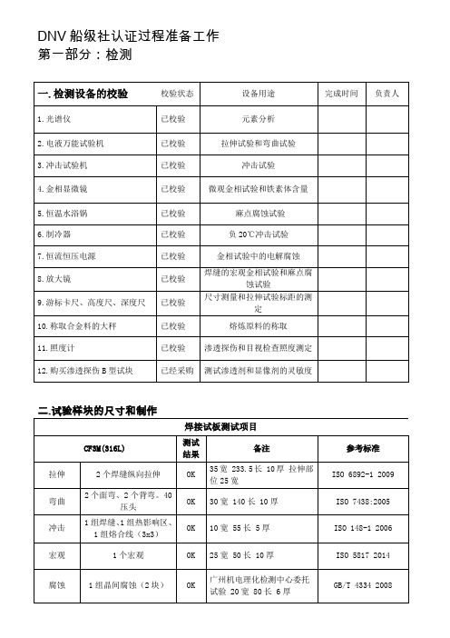
ASTM A370 2014
冲击
零下196℃冲击
OK
10宽 10厚 55长
ASTM A370 2014
微观
2个微观金相,表面和中间
OK
25宽 50长 10厚
GB/T 13298-2015
腐蚀
2个晶间腐蚀,从拉伸试棒中取样
OK
70长 10宽 5厚
GB/T 4334 2008
受控的外来文件
已完成
二.生产流程相关准备
A.需要认证产品的工艺情况
名称
材质
单重
串重
工艺情况
铸件尺寸情况
备注
图纸情况
5A
17.82
36.81
工艺OK
尺寸OK
一炉4件+拉伸、冲击、腐蚀;产品熔炼工艺卡已经调整完毕
铸件图、蜡模图齐全
5A
122.4
235.4
工艺已经调整
尺寸OK
一炉1件+拉伸、冲击、腐蚀;产品熔炼工艺卡已经调整完毕
已校验
金相试验中的电解腐蚀
8.放大镜
已校验
焊缝的宏观金相试验和麻点腐蚀试验
9.游标卡尺、高度尺、深度尺
已校验
尺寸测量和拉伸试验标距的测定
10.称取合金料的大秤
已校验
熔炼原料的称取
11.照度计
已校验
渗透探伤和目视检查照度测定
12.购买渗透探伤B型试块
已经采购
测试渗透剂和显像剂的灵敏度
二.试验样块的尺寸和制作
受控中
已完成
双相不锈钢铸件焊补作业指导书
受控中
已完成
检测标准
ASTM A351/A351M 2012
ts410DNV船级社入级规范2006版
RULES FOR CLASSIFICATION OFD ET N ORSKE V ERITASVeritasveien 1, NO-1322 Høvik, Norway Tel.: +47 67 57 99 00 Fax: +47 67 57 99 11SHIPSNEWBUILDINGSMACHINERY AND SYSTEMSMAIN CLASS PART 4 CHAPTER 10FIRE SAFETYJULY 2004CONTENTS PAGESec.1General Requirements (5)Sec.2Fire Safety Measures for Cargo Ships of Less Than 500 Gross Tonnage (9)Sec.3Fire Safety Measures for Cargo Ships of 500 Gross Tonnage and Above (11)Sec.4Fire Safety Measures for Issue of SOLAS Safety Certificates (13)App.A Interpretations and Clarifications to SOLAS Ch. II-2 (15)App.B Fixed Gas Fire-extinguishing Systems (22)App.C High Expansion and Inside Air Foam Systems (25)INTRODUCTIONComments to the rules may be sent by e-mail to rules@For subscription orders or information about subscription terms, please use distribution@Comprehensive information about DNV and the Society's services is found at the Web site © Det Norske VeritasComputer Typesetting (FM+SGML) by Det Norske Veritas Printed in NorwayIf any person suffers loss or damage which is proved to have been caused by any negligent act or omission of Det Norske Veritas, then Det Norske Veritas shall pay compensation to such person for his proved direct loss or damage. However, the compensation shall not exceed an amount equal to ten times the fee charged for the service in question, provided that the maximum compen-sation shall never exceed USD 2 million.In this provision "Det Norske Veritas" shall mean the Foundation Det Norske Veritas as well as all its subsidiaries, directors, officers, employees, agents and any other acting on behalf of Det Norske Veritas.GeneralThe Executive Board approved this new chapter in June 2004. These rules come into force on 1 January 2005.This chapter is valid until superseded by a revised chapter. Supple-ments will not be issued except for an updated list of minor amend-ments and corrections presented in Pt.0 Ch.1 Sec.3. Pt.0 Ch.1 is normally revised in January and July each year.Revised chapters will be forwarded to all subscribers to the rules.Buyers of reprints are advised to check the updated list of rule chap-ters printed Pt.0 Ch.1 Sec.1 to ensure that the chapter is current.IntroductionThis new chapter is moved from Pt.3 Ch.3 Sec.10.In addition, DNV guidelines/interpretations on fire safety issues, e.g.for extinguishing systems, have been reintroduced in the rules.DNV guidelines/interpretations to SOLAS Ch.II-2, plus all relevant IACS interpretations to Ch.II-2 have been reinserted in the rules as ap-pendices, being an implicit part of DNV's scope when so authorised by the flag administration to issue SOLAS Safety Certificates.DNV's interpretations of SOLAS on high expansion foam extinguish-ing systems have also been updated and aligned with accepted indus-try standards as of today.Main class fire safety rules for cargo vessels < 500 gross tonnage have been updated to be in line with IACS Internal Guideline No.2 for small vessels.Rules for Ships, July 2004Pt.4 Ch.10 Contents – Page 3D ET N ORSKE V ERITASCONTENTSSEC. 1GENERAL REQUIREMENTS.......................... 5A.Application.. (5)A 100Application (5)B.Scope of Work (5)B 100Classification.....................................................................5B 200SOLAS safety certificates. (5)C.Submission of Documentation (5)C 100General (5)D.Definitions (5)D 100Definitions (5)SEC. 2FIRE SAFETY MEASURES FOR CARGOSHIPS OF LESS THAN500 GROSS TONNAGE....................................... 9A.General.. (9)A 100Application........................................................................9A 200Submission of documentation. (9)B.Suppression of Fire (9)B 100Fire pumps ........................................................................9B 200Fire mains and hydrants....................................................9B 300Fire extinguishers..............................................................9B 400Fixed fire-extinguishing systems....................................10B 500Cargo tank protection......................................................10B 600Fire-fighter’s outfits........................................................10B700Structural fire protection.................................................10C.Escape.. (10)C 100Means of escape (10)SEC. 3FIRE SAFETY MEASURES FOR CARGOSHIPS OF 500 GROSS TONNAGEAND ABOVE....................................................... 11A.General (11)A 100Application......................................................................11A 200Submission of documentation (11)B.Means of Escape (11)B 100General............................................................................11B 200Means of escape from accommodation spaces, service spaces and control stations..............................................11B 300Means of escape from machinery spaces........................11B 400Means of escape from ro-ro spaces.................................12C.Fire Control Plans (12)C 100Fire control plans (12)SEC. 4FIRE SAFETY MEASURES FOR ISSUEOF SOLAS SAFETY CERTIFICATES........... 13A.General (13)A 100Application......................................................................13A 200Purpose............................................................................13A 300Scope...............................................................................13A 400Submission of documentation (13)APP. A INTERPRETATIONS AND CLARIFICATIONS TO SOLAS CH. II-2.......................................................... 15A.General (15)A 100Application (15)B.SOLAS Reg.II-2/4 Probability of Ignition (15)B 100Miscellaneous items of ignition sourcesand ignitability (15)C.SOLAS Reg.II-2/5 Fire Growth Potential (15)C 100Control of air supply and flammable liquidto the space......................................................................15C 200Fire protection materials (15)D.SOLAS Reg.II-2/6 Smoke Generation Potential andToxicity (17)D 100Paints, varnishes and other finishes, primary deckcoverings (17)E.SOLAS Reg.II-2/7 Detection and Alarm (17)E 100General requirements......................................................17E 200Protection of machinery spaces......................................17E 300Protection of accommodation and service spaces and control stations................................................................17E 400Requirements of the FSS Code Ch. 9 Fixed firedetection and fire alarm systems.....................................18F.SOLAS Reg.II-2/8 Control of Smoke Spread (18)F 100Protection of control stations outsidemachinery spaces (18)G.SOLAS Reg.II-2/9 Containment of Fire (18)G 100Thermal and structural boundaries..................................18G 200Protection of openings in fire-resisting divisions ..........18G 300Protection of openings in machinery spaceboundaries.......................................................................18G 400Ventilation systems (18)H.SOLAS Reg.II-2/10 Fire Fighting (19)H 100Water supply systems.....................................................19H 200Portable fire extinguishers..............................................19H 300Fixed fire-extinguishing systems....................................19H 400Fire-extinguishing arrangements in machinery spaces...20H 500Fire-extinguishing arrangements in cargo spaces...........20H 600Fire-fighter’s outfits (20)I.SOLAS Reg.II-2/11 Structural Integrity..........................20J.SOLAS Reg.II-2/12 Notification of Crewand Passengers....................................................................20K.SOLAS Reg.II-2/13 Means of Escape. (20)K 100Means of escape from control stations,accommodation spaces and service spaces.....................20K 200Means of escape from machinery spaces (20)L.SOLAS Reg.II-2/14 Operational Readiness andMaintenance........................................................................20M.SOLAS Reg.II-2/15 Instructions, Onboard Trainingand Drills.............................................................................21N.SOLAS Reg.II-2/16 Operations........................................21O.SOLAS Reg.II-2/17 Alternative Designand Arrangements..............................................................21P.SOLAS Reg.II-2/18 Helicopter Facilities. (21)P 100Helicopter refuelling and hangar facilities (21)Q.SOLAS Reg.II-2/19 Carriage of Dangerous Goods (21)Q 100General (21)R.SOLAS Reg.II-2/20 Protection of Vehicle, SpecialCategory and Ro-Ro Spaces (21)R 100Precaution against ignition of flammable vapours in closed vehicle spaces, closed ro-ro spaces andspecial category spaces (21)APP. B FIXED GAS FIRE-EXTINGUISHINGSYSTEMS 22A.General (22)A 100Application (22)B.Requirements for all Gas Fire-extinguishing Systems (22)B 100General requirements .....................................................22C.CO 2 Fire-extinguishing Systems (22)C 100General requirements (22)Rules for Ships, July 2004Pt.4 Ch.10 Contents – Page 4D ET N ORSKE V ERITASC 200Fire-extinguishing systems for cargo holds....................22C 300CO 2 high pressure fire-extinguishing systems formachinery spaces............................................................22D.Low Pressure CO 2 Systems . (23)D 100General............................................................................23D 200Testing (24)APP. C HIGH EXPANSION AND INSIDE AIRFOAM SYSTEMS (25)A.General (25)A 100Application .....................................................................25A 200Water and foam concentrate supply systems..................25A 300Foam generating components and foamgenerator room................................................................25A 400System arrangement........................................................25A 500Arrangement for machinery spaces andcargo pump rooms...........................................................26A 600Arrangement for ro-ro spaces (26)Rules for Ships, July 2004Pt.4 Ch.10 Sec.1 – Page 5D ET N ORSKE V ERITASSECTION 1GENERAL REQUIREMENTSA. ApplicationA 100Application101 Unless explicitly stated, the requirements of this chapter do not apply to: —ships of war and troopships—ships not propelled by mechanical means —wooden ships of primitive build —pleasure yachts not engaged in trade —fishing vessels.B. Scope of WorkB 100Classification101 The requirements in Sec.2 apply to cargo ships of less than 500 gross tonnage assigned main class.102 The requirements in Sec.3 apply to cargo ships of 500gross tonnage and above assigned main class.103 Supplementary requirements will be enforced for ships with additional class notations as required by the respective parts of the rules.Guidance note:Other requirements in Pt.1, Pt.2, Pt.3 and Pt.4 may apply in addi-tion to these rules.---e-n-d---of---G-u-i-d-a-n-c-e---n-o-t-e---B 200SOLAS safety certificates201 It is the responsibility of the government of the flag state to ensure that ships are provided with the fire safety measures required by the International Convention for the Safety of Life at Sea, 1974, as amended (hereafter referred as SOLAS) when such requirements apply.202 Where the government of the flag state has authorised the Society to issue the SOLAS safety certificates on its behalf,the Society will give effect to the fire protection, detection and extinction requirements of Ch.II-2 of SOLAS.203 The requirements in Sec.4 apply as the basis for stating compliance with Ch.II-2 of SOLAS and as part of the basis for the issue of SOLAS safety certificates. Compliance with re-quirements in Sec.4 will automatically result in compliance with requirements in Sec.3 for assignment of main class.C. Submission of DocumentationC 100General101 Verification of design is based on an assessment of plans and documentation containing relevant information elements.102 Plans and documentation shall be submitted for assess-ment as required by Sec.2, Sec.3 and Sec.4 respectively de-pending on the Society’s scope of work.D. DefinitionsD 100Definitions101 Accommodation spaces are those spaces used for public spaces, corridors, lavatories, cabins, offices, hospitals, cine-mas, game and hobby rooms, barber shops, pantries containing no cooking appliances and similar spaces.(SOLAS Ch. II-2/3.1).102 “A” class divisions are those divisions formed by bulk-heads and decks which comply with the following criteria:—they are constructed of steel or other equivalent material —they are suitably stiffened—they are insulated with approved non-combustible materi-als such that the average temperature of the unexposed side will not rise more than 140°C above the original tem-perature, nor will the temperature, at any one point, includ-ing any joint, rise more than 180°C above the original temperature, within the time listed below:—they are so constructed as to be capable of preventing thepassage of smoke and flame for the full duration of the one-hour standard fire test—the Society shall require a test of a prototype bulkhead ordeck in accordance with the Fire Test Procedures Code to ensure that it meets the above requirements for integrity and temperature rise.(SOLAS Ch. II-2/3.2)103 Atriums are public spaces within a single main vertical zone spanning three or more open decks.(SOLAS Ch. II-2/3.3)104 “B” class divisions are those divisions formed by bulk-heads, decks, deckheads or linings, which comply with the fol-lowing criteria:—they are constructed of approved non-combustible materi-als and all materials used in the construction and erection of "B" class divisions shall be non-combustible, with the exception that combustible veneers may be permitted pro-vided they meet other requirements of this chapter—they have an insulation value such that the average tem-perature of the unexposed side will not rise more than 140°C above the original temperature, nor will the temper-ature at any one point, including any joint, rise more than 225°C above the original temperature, within the time list-ed below:—they are so constructed as to be capable of preventing thepassage of flame to the end of the first half hour of the standard fire test—the Society shall require a test of a prototype division inaccordance with the Fire Test Procedures Code to ensure that it meets the above requirements for integrity and tem-perature rise.(SOLAS Ch. II-2/3.4)105 Bulkhead deck is the uppermost deck up to which the transverse watertight bulkheads are carried.(SOLAS Ch. II-2/3.5)–class "A-60"60 minutes –class "A-30"30 minutes –class "A-15"15 minutes –class "A-0"0 minutes–class "B-15"15 minutes –class "B-0" 0 minutesRules for Ships, July 2004Pt.4 Ch.10 Sec.1 – Page 6D ET N ORSKE V ERITAS106 Cargo area is that part of the ship that contains cargo holds, cargo tanks, slop tanks and cargo pump-rooms includ-ing pump-rooms, cofferdams, ballast and void spaces adjacent to cargo tanks and also deck areas throughout the entire length and breadth of the part of the ship over the above mentioned spaces.(SOLAS Ch. II-2/3.6)107 A cargo ship is any ship that is not a passenger ship.(SOLAS Ch. I/2(g))108 Cargo spaces are spaces used for cargo, cargo oil tanks,tanks for other liquid cargo and trunks to such spaces.(SOLAS Ch. II-2/3.8)109 Central control station is a control station in which the following control and indicator functions are centralised:—fixed fire detection and fire alarm system—automatic sprinklers, fire detection and fire alarm system —fire door indicator panels —fire door closure—watertight door indicator panels —watertight door closure —ventilation fans —general/fire alarms—communication systems including telephones —microphones to public address systems.(SOLAS Ch. II-2/3.9)110 “C” class divisions are divisions constructed of ap-proved non-combustible materials. They need meet neither re-quirements relative to the passage of smoke and flame nor limitations relative to the temperature rise. Combustible ve-neers are permitted provided they meet other requirements of this chapter.(SOLAS Ch. II-2/3.10)111 A division consisting of a non-combustible core and combustible veneers may be accepted as a B or C class divi-sion, provided that the non-combustible core is tested in ac-cordance with the Fire Test Procedures Code, part 1, that the B class division is tested in accordance with the Fire Test Proce-dures Code, part 3, and that the veneers mounted to the non-combustible core are tested in accordance with the Fire Test Procedures Code, part 5 and part 2 if applicable. (IACS UI SC125)112 Chemical tanker is a cargo ship constructed or adapted and used for the carriage in bulk of any liquid product of a flammable nature listed in chapter 17 of the International Bulk Chemical Code, as defined in regulation VII/8.1.(SOLAS Ch. II-2/3.11)113 Closed ro-ro spaces are ro-ro spaces which are neither open ro-ro spaces nor weather decks.(SOLAS Ch. II-2/3.12)114 Closed vehicle spaces are vehicle spaces which are nei-ther open vehicle spaces nor weather decks.(SOLAS Ch. II-2/3.13)115 Combination carrier is a cargo ship designed to carry both oil and solid cargoes in bulk.(SOLAS Ch. II-2/3.14)116 Combustible material is any material other than a non-combustible material.(SOLAS Ch. II-2/3.15)117 Continuous “B” class ceilings or linings are those "B"class ceilings or linings which terminate at an "A" or "B" class division.(SOLAS Ch. II-2/3.16)118 Continuously manned central control station is a central control station which is continuously manned by a responsible member of the crew.(SOLAS Ch. II-2/3.16)119 Control stations are those spaces in which the ship's ra-dio or main navigating equipment or the emergency source of power is located or where the fire recording or fire control equipment is centralized. Spaces where the fire recording or fire control equipment is centralized are also considered to be a fire control station .(SOLAS Ch. II-2/3.18)Control stations are spaces containing emergency sources for emergency lighting, wheel house and chartroom, spaces con-taining the ship's radio equipment, fire-extinguishing rooms.Spaces containing the following battery sources shall be re-garded as control stations regardless of battery capacity:—emergency batteries in separate battery room for powersupply from blackout till start of emergency generator —emergency batteries in separate battery room as reservesource of energy to radiotelegraph installation —batteries for start of emergency generator—and in general, all emergency batteries required in pursu-ance of Ch.8 Sec.2 C.(IACS UI SC17)120 Crude oil is any oil occurring naturally in the earth whether or not treated to render it suitable for transportation and includes crude oil where certain distillate fractions may have been removed from or added to.(SOLAS Ch. II-2/3.19)121 Dangerous goods are those goods referred to in regula-tion VII/2.(SOLAS Ch. II-2/3.20)122 Deadweight is the difference in tonnes between the dis-placement of a ship in water of a specific gravity of 1.025 at the load waterline corresponding to the assigned summer free-board and the lightweight of the ship. (SOLAS Ch. II-2/3.21)123 Fire Safety Systems Code means the International Code for Fire Safety Systems as adopted by the Maritime Safety Committee of the Organization by resolution MSC.98(73), as may be amended by the Organization, provided that such amendments are adopted, brought into force and take effect in accordance with the provisions of article VIII of the present Convention concerning the amendment procedures applicable to the annex other than chapter I thereof.(SOLAS Ch. II-2/3.22)124 Fire Test Procedures Code means the International Code for Application of Fire Test Procedures as adopted by the Maritime Safety Committee of the Organization by resolution MSC.61(67), as may be amended by the Organization, provid-ed that such amendments are adopted, brought into force and take effect in accordance with the provisions of article VIII of the present Convention concerning the amendment procedures applicable to the annex other than chapter I thereof.(SOLAS Ch. II-2/3.23)125 Flashpoint is the temperature in degrees Celsius (closed cup test) at which a product will give off enough flammable vapour to be ignited, as determined by an approved flashpoint apparatus.(SOLAS Ch. II-2/3.24)Rules for Ships, July 2004Pt.4 Ch.10 Sec.1 – Page 7D ET N ORSKE V ERITAS126 Gas carrier is a cargo ship constructed or adapted and used for the carriage in bulk of any liquefied gas or other prod-ucts of a flammable nature listed in chapter 19 of the Interna-tional Gas Carrier Code, as defined in regulation VII/11.1.(SOLAS Ch. II-2/3.25)127 Helideck is a purpose-built helicopter landing area locat-ed on a ship including all structure, fire-fighting appliances and other equipment necessary for the safe operation of heli-copters.(SOLAS Ch. II-2/3.26)128 Helicopter facility is a helideck including any refuelling and hangar facilities.(SOLAS Ch. II-2/3.27)129 Lightweight is the displacement of a ship in tonnes with-out cargo, fuel, lubricating oil, ballast water, fresh water and feedwater in tanks, consumable stores, and passengers and crew and their effects.(SOLAS Ch. II-2/3.28)130 Low flame-spread means that the surface thus described will adequately restrict the spread of flame, this being deter-mined in accordance with the Fire Test Procedures Code.(SOLAS Ch. II-2/3.29)131 Machinery spaces are machinery spaces of category A and other spaces containing propulsion machinery, boilers, oil fuel units, steam and internal combustion engines, generators and major electrical machinery, oil filling stations, refrigerat-ing, stabilizing, ventilation and air conditioning machinery,and similar spaces, and trunks to such spaces.(SOLAS Ch. II-2/3.30)132 Machinery spaces of category A are those spaces and trunks to such spaces which contain either:—internal combustion machinery used for main propulsion —internal combustion machinery used for purposes otherthan main propulsion where such machinery has in the ag-gregate a total power output of not less than 375 kW—any oil-fired boiler or oil fuel unit, or any oil-fired equip-ment other than boilers, such as inert gas generators, incin-erators.(SOLAS Ch. II-2/3.31)133 Main vertical zones are those sections into which the hull, superstructure and deckhouses are divided by "A" class divisions, the mean length and width of which on any deck does not in general exceed 40 m.(SOLAS Ch. II-2/3.32)134 Non-combustible material is a material which neither burns nor gives off flammable vapours in sufficient quantity for self-ignition when heated to approximately 750°C, this be-ing determined in accordance with the Fire Test Procedures Code.(SOLAS Ch. II-2/3.33)135 Oil fuel unit is the equipment used for the preparation of oil fuel for delivery to an oil-fired boiler, or equipment used for the preparation for delivery of heated oil to an internal combus-tion engine, and includes any oil pressure pumps, filters and heaters dealing with oil at a pressure of more than 0.18 N/mm 2.(SOLAS Ch. II-2/3.34)Oil fuel unit includes any equipment used for the preparation and delivery of oil fuel, heated or not, to boilers (including in-ert gas generators) and engines (including gas turbines) at a pressure of more than 0.18 N/mm 2.(IACS UI SC16)136 Open ro-ro spaces are those ro-ro spaces that are either open at both ends or have an opening at one end, and are pro-vided with adequate natural ventilation effective over their en-tire length through permanent openings distributed in the side plating or deckhead or from above, having a total area of at least 10% of the total area of the space sides.(SOLAS Ch. II-2/3.35)137 Open vehicle spaces are those vehicle spaces either open at both ends, or have an opening at one end and are provided with adequate natural ventilation effective over their entire length through permanent openings distributed in the side plat-ing or deckhead or from above, having a total area of at least 10% of the total area of the space sides.(SOLAS Ch. II-2/3.36)138 A passenger ship is a ship which carries more than twelve passengers.(SOLAS Ch. I/2(f))139 Prescriptive requirements means the construction char-acteristics, limiting dimensions, or fire safety systems speci-fied in the rules.(SOLAS Ch. II-2/3.38)140 Public spaces are those portions of the accommodation which are used for halls, dining rooms, lounges and similar permanently enclosed spaces.(SOLAS Ch. II-2/3.39)141 Rooms containing furniture and furnishings of restricted fire risk , are those rooms containing furniture and furnishings of restricted fire risk (whether cabins, public spaces, offices or other types of accommodation) in which:—case furniture such as desks, wardrobes, dressing tables,bureaux, dressers, are constructed entirely of approved non-combustible materials, except that a combustible ve-neer not exceeding 2 mm may be used on the working sur-face of such articles—free-standing furniture such as chairs, sofas, tables, areconstructed with frames of non-combustible materials —draperies, curtains and other suspended textile materialshave qualities of resistance to the propagation of flame not inferior to those of wool having a mass of mass 0.8 kg/m2,this being determined in accordance with the Fire Test Procedures Code—floor coverings have low flame-spread characteristics;—exposed surfaces of bulkheads, linings and ceilings havelow flame-spread characteristics—upholstered furniture has qualities of resistance to the ig-nition and propagation of flame, this being determined in accordance with the Fire Test Procedures Code—bedding components have qualities of resistance to the ig-nition and propagation of flame, this being determined in accordance with the Fire Test Procedures Code.(SOLAS Ch. II-2/3.40)142 Ro-ro spaces are spaces not normally subdivided in any way and normally extending to either a substantial length or the entire length of the ship in which motor vehicles with fuel in their tanks for their own propulsion and/or goods (packaged or in bulk, in or on rail or road cars, vehicles (including road or rail tankers), trailers, containers, pallets, demountable tanks or in or on similar stowage units or other receptacles) can be load-ed and unloaded normally in a horizontal direction.(SOLAS Ch. II-2/3.41)143 Ro-ro passenger ship means a passenger ship with ro-ro spaces or special category spaces.(SOLAS Ch. II-2/3.42)Rules for Ships, July 2004Pt.4 Ch.10 Sec.1 – Page 8D ET N ORSKE V ERITAS144 Steel or other equivalent material means any non-com-bustible material which, by itself or due to insulation provided,has structural and integrity properties equivalent to steel at the end of the applicable exposure to the standard fire test (e.g. alu-minium alloy with appropriate insulation).(SOLAS Ch. II-2/3.43)145 Sauna is a hot room with temperatures normally varying between 80º-120ºC where the heat is provided by a hot surface (e.g. by an electrically-heated oven). The hot room may also include the space where the oven is located and adjacent bath-rooms.(SOLAS Ch. II-2/3.44)146 Service spaces are those spaces used for galleys, pantries containing cooking appliances, lockers, mail and specie rooms, storerooms, workshops other than those forming part of the machinery spaces, and similar spaces and trunks to such spaces.(SOLAS Ch. II-2/3.45)147 Special category spaces are those enclosed vehicle spac-es above and below the bulkhead deck, into and from which vehicles can be driven and to which passengers have access.Special category spaces may be accommodated on more thanone deck provided that the total overall clear height for vehi-cles does not exceed 10 m.(SOLAS Ch. II-2/3.46)148 A standard fire test is a test in which specimens of the relevant bulkheads or decks are exposed in a test furnace to temperatures corresponding approximately to the standard time-temperature curve in accordance with the test method specified in the Fire Test Procedures Code.(SOLAS Ch. II-2/3.47)149 A tanker is a cargo ship constructed or adapted for the carriage in bulk of liquid cargoes of an inflammable nature.(SOLAS Ch. I/2(h))150 Vehicle spaces are cargo spaces intended for carriage of motor vehicles with fuel in their tanks for their own propul-sion.(SOLAS Ch. II-2/3.49)151 Weather deck is a deck which is completely exposed to the weather from above and from at least two sides.(SOLAS Ch. II-2/3.50)。
DNV_2.7.1_2006--集装箱
DNV近海集装箱标准2.7-104/20061.总则1.1范围此认证标准适用于涉及设计,制造,试验,认证,标识和定期检验的用于运输的近海集装箱的相关要求。
此标准覆盖了集装箱的结构和用于操作,装卸,制冷,加热和安全目的的永久设备。
其目的是为了使近海集装箱必须满足如下要求:使用安全,与如下有关:生命环境对船舶和海上设施的潜在危险通过如下选择使其能够重复使用:材料防护便于维修和保养此标准的要求基于近海集装箱的一系列有关操作和使用的假设:他们是被起重机吊钩从其顶部吊装设置单独起吊他们不用排架起吊或使用ISO角件他们能被任何具备充分能力和速度的起重机在世界上任何地方起吊对于限制使用区域(温度气候)的集装箱的认可看附录3他们只有被设计成可堆码时才可以被堆码他们只可以被堆在近海和岸上设施上而不能在运输过程中被堆在船舶上货物或松散设备应被固定在箱子上集装箱必须被设计成能够对其装载的货物和设备提供充分的保护他们按照IMO’S‘支持船安全操作守则’操作按当地法规操作船级社可以批准能够找到的,在总体安全性方面相当于本标准的替代标准。
如果有充分的信息表明已选择的替代标准不满意时这种批准可以取消。
当本标准所用的词‘集装箱’时,其指‘近海集装箱’。
本标准的指引部分和注解部分不作为DNV的要求,只作为设计者和操作者的实用建议和信息。
本标准常常直接参考各种标准(EN,ISO等),或者参考其他得到承认的标准,得到承认的标准意思是该标准得到船级社的接受。
1.2与其他标准,条例和惯例的关系1.2.1国际海事组织(IMO)IMO已经颁布了国际集装箱安全公约CSC和国际海运危险货物规则IMDG。
这两种为强制的国际惯例。
IMO承认的CSC公约不能直接应用于在海上操作的近海集装箱,IMO还发布了MSC/CIRC.860通函用于近海集装箱认证的指导性文件。
IMDG规则同时要求在开阔海面上操作的集装箱和移动罐柜应该依此目的得到认可。
按此标准认可的集装箱同时满足MSC/CIRC.860,此点应在证书上提及。
不同DNV规范对海底管道计算分析结果的影响
不同DNV规范对海底管道计算分析结果的影响海底管道是海洋工程领域中重要的组成部分,用于输送石油、天然气等能源资源,承担着重要的作用。
为了确保海底管道的安全运行,需要进行合理的计算分析。
DNV(挪威船级社)是世界著名的船级社和技术服务供应商,其规范在海洋工程领域具有重要的影响力。
不同的DNV规范对海底管道的计算分析结果会有一定的影响,下面将从几个方面进行详细探讨。
首先,不同的DNV规范对海底管道的材料和设计参数有所不同,这将直接影响海底管道的计算分析结果。
例如,不同的规范对海底管道的材料性能要求、管道壁厚设计等方面的要求可能存在差异,这将直接影响管道的强度和稳定性等方面的计算结果。
另外,不同的规范对海底管道的设计参数如水深、海底地质条件等也可能存在不同的要求,这些参数的不同将直接影响管道的计算结果。
其次,不同的DNV规范在海底管道的计算方法和分析模型方面也存在差异,这将直接影响计算结果的准确性和可靠性。
世界各地的海洋环境条件不同,管道的受力情况和工作环境也存在差异,因此不同的规范在管道的受力分析、疲劳分析等方面可能采用不同的方法和模型。
这些差异将直接影响计算结果的准确性和可靠性,进而影响管道的设计和使用。
此外,不同的DNV规范对海底管道的安全性要求和监测要求也可能存在差异,这将对管道的计算分析结果产生重要影响。
海底管道在运行过程中可能受到海啸、地震等外部环境因素的影响,不同的规范对这些因素的要求和处理方式可能存在差异。
此外,不同规范对管道的监测要求也可能有所不同,这将影响管道在实际运行中的安全性和可靠性。
综上所述,不同的DNV规范对海底管道的计算分析结果会产生一定的影响。
为了确保海底管道的安全运行,需要根据具体情况选择合适的规范进行计算分析,并结合实际情况进行评估和调整。
只有在全面考虑各种因素的基础上,才能够准确评估海底管道的安全性和可靠性,确保其安全运行。
《2006钢质海船入级规范》部分1
中 国 船 级 社钢质海船入级规范2006第1篇 入级规则2006年4月1日生效地址 Add: 北京市东黄城根南街40号40 Dong Huang Cheng Gen Nan Jie,Beijing, China.电话 Tel: (010)65136633传真 Fax: (010)65130188邮码 Postcode: 100006目 录第1章 通则......................................................................1-1第1节 中国船级社及其主要业务..................................................1-1第2节理事会与委员会..........................................................1-2第2章 入级范围与条件............................................................1-3第1 节一般规定................................................................1-3第2节入级规范................................................................1-4第3节入级符号与附加标志......................................................1-6第4节申请与费用..............................................................1-7第5节图纸提交与审图..........................................................1-8第6节入级检验................................................................1-9第7节法定服务................................................................1-9第8节供应方认可.............................................................1-10第9节船级的授予、保持、暂停、取消与恢复.....................................1-11第10节证书与报告............................................................1-12第11节船舶录与产品录........................................................1-13第12节审核..................................................................1-13第13节信息提供与披露........................................................1-14第14节责任、分歧与仲裁......................................................1-14附录1 海船附加标志一览表....................................................1-16附录2 授予ESP附加标志船舶的强制船型结构图.................................1-26第3章 产品检验.................................................................1-29第1节一般规定...............................................................1-29第2节单件/单批检验..............................................。
《钢质海船入级规范》(2006)简介
《钢质海船入级规范》(2006)简介
佚名
【期刊名称】《舰船标准化工程师》
【年(卷),期】2006(39)3
【摘要】基于2001版《钢质海船入级与建造规范》及其2002、2003、2004、2005修改通报,《钢质海船入级规范》(2006)梳理了入级服务流程,明示CCS的法律地位,明确CCS规范的含义,明确各方的责任,进一步增加了服务透明度。
增加产品检验内容,规定产品检验的模式,列出CCS规范要求的入级产品、CCS受权法定产品的持证清单,增加主要产品检验和技术要求。
明确入级规范篇
章的强制性,附加标准分为强制与非强制,并与各篇章相呼应。
纳入最新的IACSUR要求和相关IMO规定;推出了新的环保附加标志及其相应的技术要求;
新增了吊舱式电力推进系统、柴油机电喷系统等技术要求。
【总页数】1页(P34-34)
【关键词】《钢质海船入级与建造规范》;吊舱式电力推进系统;产品检验;简介;服务流程;2001版;CCS;法律地位;检验内容;规范要求
【正文语种】中文
【中图分类】U662.1;U664.3
【相关文献】
1.关于实施《钢质海船入级规范》(2006)第10篇散货船结构(CSR)勘误4的通知 [J],
2.中国船级社有关规范简介(2007)——《钢质海船入级规范2007修改通报》
简要说明 [J],
3.关于《钢质海船入级规范》(2006)第1篇第5章第12节修改的通知 [J],
4.关于实施《钢质海船入级规范》(2006)第9篇双壳油船结构(CSR)和第10篇散货船结构(CSR)勘误的通知 [J],
5.关于中国船级社《钢质海船入级规范(2006)》生效的通知 [J],
因版权原因,仅展示原文概要,查看原文内容请购买。
- 1、下载文档前请自行甄别文档内容的完整性,平台不提供额外的编辑、内容补充、找答案等附加服务。
- 2、"仅部分预览"的文档,不可在线预览部分如存在完整性等问题,可反馈申请退款(可完整预览的文档不适用该条件!)。
- 3、如文档侵犯您的权益,请联系客服反馈,我们会尽快为您处理(人工客服工作时间:9:00-18:30)。
RULES FOR CLASSIFICATION OFD ET N ORSKE V ERITASVeritasveien 1, NO-1322 Høvik, Norway Tel.: +47 67 57 99 00 Fax: +47 67 57 99 11SHIPSNEWBUILDINGSSPECIAL EQUIPMENT AND SYSTEMSADDITIONAL CLASS PART 6 CHAPTER 13GAS FUELLED ENGINE INSTALLATIONSJANUARY 2005This booklet includes the relevant amendments and correctionsshown in the January 2006 version of Pt.0 Ch.1 Sec.3.CONTENTS PAGESec.1General Requirements (5)Sec.2Materials (8)Sec.3Arrangement and System Design (9)Sec.4Fire Safety (13)Sec.5Electrical Systems (14)Sec.6Control, Monitoring and Safety Systems (15)Sec.7Compressors and Gas Engines (20)Sec.8Manufacture, Workmanship and Testing (21)CHANGES IN THE RULESComments to the rules may be sent by e-mail to rules@For subscription orders or information about subscription terms, please use distribution@Comprehensive information about DNV and the Society's services is found at the Web site © Det Norske VeritasComputer Typesetting (FM+SGML) by Det Norske Veritas Printed in NorwayIf any person suffers loss or damage which is proved to have been caused by any negligent act or omission of Det Norske Veritas, then Det Norske Veritas shall pay compensation to such person for his proved direct loss or damage. However, the compensation shall not exceed an amount equal to ten times the fee charged for the service in question, provided that the maximum compen-sation shall never exceed USD 2 million.In this provision "Det Norske Veritas" shall mean the Foundation Det Norske Veritas as well as all its subsidiaries, directors, officers, employees, agents and any other acting on behalf of Det Norske Veritas.GeneralThe present edition of the rules includes additions and amendments decided by the Board as of November 2004, and supersedes the Janu-ary 2003 edition of the same chapter.The rule changes come into force on 1 July 2005.This chapter is valid until superseded by a revised chapter. Supple-ments will not be issued except for an updated list of minor amend-ments and corrections presented in Pt.0 Ch.1 Sec.3. Pt.0 Ch.1 is normally revised in January and July each year.Revised chapters will be forwarded to all subscribers to the rules.Buyers of reprints are advised to check the updated list of rule chap-ters printed Pt.0 Ch.1 Sec.1 to ensure that the chapter is current.Main changes•GeneralThis chapter has been amended in order to align with the following IACS requirements:—Strength analysis shall be carried out, to confirm sufficient con-structive strength of high pressure gas piping systems.—All valves and expansion joints used in high pressure gas systemsshall be of an approved type.—If a duct contains high pressure gas pipes, the ventilation inletshall be provided with a non-return device. However, if a gas de-tector is fitted at the air intake, this requirement can be dispensed with.—Automatic purging of the pipe between the master gas valve andthe engine, when the inner pipe contains high pressure gas.•Sec.3 Arrangement and System Design—The general B/5 rule requirement for gas bunker tanks is consid-ered to be too strict for some ship types. The requirements have therefore been amended so that tank location closer than B/5from the ship side may be accepted based on DNV approval on a case by case basis. Passenger vessels are not included and the B/5 requirement has been retained.•Sec.6 Control, Monitoring and Safety Systems—The rules for diesel engines have a lower limit (cylinder diameter200 mm) for when crankcase monitoring is required, and this has been found relevant also for gas engines. Table B2 has been amended accordingly.Corrections and ClarificationsIn addition to the above stated rule requirements, a number of correc-tions and clarifications have been made in the existing rule text.Amended,Rules for Ships, January 2005see Pt.0 Ch.1 Sec.3, January 2006 Pt.6 Ch.13 Contents – Page 3D ET N ORSKE V ERITASCONTENTSSEC. 1GENERAL REQUIREMENTS.......................... 5A.Classification.. (5)A 100Application........................................................................5A 200Class notation....................................................................5A 300Survey extent .. (5)B. Definitions (5)B 100Terms................................................................................5C.Documentation. (5)C 100Plans and particulars (5)D.Certification (7)D 100Gas engines.......................................................................7D 200Pressure vessels.................................................................7D 300Valves ...............................................................................7D400Pumps and compressors....................................................7E.Operation and Maintenance Manuals (7)E 100Contents (7)SEC. 2MATERIALS........................................................ 8A.General.. (8)A 100Material requirements (8)SEC. 3ARRANGEMENT AND SYSTEM DESIGN.... 9A.Location and Separation of Spaces.. (9)A 100Gas compressor room........................................................9A 200Engine rooms....................................................................9A 300Tank rooms.......................................................................9B.Arrangement of Entrances and Other Openings...............9B 100General..............................................................................9C.General Gas Pipe Design (9)C 100General (9)D.System Configuration (9)D 100General..............................................................................9D 200Inherently gas safe machinery spaces...............................9D 300ESD protected machinery spaces......................................9E.Gas Supply System in Machinery Spaces. (10)E 100Gas supply system for inherently gas safe machinery spaces..............................................................................10E 200Gas supply system for ESD protectedmachinery spaces (10)F.Gas Fuel Storage (10)F 100Liquefied gas storage tanks.............................................10F 200Compressed gas storage tanks.........................................11F 300Storage above deck.........................................................11F 400Storage below deck (11)G.Fuel Bunkering System and Distribution Systemoutside Machinery Spaces (11)G 100Fuel bunkering station.....................................................11G 200Bunkering system............................................................11G 300Distribution outside of machinery spaces.. (11)H. Ventilation Systems (11)H 100General............................................................................11H 200Gas tank room (12)H 300Engine room....................................................................12H 400Pump and compressor rooms (12)SEC. 4FIRE SAFETY................................................... 13A.General.. (13)A 100General............................................................................13B.Fire Protection.. (13)B 100Construction (13)C. Fire Extinction (13)C 100Fire main.........................................................................13C 200Water spray systems.......................................................13C 300Dry chemical powder fire extinguishing system (13)D.Fire Detection and Alarm Systems (13)D 100Detection.........................................................................13D 200Alarms and safety actions (13)SEC. 5ELECTRICAL SYSTEMS............................... 14A.General.. (14)A 100General (14)SEC. 6CONTROL, MONITORING AND SAFETYSYSTEMS........................................................... 15A.General.. (15)A 100Introduction (15)B.Monitoring (15)B 100Gas tank monitoring........................................................15B 200Gas compressor monitoring............................................15B 300Gas engine monitoring. (15)C.Gas Detection (16)C 100Locations (16)D.Safety Functions of Gas Supply Systems (16)D 100General (16)SEC. 7COMPRESSORS AND GAS ENGINES......... 20A.Gas Compressors. (20)A 100General............................................................................20A 200Vibrations (20)B.Gas Engine Design (20)B 100General............................................................................20B 200Functional requirements dual fuel engines.....................20B 300Functional requirements gas-only engines......................20B400Design of on-engines piping on gas-only engines (20)SEC. 8MANUFACTURE, WORKMANSHIP ANDTESTING............................................................ 21A.Gas Tanks (21)A 100Manufacture and testing (21)B. Gas Piping Systems (21)B 100Gas pipes.........................................................................21B 200Ducting............................................................................21B 300Valves.............................................................................21B 400Expansion bellows (21)Rules for Ships, January 2005Amended, Pt.6 Ch.13 Contents – Page 4see Pt.0 Ch.1 Sec.3, January 2006D ET N ORSKE V ERITASAmended,Rules for Ships, January 2005see Pt.0 Ch.1 Sec.3, January 2006 Pt.6 Ch.13 Sec.1 – Page 5D ET N ORSKE V ERITASSECTION 1GENERAL REQUIREMENTSA. ClassificationA 100Application101 The rules in this chapter apply to internal combustion engine installations in ships other than LNG carriers using gas as fuel. However, the requirements for machinery arrange-ments under the "inherently safe" concept can also be applied to LNG carriers, while application of the ESD concept requires acceptance by the Flag Administration under the equivalency clause in the IGC Code. The engines may be either single fuel engines or dual fuel engines, and the gas may be in gaseous or liquid state.Guidance note:The use of gas as fuel in ships other than LNG carriers is not cov-ered by international conventions and such installations will need additional acceptance by flag authorities.---e-n-d---of---G-u-i-d-a-n-c-e---n-o-t-e---A 200Class notation201 Ships built with machinery satisfying the requirements in this chapter will be given class notation:GAS FUELLED .A 300Survey extent301 Survey requirements for ships with the class notation GAS FUELLED are given in Pt.7 Ch.2 Sec.4 P.B. DefinitionsB 100Terms101 Accommodation spaces : See Pt.4 Ch.10.102 Control stations: See Pt.4 Ch.10.Guidance note:This does not include special fire control equipment that can be most practically located in the cargo area (if the vessel is a cargo ship).---e-n-d---of---G-u-i-d-a-n-c-e---n-o-t-e---103 Double block and bleed valve is a set of three automatic valves located at the fuel supply to each of the gas engines.Two of these valves shall be in series in the gas fuel pipe to the consuming equipment. The third valve shall be in a pipe that vents to a safe location in the open air, that portion of the gas fuel piping that is between the two valves in series.Alternatively, the function of one of the valves in series and the ventilation valve can be incorporated into one valve body, so arranged that the flow to the gas utilisation unit will be blocked and the ventilation opened.104 Dual fuel engines are in this context engines that can burn gaseous and liquid fuel simultaneously and in a wide va-riety of proportions.105 ESD means emergency shutdown.106 Enclosed spaces are spaces bounded by bulkheads and decks that may have doors, windows or other similar openings.107 Engine room is in this chapter used for machinery spaces containing gas fuelled engines.108 Gas is defined as a fluid having a vapour pressure ex-ceeding 2.8 bar absolute at a temperature of 37.8°C.109 Gas dangerous spaces are:—enclosed or semi-enclosed spaces containing gas sources —enclosed or semi-enclosed spaces having accesses oropenings into any other gas dangerous space.Enclosed spaces having direct access or openings to gas dan-gerous zones are also normally regarded as gas dangerous spaces if they are not equipped with approved arrangements to ensure that their atmosphere is at all times maintained in a safe condition.110 Gas dangerous zones are zones on open deck or semi-enclosed spaces on open decks within:— 3 m of the gas tank pressure relief valve exhaust outlets — 3 m of gas tank openings, gas pipe flanges, openings to gasdangerous spaces containing gas sources— 3 m of ventilation exhaust openings from rooms where gascompressors, pumps or similar equipment are present and of ventilation exhaust openings from pipe ducting and en-gine rooms— 2.4 m of the outer surface of a gas containment systemwhere such surface is exposed to the weather.111 Gas safe areas are spaces or zones not being gas danger-ous.112 Gas sources are any valves or detachable pipe joints in the fuel gas system. Also compressors and seals of pumps in the fuel gas system are regarded as gas sources.113 High-pressure piping is in this context piping with max-imum working pressure above 10 bar.114 LEL is lower explosion limit.115 Main tank valve is a remote operated valve on the gas outlet from a gas storage tank, located as close to the tank out-let point as possible.116 Master gas fuel valve is an automatic valve in the gas supply line to each engine located outside the engine room and as close to the gas heater (if fitted) as possible.117 Passenger areas are those spaces that are provided for the accommodation and use of passengers, excluding baggage,store, provision and mail rooms.118 Semi-enclosed spaces are locations where natural condi-tions of ventilation are notably different from those on open decks due to the presence of structures such as roofs, wind breakers and bulkheads and which are so arranged that disper-sion of gas may not occur.119 Service spaces are spaces outside the cargo area used for galleys, pantries containing cooking appliances, lockers, mail and specie rooms, store rooms, workshops other than those forming part of the machinery spaces and similar spaces and trunks to such spaces.120 Single gas fuel system is a power generating system con-sisting of gas-only engines, not able to switch over to fuel oil running.C. DocumentationC 100Plans and particulars101 Arrangement plans shall be submitted for approval giv-ing location of:—machinery and boiler spaces, accommodation, service andcontrol station spacesRules for Ships, January 2005Amended,Pt.6 Ch.13 Sec.1 – Page 6 see Pt.0 Ch.1 Sec.3, January 2006D ET N ORSKE V ERITAS—gas tanks and gas containment systems —gas pump and compressor rooms —gas piping with shore connections—tank hatches, ventilation pipes and any other openings to the gas tanks—ventilating pipes, doors and openings to gas pump rooms,compressor rooms and other gas-dangerous spaces—entrances, air inlets and openings to accommodation, serv-ice and control station spaces —gas dangerous spaces and zones.102 Plans of the gas containment system with the following particulars shall be submitted for approval:—drawing of gas tanks including information on non-de-structive testing of welds and strength and tightness testing of tanks—drawings of support and staying of independent tanks —specification of materials in gas tanks and gas piping sys-tems—specifications of welding procedures for gas tanks—specification of stress relieving procedures for independ-ent tanks type C (thermal or mechanical)—specification of design loads and structural analysis of gastanks— a complete stress analysis shall be submitted for independ-ent tanks type C—specification of cooling-down procedure for gas tanks —arrangement and specifications of secondary barriers —drawings and specifications of tank insulation —drawing of marking plate for independent tanks.103 Plans of the following piping systems shall be submitted for approval:—drawings and specifications of gas piping including venti-lation lines of safety relief valves or similar piping—drawings and specifications of offsets, loops, bends andmechanical expansion joints, such as bellows, slip joints (only inside tank) or similar means in the gas piping—drawings and specifications of flanges, valves and otherfittings in the gas piping system. For valves intended for piping systems with a design temperature below minus 55°C, documentation for leak test and functional test at de-sign temperature (type test) is required—complete stress analysis of piping system when designtemperature is below minus 110°C—documentation of type tests for expansion components inthe gas piping system—specification of materials, welding, post-weld heat treat-ment and non-destructive testing of gas piping—specification of pressure tests (structural and tightnesstests) of gas piping—program for functional tests of all piping systems includ-ing valves, fittings and associated equipment for handling gas (liquid or vapour)—drawings and specifications of insulation for low temper-ature piping where such insulation is installed —specification of electrical bonding of piping—specification of means for removal of liquid contents frombunkering pipes prior to disconnecting the shore connec-tion, see E100—cooling or heating water system in connection with gasfuel system, if fitted.104 The following plans and particulars for the safety relief valves shall be submitted for approval:—drawings and specifications for safety relief valves andpressure/vacuum relief valves and associated ventilation piping—calculation of required gas tank relief valve capacity, in-cluding back pressure—specification of procedures for changing of set pressuresof cargo tank safety relief valves if such arrangements are contemplated—calculations for safety valves ventilation mast: location,height, details.105 Plans of the following equipment and systems with par-ticulars shall be submitted:—drawings showing location and construction of air lockswith alarm equipment, if fitted—drawings of gastight bulkhead penetrations, if fitted—arrangements and specifications of mechanical ventilationsystems in spaces covering gas fuel system, giving capac-ity and location of fans and their motors. Drawings and material specifications of rotating parts and casings for fans and portable ventilators—drawings and specifications of protection of hull steel be-neath liquid piping where liquid leakage may be anticipat-ed, such as at shore connections and at pump seals—arrangement and specifications of piping systems for gasfreeing and purging of gas tanks—for fixed gas detection and alarm systems: specificationand location of detectors, alarm devices and call points,and cable routing layout drawing—bilge and drainage arrangements in gas pump rooms, com-pressor rooms, tank rooms —exhaust gas system.106 Plans of the following equipment and systems regarding fire protection shall be submitted for approval:—arrangement and specification of water spray system, in-cluding pipes, valves, nozzles and fittings—arrangement of ventilation duct required for gas pipes leadthrough enclosed spaces—arrangement of ventilation duct for storage tank fitted be-low deck, if applicable—arrangement of fire detection system for storage tank andventilation trunk—arrangement of fire insulation for storage tank and pipes,ventilation trunks for storage tank room—arrangement and specification of dry chemical powder in-stallation.Plans of electrical installations giving the following particulars shall be submitted for approval:—drawing(s) showing location of all electrical equipment ingas dangerous area—single line diagram for intrinsically safe circuits—list of explosion protected equipment with reference todrawings together with certificates.107 The following control and monitoring systems shall be approved by the Society:—gas detection system—gas tank monitoring system—gas compressors control and monitoring system —gas engines control and monitoring system.For requirements to documentation, see Pt.4 Ch.9.108 A failure mode and effect analysis (FMEA) examining all possible faults affecting the combustion process in the gas engines shall be submitted for approval.109 An operation manual shall be submitted for approval, to include information as outlined in E100.Amended,Rules for Ships, January 2005see Pt.0 Ch.1 Sec.3, January 2006 Pt.6 Ch.13 Sec.1 – Page 7D ET N ORSKE V ERITASD. CertificationD 100Gas engines101 Gas engines are in addition to the requirements in this chapter shall be certified in accordance with Pt.4 Ch.3.D 200Pressure vessels201 Pressure vessels, which under normal operations will contain gas in the liquid and/or gaseous state, shall be certified as class I pressure vessels in accordance with Pt.4 Ch.7.D 300Valves301 For valves a DNV product certificate is required, as giv-en in Pt.4 Ch.6.D 400Pumps and compressors401 Pumps and compressors in gas systems shall be deliv-ered with a DNV product certificate.402 For general requirements and in regard to testing of pumps: See Pt.4 Ch.6.403 For general requirements and with regard to testing of compressors: See Pt.4 Ch.5.E. Operation and Maintenance ManualsE 100Contents101 An operation manual shall include:—bunkering procedure—gas freeing and inerting procedures—normal operation procedures of the gas system —emergency operation procedures of the gas system.102 A plan for systematic maintenance and function testing shall be kept onboard showing in detail how components and systems shall be tested and what shall be observed during the tests. Columns showing test dates and verification of tests car-ried out shall be included. The plan shall include:—all instrumentation, automation and control systems af-fecting the gas supply system—test intervals to reflect the consequences of failure involv-ing a particular system. Functional testing of critical alarms should not exceed 3 months intervals. Normally the longest intervals shall not surpass 12 months.The plan should be included in the plan required for the class notation E0.Guidance note:Critical alarms are defined as low lubricating oil pressure alarms for rotating machinery.---e-n-d---of---G-u-i-d-a-n-c-e---n-o-t-e---Rules for Ships, January 2005Amended,Pt.6 Ch.13 Sec.2 – Page 8 see Pt.0 Ch.1 Sec.3, January 2006D ET N ORSKE V ERITASSECTION 2 MATERIALSA. GeneralA 100Material requirements101 Materials are in general to be in accordance with the re-quirements in Pt.2.102 Materials used in gas tanks, gas piping, process pressure vessels and other components in contact with gas shall be inaccordance with Pt.5 Ch.5 Sec.2 D. For piping see Pt.5 Ch.5Sec.6 C200.103 The materials used in gas piping systems shall be fur-nished with documentation in accordance with Pt.5 Ch.5 Sec.2Table E1. For the definition of material documentation see Pt.1Ch.1 Sec.3.Amended,Rules for Ships, January 2005see Pt.0 Ch.1 Sec.3, January 2006 Pt.6 Ch.13 Sec.3 – Page 9D ET N ORSKE V ERITASSECTION 3ARRANGEMENT AND SYSTEM DESIGNA. Location and Separation of SpacesA 100Gas compressor room101 Compressor rooms, if arranged, shall be located above weather deck level, unless especially approved by DNV.102 Electric drive motors shall be located in an adjacent gas safe space. The bulkhead penetration shall be of gas tight type.A 200Engine rooms201 When more than one engine room is required and these rooms are separated by a single bulkhead, the bulkhead shall have sufficient strength to withstand a local gas explosion. A strength standard of the bulkhead corresponding to that of a watertight bulkhead is considered adequate.202 Engine rooms shall have as simple geometrical shape as possible.A 300Tank rooms301 Tank rooms boundaries shall be gas tight.302 The tank room shall not be located adjacent to machin-ery spaces of category A. If the separation is by means of a cof-ferdam then additional insulation to class A-60 standard shall be fitted.B. Arrangement of Entrances and Other Open-ingsB 100General101 If the compressor room is approved located below deck the room shall have a separate access from deck, not shared with any other spaces.102 The tank room entrance shall be arranged with a sill height of at least 300 mm.103 Access to the tank room shall be through a separate ac-cess from the deck, not shared with any other spaces. The ac-cess trunk shall be fitted with separate ventilation.104 An engine room containing gas engines shall have at least two completely independent exits. However, if the engine room is very small, this requirement can be waived after spe-cial consideration by DNV.105 If the access to the engine room is from another enclosed space in the ship, the entrances shall be arranged with self-closing doors. An alarm shall sound if the door is open contin-uously for more than 1 minute. As an alternative an arrange-ment with two self-closing doors in series can be approved.C. General Gas Pipe DesignC 100General101 Gas pipes shall in general comply with the applicable parts of Pt.5 Ch.5 Sec.6.102 Gas pipes shall not be located less than 760 mm from the ship's side.103 An arrangement for purging gas bunkering lines and supply lines (only up to the double block and bleed valves if these are located close to the engine) with nitrogen shall be provided.104 The gas piping system shall be installed with sufficient flexibility. Bellows will not be accepted in enclosed spaces.105 A system for colour marking of all gas pipes shall be used, e.g. yellow painted pipes.106 If the fuel gas contains heavier components that may condense in the system, knock out drums or equivalent means for collecting the liquid shall be fitted.107 High pressure gas piping systems shall have sufficient constructive strength. This shall be confirmed by carrying out stress analysis and taking into account:—stresses due to the weight of the piping system —acceleration loads when significant—internal pressure and loads induced by hog and sag of theship.[IACS UR M59 (1996)]Guidance note:Significant acceleration loads is in this context acceleration loads that give a stress equal to more than 20% of the stress from the internal pressure in the pipe---e-n-d---of---G-u-i-d-a-n-c-e---n-o-t-e---108 All valves and expansion joints used in high pressure gas systems shall be of an approved type.[IACS UR M59 (1996)]D. System ConfigurationD 100General101 Two alternative system configurations may be accepted:I Inherently gas safe machinery spaces: Arrangements in ma-chinery spaces are such that the spaces are considered gas safe under all conditions, normal as well as abnormal conditions i.e.inherently gas safe.II ESD protected machinery spaces: Arrangements in machin-ery spaces are such that the spaces are considered gas safe un-der normal conditions, but under certain abnormal conditions may have the potential to become gas dangerous. In the event of abnormal conditions involving gas hazards, emergency shutdown (ESD) of non-safe equipment (ignition sources) and machinery shall be automatically executed while equipment or machinery in use or active during these conditions shall be of explosion protected design.D 200Inherently gas safe machinery spaces201 All gas supply piping within machinery space bounda-ries must be enclosed in a gas tight enclosure, i.e. double wall piping or ducting.202 In case of leakage in a gas supply pipe making shutdown of the gas supply necessary, a secondary independent fuel sup-ply must be available. Alternatively, in the case of multi-en-gine installations, independent and separate gas supply systems for each engine or group of engines may be accepted.203 For single fuel installations (gas only) the fuel storage shall be divided between two or more tanks of approximately equal size. The tanks shall be located in separate compart-ments.D 300ESD protected machinery spaces301 Gas supply piping within machinery spaces may be ac-。