HyPMHD30集成手册中文版
HIG30 地藏式举升机用户手册说明书
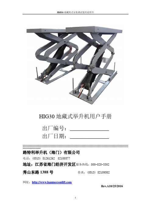
HIG30地藏式举升机用户手册出厂编号:______________出厂日期:____________________________________________________________________________________________________________________________________________________________________________________ ______________________________________________________________________________________________________________________________________________________________________ ____________________________路特利举升机(海门)有限公司电话:(0513) 81261262 82100577地址:江苏省海门经济开发区服务热线:800-828-3302秀山东路1388号传真:(0513) 82109502网址:Rev.A10/25/2016特别说明☐装运过程中造成设备的损坏,须由购买者向承运单位索赔。
☐设计和制造时已经考虑到安全性能。
然而,适当的培训和周密地操作也能增加安全性。
未阅读该说明书,不得操作或修理该设备。
☐查明电机铭牌上电源、电流状态等要求,须由专业合格的电工接电。
☐本公司对产品的局部结构改进恕不通知。
对先前销售产品的更新没有任何义务。
☐请仔细阅读和填写本说明书的末页《保修卡》,反馈给经销商和本公司备案。
作为提供售后服务的依据之一。
否则视为自动放弃享受相应服务的权利,责任自负。
☐不得提升超过设备额定提升重量3吨负荷。
每一个跑道载荷不得超过1.5吨☐认真阅读设备上的警示标志。
目录第一章概述 (4)第二章举升机保养与检查须知 (5)第三章举升机操作注意 (6)第四章产品结构及原理……………………………………………………7~9第五章安装调试工具与开箱 (10)第六章设备的安装..................................................................10~14 第七章设备的调试.....................................................................15~16 第八章操作说明........................................................................17~18 第九章常见问题及解答 (19)第十章储存与报废 (20)第十一章零部件分解图……………………………………………………21~26第十二章产品保修卡…………………………………………………………27~30第一章概述1.1用途本机适用于总重量3吨及以下的各种小型车辆的举升、进行车辆的检修、维护保养或清洗作业。
MC30E6080 用户手册说明书
SinoMCU 8位集成控制芯片MC30E6080用户手册V1.1本产品为广东晟矽微电子有限公司研制并销售,公司保留对产品在可靠性、功能和设计方面的改进作进一步目录1产品概要 (3)1.1产品特性 (3)1.2订购信息 (4)1.3引脚排列 (4)1.4端口说明 (5)2合封EEPROM (6)3封装尺寸 (7)3.1SOP14 (7)3.2SOP8 (7)4修订记录 (8)1产品概要1.1产品特性⏹8位CPU内核✧精简指令集,5级深度硬件堆栈✧CPU为单时钟,仅在系统主时钟下运行✧系统主时钟下F CPU可配置为2/4分频⏹程序存储器✧1K×14位OTP型程序存储器(烧录1次)✧0.5K×14位OTP型程序存储器(烧录2次)⏹数据存储器✧49字节SRAM/REG型通用数据存储器,支持直接寻址、间接寻址等多种寻址方式⏹2组共12个I/O✧P0(P00~P03),P1(P10~P17)✧P13可配置为单输入口或输入/开漏输出口,可复用为外部复位RST输入,编程时为高压VPP输入✧P15/P14可复用为外部时钟振荡器输入/输出✧P0可配置为内置上拉或下拉电阻,P10~P17内置上拉电阻,P10~P12内置下拉电阻,均可单独使能✧P10~P12/P14~P17可选开漏或推挽输出✧P0可配置为单输出口或输入/推挽输出口,为输入/输出口时可配置使能键盘中断唤醒功能✧P1所有端口均支持键盘中断唤醒功能,并可单独使能⏹系统时钟源✧内置高频RC振荡器(16MHz/8MHz/4MHz/2MHz/1MHz/455KHz),可用作系统主时钟源✧内置低频RC振荡器(32KHz),可用作系统主时钟源✧支持外接高频晶体振荡器(455KHz/1MHz~16MHz),可用作系统主时钟源✧支持外接RC振荡器(0~4MHz),可用作系统主时钟源✧支持外接低频晶体振荡器(32768Hz),可用作系统主时钟源、或定时器RTC时钟源⏹系统工作模式✧运行模式:CPU在系统主时钟下运行✧休眠模式:CPU停止运行,系统主时钟源停止工作⏹内部自振式看门狗计数器(WDT)✧与定时器T0共用预分频器✧溢出时间可配置:4.5ms/18ms/72ms/288ms(无预分频)✧工作模式可配置:开启WDT、关闭WDT,也可软件控制开启或关闭⏹2个定时器✧8位定时器T0,支持外部RTC时钟,可实现外部计数功能,与WDT共用预分频器✧8位定时器T1,可实现外部计数、BUZ、3路共周期独立占空比的PWM(可组合成1对带死区的互补PWM)⏹中断✧外部中断(INT),键盘中断(P00~P07,P10~P17),定时器中断(T0~T1)⏹ 低电压复位LVR✧ 1.8V/2.0V/2.2V/2.4V/2.5V/2.6V/2.7V/2.8V/3.0V/3.2V/3.6V/3.8V ⏹ 低电压检测LVD✧ 1.8V/2.0V/2.1V/2.2V/2.4V/2.5V/2.6V/2.7V/2.8V/3.0V/3.2V/3.3V/3.6V/4.0V/4.2V ✧ 可选择LVDI 输入电压与内部1.08V 比较⏹ 内部合封EEPROM 器件(24C02,器件地址编码为000H ) ⏹ 工作电压✧ V LVR30 ~ 5.5V @ Fcpu = 0~8MHz ✧ V LVR27 ~ 5.5V @ Fcpu = 0~4MHz ✧ V LVR20 ~ 5.5V @ Fcpu = 0~2MHz ✧ V LVR18 ~ 5.5V @ Fcpu = 0~32KHz/2 ⏹ 封装形式✧ SOP14/SOP81.2 订购信息产品名称 封装形式 备注 MC30E6080A0J SOP14 MC30E6080A0HSOP81.3 引脚排列MC30E6080A0JEE_VDD/VDD P00EE_SDA/P17EE_SCL/P16[SDO]/OSCO/P14[VPP]/RST/LVDI/P13GND/EE_GNDP02P03P01P10/INT/TC1/PWM2/[SDO]P11/PWM1/[SDI]P12/TC0/BUZ/PWM0/[SCK]MC30E6080A0JSOP141234567814131211109ERCI/OSCI/P15MC30E6080A0HMC30E6080A0HSOP812348765EE_VDD/VDD [SDO]/OSCO/P14[VPP]/RST/LVDI/P13GND/EE_GNDP10/INT/TC1/PWM2/[SDO]P11/PWM1/[SDI]P12/TC0/BUZ/PWM0/[SCK]P17:EE_SDA P00:EE_SCLERCI/OSCI/P151.4 端口说明端口名称(MCU )类型 功能说明VDD P 电源 GND P 地P00~P03 D GPIO (可配置为单输出口或输入/推挽输出口) 可配置为内部上拉或内部下拉P10~P12 D GPIO (可选推挽/开漏输出),内部上/下拉 P14~P17 D GPIO (可选推挽/开漏输出),内部上拉 P13 D GPIO (可配置为单输入口或输入/开漏输出口) 内部上拉 INT DI 外部中断输入TC0~TC1 DI 定时器T0~T1的外部计数输入 PWM0~PWM2DO 定时器T1的3路PWM 输出 BUZ DO 定时器T1的BUZ 输出 LVDI AI LVD 外部电压输入 OSCI ,OSCOA 外部时钟振荡器输入/输出 ERCI AI 外部RC 振荡器输入 RST DI 外部复位输入SCK ,SDI ,SDOD 编程时钟/数据输入/数据输出接口 VPPP 编程高压输入端口名称(EEPROM )类型 功能说明 EE_VDD P EEPROM 电源 EE_GND P EEPROM 地 EE_SCL DI EEPROM 时钟接口 EE_SDADEEPROM 数据接口 注:P-电源;D-数字输入输出,DI-数字输入,DO-数字输出;A-模拟输入输出,AI-模拟输入,AO-模拟输出。
HyPMHD30集成手册中文版
30 KW 氢燃料电池发电模块HyPM® HD 30集成操作手册第4版此产品受6,436,563, 6,866,061, 6,878,477, 7,018,732, 7,077,187, 7,148,654美国专利及其它申请中的专利保护。
30 kW氢燃料电池发电系统HyPM® HD 30集成操作手册第4版保留所有版权。
未经Hydrogenics公司书面授权,手册的任何一部分均不得以任何方式或任何手段(电子的、机械的)复制或传播。
2013年8月印制修订历史担保和责任1 概述2 安全3 产品概述HyPM® HD 30属于长寿命/移动电源系列。
经过设计、优化,它可以应用在多种移动领域。
除了HyPM燃料电池电堆以外,产品还包含了燃料、氧化剂及水的管理,以及气体净化处理辅助部件,集成了软件控制及电源调节。
HyPM结构最显著的特点如下:✓随负荷变化,相应快速✓无限制启动次数,不会对电堆产生负面影响✓内置先进的诊断✓燃料利用率高✓液体冷却,能够有效的带走系统或沟槽内的热量,以应用在其它地方✓低压操作✓安静3.1 技术规格表3-1FCPM技术规格1.大约是底座外围尺寸,不包括空气供应系统和水泵。
2.冷藏处理后产品质量在湿基准基础上有上下1 kg浮动。
产品质量不包含空气供应系统和水泵。
3.产品尺寸以最外围为基准,不包含接插件和法拉。
4.禁止用户超功率使用。
最大输出电流禁止使发电系统超过额定功率。
模块额定功率是在最初工程测试验收时确定的,工况条件为环境温度为21℃,海拔高度为200 m,燃料和氧化剂温度均为21℃。
FCPM须按照说明书规定运行。
否则,会影响电堆性能包括电堆耐久性,毁坏电堆。
5.输出电流由用户决定,但禁止超过由CAN总线输出的“允许消耗电流”。
FCPM禁止在低于15 A下运行5min。
6.平均最高效率在模块出厂验收测试得到,约有±3 %的误差。
工况条件为环境温度为21℃,海拔高度为200 m,燃料和氧化剂温度均为21℃,操作电流约为100 A dc(以氢气低热值为准,25℃,101.3 kPa)。
电子客户端产品说明 - 30英寸双向熔炼自由摆放烹饪器说明书

30"DUAL-FUEL FREESTANDING RANGE MODELS:KFDC500JSS01(Stainless)Illus.No.Part No.Description1Literature PartsW11114331Guide,Use And CareW11114334Instructions,InstallationW11184759Guide,InternetConnectivityW11202391Diagram,Wiring(Cooktop)W11202385Diagram,Wiring(Oven)W11202289Sheet,TechW11114332Guide,Quick Start Illus.No.Part No.Description2W10892994Assembly,ValveManifold(Left Front,Left Rear)W10892997Assembly,ValveManifold(Right Front,RightRear)3W10903728Switch,Harness4W11121194Bracket,Manifold5W11121317Module,Spark64453116Adapter,Male77101P426-60Screw8W10892281Tube,Manifold Supply(Left)W10892292Tube,Manifold Supply(Right)9Box,Burner(NotServiced)Illus.No.Part No.Description10W10115843Cover,Ignition11W11121361Filler,CooktopFOLLOWING PARTSNOT ILLUSTRATEDW11200301Harness,Main(30")W11200328Harness,CooktopW10780278Harness,Door LockW11200325Harness,CommunicationW11242785Harness,WIFIW11212216Cord,Power9759877Retainer,Strain ReliefW10253333Bracket,Anti-Tip7101P485-60Screw,Anti-Tip KitW11238042Kit,LP ConversionIllus.No.Part No.Description1W11106881Panel,Cabinet Side(Left)W11106880Panel,Cabinet Side(Right)2W10892774Assembly,OrificeHolder(Left Front)W10892484Assembly,OrificeHolder(Left Rear)W10892479Assembly,OrificeHolder(Right Front)W10892735Assembly,OrificeHolder(Right Rear)3W10892422Orifice,Main(17.4K)(Left Front,RightFront)W10892419Orifice,Main(15K)(Left Rear)W10892435Orifice,Simmer(2.6K)(Left Front,RightFront)W10892438Orifice,Simmer(5K)(Right Rear)4W11238757Igniter(Left Front,RightFront)W10892340Igniter(Left Rear)W11114379Igniter(Right Rear)Illus.No.Part No.Description5W11291183Burner,Grate(WithWok Ring)6W11291179Burner,Grate7W11323261Screw(8-18X1")W11323309Screw(8-18X1/2")8W11281269Barrier,ApplianceManager9W11436334Interface,User10W11205795Cover,WIFI Outer11W10883433Bezel(Rear Burners)12W10881642Bezel(Front Burners)13Cap,BurnerW11121389Black(Set Of4)14W10891746Spreader,Flame(High)(Left Front,RightFront)W10891974Spreader,Flame(Low)(Left Rear)W10891978Spreader,Flame(AUX)(Right Rear)15W11036559Spring Clip,Range16Knob,Oven ModeW11249667Stainless17W11100279Manager,Appliance(Powermax)18Panel,CooktopW11038235Black(Left)W11038245Black(Right)Illus.No.Part No.Description19W11130078Antenna,WIFI20W10568405Assembly,Speaker21W10130760Bracket,MovingConsole(Left)W10130759Bracket,MovingConsole(Right)22W11328357Screw23W10877949Panel,Console24Knob,SingleW10912166Stainless25Knob,DualW10883172Stainless26W10896366Assembly,Light Pipe27Bezel,OvenW10913810Stainless28Knob,OvenTemperatureW11429269Stainless29W11205794Cover,WIFI Inner30W11241511Button Assembly,Oven Light31W11156414Trim,Island32Trim,T-StripW10271524Black337101P426-60Screw34W11241510Button Assembly,Oven Start353400814Screw36W11291178Kit,Grate Filler37W11042504Bumper,Grate38W11110768Assembly,WIFIModule397101P624-60ScrewIllus.No.Part No.Description1W11394773Kickplate2W11324989Back,Chassis3W10138054Assembly,Roller4W11109583Duct,Bottom(30")57101P426-60Screw69760860Leveler7W10908710Base,Leveling Leg84449743Screw9W11369237Cabinet,ApplianceManager10W10115869Shaft,Long Illus.No.Part No.Description11W10115793Shaft,Short12489504E-Ring13W11106963Tube,PressureRegulator14W11087491Support,Channel15W11115328Gasket,Oven(30")16W11050145Duct-Chassis,Rear17W11368831Channel,Wire18W11362015Retainer,Gasket(9"Long)19W11324986Top,Chassis20W11040802Chassis,BottomIllus.No.Part No.Description21W11103334Panel,Back Top22W11034134Panel,Back Bottom23W11096823Bracket,PressureRegulator24W10449140Regulator,Pressure25W11036559Spring Clip,Range26W11106341Drawer,ApplianceManager27W11199181Cover,Foot(Left)W11199178Cover,Foot(Right)28W10919715GasketIllus.No.Part No.Description14449751Thermostat(TOD)2W10622170Probe,Sensor3W10351278Bumper&Screw4W10830016Latch,Motorized5W11290663Tube,Vent6W10169756Lens,Light7W11223932Assembly,Oven Light8W10169757Bulb,Light9W11096294Receiver,Hinge(Left)Illus.No.Part No.Description10W11096293Receiver,Hinge(Right)11Liner,Oven(NotServiced)12W11102297Chassis,Side(Left)W11102296Chassis,Side(Right)137101P426-60Screw14W10160858Cover,LatchIllus.No.Part No.Description153196176Screw16W11192755Frame,FrontFOLLOWING PARTSNOT ILLUSTRATEDW10282810Insulation,Wrap,30"W10282818Insulation,Back,30"3400968NutVENTING PARTSVENTING PARTSIllus.No.Part No.Description1W10818234Slope,Exhaust Vent(30")2W11105223Vent,Cooling Top(30")3W11200129Blower4W11105222Vent,Cooling Bottom(30")Illus.No.Part No.Description5W11109518Plate,Cooling Latch6W11353392Box,Terminal77101P426-60Screw8W11047754Bracket,Blower Mount9W10270397Seal,Vent Slope(30")Illus.No.Part No.Description10W10270396Seal,Chimney119761958Block,Terminal12112432Nut,Hex13W11106956Cover,ChannelIllus.No.Part No.Description1W11036771Liner,Door2W11413190Insulation,Door(30")3W11184409Glass,Inner4W11194821Retainer,Glass5W11390105Hinge,Door(Left)6W11390124Hinge,Dual(Right)Illus.No.Part No.Description7W10272594Frame,Glass8W10898280Screw9W10656499Screw10W11389280Assembly,Outer Door(Includes Handle)11W11362707Handle Assembly,DoorIllus.No.Part No.Description12W11197830Bracket,Handle13W10518672Badge14W10276043Screw15W11361073Medallion,Handle16W10162096Screw17W10607120ScrewIllus.No.Part No.Description1W10115994Element,Broil2W10282821Insulation,ConvectionCover3W10570887Rack,Oven4W11108461Rack,Oven(Sliding)5W10160856Shield,Element Broil6W11212180Baffle,Convection7W10722667Fan,Convection8W10631503Blade,Fan Illus.No.Part No.Description9W10261523Plate,Fan10W10631504Nut,Acorn(LH)119762242Element,ConvectionSteam12W11109421Tray,Hidden Bake139755542Probe,Temperature144449154Screw159755543Jack,Meat Probe16W11033111Nut,LockingIllus.No.Part No.Description17W10739592Screw18W10115995Element,Hidden Bake19W10720084ScrewOPTIONAL PARTS(NOT INCLUDED) Illus.No.Part No.DescriptionACCESSORY PARTS4396920Stainless SteelCleaner&PolishW10160195Cover,Grill/GriddleW10216179Ring,WokBacksplashW1028544948"With Shelves31464Cleaner,CooktopW10123240Rack,Broiler Pan&Roasting8284755Backsplash(Adjustable)JXA9001CDPStainless SteelWallsplashW11238043Kit,High AltitudeMedallion,HandleW11368841SI.SilverW11368841BO.Black ANOW11368841RE.Red ANOW11368841MP.Marscapone(Cream)W11368841NE.New GoldW11368841CF.CopperW11368841BN.BronzeW11368841DD.Dark Blue。
MHDD中文手册
MHDD中文手册MHDD专业底层硬盘诊断工具软件.使用MHDD 指令,从最简单的到最危险的:设备识别指令ID, [F2], EID, shift[F2], shift[F3]SMART 属性F8SMART ERLOGSMART DATASMART TESTSMART AAS Auto Attribute save扫描(Scanning)磁盘MAKELOG or SCAN F4如果发现有UNC怎么办噪音(Acoustic)管理AMM加密(Security)指令PWD, LOCK, UNLOCK, DisablePassword 擦除(Erase)ERASE读取主机保护区域(Host Protected Area)显示HPA硬盘的原始(出厂)容量RHPA减小硬盘容量HPA恢复原始容量NHPA.将扇区写到文件, ATOF自动分割文件(Atomatically Splitting file)。
从文件写到磁盘FF ,设备配置CONFIG批处理F5其它MHDD 指令SWITCHMBR, CLRMBR.命令行开关/NOPINGPONG, /DISABLEBIOS, /DISABLESCSI, /ENABLEPRIMARY和/ROCFG 文件常见问题(FAQ)关于MHDD 项目MHDD 是一个体积小但是功能强大的免费底层磁盘工具。
它的第一个版本于2000年发布,作者Dmitry Postrigan 的目标是开发一个著名的权威的硬盘诊断工具。
MHDD 第一个版本可以在CHS (Cylindar, Head,Sector)模式下对IDE硬盘进行表面扫描。
MHDD 现在可以访问扇区,查看S.M.A.R.T. (SMART) 和其它磁盘参数,例如:噪声管理,安全机制,主机保护区域等。
用户可以使用简单的脚本执行一序列的指令。
本文原始链接::/docs/knowledge/94-mhdd-chn-manual.html英文原始链接:/docs/MHDD_en_manual.html如何工作在DOS 下如果要从磁盘读取扇区,需要通过BIOS 来执行。
Powermax30 AIR 专业级气吹式平板系统说明书
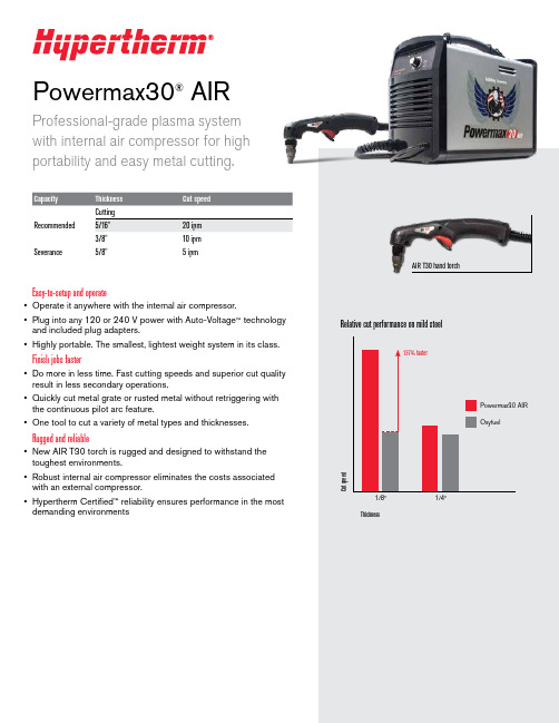
Powermax30®AIRProfessional-grade plasma system with internal air compressor for highportability and easy metal cutting.Recommended Severance5/8"5 ipmEasy-to-setup and operate• Operate it anywhere with the internal air compressor.• Plug into any 120 or 240 V power with Auto-Voltage ™ technology and included plug adapters.• Highly portable. The smallest, lightest weight system in its class.Finish jobs faster• Do more in less time. Fast cutting speeds and superior cut quality result in less secondary operations.• Quickly cut metal grate or rusted metal without retriggering with the continuous pilot arc feature.• One tool to cut a variety of metal types and thicknesses.Rugged and reliable• New AIR T30 torch is rugged and designed to withstand the toughest environments.• Robust internal air compressor eliminates the costs associated with an external compressor.• Hypertherm Certified ™ reliability ensures performance in the mostdemanding environmentsAIR T30 hand torchMoisture removal systemCompressorSystem includes• Power supply, AIR T30 hand torch with 15' lead and work clamp with 15' lead• 240 V/20 A plug with adapters for 120 V/15 A and 240 V/20 A circuits• Operator and safety manuals • 1 nozzle and 1 electrode •Carrying strapTorch consumable partsHigh performing technologyThe new patent-pending consumable designs enable consistent cutting by optimizing the air flow from the compact, internal compressor. Coupled with the highly effective moisture removal system, the Powermax30 AIR provides great cut quality and performance in hot and humid conditions.Customer testimonial“Because our company provides service in very remote places where the access for air compressors is very limited, the portability of the Powermax30 AIR with the internal compressor, makes it ideal for field services. It also eliminates the need for oxyfuel cutting, consequently reducing the cost and increasing the productivity of the cutting process.”Diego Nunes Fernando, BNG Metalmecânica, BrazilCommon applicationsHVAC, property/plant maintenance, fire and rescue, general fabrication, plus:ConstructionVehicle repair and modificationAgriculturalRecommended Hypertherm genuine accessoriesFace shieldClear face shield with flip-up shade for cutting and grinding. Safety shield included. ANSI Z87.1, CSA Z94.3, CE 127239 Face shield shade 6127103 Face shield shade 8Flip-up eyeshadesShade 5 (for <40 A) flip-up shade, anti-scratch lens and adjustable frame. ANSI Z87.1, CSA Z94.3, CE.017033 Flip-up eyeshadesHyamp ™ cutting and gouging glovesInsulated for heavy duty applications. Gun-cut palm design with seamless trigger finger and extended cuff provide flexibility and protection.017025 Medium 017026 Large 017027 X-large 017028 2X-largeSystem dust coversMade from a flame-retardant vinyl, a dust cover will protect your Powermax ® system for years. Made in USA.127469 Cover, Powermax30 AIRCircle cutting guidesQuick and easy set up for accurate circles up to 28" diameter. For optional use as a stand-off guide for straight and bevel cuts. Made in USA.127102 Basic kit – 15" arm, wheels and pivot pin027668 Deluxe kit – 11" arm, wheels, pivot pin, anchor base and plastic casePocket level and tape holderMagnetic base and tape holder with built-in level. Made in USA.017044Pocket level and tape holderEnvironmental stewardship is a core value of Hypertherm. Our Powermax products areengineered to meet and exceed global environmental regulations including the RoHS directive.Engineered and assembled in the USA ISO 9001:2008Hypertherm, Powermax, Auto-Voltage, Hypertherm Certified, and Hyamp aretrademarks of Hypertherm Inc. and may be registered in the United States and/or other countries. All other trademarks are the properties of their respective owners.©12/2014 Hypertherm Inc. Revision 0860620。
配网自动化产品手册说明书

通合电子科技股份有限公司TD配网自动化产品手册DISTRIBUTION NETWORK ANTOMA TION PRODUCT MANUAL秉承创业精神 专注电力电子高效利用能源 服务全球用户电话传真邮编/Pos:050035地址/Add:石家庄高新区漓江道350号No.350 Lijiang Road,Shijiazhuang,China石家庄通合电子科技股份有限公司SHIJIAZHUANG TONHE ELECTRONICS TECHNOLOGIES CO.,L TD秉承创业精神,专注电力电子高效利用能源,服务全球用户ADHERING TO THE SPIRIT OF ENTERPRENEURSHIP, FOCUS ON POWER ELECTORONICS;SUFFICIENT USE OF ENERGY,SERVING GLOBAL USERS.通合科技以“秉承创业精神、专注电力电子、高效利用能源、服务全球用户”为企业使命,秉承“贡献、共益、感念、高效、创新”的核心价值理念,致力于电力电子行业技术创新、产品创新、管理创新,为客户提供系统解决方案,引领行业发展。
公司简介 (01)发展历程 (03)研发实力 (05)测试中心 (07)制造中心 (08)TH27D11Z-220AC电源模块 (09)THF300B2424-S电源模块 (11)THF300C24-S电源模块 (13)THD500B48-S电源模块 (15)THD500B4824-S电源模块 (17)THD1000B4824Z-A电源模块 (19)石家庄通合电子科技股份有限公司SHIJIAZHUANG TONHE ELECTRONICS TECHNOLOGIES CO.,LTD CONTENTS目录ABOUT TONHE关于通合石家庄通合电子科技股份有限公司是一家致力于电力电子行业技术创新、产品创新、管理创新,以高频开关电源及相关电子产品研发、生产、销售、运营和服务于一体,为客户提供系统能源解决方案的高新技术企业。
SI-30 chinese manual

! 注意!!!
本中文操作说明书是由英文原版翻译而成,仅供用户参考,详情请参 阅随机英文原版说明书;
因生产商对设备更改而使说明书与实际操作造成的差异,恕不另行通 知。
பைடு நூலகம்广州市一帆船务设备有限公司
2
自动识别系统 SI-30 中文操作说明书
目
录
1. 缩写.....................................................................................................................................5 2. 概要.....................................................................................................................................5
2.1.1. 主要信息 ........................................................................................
PHM30简体中文说明书

PHM-30精密微束等离子焊机产品使用手册北京三力易胜·Beijing TONKS目录1.介绍 (2)1.01注意、小心、警告 (2)1.02 重要的安全预防措施 (2)2、一般信息 (4)2.01 本说明书 (4)2.02 PHM-30逆变式等离子焊机描述 (4)2.03 PHM-30电源技术数据 (4)2.04 PHM-30系统 (5)2.05 组成系统的要求 (5)2.06 等离子焊接介绍 (5)2.07 操作原理 (5)3、安装 (6)3.01 安装环境 (6)3.02 开箱 (6)3.03 系统连接示意图 (7)3.04 输入电源的连接 (9)3.05 工件电缆连接 (9)3.06 离子气与保护气的连接 (9)3.07 焊枪连接 (10)3.08 遥控连接 (10)3.09 循环冷却 (10)4、操作 (11)4.01 引言 (11)4.02 焊机面板说明 (11)4.03操作过程 (13)5、日常保养 (15)5.1 引言 (15)5.02 日常保养 (15)5.03 基本故障预防 (15)6、系统的完整性 (18)1.介绍1.01注意、小心、警告通过本说明书,你可以认识到:“注意”、“小心”、“警告”被认作为是最重要的信息部分,这些部分的区别如下:▲注意特别需要强调的一种操作过程或背景信息,或者有助于系统的有效操作。
▲小心一种程序,如果操作不当,可能会损坏设备。
▲警告一种程序,如果操作不当,在操作区内可能会危及操作者或者他人。
1.02 重要的安全预防措施▲警告操作和维修等离子弧设备,可能造成危险并影响你的健康。
为了防止可能的伤害,在使用本设备前必须认真阅读、理解下列所有的警告、安全预防与指示。
如果您有任何问题时可拨打电话86-10-81454970或与所在地分销商联系。
◆气体与烟雾✓在等离子焊接过程中产生的气体和烟雾会对您的健康造成危害。
✓在呼吸区域中排除所有气体与烟雾,保证您的头部排除焊接烟雾。
冰淇淋机HD22和HD30产品手册说明书
Product Manual for Ice Dispensers Models HD22and HD30HD22and HD30IntroductionTo the owner or user:This product manual is asource of information about the installation,startup,cleaning,maintenance and repair of theproduct.Table of Contents Introduction·················································Page1 General Description·············································Page2 Specifications&Limitations·········································Page3HD30Dimensioned Illustration·······································Page4HD22Dimensioned Illustration·······································Page5 Product Description·············································Page6 Unpacking··················································Page7 Installation-Plumbing···········································Page8 Installation-Electrical and Ice Machine Assembly·····························Page9 Final Check List/Initial Start Up·······································Page10 Use·····················································Page11 General Care and Cleaning·········································Page12 General Care And Cleaning-Continued··································Page13 Maintenance················································Page14 Adjustments·················································Page15 Service Diagnosis··············································Page16General DescriptionThe HD22is a hotel/motel ice dispenser.It is designed to use a Scotsman C0322or C0522cube ice machine as the source for ice.The HD30is a wider version of the HD22and is designed to use a Scotsman C0330or C0530cuber as its source of ice.Additional models may be used,see sales information for details.Flaked or nugget ice is not recommended for use in these dispensers.Ice from the cuber falls into the insulated hopper,where it is stored until needed.When a user pushes the dispense chute a rotating wheel scoops the ice up to the top front of the hopper where there is an outlet to the ice chute.HD22and HD30ModelDimensions w”x h”x d”with 6”leg Basic Electrical volts/hertz/phaseModel DescriptionBin StorageCapacity,ARI ratedHD22B-1A 22x 53x 33½115/60/1Basic 22”model,60Hz 120lb HD22B-6A 22x 53x 33½230/50/1Basic 22”model,50Hz 120lb HD30B-1A 30x 53x 33½115/60/1Basic 22”model,60Hz 180lb HD30W-1A 30x 53x 33½115/60/1Water station model180lbHD30B-6A30x 53x 33½230/50/1Basic 30”model,50Hz 180lbAll 60Hz models are supplied with an 11’power cord,50Hz models have a 1.1meter power cord.Basic models dispense ice when their chute is pushed.Coin/token models discontinued in 2011.Cuber Model Fits Dispenser Adapter C0322HD22None Needed C0522or CB0522HD22None Needed C0330or CB0330HD30None Needed C0530or CB0530HD30None Needed*Higher capacity cubers,C0630or C0830,may also be used,but they require 230volt power.Basic SpecificationsSpecifications&LimitationsThis dispenser is designed to be installed and operated indoors,in a controlled environment.Its minimum and maximum operating temperature limits are the same as those for the ice machine.Minimum MaximumAir Temp50o F.100o F.Voltage60Hz104126Check the nameplate,located on the back of the cabinet for specific information.Scotsman reserves the right to make design changes and/or improvements at any time. Specifications and designs are subject to change without notice.Scotsman assumes no liability or responsibility of any kind for products manufactured by Scotsman that have been altered in any way,including the use of any parts and/or other components not specifically approved by Scotsman.ModelsThere are twp versions of the HD30dispensers: Basic and Water Station.The Basic version is constructed to deliver ice when the ice chute is pushed in,and it continues to vend ice as long as the ice chute is held in.The Water Station version is a Basic version with a mechanical water faucet added to the left of the ice chute.Water is dispensed whenever the faucet lever is pushed back.The HD30is available in all versions,the HD22is only available as a Basic model.50Hz.The Basic models of the HD22and HD30are available in230volt50Hz electrical for those countries with that type of electrical service.HD22and HD30HD30Dimensioned IllustrationHD22and HD3030"762.428"711.210"WATER VALVE HEIGHT (WATER FILLER ONLY)254.86"152.453 1/4"1351.3ICE FILL STATION 8 3/4 [221.5] HIEGHT 13 1/2 [342.9] WIDTH 8 1/2 [215.9] DEPTHRIGHT SIDEFRONT24"609.681 1/4"2062.525 5/8"650.533 1/2"849.4ICE HEADICE HEADBACKPOWER CORD17 3/4"451.11"24.17 1/2"189.47"179.17 1/2"189.717 1/2"444.4WATER INLET 3/8 FLARE (WATER FILLER ONLY)3/4 FPT DRAIN(2) 5/16-18 UNC ICE HEAD MOUNTINGNote:Ice fill station depth is curved to match large ice buckets.Listed number is the maximum depth.HD22Dimensioned IllustrationHD22and HD3028"711.20022"558.86"152.453 1/4"1351.3ICE FILL STATION 8 3/4 [221.5] HIEGHT 13 1/2 [342.9] WIDTH 8 1/2 [215.9] DEPTH24"609.681 1/4"2062.533 1/2"850.125 5/8"650.6ICE HEADICE HEADFRONTRIGHT SIDE16"406.41"24.13 1/2"88.97"179.1POWER CORD3/4 FPT DRAIN BACK(2) 5/16-18 UNC ICE HEAD MOUNTINGNote:Ice fill station depth is curved to match large ice buckets.Listed number is the maximum depth.Product DescriptionAll models consist of a plastic lined,insulated hopper mounted to a metal base.The hopper contains a 15blade plastic dispense wheel and a stainless steel sweep arm.The top front of the hopper has a removable door to facilitatemaintenance and cleaning of the hopper without removal of the ice machine.The dispense wheel and sweep arm rotate when the dispense drive motor is actuated.The drive motors actuation is controlled by the agitation timer or the vend switch.When the ice dispense chute is pushed back it moves the actuation lever up.The actuation lever releases the chute door and pushes the vend switch arm up.Whenswitch arm has moved a preset switch contacts close,providing power dispense drive motor.Ice is delivered to end of the ice chute by the dispense slides down the chute to the container The container rests on a grill,the grills openings are over the ice catch pan,and any spilled ice goes there.The grill has a flange at the front to help contain the ice if it spills during vending.After the ice dispense chute isreleased,the ice chute door closes to stop ice flow.Ice in the chute willeventually melt.Melted ice water is routed to the drain through ahose attached to the bottom ofthe chute.Spilled ice iscontained in an insulated icecatch pan.Melted ice water from the ice catch pan is routed to the er debris is kept away from the drain in the catch pan by a slotted shield.The side and front exterior panels are made of corrosion resistant metallic finish . The vending area and top panel are made of plastic.HD22and HD30Vend Drive Ice Hose PanUnpackingAfter removing the carton,check for theloose-shipped parts packed in the storage bin.The parts will include a carton with four legs.Remove the leg carton and any other loose-shipped items. To remove the skid,place part of the carton behind the unit and tip the unit on its back.Remove the bolts holding the skid to the base of the HD dispenser and separate the skid from the unit. Install the legs into the base of the unit,using the holes where the skid bolts were.Turn the leg leveler part of the legs in all the way,adjust them later after the unit is in its final installed position. Move the dispenser to an upright position and set it in the location where it will be installed.Note where drain lines and electrical connections will be made.Front Panel RemovalThe front panel rests on the base and is located with pins that stick up from the base.It is retained to the side panels by strikes and latches.The top panel keeps the front panel from moving forward. To remove:1.Disconnect electrical power.2.Remove the two screws holding the top panel to the dispenser.Lift the top panel up and off the dispenser.3.Pull the top edge of the front panel forward until the two snaps disengage.·If the unit is a coin op model,reach behind the front panel and disconnect the coin mechanism harness from the front panel.station model,reach behind shut off the water supply faucet.Then disconnect the shut off valve.up and off the base.HD22and HD30Installation -PlumbingDrain:All models of the dispenser have a 3/4"FPT drain fitting at the bottom of the back panel.Connect 3/4"rigid tubing to this connection,a vent isrecommended for most installations.Route the drain tubing to the building drain.Note:Drain fitting material is plastic.If using copper,sweat the copper tube to copper fitting together before installing on the dispenser.Note:Keep PVC solvent away from all plastic parts of the dispenser.Follow all applicable plumbing codes.Because the drain tubing will be very cold,insulation is recommenced for the tubing.Water:HD30water station models must be connected to a source of potable water.The water supply must have adequate backflow protection to comply with applicable codes.Flush the water supply line before connecting it to the dispenser.HD22and HD30Drain Connection,Back View of DispenserInstallation-Electrical and Ice Machine Assembly The dispenser is supplied with a power cord.Donot use with an extension cord.The unit must beplugged into a properly grounded outlet.The dispenser must be installed so that it is aseparate piece of equipment from the ice machine.The drains and electrical supply must be separate.Follow All Local State and National CodesIce MachineAll models:Place the dispenser in the locationwhere it will be used.Level the top edge of thedispenser front to back and left to right.Sanitize the dispenser bin with a locallyapproved sanitizer.See page13.Place the ice machine on the dispenser and secureit to the dispenser with the hardware and strapsfrom the ice machine.Install it according to theinstructions in the manual included with the icemachine.HD22and HD30Ice MachineDrain,KeepSeparateFloorBack View of HD22Installation Back View of HD30InstallationFasten Ice Machine to DispenserFinal Check List/Initial Start Up1.Check that electrical power has been supplied.2.Check that a drain,separate from the ice machine,insulated and made of rigid tubing,has been connected to the dispenser.3.Check that the ice machine has been properly installed per the ice machines installation directions.4.Check that the ice machine/dispenser assembly is level front to back and left to right.5.Check that optional kits,if any,have been correctly installed.6.Check that the coin box access key,if used,is available.To Start:1.Connect electrical power.The dispensing system will cycle on for a few seconds.2.Go thru ice machine start up procedures.Let ice machine make two harvests.3.Push the ice chute in.4.Dispense wheel turns.5.Ice will be dispensed from ice chute.6.Fill out the warranty registration form and place it in the mail.7.Give the operator any keys and the instructions on the operation and maintenance of the product. Check that the operator knows who to call for service,and has the product/service manuals for the machines.Electrical SequencePushing the ice chute closes a contact to the gear motor.The gearmotor will have power and the dispenser will continue to operate as long as the ice chute is pushed in.This model also has a agitation cycle of 3seconds every6hours.Since the ice chute is not pushed in during agitation no ice is dispensed.HD22and HD30HD22and HD30UseBasic ModelPush the chute back to dispense iceGeneral Care and Cleaning Periodically inspect and clean the ice dispenser to keep it operating at peak performance.Wash the outside of the dispenser with warm water and soap.Rinse off and wipe dry.Cleaning and Sanitizing of the Ice Storage Bin: The minerals,chlorine and other impurities in the water are rejected from the water during the freeze cycle of the ice machine.These minerals will collect in the storage bin.The ice storage bin should be cleaned and sanitized every90days. 1.Remove all of the ice stored inside the dispenser bin and shut off the ice maker.2.Disconnect electrical power to the dispenser.3.Remove top front panel(in front of icemachine).4.Remove the front panel.5.Lift up and remove the access door at the front of the bin6.Reach into the opening,locate the hair pin and pull it out of the shaft7.Pull the sweep arm off the shaft and remove it from the dispenser.8.Pull the dispense wheel off the drive shaft and remove it from the dispenser.9.Mix a solution of5ounces of ice machine cleaner to1gallon of warm(95o F.-1150F.)water. Wash the entire bin area and the delivery area. Use a clean brush or cloth.HD22and HD30Electrical Shockand Moving PartsHazardGeneral Care And Cleaning-Continued10.Rinse all areas washed with clean,fresh water.ing the ice machine cleaning solution,cleanthe ice grill,sink,sweep arm and dispense wheel.Rinse these parts with clean,fresh water.12.To sanitize:Use a locally approved sanitizer.A possible sanitizer:Mix a solution of ice machinesanitizer and water:1ounce of household bleachto2gallons of(95o F.-1150F.)water.Washall interior surfaces,the sweep arm andthe dispense wheel with the sanitizere a clean cloth.13.Allow the parts to air dry.14.Reassemble wheel and sweeparm onto drive shaft.Be sure toreinsert hairpin.15.Replace all panels.16.Reconnect power,be sureice machine is switched back on.HD22and HD30HD22and HD30MaintenanceSpilled ice and user debris will collect in the ice catch pan,located just below the sink grill. Occasionally the debris will need to be removed and the drain flushed out to prevent water back ups.Note:Failure to clean out the ice catch pan will likely result in a water leak,one that is NOT covered by warranty.To clean out the ice1.Remove the front2.Disconnect electrical3.Remove the twothe dispenser.Lift thedispenser.4.Pull the top edge ofthe two snapsIf the unit is a coin opfront panel andharness from the frontIf the unit is a waterthe front panel andto the water faucet.from the shut off valve.5.Lift the front panel6.Pull the ice catchthe drain hose can be7.Pull the drain hose8.Slide the ice catchand clear it of any9.Return the ice catch10.Re-attach the drainIce Catch PanAdjustmentsThe dispenser is preset at the factory.Adjustmentsare rarely needed.Agitation Time Recommendations:The standard time is3seconds on every6hours.Adjust to agitate more frequently if the unit isinstalled in a low temperature environment.However,if the ice being produced by the icemachine is cloudy and crumbles easily,adjust toagitate less frequently.HD22and HD30Agitation Timer,Shown Pre-set to3secondsevery6hours Water Flow Adjustment ScrewService DiagnosisHD22and HD30Symptom Probable Cause Possible FixNo ice is dispensed-Basic Model No power to dispenser Check for proper power,is dispenserplugged in?No ice Check ice machineVend switch does not close Check vend switchCheck chute for proper motionChute cannot be pushed back Check door lock for proper operationInterlock switch open Check interlock switch,be sure toppanel is in placeDrive motor windings open Check drive motorDrive gears failed Check gear reducerNo ice is dispensed-Coin Op Model Same as above plus coin switch doesnot closeCheck coin switchVend timer does not work Connect power to post6of coinmech timer,timer should activate,ready light should be on and pushingthe chute should start the gear motor,if not replace the vend timerOnly dispenses small amount of ice Sweep arm damaged Check/replace sweep armNo water is dispensed-water station model Water shut off Check water supply to unit,checkshut off valve inside cabinetWater leak Drain is plugged Check drain for restrictionIce catch pan has overfilled Remove excess iceIce catch pan screen is plugged Clean screenSeal between ice machine and dispenser is leaking Remove ice machine and replace gasket tapeWater drip from spout Some dripping is normal,but ifsevereCheck spout drain for restrictionCoin operated model“Ready”light is on all the time Resistor is open Replace resistors(15K,2watt inparallel)SCOTSMAN ICE SYSTEMS 775Corporate Woods Parkway,Vernon Hills,IL60061800-726-876217-2957-01。
Marantz Integrated Amplifier MODEL 30 操作说明书
Integrated Amplifier MODEL 30操作说明书附件4安装电池5遥控器的操作范围5部件名称与功能6前面板6后面板9遥控器11连接方法连接扬声器15扬声器连接16连接播放设备17连接录音设备18连接前置放大器或功率放大器19连接带有遥控端子的设备20通过本机上的RC无需视觉接触执行操作20远程连接Marantz音频设备20连接电源线21播放开启电源23切换电源至待机23选择输入源24调节主音量24暂时关闭声音(静音)24调节音调和平衡24播放CD25本机用作功率放大器25录音26设置设置显示屏亮度28设置灯饰LED亮度29设置自动待机模式30设置遥控代码31设置遥控的遥控代码32设置本机的遥控代码32提示提示34故障诊断35电源无法开启/电源关闭36使用遥控器无法执行操作37本机显示屏不显示内容37不发出声音38所需声音没有发出38声音中断或出现噪音39保修和修理40附录术语解释41规格42索引45感谢您选购此Marantz产品。
为确保正确操作,使用该产品前请仔细阅读操作说明书。
阅读之后,请务必妥善保管以备将来参考。
附件请检查并确认本产品附带下列部件。
安装电池1沿箭头所示方向抬起并取下后盖。
2按照指示将两节电池正确插入电池匣内。
3装上后盖。
注0为防止损坏电池或电池漏液 :0请勿将新旧电池混合使用。
0请勿使用两种不同类型的电池。
0如果打算长时间不使用遥控器,请取出遥控器中的电池。
0如果电池漏液,须仔细地擦去电池匣内的漏液,然后装入新电池。
遥控器的操作范围操作遥控器时应将其指向遥控感应窗。
部件名称与功能前面板有关详情,请参阅下一页。
A电源操作(X)键开启/关闭电源(待机)。
(v第23页)B灯饰LED电源开启时此灯点亮。
可以更改亮度和使其熄灭。
(v第29页)C显示屏此键显示各种信息。
D遥控感应窗接收来自遥控器的信号。
(v第5页)E保护电路指示灯保护电路工作时,此指示灯闪烁。
(v第36页)F耳机(PHONES)插口用于连接耳机。
HDRX-30 容性设备绝缘带电测试仪 产品手册说明书
HDRX-30容性设备绝缘带电测试仪产品手册USER’S MANUAL武汉华顶电力设备有限公司Wuhan huading Electric Equipment Co.,Ltd.尊敬的用户,感谢您选用本公司的容性设备绝缘带电测试仪。
在正式使用之前,请仔细阅读本说明书,以确保您对本产品安全正确的使用。
如果您对说明书中所述内容有任何疑问或者认为有不妥之处,请您与我公司销售部或者技术部取得联系,我们将竭诚为您服务。
阅读完本说明书后,请妥善保管本说明书,以备后用。
目录1、概述变电站高压电气设备绝缘状况通常有两种监测方式:在线监测和带电(便携)检测。
在线监测方式能够随时获得反映设备绝缘异常的特征参量,便于实现自动化管理,但投资相对较大,安装施工比较麻烦,且需要定期维护;而便携式带电检测方式具有投资少、针对性强、便于安装维护和更新等优点,只要预先在电气设备上安装取样单元,即可通过便携式带电检测仪器,对运行中的电气设备进行定期检测,同样也可达到及时发现绝缘缺陷,延长停电预试周期的目的,可完全替代投资较大的在线监测方式。
容性设备绝缘带电测试仪(以下简称仪器)无论取样单元还是检测仪器,从技术上和使用方便性上都远优于以往的检测系统。
仪器采用全新的设计结构,能够克服现有带电检测系统存在的缺陷,具备多种测试功能,既可对电容型设备进行相对介损测量,还可进行绝对介损测量。
主要用于对运行中的CT、CVT、耦合电容器的电容、介损值和末屏电流等参数进行带电检测,以便确定该设备的绝缘状态。
2、仪器功能及特点2.1采用32位浮点DSP加32位ARM的双CPU方案,确保数据采集速度快、数据测量精度高。
2.2同时具备相对测量功能和绝对测量功能,可根据现场情况灵活选用。
2.3采用高精度外置式穿芯电流传感器,该传感器为穿芯式结构,就近安装于设备附近,末屏引线无断口且引线距离很短,从根本上避免末屏开路等安全隐患;传感器输入阻抗低,可耐受10A工频电流的作用以及10KA雷电流的冲击,满足在线检测的使用条件。
《IDM30E-30EN综合业务传输设备》用户手册
综合业务接入设备用户手册适用于IDM-30E/IDM-30ENV1.0北京瑞光极远数码科技有限公司致用户:⑴感谢阁下使用我公司的产品。
本设备在设计使用范围内具有良好可靠的性能,但仍应避免人为对设备造成的损害或破坏。
请在使用本产品前,仔细阅读本用户手册,并妥善保管,以备参考使用。
⑵安装本产品前请核对型号,并按用户手册要求安装。
⑶请勿让本产品淋雨或受潮,以免损坏。
⑷不要在电源电缆上放任何东西,不要将电缆打结或包住。
为避免引起火灾,应将其放在不易碰到的地方。
⑸电源接头以及其它设备连接件应互相连接牢固,请经常检查。
⑹请注意设备清洁,必要时可用软棉布擦拭。
⑺请注意不要堵塞通风散热孔。
⑻请不要自己修理设备,除手册中有明确指示外。
当设备运行异常时请立即断电并与公司售后服务部联系。
⑼本公司对由合法渠道取得产品的用户提供三个月包换、一年免费质保、终身维护服务。
免费维修服务的有关事项如下:在一年保修期内,如按使用说明书正确使用,并在正常使用情况下发生故障,本公司将负责免费维修;凡将设备自行打开,本公司将不负责维修;超过保修期的设备,我公司仍负责维修,适当收费。
签保修合同按合同处理。
⑽在质保期内由于产品本身质量问题而造成的设备不能正常运行使用,本公司负责更换,回收的产品由本公司所有。
人为对设备造成的损害或破坏,或没有按照本手册操作造成对设备的损伤,我公司概不负责。
版权声明本产品的所有部分,包括本手册及配件等,其产权公司所有。
未经书面许可,不得任意仿制、拷贝、誊抄、转译或以任何形式在网络中传送。
对于以任何形式修改产品造成的产品功能不能实现或对其他产品、人身造成影响,本公司将不负任何责任。
除此之外,本手册所提到的产品规格和技术参数仅供参考,内容亦会随时更新,恕不另行通知,有关信息请向公司查询。
版权所有·不得翻印©北京瑞光极远数码科技有限公司IDM®为北京瑞光极远数码科技有限公司的注册商标。
目录1 产品简介 (1)1.1概述 (1)1.2主要特点 (1)2 设备工作原理 (1)2.1设备示意图 (1)2.2工作原理 (2)3 业务小卡说明 (2)3.1局端电话卡:FXO (2)3.2用户端电话卡:FXS (3)3.310/100M以太网接口卡 (3)4 典型应用 (3)5 接口规范 (4)5.1E1接口规范 (4)5.2FXO/FXS接口规范 (4)5.3以太网接口规范 (4)5.4光接口规范 (4)6 设备安装与维护 (4)6.1设备安装 (4)6.2设备业务开通 (7)6.3设备维护 (7)6.4常见故障排除 (7)1 产品简介1.1 概述IDM-30E/30EN 系列综合业务接入设备是我公司采用大规模集成电路设计的PCM 综合复用设备中的一个系列。
OBackup30AIX版系统管理手册.pdf
OBackup 3.0 AIX版系统管理手册-适用AIX2011年7月免责声明此出版物所有含信息如有更改,恕不另行通知, Inc不对本手册提供任何担保。
对于本手册所含错误以及由于本手册的提供,执行或使用而导致的任何偶然或必然损害赔偿, Inc均不承担任何法律责任。
目录一、概述 (4)1、原理说明 (4)2、版本说明及获取方式 (5)二、OBackup安装 (6)1、安装步骤 (6)2、安装组件 (6)2.1、MasterServer组件安装 (6)2.2、MasterServer 配置 (9)2.3、登录OBackup管理中心 (10)2.4、MediaServer组件安装 (11)2.5、MediaServer配置 (11)2.6、创建存储单元 (13)2.7、BackupAgent组件安装 (17)2.8、BackupAgent配置 (17)三、OBackup配置 (19)3.1、客户端管理 (19)3.1.1、添加主机 (19)3.1.2、管理主机 (19)3.1.3、添加Oracle实例 (20)3.1.4、管理Oracle实例 (20)3.2、作业管理 (20)3.2.1、新建备份作业 (20)3.2.2、管理备份作业 (23)3.2.3、新建恢复作业 (24)3.2.4、作业状态 (25)3.3、介质服务器管理 (25)3.3.1、备份集信息 (25)3.3.2、存储单元 (26)3.3.3、状态 (26)3.4、许可信息 (26)四、联系我们 (26)一、概述OBackup是一个采用异地备份及恢复备份软件, OBackup通过网络将Oracle 生产数据进行在线异地备份及恢复,不占用本地存储空间。
OBackup支持硬盘,磁带存储介质,能够将Oracle备份出来的生产数据直接存储到硬盘或者磁带中,有效的避免了生产数据和备份数据同时损坏的风险。
1、原理说明OBackup 原理说明:BackupAgent:备份客户端,安装到Oracle数据库主机上,实现备份恢复作业。
EGPZ30D资料
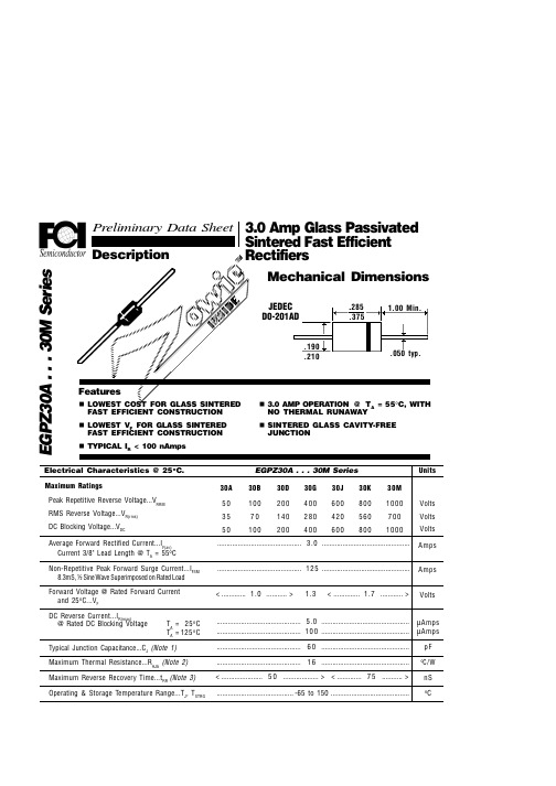
Preliminary Data Sheet 3.0 Amp Glass Passivated Description
Sintered Fast Efficient Rectifiers
JEDEC D0-201AD
.190 .210 .285 .375
EGPZ30A . . . 30M Series
............................................. 3.0 ............................................... ............................................. 1 2 5 ............................................... < ............. 1.0 ........... > 1.3 < .............. 1.7 .. (pF) Typical Reverse Characteristics
Forward Current (A)
Ratings at 25 Deg. C ambient temperature unless otherwise specified. Single Phase Half Wave, 60 HZ Resistive or Inductive Load.
............................................. 5.0 ............................................... ............................................. 1 0 0 ............................................... ............................................. 6 0 ............................................... ............................................. 1 6 ............................................... < ...................... 5 0 ................... > < ............. 7 5 ........... > ......................................... -65 to 150 ..........................................
聚和太阳能30A PWM 充电控制器 (带 LCD 显示屏) 用户手册说明书
PWM Charge Controller with LCD Display30AUser ManualProduct Features1. 12V/ 24 V system voltages are automatically recognized.2. Charging program options for sealed, GEL and flooded lead-acid batteries and lithium batteries are available.3. An upgraded 3-stage PWM charging algorithm is adopted. Application of an equalizing charge to the battery periodically or when over discharged, can effectively prevent the battery from non-equalization and sulfuration, thus extending the battery's service life (with the exception of GEL and lithium batteries).4. With temperature compensation employed, charging parameters can be automatically adjusted (with the exception of lithium batteries).5. A wide range of load working modes facilitate the product's application to different types of street lights and monitoring devices.6. The product provides overcharge, over-discharge, overload protection, as well as short-circuit and reverse-connection protection.7. By virtue of an advanced load starting method, large-capacitance loads can be started smoothly.8. A range of parameter settings and power-down saving functions are available, thus requiring no repeated setting.9. The product provides a dot matrix graphic LCD screen and a human-machine interface with 2 keys.10. The user-friendly design of browser and dynamic interfaces ensures convenient and intuitive operations.11. (An optional communication function) provides a RJ12 data port (output of TTL232 level or blue tooth signals), with the data adopting the standard Modbus protocol, can be used together with our upper computer Monitoring software or mobile phone APP.12. Boasting an industrial grade design, the product can function well in various tough conditions.13. TVS lighting protection is adopted.Panel StructureInstallation Instructions and Precautions1.The controller shall be installed securely, and its dimensions are as follows:External dimensions: 164.0×103.5×47.0 (mm)Installation dimensions: 154×85 (mm)2.Installation hole diameter:3.5(mm)Dimensions in mm3.Precautions:① For a 12 V system, the LCD screen displays "12 V" on the lower-left corner. And it’s similar for 24 V and48 V systems.②The first step is to connect the battery. If the connection is made correctly, the controller screen willlight up; otherwise, check whether the connection is correct.③The second step is to connect the solar panel. If sunlight is present and strong enough (the solarpanel voltage is greater than battery voltage), the sun icon on the LCD screen is on; otherwise, check w hether the connection is correct (it’s recommended that the operation be performed under the debugging mode).the current shall not exceed the cont roller’s rated current.⑤As the controller will generate heat during operation, it's recommended that the controller be installed inan environment with good ventilation conditions.⑥Choose cables with large enough capacity for connection, in case too much loss incurred on the linescauses the controller to misjudge.⑦The controller has a common positive pole inside. If grounding is needed, ground the positive pole.⑧It's important to fully charge the battery regularly. At least once full charging every month isrecommended, and failure to do that may cause permanent damage to the battery. Only when in-flow energy outpaces that out-flow energy can the battery be charged fully, Users shall bear this in mind when confituring the system.⑨Check whether the controller's each connection terminal is tightened securely; if not, it may sufferdamage when the current passes.State IndicatorsLCD Icon Indicated Object State MeaningDay recognition Steady on Day timeNightrecognitionSteady on Night timeSolar panel Steady on Solar panel indicationBOOSTCharging state Steady on Boost chargingFLOAT Steady on Floating charging EQUATIZE Steady on Equalizing chargingBattery Quick flashing Battery overvoltageSlowflashingBattery overvoltageBattery SOC 4 dashes100% 3 dashes 75% 2 dashes 50% 1 dash 25% 0dash 0%LoadSteady on Load turned on Steady on Load turned off Quick flashingOverload or short-circuitprotectionFive Load Working Modes1.Pure light control (0): When sunlight disappears and the light intensity drops to the starting point (light control off), the controller initiates a 10-minute delay (settable) to confirm the starting signal, and then switches on the load for operation. When sunlight emerges and the light intensity reaches the starting point, the controller initiates a 1-minute (fixed) delay to confirm the shutting-down signal, and then shuts down the output to stop the load's operation.2. Light control + time control (1 to 14): The starting process is the same as pure light control. After operating for a preset period of time (settable from 1 to 14 hours), the load stops operation automatically.3. Manual Mode (15): In this mode, the user can switch the loa d on or off by the keys, no matter whether it’s day or night.4. Debugging mode (16):When the solar panel voltage is higher than the “light control off” voltage, switch off the load immediately; when the solar panel voltage is lower than the “light control on” voltage, switch on the load immediately.5. Normal on (17): The energized load keeps in output state.LED Display ModeLEDDisplayMode0 Pure li ght control mode9 Light control + time control (9 hours)1 Light control + timecontrol (1 hour)10Light control + timecontrol (10 hours)2 Light control + timecontrol (2 hours)11Light control + timecontrol (11 hours)3 Light control + timecontrol (3 hours)12Light control + timecontrol (12 hours)4 Light control + timecontrol (4 hours)13Light control + timecontrol (13 hours)5 Light control + timecontrol (5 hours)14Light control + timecontrol (14 hours)6 Light control + timecontrol (6 hours)15 Manual mode7 Light control + timecontrol (7 hours)16 Debugging mode (default)8 Light control + timecontrol (8 hours)17 Normal on modeLoad Working Mode SettingsIn the load mode menu, long press for 2s, and the number (e.g. 15) will begin to flash. Press to adjust the mode (from 0 to 17), and then long press again for 2s to complete and save the setting. Note:1. After parameter adjustment, if is not pressed and held long enough for exiting , the system exits to the main menu after 12s, and the parameter that was set is not saved.2. When the system is saving data, the screen may shake slightly. This is normal and the user may ignore it.Safety Advice1) When connected to a 24 V or 48V system, the solar panel terminal voltage may exceed the limit for humansafety. If operation is to be performed, be sure to use insulation tools and keep your hands dry2) If the battery is reversely connected, the controller itself won't be damaged, but the load end will have anegative voltage output, which may damage your load device. Take care not to let this happen.3) In a 48 V system, if the battery or solar panel end is reversely connected, the controller is highly likely toget damaged.4) The battery contains a large amount of energy. Therefore, in no cases should the battery be short circuited.It's recommended that a fuse be serially connected to the battery.5) Keep the battery away from fire sparks, as the battery may produce flammable gas.6) Keep children away from the battery and controller.7) Follow the safety advice provided by the battery manufacturer.LCD Screen IllustrationBrowsing Menu on LCD Screen1).Continuously press,the screen will display the following in order: "main menu"---"solar panel voltage"---" solar panel current"---"battery capacity"---"battery voltage"---"discharging current"---"charging amp-hrs"---" discharging amp-hrs"---" temperature inside controller"---" load mode"---" load mode settings"---"error code", and then back to "main menu". If the keys are not operated for 12s, the system will automatically return to display the "main menu"Setting Menu on LCD Screen2). When "load mode" is displayed, long press to enter into the load mode setting Press to adjust the mode, and long press for 2s to save and exit; or else, the system will not save the setting that was just made and automatically exits the setting interface after 12s.Battery Types, Charging Voltages (Lithium Battery), Over-Discharge Return and Over-Discharge Voltage SettingsIn the non-load mode menu:1) When is long pressed, the first interface entered is for battery type setting, and the flashing one is the battery type currently selected. Press to selet among FLD/GEL/SLD/LI.2) After selection, short press to enter into over-discharge return and over-discharge voltage settings; or the first to enter charging voltage setting menu for lithium battery.3) After parameters have been set, long press for 2s to save and exit.Parameters shall be set according to the following rule: over-discharge voltage < over-discharge return voltage <= under-voltage warning < float charging voltage < boost charging return <= equalizing charging voltage <overcharge voltage; and two adjacent values shall have a difference greater than 0.5V.Charging and Discharging Overload Pretection and Recovery TimeIn the charging and discharging overload protection mechanism, the relation between overload current and protection time is as follows: An overload current 1.25 times of the rated current initiates a delay of 30s before starting protection; similarly, 1.5 times, 5s and 2 times, 1s.Overload recovery: automatic recovery after 1 minute.Load Short Circuit and RecoveryShort-circuit automatic recovery time: 1st time, 5 s; 2nd time, 10 s; 3rd time, 15 s; 4th time, 20 s; 5th time, 4 hours or automatic recovery the next day; or long press to make the load resume output. Communication Port Line Sequence (Only for Controllers with Communication Functions)Controller communication port RJ12 (6-pin)Error Code ListCode on LCD screen Corresponding errorE0 No errorE1 Battery over-dischargingE2 Battery overvoltageE3 Under voltage warningE4 Load short circuitE5 Load overcurrentE6 Controller inner temperature over heatE8 Charging current too highE10 Solar panel input voltage too highCommon Problems and SolutionsSymptoms Causes and SolutionsLCD screen does not light up.Check whether the battery is correctly connected.Incomplete display or no renewal on LCD screen Check whether the ambient temperature is too low and whether the display recovers when the temperature rises.No charging with sunlight present Check whether the solar panel is correctly connected, and contact is good and reliable.Check whether the solar panel voltage falls below the battery voltage.The sun icon does not light up, while the solar panel icon does. The battery voltage is normal, but there is no output. The load will be switched on automatically after 10 minutes (set by the user).The battery icon flashes quickly, and there is no output. System overvoltage. Check whether the battery voltage is too high.The battery icon flashes slowly, and there is no output. The battery is over-discharged, and will recover after recharged adequately.The load icon flashes quickly, and there is no output. The load's power exceeds the rated value or the load is short-circuited. After the problem is solved, long press the key or wait until it recovers automatically.Other symptoms Check whether wiring is sound and reliable, and system voltage is correctly recognized.Technical Data SheetRated current30ASystem voltage Automatic recognition of 12V/24VMax. Solar energy input voltage <55V Max. voltage at thebattery end <34VBattery type ParametersFlooded FLDSealed SLDGEL GELLithium LIDefault SLDOvervoltage protection 16.0V×1/12V ; ×2/24V ; ×4/48V ;Equalizing charging voltage 14.8 14.6 - - Boost chargingvoltage14.6 14.4 14.2 14.4 Floating chargingvoltage13.813.813.8-Charging recoveryvoltage 13.2VOver-discharge recovery voltage 12.5V (settable with the keys ) Over-dischargevoltage 11.0V (settable with the keys ) Equalizing charging interval 30days - -Equalizing charging time 1H-- Boost chargingtime 2H - Temperature compensation -3.0mV/℃/2V-Light control voltage Light control on 5V, light control off 6 V (light control on plus 1V)×1/12V ; ×2/24V ; ×4/48V ; Light control judgment time 10 minutes USB function YesNoNoOperating temperature -25℃to+55℃;IP protection degree IP30 Net weight 390gProtection functions Battery reverse connection protection, solar panel reverse connection protection, reverse charging protection at nightCharging overload protection, overcurrent protection , short circuit protectionDimensions164.0×103.5×47.0(mm)The content of this manual is subjectto change without prior notice.。
Seakeeper 35 30HD 安装手册说明书
INSTALLATION MANUAL*THIS MANUAL ALSO COVERS THE SEAKEEPER 30HD MODEL*Rev 6 JAN 2017INSTALLATION∙Overheadlarge torque about the gimbal axis when the SeakeeperSeakeeper cover panels are provided to prevent personnel from contacting the Seakeeper while it is operation. These coversbe stepped on, or have anything placed top. The coversalways be in place during operation. The cover side panels contain safety shields If it is ever necessary to service the Seakeeper while the flywheel is spinning, the Seakeeper must be locked at the display to stop the Seakeeper from precessing. Seakeeper maintenance should not be attempted unless the Seakeeper is locked and the flywheel has stopped spinning. The Seakeeper should be treated with the same respect one gives a high speed rotating propeller shaft or engine shaft.measured under steady state conditions (no wave load) Seakeeper's lab and test boat. The steady state noise is typically in the range of 70-75dB un-Spreader Bar Lifting Eyes FIGURE 3 – LIFTING ARRANGEMENTFIGURE 4 – EXPLODED VIEW OF INSTALLATION FIXTUREFIGURE 13 – FOAM STRIP INSTALLATIONPlastic ScrewsClean insidesurfaces ofsaddlesFIGURE 14 - SADDLE CLEANINGThoroughly sand all saddle inside surfaces with 80 grit sandpaper. (IMPORTANT BOND STRENGTH MAY BE REDUCED IF THIS STEP IS SKIPPED.)Wipe surfaces clean from dust with alcohol or acetone using new paper towels, not shop MA590 adhesive, apply Plexus PC-120 surfacesurfaces of Seakeeper foundation saddles in accordance with manufacturer instructions. These instructions are located at the end of this section. If using an alternate adhesive,Pneumatic Gunphoto below by attachingnozzle to the end of the mixing tip. Set aside for now as this will be used to inject adhesive into the sides of each saddle after the fixture / saddles are in position.Mixing TipFlexible NozzleInstall provided rubber plugs in 12 holes ofeach saddle. The plugs will limit the adhesivebeing forced out of the injection holes in step6 below.excess adhesive will be needed to make sure all bond gaps are filled.INSTRUCTIONS Product: All Document #: 90213 Process: Plexus PC- 120 Application Instructions Rev.: 1Process Description: Instructions for use of surface conditioner Page 1 of 4What is Plexus PC-120?•Plexus PC-120 is a dual function primer/conditioner designed to clean surface contamination and leave a thin coating of primer on specific metal surfaces.•Although designed specifically for cleaning and priming of Aluminum and Stainless Steel, PC-120 can be used to clean other surfaces in special situations. Contact Plexus Technical Service forrecommendations on any surface other than Aluminum or Stainless Steel.Plexus PC-120 works by:•Cleaning the surface of contamination using Isopropyl Alcohol to “lift” machine oils and other contamination.•Depositing a thin Phosphate based coating to retard corrosion.•Leaving a light “pink” color to assist in determining what areas have, and have not, been treated with PC-120.How should PC-120 be used?•PC-120 can be brushed, wiped or sprayed onto the surface being primed.•The PC-120 applied should then be wiped with a clean dry rag to remove any surface contamination cleaned by the PC-120 and leave only a thin, quick drying film.•Dirty or oily rags should be replaced to avoid improper cleaning.•Quality dye-free paper towels that don’t leave fibers behind are recommended.Common mistakes with PC-1201)Using too much PC-1202)Not removing the oils lifted off the metal surface before the PC-120 dries.3)Not abrading corrosion that is already on the surface of the metal.4)Using PC-120 past its shelf life.1)Using too much PC-120•Only a very thin coat should be left on the metal. You should be able to see a slight “pink” cast as illustrated below.Too Much PC-120 Correct Amount2)Not removing oils once primedWipe the surface with a dry rag•The solvents in PC-120 willclean and “lift” mostmachining oils, but if themetal isn’t wiped clean ofthese oils then they will bedeposited right back ontothe metal surface whenthe solvent in PC-120evaporates!•While still wet, wipe thePC-120 applied to thesurface with a clean drypaper towel, changing thepaper towel as needed.Replace the rag when dirty•Notice how much aluminum oxide was cleaned off “clean” looking Aluminum3)Not abrading corroded surfaces•As good as PC-120 is, it can’t help bonding performance if applied to a surface that is already corroded!•Any surface that shows signs of corrosion should be cleaned by sanding or wire brushing to remove any scale or corrosion.•After removal of corrosion then treat the surface with PC-120 as you normally would.4)Using PC-120 past it’s shelf life•When stored under normal conditions PC-120 has a shelf life of 12 months in an unopened, original container.•PC-120 bottles are marked with a lot number that is a simple 8 digit code that gives you the date of manufacture.o “807241” for example is 2008, 07 month (July), 24th day (the “1” refers to the first batch of PC-120 made that day). Use the lot number to make sure the material is stillwithin shelf life.•Since it contains isopropyl alcohol, PC-120 should be tightly capped when not in use to stop evaporation.Remember these points! To avoid problems with Plexus PC-120: •Don’t use too much PC-120. Only a thin layer is needed.•Use a clean rag to wipe PC-120 off before it completely dries to remove surface contaminants it has cleaned. Good quality paper towels are a better choice to minimize introduction ofcontaminates to surface.•Any sign of corrosion already on the surface should be removed by abrading BEFORE priming.•Check the lot number for the date to make sure the PC-120 is less than a year old.Questions•***********************************************************************Display Interface Cable 25m CableCOLOR DISPLAY MOUNTING INSTRUCTIONS, SURFACE MOUNTi.a.GROUNDGround Stud (viewed from inside)GROUND STUD ON REAR FOUNDATIONCorrect CoolantFIGURE 3 – SEAKEEPER 35 COOLANT LEVEL Mix 50% ethylene glycol with 50% distilled water in a clean container. Refer to Table 1 or glycol manufacturer’s literature for freezing points.Previous sections for mechanical, electrical and cooling installation must be completed before this startup sequence is initiated.continuing, covers must be。
- 1、下载文档前请自行甄别文档内容的完整性,平台不提供额外的编辑、内容补充、找答案等附加服务。
- 2、"仅部分预览"的文档,不可在线预览部分如存在完整性等问题,可反馈申请退款(可完整预览的文档不适用该条件!)。
- 3、如文档侵犯您的权益,请联系客服反馈,我们会尽快为您处理(人工客服工作时间:9:00-18:30)。
30 KW 氢燃料电池发电模块HyPM® HD 30集成操作手册第4版此产品受6,436,563, 6,866,061, 6,878,477, 7,018,732, 7,077,187, 7,148,654美国专利及其它申请中的专利保护。
30 kW氢燃料电池发电系统HyPM® HD 30集成操作手册第4版保留所有版权。
未经Hydrogenics公司书面授权,手册的任何一部分均不得以任何方式或任何手段(电子的、机械的)复制或传播。
2013年8月印制修订历史担保和责任1 概述2 安全3 产品概述HyPM® HD 30属于长寿命/移动电源系列。
经过设计、优化,它可以应用在多种移动领域。
除了HyPM燃料电池电堆以外,产品还包含了燃料、氧化剂及水的管理,以及气体净化处理辅助部件,集成了软件控制及电源调节。
HyPM结构最显著的特点如下:✓随负荷变化,相应快速✓无限制启动次数,不会对电堆产生负面影响✓内置先进的诊断✓燃料利用率高✓液体冷却,能够有效的带走系统或沟槽内的热量,以应用在其它地方✓低压操作✓安静3.1 技术规格表3-1FCPM技术规格1.大约是底座外围尺寸,不包括空气供应系统和水泵。
2.冷藏处理后产品质量在湿基准基础上有上下1 kg浮动。
产品质量不包含空气供应系统和水泵。
3.产品尺寸以最外围为基准,不包含接插件和法拉。
4.禁止用户超功率使用。
最大输出电流禁止使发电系统超过额定功率。
模块额定功率是在最初工程测试验收时确定的,工况条件为环境温度为21℃,海拔高度为200 m,燃料和氧化剂温度均为21℃。
FCPM须按照说明书规定运行。
否则,会影响电堆性能包括电堆耐久性,毁坏电堆。
5.输出电流由用户决定,但禁止超过由CAN总线输出的“允许消耗电流”。
FCPM禁止在低于15 A下运行5min。
6.平均最高效率在模块出厂验收测试得到,约有±3 %的误差。
工况条件为环境温度为21℃,海拔高度为200 m,燃料和氧化剂温度均为21℃,操作电流约为100 A dc(以氢气低热值为准,25℃,101.3 kPa)。
不包含散热器风扇、水泵及风机消耗的热量。
7.“Off”定义为FCPM不需要启动或信号电源的状态。
时间是指风机消耗电量来自于混合动力的一部分而非电堆,直到电堆达到怠速状态。
时间基于和额定功率时同样的环境条件。
8.氢源符合“氢气燃料产品规格”,ISO/TS 1487-2:2008(E)。
9.所有压力均是绝对压力。
10.最大输出电流500 A dc是在闭环模式下得到。
操作环境温度为21℃,以0℃、101.2 kPa为参考。
11.环境操作温度为21℃,空气参考值为21℃,101.3 kPa。
12.模块包括过滤颗粒和化学物质的过滤器。
13.在FCPM标准配置的情况下而且冷却系统已经采取了防冻措施如手册中提出的排气方式或采用了在冷空气下也不冷冻的冷却介质,如果产品发生了自然14.低于规定的温度时,确保模块周围通风良好,以维持FCPM内部温度。
15.不允许将FCPM放置于引起模块表面冷凝的环境。
16.额定功率是在海拔200 m测得。
若海拔高于200 m,功率将会下降。
若要求高海拔操作,请联系Hydrogenics销售部获取补充信息。
17.参考25℃、101.3 kPa。
18.电堆寿命期内最大热载。
19.温度设定点基于负载和操作压力变化而改变。
温度上限基于海拔200 m处。
20.乙二醇体积浓度不超过60 %。
21.冷却剂流量以去离子水计量。
若采用乙二醇水溶液,须提高冷却剂流量,以保证在相同操作条件下,通过模块的冷却剂温差(冷却剂出口温度减去冷却剂进口温度)和使用去离子水条件时的温差一致。
22.工厂可配置12 或24 V dc电源。
23.水泵不是FCPM直接供电,而必须是从外部电源供电。
3.2 性能图3-1 HyPM HD 30出厂验收测试性能图注:FCPM效率是基于氢气低热值,25℃,101.3 kPa,考虑了模块所有集成的载荷。
电压、净输出功率及效率没有包含散热器风扇、水泵或其它外部电力调节设备。
3.3 FCPM机械尺寸FCPM底盘尺寸:长658 mm,宽406 mm,高259 mm。
约重75 kg。
注:所有尺寸约有3 mm误差。
尺寸不包含空气供应系统和水泵。
图3-2FCPM机械尺寸3.3.1 FCPM组成和接口图3-3FCPM主要部件及接口(仰视/侧视图)图3-4外部部件连接4 接收,储存及运输5 安装此部分描述了怎样让FCPM工作(发电)。
在开始安装前,请仔细阅读现场/应用要求,用户需要提供的仪器设备及材料清单,设计说明以及安装指导。
以下是安装的大概顺序:✓应用环境要求✓用户提供的设备及材料✓FCPM的机械安装✓FCPM应用接口说明✓安装要求和过程气体供应排气管路冷却系统电气接插件✓安装调试5.1 环境要求为了正常运行,FCPM有如下要求:✓预防天气变化,以及预防来自模块其他部件如散热器的水滴或水流。
✓干净空气-所用空气来自环境大气,因此须确保空气中的硫化物、磷酸盐、有机化合物及痕量金属物质。
✓无限制气流-确保排气管路气流通畅,否则,FCPM性能会下降。
注意氢气累积。
潜在的氢气积累主要通过适当的通风设施减轻。
如果FCPM在封闭空间如建筑或小房间内使用,须在封闭空间顶部安装氢气探测器,监测氢气浓度。
✓安装氢气泄露探测器,保证当氢气浓度超过25 %低极限值时,启动紧急急停。
✓确保FCPM外壳有充足的通风面积。
5.2 额外需求设备作为FCPM安装的一部分,用户须提供和安装如下设备:✓一个总控制系统或一个计算机,与CAN接口连接,控制FCPM(CAN 总线v2.0 A/B被动模式(标准11针),传输速率为250 kbit/s)。
✓依据负荷循环和周围环境条件,风扇散热器或热交换器须能够最高散掉52 kW热量。
✓如果使用高压冷却系统,安装压力释放装置以防止系统压力超过200 kPa abs(例如,在散热-冷却系统中,散热器水箱盖最高耐压为200 kPa abs)。
✓用户冷却系统须配置去离子水净化器。
✓供给氢气。
✓安全泄压装置。
参考5.4.1.1章节FCPM氢气进口连接(33页)。
✓依据特殊要求和安装地点的工况条件,须配置一系列的氢气传感器和泄露探测器。
✓冷却剂进口处安装冷却剂过滤器,过滤超过381 um的颗粒(stain particles)。
✓FCPM反向电流保护装置(例如二极管)。
✓负载开关(电流接触器),如下:线圈(coil):12/24 Vdc@低于1 A(电阻)1.电接触点:最小500 A,120 Vdc。
短路电流:~ 3500 A。
✓电气软件和连接件额定工作条件为60 – 120 Vdc,500 A。
最大电流波动不超过系统输出电流的5 %。
注:用户添加的任何设备,如果影响了空气进气量或出气量,须精心设计,确保FCPM停机后无空气气流。
参考5.4.2.2章节空气供应辅助系统注意事项,34页。
1. 接口输出电流总和不超过1 A。
5.3 FCPM应用接口FCPM的实际应用连接按照以下执行(参考图5-1):✓负载线(主电力输出)✓冷却剂进口✓冷却剂出口✓氢气进口✓氢气出口(排气电磁阀)✓空气进口✓空气出口图5-1FCPM接口5.3.1去掉覆盖物和胶带FCPM运输时或是用塑料薄膜/袋子包装,或者用冒头和/或胶带包住管路的进出口以避免污染。
安装前,须去掉薄膜、冒头或胶带。
5.4气体供应过程FCPM运行需求氢气和干净空气。
气体供给工艺按照下面小节指导说明进行。
供给FCPM的氢气须符合氢气燃料-产品规格,ISO/TS 14687-2:2008(E)版本,规定了所有杂质气体的极限值,并非总杂志气体极限。
注意。
使用不符合ISO/TS 14687-2:2008(E)标准的氢气会造成不稳定运行,甚至快速降低电堆性能。
✓氢气纯度-﹥99.99 %气流中不能含有油性物质、颗粒物、有机化合物、磷酸盐、CO、硫化物、阳离子、冷凝物。
参考44页表3-1和合ISO/TS 14687-2:2008(E)。
5.4.1.1 FCPM氢气进口连接注:在与FCPM连接前,需要进行符合当地标准的安全启动审核。
警告。
注意爆炸性或窒息性气体积累。
不能使用塑料管连接。
管路压力符合操作气压。
氢气供给系统连接要求:1.在氢气进口前,使用氢气减压阀将来自气瓶的氢气压力减到653 – 928kPa abs。
2.在FCPM和用户供氢系统之间安装一个常闭氢气电磁阀。
电磁阀符合进气压力要求,以及最高500 slpm流量的要求。
警告。
氢气进气超压危险,且会对设备造成危害。
FCPM内部没有氢气安全泄压阀。
因此,用户需要在氢气进气管路安装氢气安全泄压阀,按照下面3步骤。
3.安装氢气安全泄压装置。
泄压装置的解除压力须超过805 kPa。
4.在FCPM氢气进口装置处连接进气管路(图5-1 FCPM接口标识“氢气进口”,32页)。
7/16”-20 SAE(美国汽车工程协会)内螺纹接口空气供给系统安装顺序如下:空气过滤器、流量传感器及风机。
5.4.2.1空气质量FCPM空气供给系统有一个空气过滤器,该过滤器能够过滤颗粒物、化学物质及预防盐雾。
✓过滤器过滤颗粒部件防止空气供给系统被颗粒阻塞。
✓过滤器过滤化学物质部件防止污染杂质如硫化物、磷酸盐、有机物及痕量金属污染燃料电池电堆。
禁止FCPM在极度不干净环境运行。
如果FCPM在污染物浓度高的地方使用,须经常检查过滤器。
注意。
污染物会加速电堆衰减。
FCPM应该在允许的硫化物、磷酸盐、有机物及痕量金属浓度范围内运行。
5.4.2.2额外配置空气供给系统注意事项注意对电堆造成的危害。
FCPM停机后,用户须保证没有空气气流再通过供气系统。
如果用户额外集成了空气供应系统,当FCPM进入待机状态或停机,用户须确保额外集成的空气供应系统也停机。
5.4.2.3风机和空气流量传感器集成。
风机和空气流量传感器须以合适方向安装(空气流朝向模块),参照图3.4外部组件连接所示。
风机通过连接器BLWR202B与PDC(控制器?)连接。
空气流量传感器通过连接器FT201A与PDC连接。
两个标识配线均由FCPM提供给。
5.5排气FCPM有两种排气方式:1.单独排放:通过一个安全管路直接将氢气排气排到大气中。
2.共同排气:将氢气排气和空气排气混合,集中排掉。
无论哪一种方式,用户均应提供符合IEC60079-10-1:2008的排气通风系统。
警告。
注意起火或爆炸。
氢气废气在氢气可燃浓度。
好好设计排气通风路线,保证通入大气的线路远离潜在的着火源。
出于安全考虑,须安装一个外部风机,将废气排到外面,确保氢气浓度降低到允许值。
空气废气也需要排到外面,因为它含氧量低且可能含有少量氢气。
排气线路须远离潜在的着火源。
