压缩空气储罐计算书
压缩空气储罐计算书-ASMEU钢印

CALCULATION SHEET FOR COMPRESSED AIR STORAGE TANK(JOB NO.: SP09-U-001)(DRAWING NO.: SP09-001-1. REV. 1)SUZHOU PFAUDLER GLASS-LINED EQUIPMENT CO., LTD苏州法德尔搪玻璃设备有限公司.TABLE OF CONTENTS1. DESIGN DATA:(1) APPLICABLE CODECUSTOMER SPECIFICA TIONASME SEC.ⅧDIV. 1 2007EDITION AND2009 ADDENDA.DOC. NO. DC-09-1/Rev 0(2) DESIGN PRESSURE INTERNAL 1.3MPa(3) DESIGN TEMPERA TURE 50℃(4) TYPE OF JOINTS OF CA TEGORIES A AND B TYPE NO.1(5) RADIOGRAPHY SPOT per UW-11(b)(6) JOINT EFFICIENCY SHELL: 0.85, HEAD: 0.85, SHEEL to HEAD: 0.85(7) CORROSION ALLOWANCE 1 mm.(8) MA TERIAL SHELL & HEAD :SA-516M Gr.485NOZZLE: SA-106Gr.BFLANGE: SA-105MSUPPORT LEGS:20(GB/T8163-2008)SUPPORT PLA TE: SA-285M Gr.CLUG:SA-516M Gr.485(9) MAX. ALLOWABLE STRESS A T DESIGNTEMPERA TURE SA-285M Gr.C:108MPa at 50℃SA-105M: 138MPa at 50℃SA-106Gr.B: 118MPa at 50℃SA-516M Gr.485: 138MPa at 50℃(10) HEAD TYPE 2:1 Standard Ellipsoidal Head(11) TANK CAPACITY 1.5 m3(12) SERVICE FLUID COMPRESSED AIR (no lethal)(13) MIN. SERVICE TEMPERA TURE -10℃(14) THE LOADING CONSIDERED IN DESIGNING SEE TABLE 1-1(15) TANK DIMENSIONS SEE FIG. 1-1TABLE 1-1 LOADING CONSIDERED IN DESIGNINGItem Description Yes No1 Internal pressure [ √ ] [ ]2 External pressure [ ] [ √ ]3 Weight of vessel [ √ ] [ ]4 Weight of normal contents under operation conditions [ ] [√ ]5 Weight of normal contents under test conditions [ √ ] [ ]6 Superimposed static reactions from weight of attached equipment [ ] [ √ ]7 The attachments of internals[ ] [ √ ]8 The attachments of vessel supports (skirt, legs, saddles etc.) [ √ ] [ ]9 The attachments of lifting lugs [ √ ] [ ]10 Cyclic and dynamic reactions due to pressure [ ] [ √ ]11 Cyclic and dynamic reactions due to thermal variations [ ] [ √ ]12 Cyclic and dynamic reactions due to equipment mounted on the vessel [ ] [ √ ]13 Cyclic and dynamic reactions due to mechanical loadings [ ] [ √ ]14 Wind reactions [ ] [ √ ]15 Snow reactions [ ] [ √ ]16 Seismic reactions [ ] [ √ ]17 Impact reactions, such as those due to fluid shock [ ] [ √ ]18 Temperature gradients [ ] [ √ ]19 Differential thermal expansion [ ] [ √ ]20 Abnormal pressure, such as those caused by deflagration [ ] [ √ ]21 Test pressure and coincident static head acting during the test[√ ] [ ] (See UG-99)LIST OF NOZZLESFIG.1-1 Brief Drawing of Shell2. THICKNESS OF CYLINDRICAL SHELL UNDER INTERNAL PRESSUREASME SEC.Ⅷ DIV.1 UG-27 ● Part: Shell ● Design pressure P (MPa) : 1.3 ● Design temperature (℃):50● Material: SA-516M Gr.485● Maximum allowable stress value at design temperature S d (MPa) : 138 ● Maximum allowable stress value at test temperature S t (MPa) : 138 ● Height to point under considerationH (m) : 1.900 ● Density of test medium (water) at test temperature ρ (kg/m 3) : 1000 ● Type of welded joints in TABLE UW-12 : Type No. (1)● Radiographic examination:SPOT Per UW-11(b)● Joint efficiency (specified in UW-12) E : 0.85 ● Corrosion allowance (designated by customer) C (mm) : 1.0 ● N ominal shell thickness tn (mm) 10 ● Inside radius corroded R (mm) : 501 ● Final center line radiusR f (mm) : 505● Original center line radius (specified in UCS-79) R o (mm):∞(Infinity )(1) Required minimum shell thickness excluding allowance (circumferential stress)0.385SE = 0.385×138×0.85=45.16> P according to UG-27(b)&(c) (a) For design conditionmm P E S PR t d 59.53.16.085.01385013.16.01min =⨯-⨯⨯=-=(b) For hydrostatic test conditionmmH E S R H P E S PR t t t 67.508.059.5)10/1000900.181.9(6.085.013850110/1000900.181.93.16.085.01385013.1)10/81.9(6.0)10/81.9(6.066662min =+=⨯⨯⨯-⨯⨯⨯⨯+⨯-⨯⨯=-+-=ρρ (2) Design thicknessRequired minimum shell thickness including allowance t=max(t min1,t min2)+C=5.67+1.0=6.67 mm (3) Provided thicknessNominal thickness (mm) 10 > t OK(4) Check minimum required thickness for paragraph UG-16 (b) (4)Minimum thickness required (including corrosion allowance) : 2.5+1=3.5mm, nominal thickness is 10mm>3.5mm, OK(5) Check extreme fiber elongation for paragraph UCS-79Maximum allowable fiber elongation without post weld heat treatment is based on the following formula: For single curvature%5%99.0%50515051050%1500<=⎪⎭⎫⎝⎛∞-⨯⨯=⎪⎪⎭⎫ ⎝⎛-=R R R t r ff None of the conditions in UCS-79 (1~5) apply, so no heat treatment after cold forming need to apply.3.THICKNESS OF ELLIPSOIDAL HEAD, PRESSURE ON CONCA VE SIDEASME SEC.ⅧDIV.1 UG-32●Part : heads●Design pressure P (MPa) : 1.3●Design temperature (℃) : 50●Material : SA-516M Gr.485 ●Maximum allowable stress value at design temperature S d(MPa) : 138●Maximum allowable stress value at test temperature S t(MPa) : 138●Height to point under consideration (bottom head) H (m) : 2.190●Height to point under consideration (top head) H (m) : 0.400●Density of test medium at test temperature ρ(kg/m3) : 1000●Type of welded joints in TABLE UW-12 : Seamless●Radiographic examination (A) : N.A●Weld joining heads to shell : Type No. (1),SPOT Per UW-11(b)●Joint efficiency (specified in UW-12(d)) E : 0.85●Corrosion allowance (designated by customer) C (mm) : 1●Inside diameter of ellipsoidal head (corroded) D 1002●Inside spherical radius of hemispherical head L (mm) : 501R f (mm) : 905●Crown final centerline radius (specified in UG-32(d)and UCS-79)r f (mm): 174.25●Knuckle final centerline radius (specified in UG-32(d)and UCS-79)●Original center line radius (specified in UCS-79) R0 (mm): ∞(Infinity)(1) Required minimum head thicknessWithout joint, according to UW-12(d), E=0.85,L=0.9D=0.9×1002=901.8mm t s /L = 8.5/901.8=0.0094> 0.002 according to UG-32(d) (a) For the top head according to UG-32(d)(a-1) for design conditionRequired minimum head thickness excluding allowance t minmm P E S PD t d 56.53.12.085.0138210023.12.021min =⨯-⨯⨯⨯=-=(b) For the bottom head(b-1) for design conditionRequired minimum head thickness excluding allowance tminmm P E S PD t d 56.53.12.085.0138210023.12.022min =⨯-⨯⨯⨯=-=(b-2) for hydrostatic test condition(Due to same dimension for ellipsoidal heads, the bottom head will be applied forcalculation)mmH E S D H P E S PD t t t 65.509.056.5)10/1000190.281.9(2.085.01382100210/1000190.281.93.12.085.0138210023.1)10/81.9(2.02)10/81.9(2.0266663min =+=⨯⨯⨯-⨯⨯⨯⨯⨯+⨯-⨯⨯⨯=-+-=ρρ (2) Design thicknessRequired minimum head thickness including allowance t=max(t min1,t min2,t min3)+C=5.65+1.0=6.65 mm(3) Provided thicknessNominal thickness (mm) 10Minimum thickness after forming (mm) 8.5 ≥ t OK(4) Check minimum head thickness for hemispherical head from paragraph UG-32 (b) & (f)0.665SE = 0.665 × 138× 1=91.77 MPa >PRequired minimum hemispherical head thicknessmm P SE PL t h 36.23.12.0113825013.12.02min =⨯-⨯⨯⨯=-=tr=t minh /E=2.36/0.85=2.78 mm < 8.5 mm OK(5) Check minimum required thickness for paragraph UG-16(b)(4)Minimum thickness required (including corrosion allowance) : 2.5+1= 3.5mm,minimum thickness after forming is 8.5mm.>3.5mm OK (6) Check extreme fiber elongation for paragraph UCS-79Maximum allowable fiber elongation without heat treatment is based on the following formula: For double curvature Crown radius elongation%5%83.0%90519051075%1750<=⎪⎭⎫⎝⎛∞-⨯⨯=⎪⎪⎭⎫ ⎝⎛-=R R R t r ff Knuckle radius elongation%5%3.4%25.174125.1741075%1750<=⎪⎭⎫⎝⎛∞-⨯⨯=⎪⎪⎭⎫ ⎝⎛-=R r r t r f f None of the conditions listed in UCS-79(d)(1) through (5) exist, so no heat treatment of heads after cold forming need to apply for SA-516M Gr.485 (P-NO.1 Group NO.2).4. THICKNESS OF NOZZLE NECK INTERNAL PRESSURE 4-1 FOR NOZZLE aASME SEC.Ⅷ DIV .1 UG-45●Design pressure P (MPa) : 1.3 ●Design temperature T (℃) : 50●Material of nozzle neck: SA-106Gr.B ●Allowablestress of nozzle neck material at design temperatureS d (MPa):118 ●Allowablestress of nozzle neck material at test temperatureS t (MPa):118●Material of shell: SA-516M Gr.485 ●Allowable stress of shell (or head) at design temperatureS s (MPa):138 ●Height to point under considerationH (m) : 1.580 ●Density of test medium at test temperature (water) ρ(kg/m 3) : 1000 ●Typeof welded joints of nozzle neck in TABLEUW-12:Seamless●Joint efficiency of nozzle neckE : 1.0 ●Corrosion allowance (designated by customer) C (mm) : 1 ●Outside radius of nozzle neckR o (mm) : 30.15 ●Nominal thickness of the standard wall pipe(B36.10M ) t std (mm) : 3.91 ●Inside radius of shell corrodedR s (mm): 501(1) Minimum required thickness of nozzle neck for par. UG-45 (a)0.385SE = 0.385× 118 ×1.00 = 45.43 > P (a) under design condition A ppendix 1-1 Required minimum thickness including allowancemm C P E S PR t d o 33.113.14.0111815.303.14.01min =+⨯+⨯⨯=++=(b)under hydrostatic test conditionRequired minimum thickness including allowancemmC H E S R H P E S PR t t ot o 334.11004.033.01)10/1000580.181.9(4.0111815.3010/1000580.181.93.14.0111815.303.1)10/81.9(4.0)10/81.9(4.066662min =++=+⨯⨯⨯+⨯⨯⨯⨯+⨯+⨯⨯=++++=ρρ(2) Minimum required thickness of shell for par. UG-45 (b) (1),and UG-16 (b) (4), Es = 1.00mm3.512.575.5175.413.16.011385013.16.0=+>=+=+⨯-⨯⨯=+-=mm C P E S PR t s s s s(3) Minimum thickness of standard wall pipe including allowance for par. UG-45 (b) (4)t p = 0.875t std + C = 0.875 × 3.91 + 1 =4.42mm t = (the smaller value of t s or t p ) per UG-45(b) = 4.42mm. > t min1,t min2(4) Provided thicknessNominal thickness (mm) 5.54Minimum thickness (mm) 5.54×0.875 =4.8475 ≥ t OK 4-2 FOR NOZZLE bASME SEC.Ⅷ DIV .1 UG-45●Design pressure P (MPa) : 1.3 ●Design temperature T (℃) : 50●Material of nozzle neck: SA-106Gr.B ●Allowablestress of nozzle neck material at design temperatureS d (MPa):118 ●Allowablestress of nozzle neck material at test temperatureS t (MPa):118●Material of shell: SA-516M Gr.485 ●Allowable stress of shell (or head) at design temperatureS s (MPa):138 ●Height to point under considerationH (m) : 0.680 ●Density of test medium at test temperature (water)ρ(kg/m 3): 1000●Type of welded joints of nozzle neck in TABLE UW-12:Seamless●Joint efficiency of nozzle neckE : 1.0 ●Corrosion allowance (designated by customer) C (mm) : 1 ●Outside radius of nozzle neckR o (mm) : 30.15 ●Nominal thickness of the standard wall pipe(B36.10M ) t std (mm) : 3.91 ●Inside radius of shell corrodedR s (mm): 501(1) Minimum required thickness of nozzle neck for par. UG-45 (a)0.385SE = 0.385× 118 ×1.00 = 45.43 > P (a) under design condition A ppendix 1-1 Required minimum thickness including allowancemm C P E S PR t d o 33.113.14.0111815.303.14.01min =+⨯+⨯⨯=++=(b)under hydrostatic test conditionRequired minimum thickness including allowancemmC H E S R H P E S PR t t o t o 332.11002.033.01)10/1000680.081.9(4.0111815.3010/1000680.081.93.14.0111815.303.1)10/81.9(4.0)10/81.9(4.066662min =++=+⨯⨯⨯+⨯⨯⨯⨯+⨯+⨯⨯=++++=ρρ (2) Minimum required thickness of shell for par. UG-45 (b) (1),and UG-16 (b) (4), Es = 1.00mm3.512.575.5175.413.16.011385013.16.0=+>=+=+⨯-⨯⨯=+-=mm C P E S PR t s s s s(3) Minimum thickness of standard wall pipe including allowance for par. UG-45 (b) (4)t p = 0.875t std + C = 0.875 × 3.91 + 1 =4.42mm t = (the smaller value of t s or t p ) per UG-45(b) = 4.42mm. > t min1,t min2(4) Provided thicknessNominal thickness (mm) 5.54Minimum thickness (mm) 5.54×0.875 =4.8475 ≥ t OK4-3 FOR NOZZLE dASME SEC.Ⅷ DIV .1 UG-45●Design pressure P (MPa) : 1.3 ●Design temperature T (℃) : 50●Material of nozzle neck: SA-106Gr.B ●Allowablestress of nozzle neck material at design temperatureS d (MPa):118 ●Allowablestress of nozzle neck material at test temperatureS t (MPa):118●Material of shell: SA-516M Gr.485 ●Allowable stress of shell (or head) at design temperatureS s (MPa):138 ●Height to point under considerationH (m) : 0.11 ●Density of test medium at test temperature (water) ρ(k/m 3) : 1000 ●Typeof welded joints of nozzle neck in TABLEUW-12:Seamless●Joint efficiency of nozzle neckE : 1.0 ●Corrosion allowance (designated by customer) C (mm) : 1 ●Outside radius of nozzle neckR o (mm) : 24.15 ●Nominal thickness of the standard wall pipe(B36.10M ) t std (mm) : 3.68 ●Inside diameter of ellipsoidal head (corroded)D (mm): 1002(1) Minimum required thickness of nozzle neck for par. UG-45 (a)0.385SE = 0.385× 118 ×1.00 = 45.43 > P (a) under design condition A ppendix 1-1 Required minimum thickness including allowancemm C P E S PR t d o 265.113.14.0111815.243.14.01min =+⨯+⨯⨯=++=(b)under hydrostatic test conditionRequired minimum thickness including allowancemmC H E S R H P E S PR t t ot o 2752.110002.0275.01)10/1000110.081.9(4.0111815.2410/1000110.081.93.14.0111815.243.1)10/81.9(4.0)10/81.9(4.066662min =++=+⨯⨯⨯+⨯⨯⨯⨯+⨯+⨯⨯=++++=ρρ (2) Minimum required thickness of head for par. UG-45 (b) (1),and UG-16 (b) (4), Es = 1.00m m3.512.572.5172.413.12.01138210023.12.02=+>=+=+⨯-⨯⨯⨯=+-=mm C P E S PD t s s s(3) Minimum thickness of standard wall pipe including allowance for par. UG-45 (b) (4)t p = 0.875t std + C = 0.875 × 3.68 + 1 =4.22mm t = (the smaller value of t s or t p ) per UG-45(b) = 4.22mm. > t min1,t min2(4) Provided thicknessNominal thickness (mm) 5.08Minimum thickness (mm) 5.08×0.875 =4.445≥ t OK 4-4 FOR NOZZLE fASME SEC.Ⅷ DIV .1 UG-45●Design pressure P (MPa) : 1.3 ●Design temperature T (℃) : 50●Material of nozzle neck: SA-106Gr.B ●Allowablestress of nozzle neck material at design temperatureS d (MPa):118 ●Allowablestress of nozzle neck material at test temperatureS t (MPa):118●Material of shell: SA-516M Gr.485 ●Allowable stress of shell (or head) at design temperatureS s (MPa):138 ●Height to point under considerationH (m) : 2.300 ●Density of test medium at test temperature (water) ρ(kg/m 3) : 1000 ●Typeof welded joints of nozzle neck in TABLEUW-12: Seamless●Joint efficiency of nozzle neckE : 1.0 ●Corrosion allowance (designated by customer) C (mm) : 1 ●Outside radius of nozzle neckR o (mm) : 24.15 ●Nominal thickness of the standard wall pipe(B36.10M ) t std (mm) : 3.68 ●Inside diameter of ellipsoidal head (corroded)D (mm): 1002(1) Minimum required thickness of nozzle neck for par. UG-45 (a)0.385SE = 0.385× 118 ×1.00 =45.43 > P (a) under design condition A ppendix 1-1 Required minimum thickness including allowancemm C P E S PR t d o 265.113.14.0111815.243.14.01min =+⨯+⨯⨯=++=(b)under hydrostatic test conditionRequired minimum thickness including allowancemmC H E S R H P E S PR t t o t o 27.11005.0265.01)10/1000300.281.9(4.0111815.2410/1000300.281.93.14.0111815.243.1)10/81.9(4.0)10/81.9(4.066662min =++=+⨯⨯⨯+⨯⨯⨯⨯+⨯+⨯⨯=++++=ρρ (2) Minimum required thickness of head for par. UG-45 (b) (1),and UG-16 (b) (4), Es = 1.00m m3.512.572.5172.413.12.01138210023.12.02=+>=+=+⨯-⨯⨯⨯=+-=mm C P E S PD t s s s(3) Minimum thickness of standard wall pipe including allowance for par. UG-45 (b) (4)t p = 0.875t std + C = 0.875 × 3.68 + 1 =4.22mm t = (the smaller value of t s or t p ) per UG-45(b) = 4.22mm. > t min1,t min2(4) Provided thicknessNominal thickness (mm) 5.08Minimum thickness (mm) 5.08×0.875 =4.445 ≥ t OK4-5 FOR NOZZLE cASME SEC.Ⅷ DIV .1 UG-45●Design pressure P (MPa) : 1.3 ●Design temperature T (℃) : 50●Material of nozzle neck: SA-106Gr.B ●Allowablestress of nozzle neck material at design temperatureS d (MPa):118 ●Allowablestress of nozzle neck material at test temperatureS t (MPa):118●Material of shell: SA-516M Gr.485 ●Allowable stress of shell (or head) at design temperatureS s (MPa):138 ●Height to point under considerationH (m) : 0.55 ●Density of test medium at test temperature (water) ρ(kg/m 3) : 1000 ●Typeof welded joints of nozzle neck in TABLEUW-12:Seamless●Joint efficiency of nozzle neckE : 1.0 ●Corrosion allowance (designated by customer) C (mm) : 1 ●Outside radius of nozzle neckR o (mm) : 10.65 ●Nominal thickness of the standard wall pipe(B36.10M )Per UG45(b)(4) note26 OD38 next larger pipe size OD42.2t std (mm): 2.77●Inside radius of shell corrodedR s (mm): 501(1) Minimum required thickness of nozzle neck for par. UG-45 (a)0.385SE = 0.385× 118 ×1.00 = 45.43 > P (a) under design condition A ppendix 1-1 Required minimum thickness including allowancemm C P E S PR t d o 12.113.14.0111865.103.14.01min =+⨯+⨯⨯=++=(b)under hydrostatic test conditionRequired minimum thickness including allowancemmC H E S R H P E S PR t t ot o 1205.110005.012.01)10/1000550.081.9(4.0111865.1010/1000550.081.93.14.0111865.103.1)10/81.9(4.0)10/81.9(4.066662min =++=+⨯⨯⨯+⨯⨯⨯⨯+⨯+⨯⨯=++++=ρρ (2) Minimum required thickness of shell for par. UG-45 (b) (1),and UG-16 (b) (4), Es = 1.00mm3.512.575.5175.413.16.011385013.16.0=+>=+=+⨯-⨯⨯=+-=mm C P E S PR t s s s s(3) Minimum thickness of standard wall pipe including allowance for par. UG-45 (b) (4)t p = 0.875t std + C = 0.875 × 2.77 + 1 =3.42mm t = (the smaller value of t s or t p ) per UG-45(b) = 3.42mm. > t min1,t min2(4) Provided thicknessNominal thickness (mm) 4.78Minimum thickness (mm) 4.78×0.875 =4.1825 ≥ t OK 4-6 FOR MANHOLE NOZZLE eASME SEC.Ⅷ DIV .1 UG-45●Design pressure P (MPa) : 1.3 ●Design temperature T (℃) : 50●Material of nozzle neck: SA-516M Gr.485 ●Allowable stress of nozzle neck material at design temperatureS d (MPa) :138 ●Allowable stress of nozzle neck material at test temperature S t (MPa) 138●Height to point under considerationH (m) : 1.57 ●Density of test medium at test temperature (water) ρ(kg/m 3) : 1000 ●Type of welded joints of nozzle neck in TABLE UW-12 Type No. (1) ●Radiographic examination of nozzle neckSPOT Per UW-11(b)●Joint efficiency of nozzle neck (specified in UW-12) E : 0.85 ●Corrosion allowance (designated by customer) C (mm) : 1 ●Outside radius of nozzle neckR o (mm): 228.5●Inside radius of nozzle corroded R (mm) : 219.5 ●Inside radius of shell corroded R s (mm) : 501 ●Final center line radius of nozzle R f (mm) : 223.5 ●Original center line radius of nozzleR 0 (mm): ∞(Infinity)(1) Minimum required thickness of nozzle par. UG-45 (a) and UG-27 (c) (1)0.385SE = 0.385×138×0.85 = 45.16> P(a) under design conditionRequired minimum thickness including allowancemm C P E S PR t d 25.3125.213.16.085.01385.2193.16.01min =+=+⨯-⨯⨯=+-=(b)under hydrostatic test conditionRequired minimum thickness including allowancemmC H E S R H P E S PR t t t 28.3103.025.21)10/1000590.181.9(6.085.01385.21910/1000590.181.93.16.085.01385.2193.1)10/81.9(6.0)10/81.9(6.066662min =++=+⨯⨯⨯-⨯⨯⨯⨯+⨯-⨯⨯=+-+-=ρρ (c) With supplemental loading by flange and cover●Weight of flange and cover W =170kg ●Bending moment due to supplemental loadingUnder operating condition M 1 =170x9.81x0.260= 433.6N ·mUnder cover opened condition M 2 =170x9.81x0.560=933.9N ·mPer UG-27(c) and Appendix L, Use S = 138 × 1.5 = 207MPa (see UG-23(c))mmmm CSER MP SE PR t 84.1843015.11000015.0843.0185.02075.2286.4333.14.085.020725.2283.14.022213≈≈++=+⨯⨯⨯+⨯+⨯⨯⨯=+++=ππ mm C SE R M t 0.11000032.0185.02075.2289.9332224≈+=+⨯⨯⨯=+=ππ(2) Provided thicknessNominal thickness (mm) 10 > t min1,t min2,t 3,t 4 OK (3) Check extreme fiber elongation for paragraph UCS-79Maximum allowable fiber elongation without post weld heat treatment is based on the following formula: for single curvature%5%24.2%5.22315.2231050%1500<=⎪⎭⎫⎝⎛∞-⨯⨯=⎪⎪⎭⎫ ⎝⎛-=R R R t r ff None of the condition list in UCS-79 (d) (1-5) exists, so no heat treatment after cold forming need to apply.5Max. Allowable working pressure (corroded)The maximum allowable working pressure may be assumed to be the same as the design pressure when calculations are not made to determine the maximum allowable working pressure.(ASME SEC.ⅧDIV.1 UG-99 notes: 34)So we take the maximum allowable working pressure is 1.3MPa at 50 ℃6 HYDROSTATIC TEST PRESSURE AND TEMPERA TUREASME SEC. ⅧDIV.1 UG-99 ●Maximum allowable working pressure (Hot & Corroded) * (MPa) : 1.3 at 50 ℃●Hydrostatic test pressure (MPa) : 1.69●Design temperature (℃) : 50●Test temperature (℃) : 5~40●Minimum design metal temperature (℃) : -29●Material of parts of the vessel : See table 5.1●Allowable stress of vessel wall at design temperature S d (MPa) : See table 5.1●Allowable stress of vessel wall at test temperature S t (MPa) : See table 5.1*: The maximum allowable working pressure may be assumed to be the same as the design pressure.(specified in UG-99 note34)(1)Minimum required test pressure per UG-99 (b)Table 5.1 Hydrostatic Test Pressure per UG-99 (b)(2)Provided test pressure per UG-99 (h)Hydrostatic test pressure (MPa) is 1.69 at 5~40℃7REINFORCEMENT FOR OPENINGS7-1 Since the welded nozzles a(DN50)、f(DN50)、c(DN15)、d(DN40) and f(DN40) are neither subject to rapid fluctuations in pressure nor larger than 89mm, reinforcement of openings is not required. [UG-36 (c) (3)]7-2 For manhole nozzle e(DN450)per UG-37●Internal design pressure P (MPa) : 1.3●Design temperature (℃) : 50●Material of the vessel wall : SA-516M Gr.485 ●Allowable stress of the vessel wall at design temperature S V (MPa) : 138●Material of the nozzle wall : SA-516M Gr.485 ●Allowable stress of the nozzle wall at design temperature S n (MPa) : 138●Corrosion allowance (designated by customer) C (mm) : 1●Inside radius of shell corroded R (mm) : 501●Analysis thickness of the vessel wall corroded t (mm) : 9●Outside radius of the nozzle R no(mm) : 228.5●Inside radius of the nozzle corroded R n (mm) : 219.5●Analysis thickness of nozzle wall corroded t n (mm) : 9●Finished diameter of opening corroded d (mm) : 439●Leg length of outward nozzle fillet weld t nc (mm): 10●Angle of plane with longitudinal axis θ (deg): 0.0●Correction factor F : 1.07-2-1 Size of openingSince ID is 1000mm, according to UG-36(b) (1), one half the vessel diameter is 500mm, and doesn’t exceed 500mm, therefore, 500mm is maximum limit without considering supplementalrules of 1-7.Now, the diameter of opening is 439mm, so supplemental rules of 1-7 are not applied. 7-2-2 Wall thicknesses RequiredShell Required thickness of a seamless shell t r (E=1.0)mm P E S PR t V r 75.43.16.011385013.16.0=⨯-⨯⨯=-=Nozzle Minimum nozzle thickness due to pressure t rn (E 1=1.0)mm P E S PR t n no rn 14.23.14.011385.2283.14.01=⨯+⨯⨯=+=7-2-3 Material Strength Reduction FactorStrength reduction factor for nozzle f r1 f r1=S n /S V =138/138=1.0Strength reduction factor for nozzle f r2 f r2=S n /S V =138/138=1.07-2-4 Check for limits of reinforcement: 7-2-4(a)Limit parallel to the vessel wall:larger of d=439mm or Rn+tn+t=219.5+9+9=237.5mm Use 439mm7-2-4(a)Limit normal to the vessel wall:smaller of 2.5t==2.5×9=22.5mm or 2.5tn+te==2.5×9+0=22.5mm Use 22..5mm7-2-5Area of reinforcement required Area available in shell A 1[][]()()21111175.1865075.419143912mm f Ft t E t Ft t E d A r r n r =-⨯-⨯⨯=----=()()()()()()211112153075.4191992122mm f Ft t E t Ft t E t t A r r n r n =-⨯-⨯⨯+⨯=----+= A 1=the larger of (A 11,A 12)=1865.75 mm 2 Area available in nozzle projecting outward A 2()()22217.3089114.2955mm t f t t A r rn n =⨯⨯-⨯=-=()()22227.3089114.2955mm t f t t A n r rn n =⨯⨯-⨯=-=A 2=the smaller of (A 21,A 22)=308.7 mm 2 Area available in welds A 4 Area available in outward weld A 412222341100110)(mm f t A r L =⨯==A 4=A 41+A 42+A 43=100+0+0=100 mm 2 Total Area availableTotalA=A 1+A 2+A 3+A 4=1865.75+308.7+0+100=2274.75 mm 2 Total Area RequiredTotalA mm f F t t F dt A r r n r <=+⨯⨯=-+=2125.20850175.4439)1(2So the opening is adequately reinforced.GENERAL NOTE8 Strength calculations for nozzle attachment welds for pressure loadingFor nozzle a (DN50)、b (DN50)、c(DN15)、d(DN40)、e(DN450) and f(DN40) because their welded types are follow Fig.UW –16.1 sketch (c) so the strength calculations for nozzle attachment welds for pressure loading are not required [UW – 15 (b)].9.Check the adequacy of the attachment welds at openings9-1 For DN50 nozzle (a and b)Size of weld required [UW – 16 (c), Fig. UW – 16.1 sketch (c)]Outer fillet weld:0.7 t min= 0.7×5.54=3.88 mm (min. Throat required)t c= the smaller of (0.7 t min. or 6mm)= 3.88mmActual fillet weld sizet c = 5mm (actual) > 3.88mm OKWeld sizes are satisfactory.9-2 For DN40 nozzle (d and f)Size of weld required [UW – 16 (c), Fig. UW – 16.1 sketch (c)]Outer fillet weld:0.7 t min. = 0.7×5.08=3.56mm (min. Throat required)t c= the smaller of (0.7 t min or 6mm)= 3.56 mmActual fillet weld sizet c= 5mm (actual) >3.56mm OKWeld sizes are satisfactory.9-3 For DN15 nozzles (c)Size of weld required [UW – 16 (c), Fig. UW – 16.1 sketch (e)] Outer fillet weld:0.7 t min = 0.7 × 4.78= 3.35mmt c= the smaller of (0.7t min or 6mm)= 3.35mmActual fillet weld sizet c = 5mm (actual) > 3.35mm OKWeld sizes are satisfactory.9-4 For DN450 Manhole nozzle (e)Size of weld required [UW – 16 (c), Fig. UW – 16.1 sketch (c)] Outer fillet weld:0.7 t min= 0.7×10 =7mmt c= the smaller of (0.7t min or 6mm)=6mmActual fillet weld sizet c = 7mm (actual) > 6mm OKWeld sizes are satisfactory.10.Check flange to nozzle neck weldsSize of weld required [UW – 21 (b), Fig. UW – 21 sketch (1)] x min=the lesser of 1.4t min or the thickness of the hub,t min= the smaller thickness of nozzle or hub.t hub= the thickness of the hub of Flange accoding to ASME B16.5-2003 10-1 For DN50 nozzle (a and b)t n=5.54mm, t hub =8.05mm, t min=5.54mm.1.4t min= 1.4×5.54 =7.76mmx min=7.76mmActual fillet weld sizex = 8mm (actual) > 7.76mm OK10-2 For DN40 nozzle (d and f)t n=5.08mm, t hub =7.75mm, t min=5.08mm.1.4t min= 1.4×5.08 =7.11mmx min=7.11mmActual fillet weld sizex = 8mm (actual) > 7.11mm OK10-3 For DN15 nozzle (c)t n=4.78mm, t hub =3.95mm, t min=3.95mm.1.4t min= 1.4×3.95 =5.53mmx min=3.95mmActual fillet weld sizex = 4mm (actual) > 3.95mm OK10-4 For DN450 nozzle (e)t n=10mm, t hub =21.6mm, t min=10mm.1.4t min= 1.4×10=14mmx min=14mmActual fillet weld sizex = 14mm (actual) = 14mm OK11 Design of the supporting legs according to ( Appendix A of JB/T4712.4-2007) 11-1 Actual Load Q on Supporting LegEarthquake loading and wind loading need not be considered. Installation Size D=630mmEccentric Load G e =200×9.81=1962N Height from horizontal force acting point to base plate H=1490mm Unequal Factor k=1 Total Mass m 0=900kg Number of Supporting Leg n=3 Vessel outside diameter D 0=1020mm Total Vessel Height H 0=2525mm Eccentric Distance S e =760 mm Actual Load borne on supporting leg:kNQ kN nD S G kn G g m Q e e e 150][8.5106303)7601962431196281.9900104330=<=⨯⎥⎦⎤⎢⎣⎡⨯⨯⨯+⨯+⨯=⨯⎥⎦⎤⎢⎣⎡++=-- Load on supporting leg during hydrostatic test:150kN [Q]53.81031196281.9241010330=<=⨯⨯+⨯=⨯+=--KN kn G g m Q e <[Q] Therefore the B2 supporting leg with an allowable 150kN is safely selected in accordance with JB/T4712.4-2007《Supporting Leg 》.11-2 Verification for Allowable Vertical Load Limited by Vessel HeadEffective thickness of head: mm C n e 5.715.8=-=-=δδ。
(整理)压缩空气储罐计算书-ASMEU钢印.

CALCULATION SHEET FOR COMPRESSED AIR STORAGE TANK(JOB NO.: SP09-U-001)(DRAWING NO.: SP09-001-1. REV. 1)SUZHOU PFAUDLER GLASS-LINED EQUIPMENT CO., LTD苏州法德尔搪玻璃设备有限公司.TABLE OF CONTENTS1. DESIGN DATA:(1) APPLICABLE CODECUSTOMER SPECIFICA TIONASME SEC.ⅧDIV. 1 2007EDITION AND2009 ADDENDA.DOC. NO. DC-09-1/Rev 0(2) DESIGN PRESSURE INTERNAL 1.3MPa(3) DESIGN TEMPERA TURE 50℃(4) TYPE OF JOINTS OF CA TEGORIES A AND B TYPE NO.1(5) RADIOGRAPHY SPOT per UW-11(b)(6) JOINT EFFICIENCY SHELL: 0.85, HEAD: 0.85, SHEEL to HEAD: 0.85(7) CORROSION ALLOWANCE 1 mm.(8) MA TERIAL SHELL & HEAD :SA-516M Gr.485NOZZLE: SA-106Gr.BFLANGE: SA-105MSUPPORT LEGS:20(GB/T8163-2008)SUPPORT PLA TE: SA-285M Gr.CLUG:SA-516M Gr.485(9) MAX. ALLOWABLE STRESS A T DESIGNTEMPERA TURE SA-285M Gr.C:108MPa at 50℃SA-105M: 138MPa at 50℃SA-106Gr.B: 118MPa at 50℃SA-516M Gr.485: 138MPa at 50℃(10) HEAD TYPE 2:1 Standard Ellipsoidal Head(11) TANK CAPACITY 1.5 m3(12) SERVICE FLUID COMPRESSED AIR (no lethal)(13) MIN. SERVICE TEMPERA TURE -10℃(14) THE LOADING CONSIDERED IN DESIGNING SEE TABLE 1-1(15) TANK DIMENSIONS SEE FIG. 1-1TABLE 1-1 LOADING CONSIDERED IN DESIGNINGItem Description Yes No1 Internal pressure [ √ ] [ ]2 External pressure [ ] [ √ ]3 Weight of vessel [ √ ] [ ]4 Weight of normal contents under operation conditions [ ] [√ ]5 Weight of normal contents under test conditions [ √ ] [ ]6 Superimposed static reactions from weight of attached equipment [ ] [ √ ]7 The attachments of internals[ ] [ √ ]8 The attachments of vessel supports (skirt, legs, saddles etc.) [ √ ] [ ]9 The attachments of lifting lugs [ √ ] [ ]10 Cyclic and dynamic reactions due to pressure [ ] [ √ ]11 Cyclic and dynamic reactions due to thermal variations [ ] [ √ ]12 Cyclic and dynamic reactions due to equipment mounted on the vessel [ ] [ √ ]13 Cyclic and dynamic reactions due to mechanical loadings [ ] [ √ ]14 Wind reactions [ ] [ √ ]15 Snow reactions [ ] [ √ ]16 Seismic reactions [ ] [ √ ]17 Impact reactions, such as those due to fluid shock [ ] [ √ ]18 Temperature gradients [ ] [ √ ]19 Differential thermal expansion [ ] [ √ ]20 Abnormal pressure, such as those caused by deflagration [ ] [ √ ]21 Test pressure and coincident static head acting during the test[√ ] [ ] (See UG-99)LIST OF NOZZLESFIG.1-1 Brief Drawing of Shell2. THICKNESS OF CYLINDRICAL SHELL UNDER INTERNAL PRESSUREASME SEC.Ⅷ DIV.1 UG-27 ● Part: Shell ● Design pressure P (MPa) : 1.3 ● Design temperature (℃):50● Material: SA-516M Gr.485● Maximum allowable stress value at design temperature S d (MPa) : 138 ● Maximum allowable stress value at test temperature S t (MPa) : 138 ● Height to point under considerationH (m) : 1.900 ● Density of test medium (water) at test temperature ρ (kg/m 3) : 1000 ● Type of welded joints in TABLE UW-12 : Type No. (1)● Radiographic examination:SPOT Per UW-11(b)● Joint efficiency (specified in UW-12) E : 0.85 ● Corrosion allowance (designated by customer) C (mm) : 1.0 ● N ominal shell thickness tn (mm) 10 ● Inside radius corroded R (mm) : 501 ● Final center line radiusR f (mm) : 505● Original center line radius (specified in UCS-79) R o (mm):∞(Infinity )(1) Required minimum shell thickness excluding allowance (circumferential stress)0.385SE = 0.385×138×0.85=45.16> P according to UG-27(b)&(c) (a) For design conditionmm P E S PR t d 59.53.16.085.01385013.16.01min =⨯-⨯⨯=-=(b) For hydrostatic test conditionmmH E S R H P E S PR t t t 67.508.059.5)10/1000900.181.9(6.085.013850110/1000900.181.93.16.085.01385013.1)10/81.9(6.0)10/81.9(6.066662min =+=⨯⨯⨯-⨯⨯⨯⨯+⨯-⨯⨯=-+-=ρρ (2) Design thicknessRequired minimum shell thickness including allowance t=max(t min1,t min2)+C=5.67+1.0=6.67 mm (3) Provided thicknessNominal thickness (mm) 10 > t OK(4) Check minimum required thickness for paragraph UG-16 (b) (4)Minimum thickness required (including corrosion allowance) : 2.5+1=3.5mm, nominal thickness is 10mm>3.5mm, OK(5) Check extreme fiber elongation for paragraph UCS-79Maximum allowable fiber elongation without post weld heat treatment is based on the following formula: For single curvature%5%99.0%50515051050%1500<=⎪⎭⎫⎝⎛∞-⨯⨯=⎪⎪⎭⎫ ⎝⎛-=R R R t r ff None of the conditions in UCS-79 (1~5) apply, so no heat treatment after cold forming need to apply.3.THICKNESS OF ELLIPSOIDAL HEAD, PRESSURE ON CONCA VE SIDEASME SEC.ⅧDIV.1 UG-32●Part : heads●Design pressure P (MPa) : 1.3●Design temperature (℃) : 50●Material : SA-516M Gr.485 ●Maximum allowable stress value at design temperature S d(MPa) : 138●Maximum allowable stress value at test temperature S t(MPa) : 138●Height to point under consideration (bottom head) H (m) : 2.190●Height to point under consideration (top head) H (m) : 0.400●Density of test medium at test temperature ρ(kg/m3) : 1000●Type of welded joints in TABLE UW-12 : Seamless●Radiographic examination (A) : N.A●Weld joining heads to shell : Type No. (1),SPOT Per UW-11(b)●Joint efficiency (specified in UW-12(d)) E : 0.85●Corrosion allowance (designated by customer) C (mm) : 1●Inside diameter of ellipsoidal head (corroded) D 1002●Inside spherical radius of hemispherical head L (mm) : 501R f (mm) : 905●Crown final centerline radius (specified in UG-32(d)and UCS-79)r f (mm): 174.25●Knuckle final centerline radius (specified in UG-32(d)and UCS-79)●Original center line radius (specified in UCS-79) R0 (mm): ∞(Infinity)(1) Required minimum head thicknessWithout joint, according to UW-12(d), E=0.85,L=0.9D=0.9×1002=901.8mm t s /L = 8.5/901.8=0.0094> 0.002 according to UG-32(d) (a) For the top head according to UG-32(d)(a-1) for design conditionRequired minimum head thickness excluding allowance t minmm P E S PD t d 56.53.12.085.0138210023.12.021min =⨯-⨯⨯⨯=-=(b) For the bottom head(b-1) for design conditionRequired minimum head thickness excluding allowance tminmm P E S PD t d 56.53.12.085.0138210023.12.022min =⨯-⨯⨯⨯=-=(b-2) for hydrostatic test condition(Due to same dimension for ellipsoidal heads, the bottom head will be applied forcalculation)mmH E S D H P E S PD t t t 65.509.056.5)10/1000190.281.9(2.085.01382100210/1000190.281.93.12.085.0138210023.1)10/81.9(2.02)10/81.9(2.0266663min =+=⨯⨯⨯-⨯⨯⨯⨯⨯+⨯-⨯⨯⨯=-+-=ρρ (2) Design thicknessRequired minimum head thickness including allowance t=max(t min1,t min2,t min3)+C=5.65+1.0=6.65 mm(3) Provided thicknessNominal thickness (mm) 10Minimum thickness after forming (mm) 8.5 ≥ t OK(4) Check minimum head thickness for hemispherical head from paragraph UG-32 (b) & (f)0.665SE = 0.665 × 138× 1=91.77 MPa >PRequired minimum hemispherical head thicknessmm P SE PL t h 36.23.12.0113825013.12.02min =⨯-⨯⨯⨯=-=tr=t minh /E=2.36/0.85=2.78 mm < 8.5 mm OK(5) Check minimum required thickness for paragraph UG-16(b)(4)Minimum thickness required (including corrosion allowance) : 2.5+1= 3.5mm,minimum thickness after forming is 8.5mm.>3.5mm OK (6) Check extreme fiber elongation for paragraph UCS-79Maximum allowable fiber elongation without heat treatment is based on the following formula: For double curvature Crown radius elongation%5%83.0%90519051075%1750<=⎪⎭⎫⎝⎛∞-⨯⨯=⎪⎪⎭⎫ ⎝⎛-=R R R t r ff Knuckle radius elongation%5%3.4%25.174125.1741075%1750<=⎪⎭⎫⎝⎛∞-⨯⨯=⎪⎪⎭⎫ ⎝⎛-=R r r t r f f None of the conditions listed in UCS-79(d)(1) through (5) exist, so no heat treatment of heads after cold forming need to apply for SA-516M Gr.485 (P-NO.1 Group NO.2).4. THICKNESS OF NOZZLE NECK INTERNAL PRESSURE 4-1 FOR NOZZLE aASME SEC.Ⅷ DIV .1 UG-45●Design pressure P (MPa) : 1.3 ●Design temperature T (℃) : 50●Material of nozzle neck: SA-106Gr.B ●Allowablestress of nozzle neck material at design temperatureS d (MPa):118 ●Allowablestress of nozzle neck material at test temperatureS t (MPa):118●Material of shell: SA-516M Gr.485 ●Allowable stress of shell (or head) at design temperatureS s (MPa):138 ●Height to point under considerationH (m) : 1.580 ●Density of test medium at test temperature (water) ρ(kg/m 3) : 1000 ●Typeof welded joints of nozzle neck in TABLEUW-12:Seamless●Joint efficiency of nozzle neckE : 1.0 ●Corrosion allowance (designated by customer) C (mm) : 1 ●Outside radius of nozzle neckR o (mm) : 30.15 ●Nominal thickness of the standard wall pipe(B36.10M ) t std (mm) : 3.91 ●Inside radius of shell corrodedR s (mm): 501(1) Minimum required thickness of nozzle neck for par. UG-45 (a)0.385SE = 0.385× 118 ×1.00 = 45.43 > P (a) under design condition A ppendix 1-1 Required minimum thickness including allowancemmC P E S PR t d o 33.113.14.0111815.303.14.01min =+⨯+⨯⨯=++=(b)under hydrostatic test conditionRequired minimum thickness including allowancemmC H E S R H P E S PR t t ot o 334.11004.033.01)10/1000580.181.9(4.0111815.3010/1000580.181.93.14.0111815.303.1)10/81.9(4.0)10/81.9(4.066662min =++=+⨯⨯⨯+⨯⨯⨯⨯+⨯+⨯⨯=++++=ρρ (2)(3) Minimum required thickness of shell for par. UG-45 (b) (1),and UG-16 (b) (4), Es = 1.00mm3.512.575.5175.413.16.011385013.16.0=+>=+=+⨯-⨯⨯=+-=mm C P E S PR t s s s s (4)(5) Minimum thickness of standard wall pipe including allowance for par. UG-45 (b) (4)t p = 0.875t std + C = 0.875 × 3.91 + 1 =4.42mmt = (the smaller value of t s or t p ) per UG-45(b)= 4.42mm. > t min1,t min2(6) Provided thicknessNominal thickness (mm) 5.54Minimum thickness (mm) 5.54×0.875 =4.8475 ≥ t OK4-2 FOR NOZZLE bASME SEC.Ⅷ DIV .1 UG-45●Design pressure P (MPa): 1.3●Design temperature T (℃) : 50●Material of nozzle neck: SA-106Gr.B●Allowablestress of nozzle neck material at design temperatureS d (MPa):118 ●Allowablestress of nozzle neck material at test temperatureS t (MPa):118●Material of shell: SA-516M Gr.485 ●Allowable stress of shell (or head) at design temperatureS s (MPa):138 ●Height to point under considerationH (m) : 0.680 ●Density of test medium at test temperature (water) ρ(kg/m 3) : 1000 ●Typeof welded joints of nozzle neck in TABLEUW-12:Seamless●Joint efficiency of nozzle neckE : 1.0 ●Corrosion allowance (designated by customer) C (mm) : 1 ●Outside radius of nozzle neckR o (mm) : 30.15 ●Nominal thickness of the standard wall pipe(B36.10M ) t std (mm) : 3.91 ●Inside radius of shell corrodedR s (mm): 501(1) Minimum required thickness of nozzle neck for par. UG-45 (a)0.385SE = 0.385× 118 ×1.00 = 45.43 > P (a) under design condition A ppendix 1-1 Required minimum thickness including allowancemm C P E S PR t d o 33.113.14.0111815.303.14.01min =+⨯+⨯⨯=++=(b)under hydrostatic test conditionRequired minimum thickness including allowancemmC H E S R H P E S PR t t o t o 332.11002.033.01)10/1000680.081.9(4.0111815.3010/1000680.081.93.14.0111815.303.1)10/81.9(4.0)10/81.9(4.066662min =++=+⨯⨯⨯+⨯⨯⨯⨯+⨯+⨯⨯=++++=ρρ (2) Minimum required thickness of shell for par. UG-45 (b) (1),and UG-16 (b) (4), Es = 1.00mm3.512.575.5175.413.16.011385013.16.0=+>=+=+⨯-⨯⨯=+-=mm C P E S PR t s s s s(3) Minimum thickness of standard wall pipe including allowance for par. UG-45 (b) (4)t p = 0.875t std + C = 0.875 × 3.91 + 1 =4.42mm t = (the smaller value of t s or t p ) per UG-45(b) = 4.42mm. > t min1,t min2(4) Provided thicknessNominal thickness (mm) 5.54Minimum thickness (mm) 5.54×0.875 =4.8475 ≥ t OK 4-3 FOR NOZZLE dASME SEC.Ⅷ DIV .1 UG-45●Design pressure P (MPa) : 1.3 ●Design temperature T (℃) : 50●Material of nozzle neck: SA-106Gr.B ●Allowablestress of nozzle neck material at design temperatureS d (MPa):118 ●Allowablestress of nozzle neck material at test temperatureS t (MPa):118●Material of shell: SA-516M Gr.485 ●Allowable stress of shell (or head) at design temperatureS s (MPa):138 ●Height to point under considerationH (m) : 0.11 ●Density of test medium at test temperature (water) ρ(k/m 3) : 1000 ●Typeof welded joints of nozzle neck in TABLEUW-12:Seamless●Joint efficiency of nozzle neckE : 1.0 ●Corrosion allowance (designated by customer) C (mm) : 1 ●Outside radius of nozzle neckR o (mm) : 24.15 ●Nominal thickness of the standard wall pipe(B36.10M )t std (mm): 3.68●Inside diameter of ellipsoidal head (corroded)D (mm) : 1002(1) Minimum required thickness of nozzle neck for par. UG-45 (a)0.385SE = 0.385× 118 ×1.00 = 45.43 > P (a) under design condition A ppendix 1-1 Required minimum thickness including allowancemm C P E S PR t d o 265.113.14.0111815.243.14.01min =+⨯+⨯⨯=++=(b)under hydrostatic test conditionRequired minimum thickness including allowancemmC H E S R H P E S PR t t o t o 2752.110002.0275.01)10/1000110.081.9(4.0111815.2410/1000110.081.93.14.0111815.243.1)10/81.9(4.0)10/81.9(4.066662min =++=+⨯⨯⨯+⨯⨯⨯⨯+⨯+⨯⨯=++++=ρρ (2) Minimum required thickness of head for par. UG-45 (b) (1),and UG-16 (b) (4), Es = 1.00m m3.512.572.5172.413.12.01138210023.12.02=+>=+=+⨯-⨯⨯⨯=+-=mm C P E S PD t s s s(3) Minimum thickness of standard wall pipe including allowance for par. UG-45 (b) (4)t p = 0.875t std + C = 0.875 × 3.68 + 1 =4.22mm t = (the smaller value of t s or t p ) per UG-45(b) = 4.22mm. > t min1,t min2(4) Provided thicknessNominal thickness (mm) 5.08Minimum thickness (mm) 5.08×0.875 =4.445≥ t OK 4-4 FOR NOZZLE fASME SEC.Ⅷ DIV .1 UG-45●Design pressure P (MPa) : 1.3 ●Design temperature T (℃) : 50●Material of nozzle neck: SA-106Gr.B ●Allowablestress of nozzle neck material at designtemperatureS d (MPa): 118 ●Allowablestress of nozzle neck material at test temperatureS t (MPa):118●Material of shell: SA-516M Gr.485 ●Allowable stress of shell (or head) at design temperatureS s (MPa):138 ●Height to point under considerationH (m) : 2.300 ●Density of test medium at test temperature (water) ρ(kg/m 3) : 1000 ●Typeof welded joints of nozzle neck in TABLEUW-12:Seamless●Joint efficiency of nozzle neckE : 1.0 ●Corrosion allowance (designated by customer) C (mm) : 1 ●Outside radius of nozzle neckR o (mm) : 24.15 ●Nominal thickness of the standard wall pipe(B36.10M ) t std (mm) : 3.68 ●Inside diameter of ellipsoidal head (corroded)D (mm): 1002(1) Minimum required thickness of nozzle neck for par. UG-45 (a)0.385SE = 0.385× 118 ×1.00 =45.43 > P (a) under design condition A ppendix 1-1 Required minimum thickness including allowancemm C P E S PR t d o 265.113.14.0111815.243.14.01min =+⨯+⨯⨯=++=(b)under hydrostatic test conditionRequired minimum thickness including allowancemmC H E S R H P E S PR t t o t o 27.11005.0265.01)10/1000300.281.9(4.0111815.2410/1000300.281.93.14.0111815.243.1)10/81.9(4.0)10/81.9(4.066662min =++=+⨯⨯⨯+⨯⨯⨯⨯+⨯+⨯⨯=++++=ρρ (2) Minimum required thickness of head for par. UG-45 (b) (1),and UG-16 (b) (4), Es = 1.00m m3.512.572.5172.413.12.01138210023.12.02=+>=+=+⨯-⨯⨯⨯=+-=mm C P E S PD t s s s(3)Minimum thickness of standard wall pipe including allowance for par. UG-45 (b) (4)t p= 0.875t std + C = 0.875 × 3.68 + 1 =4.22mmt= (the smaller value of t s or t p) per UG-45(b)= 4.22mm. > t min1,t min2(4)Provided thicknessNominal thickness (mm) 5.08Minimum thickness (mm) 5.08×0.875 =4.445 ≥t OK4-5 FOR NOZZLE c ASME SEC.ⅧDIV.1 UG-45●Design pressure P (MPa) : 1.3●Design temperature T (℃) : 50●Material of nozzle neck : SA-106Gr.B●Allowable stress of nozzle neck material at designtemperature S d (MPa) : 118●Allowable stress of nozzle neck material at testtemperature S t (MPa) : 118●Material of shell : SA-516M Gr.485●Allowable stress of shell (or head) at designtemperature S s (MPa) : 138●Height to point under consideration H (m) : 0.55●Density of test medium at test temperature (water) ρ(kg/m3) : 1000●Type of welded joints of nozzle neck in TABLEUW-12 : Seamless●Joint efficiency of nozzle neck E : 1.0●Corrosion allowance (designated by customer) C (mm) : 1●Outside radius of nozzle neck R o (mm) : 10.65t std (mm) : 2.77●Nominal thickness of the standard wall pipe(B36.10M)Per UG45(b)(4) note26 OD38 next larger pipe size OD42.2●Inside radius of shell corroded R s(mm) : 501(1) Minimum required thickness of nozzle neck for par. UG-45 (a)0.385SE = 0.385× 118 ×1.00 = 45.43 > P (a) under design condition A ppendix 1-1 Required minimum thickness including allowancemm C P E S PR t d o 12.113.14.0111865.103.14.01min =+⨯+⨯⨯=++=(b)under hydrostatic test conditionRequired minimum thickness including allowancemmC H E S R H P E S PR t t o t o 1205.110005.012.01)10/1000550.081.9(4.0111865.1010/1000550.081.93.14.0111865.103.1)10/81.9(4.0)10/81.9(4.066662min =++=+⨯⨯⨯+⨯⨯⨯⨯+⨯+⨯⨯=++++=ρρ (2) Minimum required thickness of shell for par. UG-45 (b) (1),and UG-16 (b) (4), Es = 1.00mm3.512.575.5175.413.16.011385013.16.0=+>=+=+⨯-⨯⨯=+-=mm C P E S PR t s s s s(3) Minimum thickness of standard wall pipe including allowance for par. UG-45 (b) (4)t p = 0.875t std + C = 0.875 × 2.77 + 1 =3.42mm t = (the smaller value of t s or t p ) per UG-45(b) = 3.42mm. > t min1,t min2(4) Provided thicknessNominal thickness (mm) 4.78Minimum thickness (mm) 4.78×0.875 =4.1825 ≥ t OK 4-6 FOR MANHOLE NOZZLE eASME SEC.Ⅷ DIV .1 UG-45●Design pressure P (MPa) : 1.3 ●Design temperature T (℃) : 50●Material of nozzle neck: SA-516M Gr.485 ●Allowable stress of nozzle neck material at design temperatureS d (MPa):138●Allowable stress of nozzle neck material at test temperature S t (MPa) 138●Height to point under considerationH (m) : 1.57 ●Density of test medium at test temperature (water) ρ(kg/m 3) : 1000 ●Type of welded joints of nozzle neck in TABLE UW-12 Type No. (1) ●Radiographic examination of nozzle neckSPOT Per UW-11(b)●Joint efficiency of nozzle neck (specified in UW-12) E : 0.85 ●Corrosion allowance (designated by customer) C (mm) : 1 ●Outside radius of nozzle neck R o (mm) : 228.5 ●Inside radius of nozzle corroded R (mm) : 219.5 ●Inside radius of shell corroded R s (mm) : 501 ●Final center line radius of nozzle R f (mm) : 223.5 ●Original center line radius of nozzleR 0 (mm): ∞(Infinity)(1) Minimum required thickness of nozzle par. UG-45 (a) and UG-27 (c) (1)0.385SE = 0.385×138×0.85 = 45.16> P(a) under design conditionRequired minimum thickness including allowancemm C P E S PR t d 25.3125.213.16.085.01385.2193.16.01min =+=+⨯-⨯⨯=+-=(b)under hydrostatic test conditionRequired minimum thickness including allowancemmC H E S R H P E S PR t t t 28.3103.025.21)10/1000590.181.9(6.085.01385.21910/1000590.181.93.16.085.01385.2193.1)10/81.9(6.0)10/81.9(6.066662min =++=+⨯⨯⨯-⨯⨯⨯⨯+⨯-⨯⨯=+-+-=ρρ (c) With supplemental loading by flange and cover●Weight of flange and cover W =170kg ●Bending moment due to supplemental loadingUnder operating condition M 1 =170x9.81x0.260= 433.6N ·mUnder cover opened condition M 2 =170x9.81x0.560=933.9N ·mPer UG-27(c) and Appendix L, Use S = 138 × 1.5 = 207MPa (see UG-23(c))mmmm CSER MP SE PR t 84.1843015.11000015.0843.0185.02075.2286.4333.14.085.020725.2283.14.022213≈≈++=+⨯⨯⨯+⨯+⨯⨯⨯=+++=ππ mm C SE R M t 0.11000032.0185.02075.2289.9332224≈+=+⨯⨯⨯=+=ππ(2) Provided thicknessNominal thickness (mm) 10 > t min1,t min2,t 3,t 4 OK (3) Check extreme fiber elongation for paragraph UCS-79Maximum allowable fiber elongation without post weld heat treatment is based on the following formula: for single curvature%5%24.2%5.22315.2231050%1500<=⎪⎭⎫⎝⎛∞-⨯⨯=⎪⎪⎭⎫ ⎝⎛-=R R R t r ff None of the condition list in UCS-79 (d) (1-5) exists, so no heat treatment after cold forming need to apply.5Max. Allowable working pressure (corroded)The maximum allowable working pressure may be assumed to be the same as the design pressure when calculations are not made to determine the maximum allowable working pressure.(ASME SEC.ⅧDIV.1 UG-99 notes: 34)So we take the maximum allowable working pressure is 1.3MPa at 50 ℃6 HYDROSTATIC TEST PRESSURE AND TEMPERA TUREASME SEC. ⅧDIV.1 UG-99 ●Maximum allowable working pressure (Hot & Corroded) * (MPa) : 1.3 at 50 ℃●Hydrostatic test pressure (MPa) : 1.69●Design temperature (℃) : 50●Test temperature (℃) : 5~40●Minimum design metal temperature (℃) : -29●Material of parts of the vessel : See table 5.1●Allowable stress of vessel wall at design temperature S d (MPa) : See table 5.1●Allowable stress of vessel wall at test temperature S t (MPa) : See table 5.1*: The maximum allowable working pressure may be assumed to be the same as the design pressure.(specified in UG-99 note34)(1)Minimum required test pressure per UG-99 (b)Table 5.1 Hydrostatic Test Pressure per UG-99 (b)(2)Provided test pressure per UG-99 (h)Hydrostatic test pressure (MPa) is 1.69 at 5~40℃7REINFORCEMENT FOR OPENINGS7-1 Since the welded nozzles a(DN50)、f(DN50)、c(DN15)、d(DN40) and f(DN40) are neither subject to rapid fluctuations in pressure nor larger than 89mm, reinforcement of openings is not required. [UG-36 (c) (3)]7-2 For manhole nozzle e(DN450)per UG-37●Internal design pressure P (MPa) : 1.3●Design temperature (℃) : 50●Material of the vessel wall : SA-516M Gr.485 ●Allowable stress of the vessel wall at design temperature S V (MPa) : 138●Material of the nozzle wall : SA-516M Gr.485 ●Allowable stress of the nozzle wall at design temperature S n (MPa) : 138●Corrosion allowance (designated by customer) C (mm) : 1●Inside radius of shell corroded R (mm) : 501●Analysis thickness of the vessel wall corroded t (mm) : 9●Outside radius of the nozzle R no(mm) : 228.5●Inside radius of the nozzle corroded R n (mm) : 219.5●Analysis thickness of nozzle wall corrodedt n (mm) : 9 ●Finished diameter of opening corrodedd (mm) : 439 ●Leg length of outward nozzle fillet weldt nc (mm): 10●Angle of plane with longitudinal axis θ (deg) : 0.0 ●Correction factorF: 1.07-2-1 Size of openingSince ID is 1000mm, according to UG-36(b) (1), one half the vessel diameter is 500mm, and doesn ’t exceed 500mm, therefore, 500mm is maximum limit without considering supplemental rules of 1-7.Now, the diameter of opening is 439mm, so supplemental rules of 1-7 are not applied. 7-2-2 Wall thicknesses RequiredShell Required thickness of a seamless shell t r (E=1.0)mm P E S PR t V r 75.43.16.011385013.16.0=⨯-⨯⨯=-=Nozzle Minimum nozzle thickness due to pressure t rn (E 1=1.0)mm P E S PR t n no rn 14.23.14.011385.2283.14.01=⨯+⨯⨯=+=7-2-3 Material Strength Reduction FactorStrength reduction factor for nozzle f r1 f r1=S n /S V =138/138=1.0Strength reduction factor for nozzle f r2 f r2=S n /S V =138/138=1.07-2-4 Check for limits of reinforcement: 7-2-4(a)Limit parallel to the vessel wall:larger of d=439mm or Rn+tn+t=219.5+9+9=237.5mm Use 439mm7-2-4(a)Limit normal to the vessel wall:smaller of 2.5t==2.5×9=22.5mm or 2.5tn+te==2.5×9+0=22.5mm Use 22..5mm7-2-5Area of reinforcement required Area available in shell A 1[][]()()21111175.1865075.419143912mm f Ft t E t Ft t E d A r r n r =-⨯-⨯⨯=----=()()()()()()211112153075.4191992122mm f Ft t E t Ft t E t t A r r n r n =-⨯-⨯⨯+⨯=----+= A 1=the larger of (A 11,A 12)=1865.75 mm 2 Area available in nozzle projecting outward A 2()()22217.3089114.2955mm t f t t A r rn n =⨯⨯-⨯=-=()()22227.3089114.2955mm t f t t A n r rn n =⨯⨯-⨯=-=A 2=the smaller of (A 21,A 22)=308.7 mm 2 Area available in welds A 4 Area available in outward weld A 412222341100110)(mm f t A r L =⨯==A 4=A 41+A 42+A 43=100+0+0=100 mm 2 Total Area availableTotalA=A 1+A 2+A 3+A 4=1865.75+308.7+0+100=2274.75 mm 2 Total Area RequiredTotalA mm f F t t F dt A r r n r <=+⨯⨯=-+=2125.20850175.4439)1(2So the opening is adequately reinforced.GENERAL NOTE8 Strength calculations for nozzle attachment welds for pressure loadingFor nozzle a (DN50)、b (DN50)、c(DN15)、d(DN40)、e(DN450) and f(DN40) because their welded types are follow Fig.UW – 16.1 sketch (c) so the strength calculations for nozzle attachment welds for pressure loading are not required [UW – 15 (b)].9.Check the adequacy of the attachment welds at openings9-1 For DN50 nozzle (a and b)Size of weld required [UW – 16 (c), Fig. UW – 16.1 sketch (c)]Outer fillet weld:0.7 t min= 0.7×5.54=3.88 mm (min. Throat required)t c= the smaller of (0.7 t min. or 6mm)= 3.88mmActual fillet weld sizet c = 5mm (actual) > 3.88mm OKWeld sizes are satisfactory.9-2 For DN40 nozzle (d and f)Size of weld required [UW – 16 (c), Fig. UW – 16.1 sketch (c)] Outer fillet weld:0.7 t min. = 0.7×5.08=3.56mm (min. Throat required)t c= the smaller of (0.7 t min or 6mm)= 3.56 mmActual fillet weld sizet c= 5mm (actual) >3.56mm OKWeld sizes are satisfactory.9-3 For DN15 nozzles (c)Size of weld required [UW – 16 (c), Fig. UW – 16.1 sketch (e)] Outer fillet weld:0.7 t min = 0.7 × 4.78= 3.35mmt c= the smaller of (0.7t min or 6mm)= 3.35mmActual fillet weld sizet c = 5mm (actual) > 3.35mm OKWeld sizes are satisfactory.9-4 For DN450 Manhole nozzle (e)Size of weld required [UW – 16 (c), Fig. UW – 16.1 sketch (c)] Outer fillet weld:0.7 t min= 0.7×10 =7mmt c= the smaller of (0.7t min or 6mm)=6mmActual fillet weld sizet c = 7mm (actual) > 6mm OKWeld sizes are satisfactory.10.Check flange to nozzle neck weldsSize of weld required [UW – 21 (b), Fig. UW – 21 sketch (1)] x min=the lesser of 1.4t min or the thickness of the hub,t min= the smaller thickness of nozzle or hub.t hub= the thickness of the hub of Flange accoding to ASME B16.5-2003 10-1 For DN50 nozzle (a and b)t n=5.54mm, t hub =8.05mm, t min=5.54mm.1.4t min= 1.4×5.54 =7.76mmx min=7.76mmActual fillet weld sizex = 8mm (actual) > 7.76mm OK10-2 For DN40 nozzle (d and f)t n=5.08mm, t hub =7.75mm, t min=5.08mm.1.4t min= 1.4×5.08 =7.11mmx min=7.11mmActual fillet weld sizex = 8mm (actual) > 7.11mm OK10-3 For DN15 nozzle (c)t n=4.78mm, t hub =3.95mm, t min=3.95mm.1.4t min= 1.4×3.95 =5.53mmx min=3.95mmActual fillet weld sizex = 4mm (actual) > 3.95mm OK10-4 For DN450 nozzle (e)t n=10mm, t hub =21.6mm, t min=10mm.1.4t min= 1.4×10=14mmx min=14mmActual fillet weld sizex = 14mm (actual) = 14mm OK11Design of the supporting legs according to ( Appendix A of JB/T4712.4-2007) 11-1 Actual Load Q on Supporting LegEarthquake loading and wind loading need not be considered.Installation Size D=630mmEccentric Load G e=200×9.81=1962N Height from horizontal force acting point to base plate H=1490mmUnequal Factor k=1Total Mass m0=900kgNumber of Supporting Leg n=3Vessel outside diameter D0=1020mmTotal Vessel Height H0=2525mm。
储气罐的计算
储气罐的计算公式可以选用V=N x Q/(P+1)m³V储气罐容积m³Q空压机排气量m³/minP空气压力kgf/cm³N初期系数,一般取1~3(为节约能源,尽可能选择大容量的储气罐)干燥机是依据空压机的排气量而定,排气量为多少,则干燥机就选择多大的。
空压机的气量是按照进气量计算的,所有用气设备的气量都是标况下的进气量,即没有没压缩的20℃相对湿度0%的空气量。
储气罐的选则要看你整个系统压力波动和所选机型:压缩空气用量波动较大的,适当的选择大点的储气罐,储气罐储存的是经过压缩的气体,例如2m³的储气罐,0.7MPa压力的情况下,相当于储存了14m³的压缩空气;有些类型的空压机加载不是太快,需要储气罐作缓冲,只要满足加载时间内的压缩空气用量即可。
管径的选择要看你选用什么材质的管道了,普通碳钢管道DN40通量约6m³/分钟,50的11m³/分钟,100的66m³/分钟,150的190m³/分钟左右。
不锈钢或铝合金管道通量大于普通碳钢。
国家对空压气管道有推荐标准,在国标《压缩空气站设计规范》里面有描述。
问:公司新增9台排气量27.1m3/min的空压机,需要配置储气罐,不知要选用多大容量的储气罐为好?答1:这个问题要根据实际情况来确定:1.当空压机或外部管网突然停止供气时,气动设备需要工作一定时间的话,则气罐容积的计算公式为:V≥PaQmaxT/60(P1-P2) (L)2.若空压机的吸入流量是按气动系统的平均耗气量选定的,当气动系统在最大耗气量下工作时,则气罐容积的计算公式为:V≥(Qmax-Qsa) Pa /P*T’/60 (L)其中: P1:停止供气时的压力, MPaP2:气动系统允许的最低工作压力,MPaPa:大气压力,Pa=0.1MPaQmax:气动系统的最大耗气量,L/min(标准状态)T:停止供气后应维持气动系统正常工作的时间,sQsa:气动系统的平均耗气量,L/min(标准状态)NP:气动系统的使用压力,MPa(绝对压力),Pa=0.1MPaT’:气动系统在最大耗气量下的工作时间,s对于第二点另有意见,如下:这个问题要根据实际情况来确定:1.当空压机或外部管网突然停止供气时,气动设备需要工作一定时间的话,则气罐容积的计算公式V≥PaQmaxT/(60(P1-P2)) (L)2.若空压机的吸入流量是按气动系统的平均耗气量选定的,当气动系统在最大耗气量下工作时,则气罐容积的计算公式为:V1=(Qmax-Qsa) Pa /P*(T'/60) (L) (1)V=P*V1 /(P1-P2) (2)由(1)、(2)得:V=(Qmax-Qsa)Pa*T/(60(P3-P2))其中: P1:停止供气时的压力, MPaP2:气动系统允许的最低工作压力,MPaP3:储气罐最高工作压力,MPaPa:大气压力,Pa=0.1MPaQmax:气动系统的最大耗气量,L/min(标准状态)T:停止供气后应维持气动系统正常工作的时间,sQsa:气动系统的平均耗气量,L/min(标准状态)P:气动系统的使用压力,MPa(绝对压力),Pa=0.1MPaT':气动系统在最大耗气量下的工作时间,sV1:储气罐有效储气容积。
压缩空气储气罐体积计算公式

压缩空气储气罐体积计算公式嘿,说起压缩空气储气罐体积的计算公式,这可真是个有点复杂但又特别实用的知识。
咱先来讲讲为啥要了解这个。
比如说,一家工厂里,各种机器设备都得靠压缩空气来干活儿。
要是储气罐的体积没算好,那要么供气不足,机器闹罢工;要么罐子太大,浪费空间和成本。
所以,把这个公式搞清楚,那可太重要啦!那这计算公式到底是啥呢?一般来说,我们可以用下面这个式子:V = Q × t / (P1 - P2)。
这里的 V 就是储气罐的体积,Q 表示平均用气量,t 是储备时间,P1 是最高工作压力,P2 是最低工作压力。
举个例子吧,我之前去一家小机械厂参观。
那厂子里机器轰隆隆响,压缩空气可少不了。
厂长就跟我诉苦,说之前储气罐买小了,生产的时候老是供气跟不上,耽误了不少活儿。
我一看,他们的平均用气量大概每小时 10 立方米,想要保证 20 分钟的储备时间,最高工作压力 8 个大气压,最低工作压力 6 个大气压。
按照公式一算,这储气罐的体积起码得5 立方米。
后来他们换了个合适的储气罐,生产就顺畅多啦。
再深入点说,这里面每个参数都有讲究。
像平均用气量,得根据不同的设备和工作流程仔细测算。
储备时间呢,得考虑到万一设备出点小故障,或者用气高峰的时候,不能让生产掉链子。
而工作压力,那更是得严格按照设备的要求来,高了低了都不行。
而且,实际应用中还得考虑一些其他因素。
比如说,温度的变化会影响气体的体积,还有管道的阻力也会消耗一部分压力。
所以,计算的时候得留点儿余量,别卡得太死。
总之,压缩空气储气罐体积的计算公式虽然看起来有点头疼,但只要咱把每个参数搞清楚,结合实际情况仔细算,就能给生产和工作带来稳稳的保障。
可别小瞧了这公式,算好了能省不少事儿,算不好那麻烦可就大喽!希望大家都能把这个知识掌握好,让压缩空气乖乖为咱服务!。
储罐计算书模板
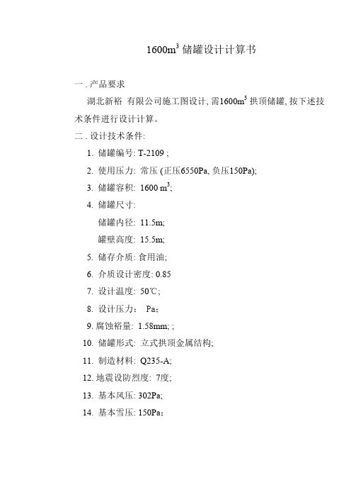
1600m3储罐设计计算书一 . 产品要求湖北新裕有限公司施工图设计, 需1600m3拱顶储罐, 按下述技术条件进行设计计算。
二 . 设计技术条件:1. 储罐编号: T-2109 ;2. 使用压力: 常压 (正压6550Pa, 负压150Pa);3. 储罐容积: 1600 m3;4. 储罐尺寸:储罐内径: 11.5m;罐壁高度: 15.5m;5. 储存介质: 食用油;6. 介质设计密度: 0.857. 设计温度: 50℃;8. 设计压力: Pa;9. 腐蚀裕量: 1.58mm; ;10. 储罐形式: 立式拱顶金属结构;11. 制造材料: Q235-A;12. 地震设防烈度: 7度;13.基本风压: 302Pa;14.基本雪压: 150Pa;三 . 设计计算: (一). 罐壁设计计算:1. 罐壁设计厚度按下列公式计算: Φ=][t 2D P i c σδ (JB/T4735—1997, 式5-1)δ 储罐罐壁的计算厚度( mm);cP 储罐的计算压力(MPa ),根据《钢制焊接常压容器》,其值为设计压力与容器各部位或元件所承受得液柱压力之和。
i D储罐内直径(mm), 11500mm;[]σt 设计温度下罐壁钢板的许用应力(MPa),查JB/T4735—1997表4-1根据中间插值法得130MPa;ϕ焊缝系数, 取0.9;C 1 钢板厚度负偏差(mm), 08mm; C 2 腐蚀裕量(mm), 取1.58mm;2. 先计算底圈罐壁板的壁厚,故Pc =Pi +ρg H ,其中Pi 为储罐设计压力,ρ为储液密度,Hi 为储罐高度,Pc =750+1500×9.8×6.6=0.09777MPa ;δ=9.01302500009777.0⨯⨯⨯ =2.09mm根据JB/T4735—1997中3.5中规定,罐壁的最小厚度为6mm ,故设计厚度为最小厚度和腐蚀裕量之和,取为8mm 。
由于JB/T4735—1997 12.2.1条 规 定 的 D <16m 罐 壁 钢 板 厚 度 应 不 小 于5mm, 所 以底圈 罐 壁 钢 板 厚 度取8mm 。
压缩空气储气罐设计说明书
焊接结构与工艺课程设计学校:山西大同大学煤炭工程学院姓名:**专业:材料成型及控制工程班级:材料一班学号: ************题目:压缩空气储罐设计时间: 2015年12月15日至1月2日指导老师:**大同大学煤炭工程学院前言1、任务说明设计一个压缩空气储罐,采用常规设计方法,综合考虑环境条件等因素并参考相关标准,按工艺设计、设备结构设计、设备强度计算的设计顺序,分别对储罐的筒体、封头、人孔、接管进行设计,然后采用SW6-1998对其进行强度校核,最后形成合理的设计方案。
本设计是针对《焊接结构》这门课程所安排的一次课程设计,是对这门课程的一次总结,要综合运用所学的知识并查阅相关书籍完成设计。
设计基本思路:本设计综合考虑环境条件、介质的理化性质等因素,结合给定的工艺参数,机械按容器的选材、壁厚计算、强度核算、附件选择、焊缝标准的设计顺序,分别对储罐的筒体、封头、人孔接管、人孔补强、接管、管法兰、液位计、鞍座、焊接形式进行了设计和选择。
设备的选择大都有相应的执行标准,设计时可以直接选用符合设计条件的标准设备零部件,也有一些设备没有相应标准,则选择合适的非标设备。
各项设计参数都正确参考了行业使用标准或国家标准,这样让设计有章可循,并考虑到结构方面的要求,合理地进行设计2、压缩空气的性质中文名称:压缩空气主要成分:氮气、氧气等外观与性状:无色无味沸点(℃)-192℃相对密度(水=1):0.9健康危害:无环境危害:无危险特性:高温常压储存,高温剧烈震动易爆特性总结:压缩空气是清晰透明的,输送方便,没有特殊的有害性能,没有起火危害,不怕超负荷,能在许多不利环境下工作,空气在地面上到处都有,取之不尽。
来源:大气中的空气常压为0.1MPa,经过空气压缩机加压后达到理想的压力作用或用途:压缩空气是仅次于电力的第二大动力能源,其应用范围遍及石油,化工,机械,轻工,纺织,国防,科研等行业和部门。
- 1 -大同大学煤炭工程学院目录第一章参数的确定 (3)1.1 设计压力 (3)1.2 设计温度............................ .. (3)1.3 主要元件材料的选择 (3)第二章压力容器结构设计 (5)2.1筒体壁厚计算 (5)2.2封头壁厚计算 (5)2.3压力试验 (7)第三章附件的选择 (8)3.1人孔的选择 (8)3.2人孔补强的计算.......................................... . (8)3.3压力计的选择 (10)3.4选配工艺接管 (11)3.5鞍座的选择 (12)3.5.1 鞍座结构和材料的选取 (12)3.5.2 容器载荷计算 (13)3.5.3 鞍座选取标准 (13)3.5.4 鞍座强度校核 (14)第四章容器焊缝标准 (16)4.1压力容器焊接结构设计要求 (16)4.2筒体与椭圆封头的焊接接头 (16)4.3管法兰与接管的焊接接头 (16)4.4接管与壳体的焊接接头 (17)第五章压缩空气储气罐焊 (17)第六章总结 (21)- 2大同大学煤炭工程学院- 3 -参考文献 (22)第一章 参数的确定1.1 设计压力设计压力为压力容器的设计载荷条件之一,其值不得低于最高工作压力,通常可取最高工作压力的1.05~1.1倍。
20m3立式压缩空气储罐-new
最大允许工作压力 结论
2[ ] e [Pw]= KDi 0.5 e = 0.93941
合格
全 国 化 工 设 备 设 计 技 术 中 心 站
3
过 程 设 备 强 度 计 算 书
SW6-2011
内筒下封头内压计算 计算单位 计算所依据的标准 计算条件 计算压力 Pc 0.90 MPa 设计温度 t 40.00 C 内径 Di 2400.00 mm 曲面深度 hi 600.00 mm 材料 S30408 (板材) t 设计温度许用应力 137.00 MPa 试验温度许用应力 137.00 MPa 钢板负偏差 C1 0.30 mm 腐蚀裕量 C2 0.00 mm 焊接接头系数 0.85 压力试验时应力校核 压力试验类型 试验压力值 压力试验允许通过的应力t 试验压力下封头的应力 校核条件 校核结果 液压试验 PT = 1.25Pc [ ]t = 1.1250
形状系数
6
2h i
计算厚度 有效厚度 最小厚度 名义厚度 结论 重量
h = 2[ ]t 0.5 P c
KPc Di
= 9.29
mm mm mm mm Kg 算 MPa
eh =nh - C1- C2= 9.70 min = 3.60 nh = 10.00 满足最小厚度要求 502.21 压 力 计
立式搅拌容器计算 筒体设计条件 设计压力 p 设计温度 t 内径 Di 名义厚度 n 材料名称 许用应力
t
计算单位 MPa C mm mm
宝鸡忠诚制药机械有限责任公司 内 40 2400 设计 S30408 137 筒 0.9
MPa
137 205
压力试验温度下的屈服点 s 钢材厚度负偏差 C1 腐蚀裕量 C2 厚度附加量 C=C1+C2 焊接接头系数 压力试验类型 试验压力 pT 筒体长度 Lw 内筒外压计算长度 L 封 头 设 计 条 件 封头形式 名义厚度 n 材料名称 设计温度下的许用应力 钢材厚度负偏差 C1 腐蚀裕量 C2 厚度附加量 C=C1+C2 焊接接头系数
空气压缩机额定容量及储气罐容积选择计算

空气压缩机额定容量及储气罐容积选择计算 The manuscript was revised on the evening of 2021空气压缩机额定容量及储气罐容积选择计算(参照EBASCO设计准则)一.空气压缩机额定容量选择1. 不论是仪用或厂用压缩空气,其消耗量以每分钟标态立方米表示(此处标态指国际stp标准:大气压, 气温0℃;此外尚有国际MSC标准中气温15℃,美国15.6℃的),而进入空气压缩机的尚未压缩的空气必须以每分钟实态立方米表示。
2. 设计者经对仪用及厂用压缩空气消耗量分析统计后得到气量的予计的统计值,另加10-20%的裕量后成的为系统消耗气量的设计值。
3. 系统消耗气量设计值加倍后即得到一台空气压缩机额定容量。
在此额定容量下,压缩机50%时间满负荷运转(LOADING),其余50%时间仅维持空转(UNLOADING)。
选择计算示例问题:假设内蒙古苏里格电厂需安装压缩空气系统,其中仪用气供67只气动调节阀用气,厂用气统计为3Nm3/min,,请选定合用系统空气压缩机额定容量?已知:苏里格海拔高度1308m,,年均气压870hPa, 年均气温8℃.解: EBASCO建议数据:气动调节阀耗气量按每只min标态计仪用标态耗气量统计值K NY=67*= Nm3/min厂用标态耗气量统计值K NC= Nm3/min标态耗气量设计值K N=K NY+K NC=(+)*==*= Nm3/min气压气温修正后的实态耗气量K=*(273+8)/273*870=9.81 m3/min (即在空气压缩机进口气体状态下)结论:选定的空气压缩机额定容量为C=*2==20 m3/min 3台二.储气罐容积选择计算1. EBASCO建议数据:A.储气罐的最小容纳时间,取为2分钟(min.)B.储气罐容纳时间期内气压变动为:厂用气 (p2)至 MPa(p1);仪用气EBASCO 要求在 MPa压力下运行,未明确(p2) (p1)的具体数值.。
压缩空气储气罐设计说明书

焊接结构与工艺课程设计学校:山西大同大学煤炭工程学院姓名:**专业:材料成型及控制工程班级:材料一班学号: ************题目:压缩空气储罐设计时间: 2015年12月15日至1月2日指导老师:**大同大学煤炭工程学院前言1、任务说明设计一个压缩空气储罐,采用常规设计方法,综合考虑环境条件等因素并参考相关标准,按工艺设计、设备结构设计、设备强度计算的设计顺序,分别对储罐的筒体、封头、人孔、接管进行设计,然后采用SW6-1998对其进行强度校核,最后形成合理的设计方案。
本设计是针对《焊接结构》这门课程所安排的一次课程设计,是对这门课程的一次总结,要综合运用所学的知识并查阅相关书籍完成设计。
设计基本思路:本设计综合考虑环境条件、介质的理化性质等因素,结合给定的工艺参数,机械按容器的选材、壁厚计算、强度核算、附件选择、焊缝标准的设计顺序,分别对储罐的筒体、封头、人孔接管、人孔补强、接管、管法兰、液位计、鞍座、焊接形式进行了设计和选择。
设备的选择大都有相应的执行标准,设计时可以直接选用符合设计条件的标准设备零部件,也有一些设备没有相应标准,则选择合适的非标设备。
各项设计参数都正确参考了行业使用标准或国家标准,这样让设计有章可循,并考虑到结构方面的要求,合理地进行设计2、压缩空气的性质中文名称:压缩空气主要成分:氮气、氧气等外观与性状:无色无味沸点(℃)-192℃相对密度(水=1):0.9健康危害:无环境危害:无危险特性:高温常压储存,高温剧烈震动易爆特性总结:压缩空气是清晰透明的,输送方便,没有特殊的有害性能,没有起火危害,不怕超负荷,能在许多不利环境下工作,空气在地面上到处都有,取之不尽。
来源:大气中的空气常压为0.1MPa,经过空气压缩机加压后达到理想的压力作用或用途:压缩空气是仅次于电力的第二大动力能源,其应用范围遍及石油,化工,机械,轻工,纺织,国防,科研等行业和部门。
- 1 -大同大学煤炭工程学院目录第一章参数的确定 (3)1.1 设计压力 (3)1.2 设计温度............................ .. (3)1.3 主要元件材料的选择 (3)第二章压力容器结构设计 (5)2.1筒体壁厚计算 (5)2.2封头壁厚计算 (5)2.3压力试验 (7)第三章附件的选择 (8)3.1人孔的选择 (8)3.2人孔补强的计算.......................................... . (8)3.3压力计的选择 (10)3.4选配工艺接管 (11)3.5鞍座的选择 (12)3.5.1 鞍座结构和材料的选取 (12)3.5.2 容器载荷计算 (13)3.5.3 鞍座选取标准 (13)3.5.4 鞍座强度校核 (14)第四章容器焊缝标准 (16)4.1压力容器焊接结构设计要求 (16)4.2筒体与椭圆封头的焊接接头 (16)4.3管法兰与接管的焊接接头 (16)4.4接管与壳体的焊接接头 (17)第五章压缩空气储气罐焊 (17)第六章总结 (21)参考文献 (22)- 2大同大学煤炭工程学院- 3 -第一章 参数的确定1.1 设计压力设计压力为压力容器的设计载荷条件之一,其值不得低于最高工作压力,通常可取最高工作压力的1.05~1.1倍。
压缩空气储罐设计方案
压缩空气储罐设计方案第一章绪论1.1设计背景所谓容器是指用于储存气体、液化气体、液体和固体原料、中间产品或成品的设备。
压力容器是容器的一种,是指最高工作压力P≥0.1MPa,容积V≥25L,工作介质为气体、液化气体或最高工作温度高于或等于标准沸点液体的容器。
它广泛地用于化工、炼油、机械、动力、轻工、纺织、冶金、核能及运输等工业部门,是生产过程中必不可少的设备[1]。
随着石油化工、电站锅炉和原子能工业的迅猛发展,压力容器制造技术也有了很大的发展,它主要表现在以下三个方面:一是压力容器向大型化过渡,容器直径和壁厚成倍增长;二是低合金高强度钢的广泛应用,大部分压力容器均采用了各种级别的低合金高强度钢;三是焊接新工艺、新技术的广泛应用,使得焊接质量进一步提高,从而提高了这些大型产品质量的可靠性。
其中以压力容器产品大型化、高参数化的趋势尤为明显。
1000吨级的储气罐、2000吨级的煤液化反应器、10000立方米的天然气球罐(日本最大的天然气球罐为30000立方米)等已经在我国大量应用。
压力容器在石油化工、核工业、煤化工等领域中的应用场合也日益苛刻。
因此,耐高温、高压和耐腐蚀的压力容器用材料的研制与开发一直是压力容器行业所面临的重大课题。
对此,各国均投入了大量的人力物力从事相关的研究工作。
目前,压力容器用材料的主要研究成果和技术进步表现在以下几个方面:①材料的高纯净度:冶金工业整体技术水平和装备水平的提高,极提高了材料的纯净度,提高了压力容器用材料的力学性能指标,提高了压力容器的整体安全性;②材料的介质适应性:针对各种腐蚀性介质和操作情况,已研究开发出超级不锈钢、双相钢、特种合金等金属材料,使之适合各种应用条件,给容器设计者以更多选择的空间,为长期安全生产提供了保证;③材料的应用界限:针对高温蠕变、回火脆化、低温脆断所进行的研究,准确地给出材料的适用围;④更高强度材料的应用:在设备大型化的要求下,传统的材料已经无法解决,诸如30000立方米天然气球罐、200000立方米原油储罐≥ 800MPa 高强材料的应用正在引起国研以及超高压容器的选材问题。
压缩空气储气罐设计计算
压缩空气储气罐设计计算
压缩空气储气罐设计计算
1 理论背景
压缩空气是一种节能技术,利用某一压强下的空气来调制压力、温度、流量等。
压缩空气储气罐是在压缩机出口建立的一个储气容器,其主要功能是保持压力稳定、减少压力的晃动,同时也可以缓冲压缩机的开闭频率,以达到节能的目的。
2 设计计算步骤
2.1、根据节能需求和压缩机性能,确定压缩机出口端的冲击压力和压力晃动范围;
2.2、选择压缩空气储气罐的形状;
2.3、根据确定好的形状进行储气罐参数的计算,包括储气罐容积、表面积、周长等;
2.4、根据储气罐的表面积以及压缩机出口温度,确定储气罐的厚度;
2.5、根据确定好的容积和厚度,计算储气罐的重量及外形尺寸。
3 注意事项
3.1、储气罐的容积要考虑到压力表的容量;
3.2、储气罐的厚度要考虑到温度变化,应使用较厚的材料;
3.3、储气罐的尺寸要根据压缩机的出口端口位置和安装方式进行定型;
3.4、储气罐必须安装压力表,用来监测储气罐内压力的变化;
3.5、在储气罐的上部应安装滤清器,以防止外界的杂质污染压缩空气;
3.6、储气罐的外表必须与环境保持一致,并应具备防爆的功能。
20m3压缩空气罐安全阀计算书
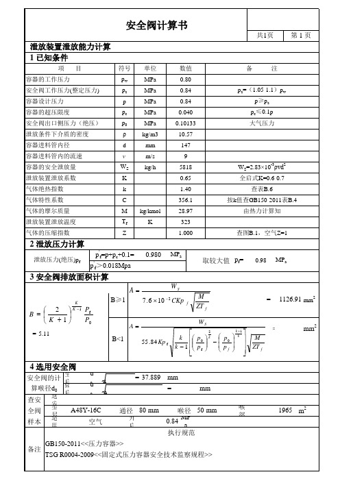
共1页 第1页
泄放装置泄放能力计算 1 已知条件
项 容器的工作压力 安全阀工作压力(整定压力) 容器设计压力 容器的超压限度 安全阀出口侧压力(绝压) 泄放条件下介质的密度 容器进料管内径 容器进料管内的流速 容器的安全泄放量 泄放装置泄放系数 气体绝热指数 气体特性系数 气体的摩尔质量 泄放装置泄放温度 气体的压缩指数 目 符号 pw pz p pc p0 ρ d v WS K k C M Tf Z kg/kmol K 单位 MPa MPa MPa MPa MPa kg/m3 mm m/s kg/h 数值 0.80 0.84 0.84 0.040 0.10133 10.57 147 9 5818 0.65 1.40 356.1 28.97 323 1.000 查图B.1,空气Z=1 WS=2.83× -3ρvd2 10 全启式K=0.6-0.7 查表B.6 按k值查GB150-2011表B.4 由热力计算知 pz=(1.05-1.1)pw p≥pz pc≤0.1p 大气压力 备 注
2 泄放压力计算
泄放压力(绝压)pf
p'f=p+pc+0.1= p'f>0.018Mpa
0.980
MPa
取较大值 pf=
0.98
MPa
3 安全阀排放面积计算
A WS 7 . 6 10 2 CKp
AfLeabharlann 2 B K 1= 5.11
K K 1
B≥1
Pf P0
B<1
M ZT f
WS
=
1126.91 mm2
55 .84 Kp f
k 1 2 p0 k p0 k k p k 1 p f f
压缩空气储气罐设计说明书
焊接结构与工艺课程设计学校:山西大同大学煤炭工程学院姓名:**专业:材料成型及控制工程班级:材料一班学号: ************题目:压缩空气储罐设计时间: 2015年12月15日至1月2日指导老师:**大同大学煤炭工程学院前言1、任务说明设计一个压缩空气储罐,采用常规设计方法,综合考虑环境条件等因素并参考相关标准,按工艺设计、设备结构设计、设备强度计算的设计顺序,分别对储罐的筒体、封头、人孔、接管进行设计,然后采用SW6-1998对其进行强度校核,最后形成合理的设计方案。
本设计是针对《焊接结构》这门课程所安排的一次课程设计,是对这门课程的一次总结,要综合运用所学的知识并查阅相关书籍完成设计。
设计基本思路:本设计综合考虑环境条件、介质的理化性质等因素,结合给定的工艺参数,机械按容器的选材、壁厚计算、强度核算、附件选择、焊缝标准的设计顺序,分别对储罐的筒体、封头、人孔接管、人孔补强、接管、管法兰、液位计、鞍座、焊接形式进行了设计和选择。
设备的选择大都有相应的执行标准,设计时可以直接选用符合设计条件的标准设备零部件,也有一些设备没有相应标准,则选择合适的非标设备。
各项设计参数都正确参考了行业使用标准或国家标准,这样让设计有章可循,并考虑到结构方面的要求,合理地进行设计2、压缩空气的性质中文名称:压缩空气主要成分:氮气、氧气等外观与性状:无色无味沸点(℃)-192℃相对密度(水=1):0.9健康危害:无环境危害:无危险特性:高温常压储存,高温剧烈震动易爆特性总结:压缩空气是清晰透明的,输送方便,没有特殊的有害性能,没有起火危害,不怕超负荷,能在许多不利环境下工作,空气在地面上到处都有,取之不尽。
来源:大气中的空气常压为0.1MPa,经过空气压缩机加压后达到理想的压力作用或用途:压缩空气是仅次于电力的第二大动力能源,其应用范围遍及石油,化工,机械,轻工,纺织,国防,科研等行业和部门。
- 1 -大同大学煤炭工程学院目录第一章参数的确定 (3)1.1 设计压力 (3)1.2 设计温度............................ .. (3)1.3 主要元件材料的选择 (3)第二章压力容器结构设计 (5)2.1筒体壁厚计算 (5)2.2封头壁厚计算 (5)2.3压力试验 (7)第三章附件的选择 (8)3.1人孔的选择 (8)3.2人孔补强的计算.......................................... . (8)3.3压力计的选择 (10)3.4选配工艺接管 (11)3.5鞍座的选择 (12)3.5.1 鞍座结构和材料的选取 (12)3.5.2 容器载荷计算 (13)3.5.3 鞍座选取标准 (13)3.5.4 鞍座强度校核 (14)第四章容器焊缝标准 (16)4.1压力容器焊接结构设计要求 (16)4.2筒体与椭圆封头的焊接接头 (16)4.3管法兰与接管的焊接接头 (16)4.4接管与壳体的焊接接头 (17)第五章压缩空气储气罐焊 (17)第六章总结 (21)- 2大同大学煤炭工程学院- 3 -参考文献 (22)第一章 参数的确定1.1 设计压力设计压力为压力容器的设计载荷条件之一,其值不得低于最高工作压力,通常可取最高工作压力的1.05~1.1倍。
压缩空气储气罐容量计算

压缩空气储气罐容量计算说起来压缩空气储气罐这容量计算啊,还真是个技术活,但咱也别把它想得太玄乎。
我呢,虽说是个写东西的,但平日里也喜欢鼓捣点这些技术玩意儿,权当是给自己找乐子。
这不,今儿个咱们就来聊聊这储气罐容量计算那点事儿。
先说说这储气罐吧,它长得就跟个大胖子似的,圆滚滚的,上面焊着几个阀门,就像人身上的肚脐眼儿,各有各的用处。
有的阀门负责进气,有的负责出气,还有的,是安全阀,关键时刻能保命。
每次我看到这些阀门,就想起小时候村里的大磨盘,也是一圈一圈的,各有各的转法,挺有意思的。
咱们言归正传,说说这容量计算。
其实啊,计算储气罐的容量,就跟咱们平时量米做饭差不多,只不过这“米”换成了空气,容器换成了储气罐。
首先呢,你得知道你要存多少空气,这就得看你的需求了。
比如说,你要是个小作坊,用气量不大,那储气罐也就不用太大;但你要是个大工厂,整天轰隆隆的,那储气罐就得像个胖子一样,吃得饱饱的才行。
在计算容量的时候,还有个关键参数,就是压力。
这压力啊,就像是人的脾气,有的大有的小,储气罐里的空气也是,有的压力大,有的压力小。
压力大的时候,空气就被压得紧紧的,占的地方就小;压力小的时候,空气就松松垮垮的,占的地方就大。
所以啊,在计算容量的时候,咱们得把这个压力因素考虑进去。
我记得有一次,我去一家工厂参观,那儿的工程师正忙着计算储气罐的容量。
我看他拿着个计算器,噼里啪啦地按个不停,眉头紧锁,一脸严肃。
我走过去,拍了拍他的肩膀,说:“小伙子,别太紧张了,这计算嘛,就像咱们平时聊天,得轻松愉快才行。
”他抬头看了看我,苦笑了一下,说:“刘老师,您说得轻巧,这计算要是出了差错,那可就是大事啊。
”我笑了笑,说:“没错,计算是得认真,但也得有乐趣。
你想啊,这储气罐就像是个大气球,你给它吹气,它就鼓起来,你放气,它就瘪下去。
这计算的过程,就像是你在给这个大气球打气,你得知道要打多少气,才能让它既不爆炸,也不瘪下去。
这其中的乐趣,你可得好好体会啊。
压缩空气储气罐选型计算
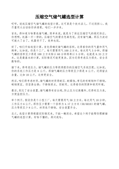
压缩空气储气罐选型计算哎呀,说起压缩空气储气罐的选型计算,这可真是个技术活儿。
不过别担心,我尽量用大白话给你讲清楚,咱们一步步来。
首先,得知道为啥要选储气罐。
简单来说,就是为了保证压缩空气的稳定供应。
你想啊,机器一开一停的,压缩空气的需求忽高忽低,没有储气罐,那压力波动可就大了去了,机器受不了,效率也低。
好了,咱们开始选型计算。
首先得确定储气罐的容积,这得看你的用气量和用气频率。
比如说,你是个工厂,每天需要用气100立方米,每次用气5分钟,那储气罐的容积至少得是100立方米除以60分钟再乘以5分钟,也就是8.33立方米。
这是最基本的计算,实际情况可能更复杂,因为还得考虑压力损失、安全系数啥的。
接下来,得考虑压力。
储气罐的压力等级得跟你的压缩空气系统匹配。
比如说,你的系统工作压力是8公斤,那储气罐的压力等级至少得是8公斤,还得留点余量,比如10公斤,这样更安全。
然后,咱们得考虑材质。
储气罐的材质得耐压、耐腐蚀。
常见的有碳钢和不锈钢。
碳钢便宜,但容易生锈;不锈钢贵点,但耐用。
这得看你的预算和使用环境。
最后,别忘了安全装置。
储气罐得有安全阀,防止压力过高爆炸。
还得有压力表,方便监控压力。
举个例子,假设你是个小型工厂,每天需要用气50立方米,每次用气10分钟,工作压力6公斤。
那你至少需要一个容积为4.17立方米(50/6010)的储气罐,压力等级至少8公斤,材质选不锈钢,安全装置齐全。
总之,选型计算得根据实际情况来,不能一概而论。
希望这个例子能帮你理解储气罐的选型计算。
有啥不懂的,再问我哈。
ASME计算书2014.1.3

压缩空气罐的设计计算DESIGN CALCULA TIONS OF COMPRESSED AIR STORAGE TANK设计规范:ASME规范第Ⅷ卷第1册,2013年版Design Code: ASME Code Section ⅧDivision 1,2013 Edition工作令号:Work Number:图号:ASME14-001 Rev.0Drawing No.:ASME14-001 Rev.0江苏星瑞化工工程科技有限公司Jiangsu Sunrise Chemical Engineering T echnology Co.,Ltd目录Content封面 1 Cover目录 2 ContentA.设计参数和条件 3 Design parameters and the conditionB.基本材料许用应力的选取及其依据 4 Selection of base material, allowable stresses and its basisC.强度计算 4 Strength Calculations1.壳体壁厚的计算列表 4 Calculation Tabulation of cylindrical shell wall thickness2.椭圆形封头的壁厚计算 5 Wall thickness calculations for ellipsoidal heads3.人孔圈的计算7 Calculation of manhole ring4.接管计算(依照UG-45)8 Calculation of nozzles(according to UG-45)5.开孔补强计算10 Calculation of opening reinforcement6.接管角焊缝尺寸计算13 Calculation for fillet welding size of nozzles7. 法兰与接管颈部的焊缝计算14Calculation for flange to nozzle neck welds8.人孔附件焊接强度16 Checking of welding joint strength of the attachment of manholeD.标准件的选取17 Selection of standard partsE.液压试验压力及校核17 Hydrotest pressure and stress checkingF.判定对冲击试验的要求18 Judgements whether the impact test is requiredG.判定对冷作成型后热处理的要求19 Judgement for whether heat treatment shall be carried out after cold forming H.焊后热处理检测20 Check of post weld heat treatmentI.无损检测要求21 Required NDE附录:21 AppendixA 鞍座的计算22 The calculation of saddle supportsB 容器载荷要求(ASME-Ⅷ-1 UG-22 & UG-54)29-30 V essel loading requirements (ASME sect.ⅧDiv. 1, UG-22&UG-54)A.设计参数和条件:Design parameters and the condition结构草案和设计计划参照用户设计技术条件ABC/2013 Rev.0Structural sketch and design plan are referred to The Customer Design Specification And Drawings ABC/2013 Rev.0工作令号:@@@ 图号:ASME13-001 ,Rev.0Work No:@@@@ Dwg. No:ASME13-001 ,Rev.0设计规范:ASME 规范第Ⅷ卷第1册(2013年版)Design code: ASME Code Sect.Ⅷ.Div.1(2013.Ed)容器载荷依据UG-22V essel loadings per UG-22操作压力:0.5MPaOperating pressure:0.5MPa操作温度:0~40℃Operating temperature:0~40℃介质:压缩空气(非致命性)Service Fluid:Compressed air (Non-lethal)射线检测要求:抽样射线检测(A、B类,其他按标准)NDE requirements: spot RT(A、B category,other per Code)焊接接头系数:0.85 for shell & headJoint efficiency: 0.85 for shell & head设计压力:0.6MPaDesign pressure:0.6MPa设计温度:50℃Design temperature:50℃最小设计金属温度:0℃at 1.2MPaMin. design metal temperature(MDMT):0℃at 1.2MPa最大许用工作压力:1.2MPa at 50℃MAWP: 1.2MPa at 50℃腐蚀裕量:1.0mmCorrosion allowance:1.0mm水压试验压力:1.56MpaHydrostatic test pressure:1.56Mpa焊后热处理:NO,per UCS-56Postweld heat treatment:NO,per UCS-56冲击要求:NO,per UG-20(f) AND UCS-66IMPact require:NO,per UG-20(f) AND UCS-66名义容积:1.48m3Nominal volume:1.48m3基本材料: SA-516M Gr.485 筒体和封头板(Shell and Head plate)Base material: SA-106M Gr.B接管(Pipe)SA-105M 法兰(Flange)B.基本材料,许用应力的选取及其依据Selection of base material, allowable stresses and its basis(a)壳体,封头和人孔圈(由钢板轧制而成)的材料:SA-516M Gr.485Material of shell course, head and manhole ring(rolled with plate): SA-516M Gr.485 它在设计温度下的最大许用应力为:Its max. allowable stresses at the design temperature is:S=138MPa(b)对于作为承压元件的接管材料,采用SA-106M Gr.B。
压缩机缓冲罐计算
压缩机缓冲罐计算压缩机缓冲罐是一种用于储存和平衡压缩机系统中压缩空气的设备。
它的主要作用是减少压缩机启停时的脉动和压力波动,提供稳定的压缩空气供应,并保护压缩机免受过大压力和频繁启停造成的损坏。
下面是压缩机缓冲罐计算的详细说明:1. 确定所需的缓冲罐容积:缓冲罐容积的大小取决于以下几个因素:- 压缩机排气流量:根据压缩机的额定流量确定。
- 工作压力范围:考虑工作压力的最小值和最大值。
- 压缩机的启停频率:启停频率越高,所需的缓冲罐容积越大。
2. 计算罐内空气贮存量:罐内的空气贮存量可以通过以下公式计算:V = (P1 - P2) * V1 / (P0 - P2)其中,V为缓冲罐容积(单位为立方米),P1为最大工作压力(单位为帕斯卡),P2为最小工作压力(单位为帕斯卡),V1为每分钟的排气流量(单位为立方米/分钟),P0为大气压(单位为帕斯卡)。
3. 考虑罐内水平变化:由于缓冲罐中的空气和液体(通常是水)在使用过程中会发生水平变化,需要根据实际情况调整缓冲罐容积。
一般来说,建议将容积增加10-20%以确保足够的空间。
4. 确定缓冲罐的尺寸和形状:根据计算得到的缓冲罐容积,选择适当的尺寸和形状。
常见的缓冲罐形状包括圆柱形、球形和椭球形。
确保缓冲罐的尺寸符合安装要求,并考虑到操作和维护的方便性。
5. 安装和调试:根据缓冲罐的尺寸和形状,选择合适的安装位置,并确保与压缩机系统的管道连接正确。
在安装完成后,进行必要的调试和测试,确保缓冲罐能正常运行并达到预期效果。
需要注意的是,以上计算和步骤仅为一般参考,实际应用中可能会有特定要求和情况需要考虑。
建议在计算和选择缓冲罐时,咨询专业的工程师或压缩机制造商,以确保系统的安全和稳定运行。
压缩空气罐计算书
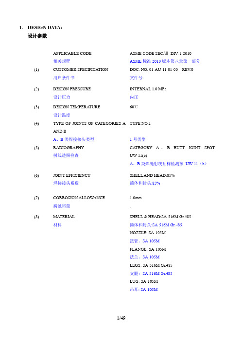
1.DESIGN DATA:设计参数(1) APPLICABLE CODE相关规程CUSTOMER SPECIFICATION用户条件书ASME CODE SEC.ⅧDIV. 1 2010ASME标准2010版本第八章第一部分DOC. NO. 01-AU-11-01-00 REV.0文件号:(2) DESIGN PRESSURE设计压力INTERNAL 1.0 MPa 内压(3) DESIGN TEMPERA TURE设计温度60℃(4) TYPE OF JOINTS OF CA TEGORIES AAND BA、B类焊接接头类型TYPE NO.1 1号类型(5) RADIOGRAPHY射线透照检查CA TEGORY A、B BUTT JOINT SPOT UW-11(b)A、B类焊缝射线抽样检测按UW-11(b)(6) JOINT EFFICIENCY焊接接头系数SHELL AND HEAD:85% 筒体和封头:85%(7) CORROSION ALLOWANCE腐蚀裕量1.0mm .(8) MATERIAL材料SHELL & HEAD:SA-516M Gr.485 筒体和封头:SA-516M Gr.485 NOZZLE: SA-105M接管:SA-105MFLANGE: SA-105M法兰:SA-105MLEGS:SA-516M Gr.485支腿:SA-516M Gr.485LUG: SA-105M吊耳: SA-105M(9) MAX. ALLOWABLE STRESS A TDESIGN TEMPERA TURE设计温度下的最大许用应力SA-516M Gr.485: 138MPa at 60℃SA-105M: 138MPa at 60℃(10) MATERIAL UNDERTOLERANCESHELL AND HEAD筒体和封头材料的厚度负偏差<0.25mm(11) HEAD TYPE封头类型2:1 S.E.(12) TANK CAPACITY罐容积4.9 m³(13) SERVICE FLUID工作介质COMPRESSED AIR (no lethal) 压缩空气(非致死)(14) MIN. SERVICE TEMPERA TURE最低操作温度0℃at 1.0MPa(15) THE LOADING CONSIDERED INDESIGNING设计中所考虑的载荷SEE TABLE 1-1见表1-1(16) TANK DIMENSIONS容器尺寸SEE FIG. 1-1 见图1-1TABLE 1-1 LOADING CONSIDERED IN DESIGNING 表1-1 设计过程中考虑的负载问题LIST OF NOZZLES 接管明细表2、TANK CAPACITY CHECKED罐容量审查The volume of head is given by封头体积计算公式:V head = 0.1309 × Di3= 0.1309 ×1.43= 0.359m3Where Di = Inside diameter of vessel, m;Di=容器内径V head = V olume of elliptical dished head to tangent Line, m3V head =椭圆中凹封头到切线的体积The volume of shell is given by壳体体积计算公式:V shell = 1/4 ×π× D2 × L= 1/4 ×π× (1.4) 2 ×2.82= 4.339m3Where D = Inside diameter of shell, mD=壳体内径L = Length of shell tangent to tangent, mL=壳体两切线间的长度V shell = V olume of shell, m3V shell =壳体的体积The total volume of vessel is容器的总体积计算方法是:V total =0.359× 2 +4.339= 5.057m3> 4.9 m3(REQUIRED用户要求) OK3、THICKNESS OF CYLINDRICAL SHELL UNDER INTERNALPRESSURE内压作用下的筒体厚度ASME SEC.ⅧDIV.1 UG-27 ASME第八章节第一部分UG-27●Part部件: Shell筒体●Design pressure设计压力P (MPa) : 1.0●Design temperature设计温度(℃) : 60●Material材料: SA-516M Gr.485 ●Maximum allowable stress value at design temperature设计温度下最大许用应力值S d(MPa) : 138●Maximum allowable stress value at test temperature试验温度下最大许用应力值S t(MPa) : 138●Height to point under consideration到上封头接管密封面的距离H (m) : 3.305●Density of test medium at test temperature试验温度下试验介质的密度g t(Kg/m3) : 1000●Type of welded joints in TABLE UW-12焊接接头类型按表UW-12: Type No. (1)●Radiographic examination射线透照检查: SPOT●Joint efficiency (specified in UW-12)焊接接头系数(按UW-12)E : 0.85●Corrosion allowance腐蚀裕量C (mm) : 1●Inside radius corroded考虑腐蚀的内径R (mm) : 701●Final center line radius最终中心线半径R f (mm) : 706●Original center line radius成形前中心线半径R o (mm) : ∞(1) Minimum required thickness (circumferential stress)最小厚度(环向应力)0.385SE = 0.385×(138)×(0.85) =45.16 > P (a) For operating condition操作工况PE S PRd 6.0t 1-=.16.085.01387010.1⨯-⨯⨯=6.007m m =(b) For hydrostatic test condition水压试验工况662108.96.0108.96.0 t tt tt Hg E S R Hg P E S PR -+-= 66101000305.38.96.085.0138701101000305.38.916.085.01387011⨯⨯⨯-⨯⨯⨯⨯+⨯-⨯⨯= m m 201.60.1946.007 =+=(2) Design thickness设计厚度t=Greater of (t1 or t2) +C 取较大值 = t 2+C =7.2mm(3) Provided thickness验证厚度Nominal thickness (mm)12> t OK 名义厚度 12mm> t OK(4) Check minimum required thickness for paragraph UG-16 (b) (4)按UG-16 (b) (4)校核最小厚度Minimum thickness required (including corrosion allowance) is 3.5mm,所需最小厚度(包括腐蚀裕量)是3.5mm nominal thickness is 12mm>3.5mm OK 名义厚度是12mm>3.5mm 合格Due to E=0.85>0.5, longitudinal stress can not affect the thickness of the wall. 因为E=0.85>0.5 所以纵向应力不是决定壁厚的因素。
- 1、下载文档前请自行甄别文档内容的完整性,平台不提供额外的编辑、内容补充、找答案等附加服务。
- 2、"仅部分预览"的文档,不可在线预览部分如存在完整性等问题,可反馈申请退款(可完整预览的文档不适用该条件!)。
- 3、如文档侵犯您的权益,请联系客服反馈,我们会尽快为您处理(人工客服工作时间:9:00-18:30)。
[Pw]= =1.16051
MPa
设计温度下计算应力
t= =138.43
MPa
t
160.65
MPa
校核条件
t≥t
结论
合格
内筒上封头内压计算
计算单位
计算条件
椭圆封头简图
计算压力Pc
1.00
MPa
设计温度t
100.00
C
内径Di
2400.00
mm
曲面高度hi
600.00
mm
材料
Q345R (板材)
64
mm2
A1+A2+A3=1610mm2,小于A,需另加补强。
补强圈面积A4
2716
mm2
A-(A1+A2+A3)
1856
mm2
结论:补强满足要求。
2400.00
mm
材料
Q345R(板材)
试验温度许用应力
189.00
MPa
设计温度许用应力t
189.00
MPa
试验温度下屈服点s
345.00
MPa
钢板负偏差C1
0.30
mm
腐蚀裕量C2
1.00
mm
焊接接头系数
0.85
厚度及重量计算
计算厚度
= = 7.49
mm
有效厚度
e=n-C1- C2--C3=8.70
软件批准号:CSBTS/TC40/SC5-D01-1999
DATA SHEET OF PROCESS EQUIPMENT DESIGN
工程名:
PROJECT
设备位号:
ITEM
设备名称:压缩空气储罐
EQUIPMENT
图号:ZL319.00
DWG NO。
设计单位:
DESIGNER
设计
日期
校核
日期
审核
日期
设计温度许用应力t
189.00
MPa
试验温度许用应力
189.00
MPa
钢板负偏差C1
0.30
mm
腐蚀裕量C2+冲压减薄量C3
2.00
mm
焊接接头系数
1.00
厚度及重量计算
形状系数
K= =1.0000
计算厚度
= = 6.36
mm
有效厚度
e=n-C1- C2-C3=7.70
mm
最小厚度
min=3.60
mm
mm
补强圈强度削弱系数frr
1
接管材料强度削弱系数fr
1
开孔直径d
462.6
mm
补强区有效宽度B
925.2
mm
接管有效外伸长度h1
68.01
mm
接管有效内伸长度h2
0
mm
开孔削弱所需的补强面积A
3466
mm2
壳体多余金属面积A1
558.4
mm2
接管多余金属面积A2
988.1
mm2
补强区内的焊缝面积A3
审定
Approved by
日期
立式搅拌容器校核
计算单位
筒体设计条件
内筒
设计压力p
MPa
1
设计温度t
C
100
内径Di
mm
2400
名义厚度n
mm
10
材料名称
Q345R
许用应力
189
t
MPa
189
压力试验温度下的屈服点
345
钢材厚度负偏差C1
mm
0.3
腐蚀裕量C2
mm
1
厚度附加量C=C1+C2
mm
1.3
焊接接头系数
0.85
压力试验类型
液压
试验压力pT
MPa
1.25
筒体长度Lw
mm
3200
内筒外压计算长度L
mm
封头设计条件
筒体上封头
筒体下封头
夹套封头
封头形式
椭圆形
椭圆形
名义厚度n
mm
10
10
材料名称
Q345R
Q345R
设计温度下的许用应力t
MPa
189
189
钢材厚度负偏差C1
mm
0.3
0.3
腐蚀裕量C2+冲压减薄量C3
Q345R
板材
壳体开孔处焊接接头系数φ
0.85
壳体内直径Di
2400
mm
壳体开孔处名义厚度δn
10
mm
壳体厚度负偏差C1
0.3
mm
壳体腐蚀裕量C2
1mm壳体材料源自用应力[σ]t189MPa
接管实际外伸长度
195
mm
接管实际内伸长度
0
mm
接管材料
Q345R
接管焊接接头系数
0.85
名称及类型
板材
接管腐蚀裕量
名义厚度
n=10.00
mm
结论
满足最小厚度要求
重量
508.15
Kg
压力计算
最大允许工作压力
[Pw]= =1.21081
MPa
结论
合格
内筒下封头内压计算
计算单位
计算条件
椭圆封头简图
计算压力Pc
1.00
MPa
设计温度t
100.00
C
内径Di
2400.00
mm
曲面高度hi
600.00
mm
材料
Q345R (板材)
设计温度许用应力t
189.00
MPa
试验温度许用应力
189.00
MPa
钢板负偏差C1
0.30
mm
腐蚀裕量C2+冲压减薄量C3
2.00
mm
焊接接头系数
1.00
厚度及重量计算
形状系数
K= =1.0000
计算厚度
= = 6.36
mm
有效厚度
e=n-C1- C2-C3=7.70
mm
最小厚度
min=3.60
mm
mm
2
2
厚度附加量C=C1+C2
mm
2.3
2.3
焊接接头系数
1
1
主要计算结果
内圆筒体
内筒上封头
内筒下封头
校核结果
校核合格
校核合格
校核合格
质量mkg
1901.84
508.15
508.15
搅拌轴计算轴径mm
备注
内筒体内压计算
计算单位
计算条件
筒体简图
计算压力Pc
1.00
MPa
设计温度t
100.00
C
内径Di
mm
名义厚度
n=10.00
mm
重量
1901.84
Kg
压力试验时应力校核
压力试验类型
液压试验
试验压力值
PT= 1.25P =1.2500(或由用户输入)
MPa
压力试验允许通过
的应力水平T
T0.90s=310.50
MPa
试验压力下
圆筒的应力
T= =203.58
MPa
校核条件
TT
校核结果
合格
压力及应力计算
1
mm
补强圈材料名称
Q345R
凸形封头开孔中心至
封头轴线的距离
mm
补强圈外径
760
mm
补强圈厚度
10
mm
接管厚度负偏差C1t
0.3
mm
补强圈厚度负偏差C1r
0.3
mm
接管材料许用应力[σ]t
189
MPa
补强圈许用应力[σ]t
189
MPa
开孔补强计算
壳体计算厚度δ
7.493
mm
接管计算厚度δt
1.436
名义厚度
n=10.00
mm
结论
满足最小厚度要求
重量
508.15
Kg
压力计算
最大允许工作压力
[Pw]= =1.21081
MPa
结论
合格
开孔补强计算
计算单位
接管:m,φ480×10
计算方法: GB150-1998等面积补强法,单孔
设计条件
简图
计算压力pc
1
MPa
设计温度
100
℃
壳体型式
圆形筒体
壳体材料
名称及类型