液压维修手册
叉车液压系统维修手册

叉车液压系统维修手册第一节介绍叉车液压系统叉车液压系统是叉车的核心部件之一,其主要功能是提供驱动力和控制叉车的升降、倾斜及其他运动。
液压系统中,液压泵从油箱抽取液压油,通过液压阀控制液压油的流动,在执行机构产生相应的动作。
本章节将详细介绍叉车液压系统的组成和工作原理。
第二节液压系统故障诊断与维修叉车液压系统故障会导致叉车无法正常工作,影响工作效率和安全性。
本节将以常见的液压系统故障为例,介绍如何进行故障诊断和维修。
2.1 液压系统故障的分类液压系统故障可以分为液压油泄漏、液压泵故障、液压阀故障、执行机构故障等多个方面。
我们将针对不同类型的故障进行详细的分析和解决方案。
2.2 液压系统故障的诊断液压系统故障的诊断是解决故障的第一步。
我们将介绍一些常见的故障表现和对应的诊断方法,以帮助您快速准确地找到故障原因。
2.3 液压系统故障的维修在诊断出液压系统故障原因后,我们需要进行相应的维修措施。
本节将详细介绍如何正确地维修叉车液压系统,包括更换液压油封、清洗液压阀等。
第三节液压系统维护与保养对叉车液压系统进行定期维护和保养是确保其正常工作和延长使用寿命的关键。
本节将介绍叉车液压系统的维护和保养要点,帮助您更好地管理和保养叉车液压系统。
3.1 液压油的更换液压油的清洁度和合理的粘度对液压系统的正常运行至关重要。
我们将介绍液压油更换的步骤和注意事项,确保液压油的正常使用。
3.2 液压系统的清洁液压系统的清洁可以有效预防故障和维护系统的正常运行。
本节将介绍液压系统清洗的方法和注意事项,帮助您进行系统清洁。
3.3 液压系统的润滑润滑是液压系统保持良好工作状态的重要环节。
我们将介绍叉车液压系统中需要润滑的部位和选用润滑剂的注意事项。
结语本手册对叉车液压系统的维修和保养进行了详尽的介绍,希望能够帮助您更好地理解和操作液压系统,并在实际工作中解决液压系统故障。
请在维修和保养时严格按照手册中的要求进行操作,确保工作安全和叉车的正常运行。
液压、气压或润滑系统维修指南说明书
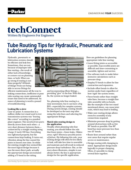
Hydraulic, pneumatic or lubrication systems should be efficient and leak free. Sometimes, they are not, because of improper tube line routing—the result of either lack of knowledge, or corners cut on planning time, or both. What can go wrong if routing is not done properly? All kinds of things! From not being able to access fittings forefficient maintenance all the way to leaking connections, inefficient or poor tube routing can create unintended issues that need to be addressed. An ounce of planning is worth a pound of troubleshooting.Leaking like a sieveCase-in-point: A connection in a million-dollar test stand used to test transmission systems was “leaving like a sieve” according to a puzzled plant engineer. This involved two ports directly across from each other—a very short distance between them—connected by a straight routing using a large (2-inch) OD line. Everything was tightened properly, but theconnections kept leaking. It turns out, vibration along the line caused the joints to loosen over time. So while the existing straight line seemed like the most logical design because it was the most direct path, actually the appropriate design necessitated adding a U-bend in the tubingTube Routing Tips for Hydraulic, Pneumatic and Lubrication SystemsTube Routing Tips for Hydraulic, Pneumatic and Lubrication SystemstechConnectWritten By Engineers For Engineersand incorporating elbow fittings—providing “give” to the line. With this fix, the system no longer leaked. Yes, planning tube line routing is a time investment, but it can have a big ROI—especially for complex systems. During system design, routing should be developed as the next step aftersizing the tube lines and selecting theappropriate fittings.Match tube routing design tothe applicationUsually, when planning tube linerouting, you should follow the rulethat fewer joints = fewer leaks. (Makessense, right? Minimize possible points of failure.) By following this rule, your routing design will often be less likely to leak, will take less time to assemble and maintain and will result in reduced pressure drop/turbulence. But, as the story above illustrates, simpler is not always better; the key is appropriate design for the specific application.Here are guidelines for planning appropriate tube line routing: • L eave fitting joints as accessible as possible. Inaccessible joints are difficult and time-consuming to assemble, tighten and service.• U se software tools to make labor-intensive calculations such as pressure drop.• E mploy U-bends to allow for line contraction and expansion.• I nclude offset bends to allow formotion under load, regardless of how ‘rigid’ the system seems.• F avor bends rather than straighttube lines, because a straight linetube assembly with no bends, like the example of the test stand mentioned above, can cause joint stain, which may lead to leaking.• M ake sure routing design allowsroom for assembly of anyconnections required.• M inimize pressure drop by getting around obstructions with as few 90° bends as possible. One 90° bend has more pressure loss than two 45° bends.• R oute lines around rather than over areas that require regular access or maintenance.• D esign routing with clamping in mind. Appropriate design leads logically to proper clamping. Often, it’s possible to clampseveral lines together.Parker Hannifin Corporation Tube Fittings Division 3885 Gateway Blvd.Columbus, OH 43228phone 614 279 7070fax 614 279 /tfd© 2016 Parker Hannifin Corporation 03/2016Tube Routing Tips for Hydraulic, Pneumatic and Lubrication Systems• K eep troubleshooting andmaintenance in mind: focus onlogical design and avoid crossed lines.• D esign the tube line routing toreduce likelihood of users standing or climbing on plumbing.So, although generally speaking you want to minimize joints, the the best (most efficient, least likely to leak) path for connecting tubing from one point to another isn’t always the most direct.And finally, proper line routing isn’t just a matter of optimal function, but also achieving a neat appearance. Gooddesign is something you can be proud of.Resources and next stepsFor more line routing tips, download Parker’s detailed bulletinDry Technology - The Guide to Leak-free Connections.With proper line routing in place, the next step is to assure adequate tube line support (aka clamping). We’ll cover this in a follow-up techConnect post.If you have any questions or comments, please post them and we will respond if warranted. To talk to our techConnect engineer team directly, they can be reached at Parker Tube Fittings Division, 614.279.7070.Ted AmlingSr. Project EngineerParker Tube Fittings Division For more TechConnect articles, visit .Tube routing summary。
液压系统使用及维护和检修手册

液压系统使用及维护和检修手册液压系统是一种利用液压介质传递动力的系统,广泛应用于机械、工程、建筑等领域。
正确的使用、维护和检修液压系统,可以延长系统的使用寿命,提高工作效率,降低损耗。
本手册将介绍液压系统的使用、维护和检修技巧,帮助您更好地了解和掌握液压系统的操作和维护。
一、液压系统的基本构成液压系统包括液压泵、液压缸、液压阀、储油箱、油管等组成。
液压泵将液体压力转换为机械能,供给液压缸。
液压缸经过液压阀控制,使液体发挥出各种作用:1.推动、拉动或升降重物。
2.控制旋转或直线运动的速度和方向。
3.瞬时阻尼或过载保护。
4.对工作液进行过滤、冷却和保护自动化。
二、液压系统的使用1.确保储油箱中的油液充足,油品符合要求,油温适当。
2.在使用前检查液压系统是否存在漏油现象,如有,请及时检查并加以处理。
3.清洁液压系统中的过滤器和油管,确保系统油流畅通。
4.在使用液压系统过程中,必须注意阀门的开关顺序,不能使液压系统产生压力过高、溢流等失控现象。
5.避免液压系统过载,按照工作要求选择适当的液压泵和液压缸。
6.使用液压系统时,应掌握操作规程和注意事项,遵循相关规定。
三、液压系统的维护1.定期更换油品,控制液压系统的油温。
2.清洗液压系统中的各种过滤器和油管,确保系统畅通。
3.定期检查所有液压元件的紧固度和泄漏情况,并及时更换各种密封元件。
4.定期对液压系统进行清洗、加油和防腐处理。
5.定期对液压泵和液压缸进行检修和维护。
四、液压系统的检修1.检查液压系统是否存在外漏现象,修复泄漏部位。
2.检查液压阀的安装、接口和各部件是否正常,如有异常,及时处理。
3.检查液压缸的活塞杆和密封圈,如发现磨损或损坏,更换相应零件。
4.对液压泵、阀门和其他液压元件进行清洗、检修和维护。
5.在检修液压系统时,确保油箱中的油液已经放空,避免油液的浪费和环境的污染。
五、液压系统的安全注意事项1.当液压系统工作时,请勿放置杂物或者缩小操作范围,以免发生危险。
液压维修手册

液压维修手册1. 引言液压系统在各个行业中广泛应用,包括工业制造、农业、建筑和航空等。
液压系统的正常运行对于保持机械设备的可靠性和效率至关重要。
然而,由于长时间的使用和磨损,液压系统可能会出现故障或损坏。
本文档旨在为读者提供一份液压维修手册,帮助他们了解液压系统的常见问题和对应的维修方法。
2. 常见液压系统故障2.1 压力问题液压系统中的压力问题可能表现为压力过高或压力不足。
当液压系统的压力过高时,可能会导致密封件泄漏和松动,甚至导致系统的破裂。
相反,如果液压系统的压力不足,就无法满足所需的工作压力,从而导致系统无法正常运行。
解决方法:- 检查液压泵的压力调节器,确保其工作正常。
- 检查液压系统的油液,确保其符合规定的粘度和清洁度要求。
- 检查液压系统中的泄漏点,修复或更换泄漏部件。
2.2 液压缸运动不良液压缸是液压系统中常见的执行器。
当液压缸运动不良时,可能表现为缓慢运动、无法移动或运动不稳定等问题。
这可能是由于密封件磨损、内部泄漏或杂质阻塞等原因导致的。
解决方法:- 检查液压缸的密封件,如有磨损或损坏,及时更换。
- 清洗液压缸内部,移除可能存在的杂质。
- 检查液压缸的阀门和管路,确保其工作正常。
2.3 液压系统噪音过大液压系统中噪音过大可能表明系统中存在问题。
这可能是由于气体混入液压油中、液压泵或液压缸磨损等引起的。
解决方法:- 检查液压油中是否有气体混入,如有需要进行排气。
- 检查液压泵和液压缸的磨损情况,如有磨损需要及时更换。
3. 维护液压系统的注意事项为了保持液压系统的正常运行和延长使用寿命,以下是一些维护液压系统的注意事项:3.1 定期更换液压油液压油是液压系统正常运行的重要组成部分。
定期更换液压油可以有效降低摩擦和磨损,保持系统的稳定性和可靠性。
3.2 定期检查液压系统的泄漏点泄漏是液压系统常见的问题之一。
定期检查液压系统的泄漏点可以及早发现问题并采取措施修复,以防止进一步的损坏。
机床液压系统维修手册
机床液压系统维修手册第一章液压系统概述液压系统是机床中重要的控制系统之一,它通过液压传动实现工作部件的运动和力量传递。
本章将介绍液压系统的基本原理和主要组成部分,为后续章节的维修工作提供基础知识。
1.1 液压系统原理液压系统利用液体的压力传递力量和实现运动控制。
其基本原理是利用液体的不可压缩性质,通过液压泵将液体压力增大,经过液压阀控制液体的流动方向和压力,最终通过液压缸或液压马达将液体的压力转化为线性或旋转运动。
1.2 液压系统主要组成部分液压系统主要由液压泵、液压阀、液压缸(马达)、油箱、管路等组成。
其中,液压泵用于提供动力,液压阀用于控制液压系统的工作方式和运动方向,液压缸(马达)用于将液体的能量转化为机械能。
第二章维修前准备在进行液压系统的维修工作之前,需要进行一些准备工作,以确保维修的顺利进行。
本章将介绍维修前的准备工作和注意事项。
2.1 维修前检查在进行维修工作之前,需要对机床液压系统进行全面检查。
包括液压油的检查,管路的检查,以及液压阀、液压泵等主要元件的检查。
确保所有元件的工作状态良好,无泄漏和损坏。
2.2 安全措施维修液压系统需要特别注意安全事项。
在维修工作中,应戴上防护手套和眼镜,以防止液压油溅到皮肤和眼睛。
同时,还应切断电源,避免意外启动机床。
第三章常见故障及维修方法3.1 液压系统泄漏液压系统泄漏是机床液压系统常见的故障之一。
主要原因包括密封件老化、松动或磨损,管路连接松动等。
对于泄漏问题,可以通过更换密封件、紧固管路连接等方式进行修复。
3.2 液压系统压力过高或过低液压系统的压力过高或过低将影响系统的正常工作。
压力过高可能导致元件损坏,压力过低则会影响机床的工作效率。
针对压力问题,可以通过调整液压泵的排量来解决。
3.3 液压阀失灵液压阀的失灵会导致液压系统无法正常控制,影响机床的工作。
常见的液压阀失灵包括液压阀堵塞、阀芯卡死等。
通过拆卸清洗液压阀或更换阀芯等方式可以修复液压阀失灵的问题。
液压系统维护手册说明书

液压系统维护手册说明书1. 概述液压系统是一种基于液体传力的动力系统,广泛应用于机械设备中。
为确保液压系统的正常运行和延长设备的使用寿命,本手册旨在提供液压系统的维护指南和操作建议。
2. 系统组成液压系统主要由液压泵、执行元件、控制元件和油箱组成。
液压泵负责产生液压能,执行元件用于转换液压能为机械能,控制元件则控制液压系统的工作流程。
3. 维护前准备在进行液压系统维护前,请确保以下准备工作已完成:- 关闭系统电源,并确认所有液压元件已停止运行。
- 使用合适工具和个人防护装备,如手套、护目镜等。
- 检查油箱液位,确保足够的液压油供应。
- 清洁相关部件和工作区域,防止杂质进入系统。
4. 液压油维护液压油是液压系统正常运行的关键。
在维护液压油时,请注意以下事项:- 定期更换液压油,并按照设备制造商的建议选择合适的油品。
- 检查液压油的粘度和清洁度,必要时进行油品的过滤和替换。
- 避免混合不同类型或品牌的液压油,以免引起反应或降低系统性能。
- 保持油箱的密封性,防止外部杂质进入液压系统。
5. 系统密封件维护液压系统中的密封件起着关键的密封和防漏作用。
维护系统密封件时,请考虑以下建议:- 定期检查系统中的密封件,并进行必要的更换。
- 使用符合规范的密封件,并确保其与系统要求相匹配。
- 避免使用过硬或过软的密封件,以免导致泄漏或密封不严。
6. 过滤器维护过滤器在液压系统中起着过滤杂质和保护元件的作用。
维护过滤器时,请注意以下事项:- 定期清洁或更换过滤器,以避免杂质积聚和阻塞。
- 检查过滤器的状态和压差指示器,确保其正常工作。
- 根据设备制造商的建议选择合适的过滤器类型和等级。
7. 系统压力维护液压系统的工作压力是系统正常运行的重要参数。
在维护液压系统压力时,请参考以下建议:- 定期测量系统的工作压力,确保其在设备要求的范围内。
- 检查并调整液压泵的压力设置,以适应系统需求。
- 根据工作负载的变化,调整系统压力并进行必要的测试和校准。
液压系统维修手册

液压系统维修手册液压系统是一种广泛应用于各行业的工程技术,它通过液体传递能量来实现机械运动。
然而,由于使用环境、工作条件以及零部件的磨损等因素,液压系统在使用过程中可能会出现各种故障。
为了帮助维修人员正确、快速地解决液压系统故障,本手册将提供详细的维修指南和操作步骤。
一、故障诊断与分析1. 故障现象描述在进行维修之前,首先需要准确地描述故障现象。
维修人员应该观察系统的工作状态,如液体流动、压力指示和噪音等,以及设备的工作性能是否满足要求。
根据这些观察结果,维修人员可以初步判断可能存在的故障类型。
2. 故障原因分析在确定故障类型后,维修人员需要进一步分析故障原因。
这一步骤需要仔细检查系统中的零部件,查找可能存在的损坏、堵塞或磨损情况。
同时,对液体质量、过滤器和密封件等进行检查,以确定是否存在异常情况。
二、维修步骤与方法1. 维修准备在进行维修操作之前,维修人员需要准备好必要的工具和材料。
同时还需确保维修环境符合安全要求,并采取相应的防护措施。
2. 维修步骤a. 分解液压系统:根据维修需求,逐步分解液压系统的各个组成部分,并记录下来。
在分解过程中,应注意保持零件的顺序和位置。
b. 清洁和检查:对被分解下来的零部件进行清洁,并仔细检查其表面状态和内部结构。
如果发现损坏或磨损情况,应及时更换。
c. 组装液压系统:根据分解时记录的顺序和位置,逐步组装液压系统的各个部件。
在组装过程中,应注意保持零部件的清洁和正确的安装位置。
d. 测试和调试:在组装完成后,对液压系统进行测试和调试。
通过观察系统的工作状态和进行相应的调整,以确保系统恢复正常工作。
3. 注意事项a. 操作安全:维修人员在进行维修操作时应穿戴好防护装备,并确保操作环境的安全。
b. 操作规范:维修人员应遵守液压系统的操作规范,严格按照维修步骤进行操作,避免不必要的操作失误。
c. 维护保养:维修人员应定期对液压系统进行维护保养,以延长系统的使用寿命和维修周期。
HC960液压马达维修手册(中英文)
液压马达维修手册6.8维修液压马达(图22)注意:参阅“SAE O形圈密封安装”程序,在本节第22项的安装说明的结尾。
注意:请按照马达维修规范(P/N235-050)必要的部分来执行此程序。
如果液压马达是可以启动操作的,开动机器让活塞杆(19)慢跑到液压马达的顶部位置然后停下来。
注意:液压马达的维修应在干净,无灰尘,唯一的区域进行。
任何遗留在电机内或在进行装配时进入了灰尘或金属颗粒都可能会损坏关键部件,影响其使用寿命和保修。
所有部件应检查是否保证绝对的清洁。
拆卸液压马达1.分别从A部和B部(液压系统部件清单34和35)拆下进出高压油管组件。
2.注拆卸固定液压马达组件与机架的两个安装螺丝和两个锁紧垫圈(17和16,在机架装配零件清单中)。
3将液压马达组件安全的夹紧在台钳上,夹紧部位为马达与泵的连接块(31)。
4拆下油缸顶部的插头(1)。
5用活动扳手旋开三通上锁紧螺母(24),松开锁紧螺母上的弯头(22)。
向下转松动螺母,将油管(23)与三通(24)和弯头(22)脱离开后取下。
然后松开锁紧环(28),慢慢地旋松油缸盖(8)。
6.让活塞杆(19)靠近其冲程为拆卸的顶部,这可能需要使用一个木棒或尼龙棒驱动活塞杆(19)向上推到它的顶部位置。
7.用老虎钳夹住阀杆组件(18),然后从阀杆组件(18)的顶部取下FlexLoc螺母(3)。
要小心,注意阀芯(10)不要掉出来。
取下油缸缸盖(8),取下油缸(29)。
注意:一个额外的锁环(28),可用于卡住两个锁定环一起在汽缸和管道扳手可用于从所述马达与泵的连接块中抽出液压缸(29)。
8.要解除连接销(图23,1),先用小螺丝刀(2)撬动扣环,然后把连接销推出去。
9.从马达与泵的连接块(31)拆下活塞杆组件。
10.拆下活塞杆密封(30),需要非常小心,注意不要刮伤马达与泵的连接块(31)内孔里的密封槽。
11.将活塞固定螺钉(14)固定在台钳中,通过活塞底部孔插入细一点的圆棒并旋转,将活塞固定螺钉(14)松退取出。
液压设备维修手册

液压设备维修手册第一章液压设备的基本知识液压设备是一种基于液体传递力量的技术系统,由液压泵、液压马达、液压缸、液压阀、液压管路与配件等组成。
本章将介绍液压设备的基本原理和组成部分,以便更好地理解维修手册中的内容。
1.1 液压原理液压传动的基本原理是利用液体传递力量。
液压系统通过压力和流量的调节,实现机械元件的运动。
此节将详细介绍液压系统的工作原理和基本参数,包括液压流体、液压力学原理和液压元件的工作原理等。
1.2 液压设备的组成部分液压设备包括液压泵、液压马达、液压缸、液压阀、液压管路与配件等组成部分。
在本节中,将详细介绍每个组成部分的结构、工作原理和维修要点,以便更好地理解和处理液压设备故障。
第二章液压设备的故障诊断与维修液压设备的故障往往会导致设备的停机和生产线的中断,因此快速准确地诊断和维修故障是非常重要的。
本章将介绍液压设备故障的常见类型、诊断方法和维修技巧,为用户提供一套完整的故障排除指南。
2.1 液压设备故障的分类与诊断根据液压设备的工作原理和故障表现,将液压设备的故障分为机械故障、液压系统故障和电气故障三大类。
并针对每类故障,介绍了常见故障表现和诊断方法,帮助用户准确判断设备故障的原因。
2.2 液压设备的常见故障及维修要点根据液压设备的实际维修经验,本节列举了液压设备常见的故障类型,包括液压泵故障、液压阀故障、液压缸故障等,并针对每个故障类型,提供了具体的维修方法和维修要点。
第三章液压设备的维护与保养为了确保液压设备的正常运行和延长其使用寿命,定期进行维护和保养是必不可少的。
本章将介绍液压设备的维护和保养方法,包括液压系统的清洗、液压油的更换和液压元件的检修等内容,帮助用户保持设备的良好状态。
3.1 液压系统的清洗与维护液压系统的清洗和维护对于防止污染物进入系统、保持系统的工作性能和延长设备寿命至关重要。
本节将介绍液压系统清洗的方法和注意事项,包括使用适当的清洗剂、清洗管路和元件的步骤等。
液压维修工工作手册

液压维修工工作手册一、液压系统概述液压系统是一种利用液体传递能量的动力系统,它由液压泵、液压缸、液压阀等组成。
液压系统广泛应用于工程机械、冶金设备、航空航天等领域。
液压系统的工作原理是利用液体在封闭的管路中传递压力,从而实现各种机械运动。
二、液压系统的维修工作1. 定期检查液压系统的工作状态,包括液压泵、液压缸、液压阀等部件的漏油情况,以及管路的连接是否牢固。
2. 对液压系统进行润滑和清洁,确保液压油的质量良好,避免杂质和水分对系统的影响。
3. 定期更换液压油和滤芯,保持液压系统的清洁和稳定运行。
4. 对液压泵、液压缸、液压阀等部件进行定期维护和保养,确保其工作正常。
5. 在液压系统出现故障时,及时进行故障排除和维修,避免故障对设备造成更大的损坏。
6. 对液压系统的安全阀、溢流阀等安全装置进行定期检查和测试,确保其可靠性。
三、液压系统的常见故障及处理方法1. 液压系统漏油液压系统漏油是常见的故障,可能是由于密封件老化损坏、管路连接松动等原因造成的。
处理方法是及时更换密封件,检查管路连接,确保其牢固。
2. 液压系统压力不稳定液压系统压力不稳定可能是由于液压泵、液压阀等部件故障引起的。
处理方法是对液压泵、液压阀进行检查和维修,确保其工作正常。
3. 液压系统噪音大液压系统噪音大可能是由于液压泵、液压缸等部件磨损引起的。
处理方法是对液压泵、液压缸进行更换或维修,降低噪音。
4. 液压系统温升过高液压系统温升过高可能是由于液压油质量不好、液压泵、液压阀等部件故障引起的。
处理方法是更换液压油,对液压泵、液压阀进行维修,确保系统温度稳定。
四、液压系统的安全操作规程1. 操作人员必须经过专业培训,熟悉液压系统的工作原理和操作规程。
2. 操作人员必须佩戴相关的防护用具,如安全帽、手套等。
3. 在操作液压系统时,必须严格按照操作规程进行,避免操作失误导致事故发生。
4. 对液压系统进行维修和保养时,必须切断电源,避免意外触电。
CLG856工作液压系统维修手册
排量(转向):……………….………...63 ml/r 排量(先导):………………………....10 ml/r 转向液压系统调定压力:……………16 MPa 制动系统调定压力:………………..15 MPa 先导液压系统调定压力:………...…3.5 MPa 额定转速:……………………….2200 r/min 旋向:…………………………………...左旋 额定转速:……………………….2200 r/min 旋向:…………………………………...左旋 轴 伸 形 式 : EXT14Z×12/24D.P×30R×6f , SAE“C” 轴伸长度:…………………………….60 mm 有效花键长度:…..…………………...40 mm 进油口法兰连接尺寸:4-M12-7H,36±0.25 ×70±0.25 …..……………………………mm 出油口法兰连接尺寸(转向):4-M10-7H, 26±0.25×52±0.25 ……………………….mm 出油口法兰连接尺寸(先导):4-M10-7H, 22±0.25×48±0.25 ……………………….mm
液压油箱安装在车辆的右侧,用于向整
1.液压油箱 2.液压油加油口 3.液压系统回油 口 4.滤芯安装口 5.油位计 6.油箱清理口
个液压系统供油。在车辆采用湿式制动装置 时,也可为整车制动系统供油。油箱中设置 了回油过滤器,用于清除液压系统油路中的 杂质,以保证液压油液的清洁度。
液压系统中的工作齿轮泵、转向+先导 双联齿轮泵均安装在车辆的变速箱上。通过 变速箱内的分动齿轮,由发动机提供动力, 并向整个液压系统工作的提供压力油源。
组成及介绍
工作液压系统是用于控制装载机工作装置中动 臂和转斗以及其他附加工作装置动作。工作液压系 统油路主要分为两部分:先导控制油路和主工作油 路,主工作油路的动作是由先导控制油路进行控制, 以实现小流量、低压力控制大流量、高压力。整个 工作液压系统的元件组成主要有:液压油箱(带回 油过滤器)、工作泵、先导泵、组合阀、先导操纵阀、 分配阀、动臂油缸、转斗油缸、动臂及转斗自动复 位装置。
液压维修手册
液压维修手册液压系统是一种常见且广泛应用的动力传输系统,在各种工业领域中都扮演着重要的角色。
然而,液压系统在长时间使用过程中难免会出现故障和损坏。
为了保持液压系统的顺畅运行和延长其使用寿命,正确的维修操作是至关重要的。
本手册将介绍一些液压维修常见问题和应对方法,旨在帮助操作人员更好地进行液压系统的维护和修理。
第一章:液压系统基础知识1.1 液压系统概述1.2 液压系统组成1.3 液压系统工作原理第二章:液压系统故障排除2.1 压力不稳定问题2.2 液压泄漏2.3 液压噪音2.4 液压缸无法正常工作2.5 液压阀失效第三章:液压维修工具和设备3.1 基本工具3.2 测量设备3.3 清洁设备3.4 维修设备第四章:液压系统常见故障及解决方法4.1 液压泵故障4.2 液压阀故障4.3 液压缸故障4.4 液压管路漏油4.5 液压油污染第五章:液压系统维护和保养5.1 液压油更换5.2 液压滤清器更换5.3 液压系统清洗5.4 液压系统密封件维护5.5 液压系统的注意事项结语液压系统的维修对于确保其正常运行至关重要。
本手册介绍了液压系统的基本知识、故障排除、维修工具和设备、常见故障及解决方法以及维护保养等方面的内容。
通过正确的维修和定期的保养,可以有效地延长液压系统的使用寿命,提高生产效率和工作安全性。
希望本手册对于液压系统的操作人员有所帮助,使得维修工作更加高效和准确。
同时,也提醒用户在进行液压维修时要注意安全,确保人员和设备的安全性。
沃尔沃液压系统维修手册
Hydraulic system, bleedingOp nbrTool:935537 Elbow nipple944521 Hose943471 Hose clampThings to consider after replacing hydraulic components:1.Inspect the hydraulic oil tank and clean it if necessary.2.The bar magnet of the return oil filter must be cleaned (if fitted).3.The return oil filter must be inspected and replaced if the filter has visibleimpurities. If the running time of the machine is more than 50% of thefilter's normal replacement interval, the filter should be replaced.4.All hydraulic oil, both new and reused, must be filled via the hydraulic oiltank's return filter. To be able to reuse the oil, it must be completely freeof any dirt and impurities.Warning!Hot hydraulic oil and hydraulic oil under pressure may result in severepersonal injuries2.Start the engine and let it go to low idling speed for about 15 minutes withoutactivating any hydraulic functions.3.Activate all hydraulic functions a few times with the engine running at low idlingspeed.NoteThe hydraulic cylinders must not be run to their end positions.4.Lift up the boom to its upper end-position, without building up pressure.NoteIt's very important that no pressure is built up even when the function is run to its end-position.5.Lower the boom.6.Lift up the boom so that the tilt cylinder is horizontal to the ground.7.Carefully tilt back without building up any pressure.8.Switch off the engine.Fill hydraulic oil in the hydraulic oil tank, if needed.9.If air bubbles are seen in the tank, leave the engine off for approx. ten minutes.10.Bleed the brakes, see Brake system, bleeding.11.Lift up the boom all the way, and tilt forward completely.NoteIf the lift cylinders or several components in the hydraulic system have been completely drained of hydraulic oil, the lift cylinders must be bled using the bleeder nipples on the cylinders (1 nipple per cylinder). It's advantageous to use elbow nipple 935537, hose 944521 as well as ev. hose clamp 943471 to prevent oil spills.12.Lower the boom and turn off the engine.Leave the engine off for approx. ten minutes and fill oil in the hydraulic oil tank, if needed.13.Start the engine.14.Bleed the steering valve by turning the steering wheel until the machine steers.15.Turn the steering wheel to full lock right and left several times.16.Turn off the engine and leave it off for at least 15 minutes.Test-run17.Start the engine and let it run at low idle speed.18.Tilt back and forward until no air bubbles can be seen in the hydraulic oil tank'slevel glass.19.Lift and lower the boom until no air bubbles can be seen in the hydraulic oiltank's level glass.20.Switch off the engine.21.Start the engine and let it run at high idle speed.22.Carefully activate all hydraulic functions (lift, tilt, steering and brakes) to slowlybuild up pressure in the hydraulic system.23.Check and adjust, if needed, the stand-by pressure for the hydraulic oil pumps,see Stand-by pressure, Pump 1 (P1) and Pump 2 (P2),checking and adjusting, Working pressure Pump 1 (P1) and Pump 2 (P2),checking and adjusting,Pump 3 (P3) Radiator fan/Brake pump Stand-by pressure, checking andadjusting and Pump 3 (P3) Radiator fan/Brake pump Max. working pressure, checkingHydraulic oil tank, vacuum-pumping, connecting and disconnecting pumpOp nbr 91140Tool:14360000 Vacuum pump9809685 Cable (if required)Metal plugsConnecting1.Turn on the power with the battery disconnect switch.NoteIf it, for some reason, is not suitable to turn on the power with the battery disconnect switch, cable 9809685 can be used instead.2.Remove the breather filter from the air vent pipe on the hydraulic oil tank. Connect the vacuumpump.3.Certain machines: Remove the air vent hose from the transmission. Plug the hose and the pipe.Figure 1Connection of vacuum pump1.Vacuum pump2.Switch3.Adapter4.Air vent hose, pipe4.Start the vacuum pump.The hydraulic system is now under a partial vacuum, and work on the hydraulic system can be performed without having to drain the hydraulic oil.NoteNever leave the vacuum pump unattended. A power failure or too low air pressure may cause operating problems.NotePlug all connections with metal plugs as soon as they have been opened.Disconnecting5.Turn off the vacuum pump and remove it.6.Connect the air vent hose to the transmission.7.Install the breather filter to the hydraulic oil tank.8.Test the function of the machine.Hydraulic clutches, descriptionThe hydraulic system consists primarily of two types of clutches, "SAE" clutches and "ORFS" clutches (ORFS = O-ring Face Seal Connection). When fitting these clutches, it is very important that the O-ring is the correct size and is properly lubricated. When the ORFS clutch is secured, the hose coupling (4) must be held in place so that it does not turn. If there is a leak, the O-ring must be replaced.4Figure 1ORFS hydraulic clutch1.O-ring groove2.Flat sealing surface3.O-ring4.CouplingORFS hydraulic clutch, fitting instructionsOp nbrTool:1.Lubricate the O-ring with clean hydraulic oil. Screw back the lock nut and move the supportwasher and O-ring as far back on the clutch as possible. Screw the clutch into the componentuntil the support washer comes in contact with its surface.2.To ensure that the clutch is correctly positioned, screw it out max. one turn. Then tighten the locknut.L66790AFigure 21.Pipe connection2.Coupling3.Lock nut4.Support washer5.O-ring6.Screwed into componentSAE hydraulic clutch 37°sleeve, fitting instructionsOp nbrTool:1.Make sure that the clutches are clean and undamaged.2.Gather the clutch together by hand.3.Draw a line over the clutch using a marker.Figure 3SAE hydraulic clutch 37°sleeve4.Tighten the clutch following Hydraulic clutches, tightening torque. SAE hydraulic clutch tapped hole, fitting instructionsOp nbrTool:1.Make sure that the clutches are clean and undamaged.2.Screw the lock nut as far as possible onto the clutch.1L61989AFigure 41.Lock nut3.Make sure that the O-ring is oiled in before fitting.4.Tighten the clutch in the hole and retighten the lock nut following Hydraulic clutches, tighteningtorque12L61991AFigure 5SAE hydraulic clutch, 4-hole connection, fitting instructionsOp nbrTool:1.Make sure that all clutch surfaces are clean and undamaged.2.Tighten the screws evenly.3.Oil in the O-ring.4.Tighten the screws following Hydraulic clutches, tightening torqueControl valve, descriptionThe control valve is a slide valve with a closed center. This means that no oil passes through the control valve in neutral position. Two slides for lift/lower and tilt in/out are in the control valve.The valve consists of one section where the lift / lower function's slide and the tilt function slide are integrated.The pilot slides for each function's load-holding valve are located in the control valve's end plates.Lift / lower function and tilt function are connected in parallel which means that these functions can be run at the same time.The valve is equipped with shock valves on lift and tilt functions. The shock valves are not adjustable and are changed as a complete unit.The valve is also equipped with back-up valve for the return oil which ensures good filling.Note: 3rd function alternatively 3rd/4th function can be obtained as optional equipment in its own valve which is then located on the front frame under the cab's front edge.Figure 1Control valve, seen from the machine's right sideFigure 2Control valve1.Pilot slide, tilt out2.Pilot slide, lowerL64891B1432Figure 3 Control valve1. Load-holding valve, lift2. Load-holding valve, lower3. Volume flow regulator (Drainage of LS-pressure, bleed off)4. LS-connection (LSW)Figure 4Control valve1.Centring springs for valve slide, lift/lower function2.Centring springs for valve slide, tilt function3.Pilot slide, tilt in4.Float position piston5.Pilot slide, lift function6.Non-return valve for tilt in, servo pressure to lowering function7.Float position slide8.Float position spring9.Restriction for tilt and lower Shock valve, explanatory illustrationB2 A2B2 A2LiftB1 A1B1 A1Tilt1342Figure 5Shock valve, explanatory illustration1.Shock and anti-cavitation valve, tilt out2.Shock and anti-cavitation valve, tilt in3.Anti-cavitation valve, lower4.Shock valve, liftTilt section, neutral1Figure 6Tilt section, neutralFigure 7Tilt section, neutral (principle illustration)Control valve, included components (principle illustration tilt section)1.Slide which is acted on by servo pressure and is centred in neutral by a double-acting spring (8).2.Load-holding valve which prevents the load lowering when being lifted. On the side that the oilreturns to the tank, the load-holding valve is controlled by the pilot slide (3) which is acted on by the servo pressure which controls the slide (1).3.Pilot slide which drains the load-holding valve's (2) spring side to the tank when the load-holdingvalve opens for return oil.4.Non-return valves for LS-pressure, which is run via the volume flow regulator (6) to the flowcompensator on pump 1 and the flow compensator on pump 2 so that the desired pressure and flow are obtained.5.Shock valve with anti-cavitation valve, not adjustable6.Volume flow regulator which ensures a flow of approx. 1 litre/minute of LS-pressure to the tankirrespective of pressure level. (Draining of LS-pressure, bleed off). This is so that the flowcompensation on pump 1 and pump 2 will take place in a fixed way.7.Back-up valve for return oil.8.Double-acting spring which centres slide 1 in neutral position.Tilt section, tilt inFigure 8Tilt section, tilt inServo pressure acts on the right side of the slide (1), and on the pilot slide (3). By moving the pilot slide (3) the oil on the spring side of the right load-holding valve (2) is drained to the tank.The oil from the hydraulic pumps opens the left load-holding valve (2) and continues to the tilt cylinder's plus side.The non-return valve (4) opens and runs LS-pressure back to the hydraulic pumps' flow compensators. LS-pressure drainage is checked via the volume flow regulator (6) (bleed off) to the tank.The oil from the tilt cylinder's minus side opens the right load-holding valve and is directed via the slide (1) to the back-up valve (7).When the back-up valve (2) opens, oil is directed to the tank.Tilt section, shockFigure 9Tilt section, shockIn this example, shock pressure is reached on the tilt cylinder's plus side if, for example, a large rock falls onto the bucket's front edge.The shock pressure opens the left shock valve (5).The oil is run to the back-up valve (7) which ensures that cavitation is avoided by ensuring that the pressure in the control valve does not fall too low.The anti-cavitation function in the right shock valve (5) opens and leads oil to the tilt cylinder's minus side. Excess oil from the tilt cylinder's plus side (the piston rod volume) is directed to the tank.Lift section, lowerFigure 10Lift section, lowerFigure 11Lift section, lowerThe servo pressure acts on the left side of the slide (1) and on the pilot slide (3) and on the float position slide (10).(The float position slide (10) is not moved until the lowering lever's sensing position has been passed.) The servo pressure passes the float position slide (10) and pressurizes the float position piston (11) whichin turn limits the movement of the slide to the right, i.e. ensures that the float position does not engage. The oil from the hydraulic pumps opens the right load-holding valve (2) and is directed on to the minus side of the lift cylinder.The non-return valve (4) opens and runs LS-pressure back to the pumps' flow compensators (normally very low LS-pressure when lowering as the force of gravity assists lowering).The oil from the plus side of the lift cylinder opens the left load-holding valve (2) and is directed via the slide (1) to the back-up valve (7) and then to the tank.Lift section, lower / tilt in (roll-back)Figure 12Lift section, lower / tilt in (roll-back)Figure 13Lift section, lower / tilt in (roll-back)In order to have the hydraulic pumps build up pressure so that it is possible to tilt in and lower the bucket at the same time, the servo pressure is run from the tilt in section past the non-return valve (9).The servo pressure from tilt-in passes the right pilot slide (3), (the restriction (12) safeguards the pressure) the servo pressure is then directed to the spring side on the right load-holding valve (2).The load-holding valve (2) starts to close and thus the LS-pressure increases, which is directed via the right non-return valve (4) to the hydraulic pumps' flow compensators.The pressure level increases in this way to enable tilt in and lowering of the bucket at the same time.Lift section, float positionFigure 14Lift section, float positionFigure 15Lift section, float positionServo pressure acts on the left side of the slide (1) and the left pilot slide (3) and the float position slide (10).When the sensing position on the lowering lever is passed the servo pressure increases and presses down the float position slide (10). When this takes place, the spring side on the float position piston (11) isdrained and the slide (1) can now move maximally to the right to assume float position.The servo pressure is directed from the float position slide (10) to the right pilot slide (3).The spring side on the load-holding valves (2) is drained to the tank. When the spring sides of bothload-holding valves are now drained to the tank they can open for overflow in both directions. The slide (1) which now holds float position allows the oil to run freely between the sides of the cylinders.The back-up vale (7) ensures that cavitation is avoided when the height of the lifting arms is changed rapidly.Hydraulic pumps, descriptionFigure 1P1 is located on the right side of the hydraulic transmission and delivers oil to the servo system, brake system and working hydraulics.P2 is located on the left side of the hydraulic transmission and delivers oil to the brakes, steering (prioritized), servo system and working hydraulics.Pump 3 (P3) is connected in tandem with P2 for the cooling fan and brake charging.Pump 1 (P1) and Pump 2 (P2),principle diagramFigure 1Pump 1 (P1) and Pump 2 (P2), principle diagram1.Non-return valve for draining pump housingStand-by pressure, Pump 1 (P1) and Pump 2 (P2),checking and adjustingOp nbr 91303Tool:11 666 019 Pressure gauge 0-6 MPa (0-870 psi), 2 pcs11 666 037 Hose, 2 pcsPlug with sealing washer M14x10 mm (0.55x0.39 in)Part no. 935756 PlugSliding calipersHexagon socket 11/16"Allen socket 3/16 “Indications of a faulty stand-by pressure include "nervous hydraulics" (pump imbalance) or long lifting times.The engine, hydraulic transmission and hydraulic system must be at normal working temperature when checking.Lifting time, checking1.Secure the frame joint with the frame joint lock. Chock both sides of the wheels.Figure 1e the boom kick-out to reduce the strain on the lifting arm system by adjusting the sensor(SE902) to stop lift movement before mechanical stop.NoteThe lifting arms must stop before mechanical end position at full speed.Figure 2A.Lock nutB.SE9023.Check lifting times at an engine speed of 1900 rpm (1950 before lifting) with an unloaded bucketstarting from a position on the ground.The lifting time should be between 6 and 7 seconds.4.If the lifting time is longer, check the basic flow compensator settings on the pumps as follows:NoteChecking and adjusting of flow compensators should take place with the engine off. Access to the P2 flow compensator is gained by removing the cab floor. The P1 flow compensator is accessible from the right-hand side of the machine after removal of the side panel below the cab.Figure 3A.P1B.P23.Flow compensator, P14.Flow compensator, P25.Remove the plug (Allen 3/16 “) on each flow compensator.Check depth gauge A on the P1 and P2 flow compensators.Basic setting: 25 mm (0.984 in)Loosen and remove the socket (hexagon socket 11/16") and adjust both flow compensators untilA is 25 mm (0.984 in).If lifting time is incorrect after setting adjustment, check the stand-by pressure.Figure 4Regulator block0.Flow compensatorA.25 mm (0.984 in)Stand-by pressure, checking6.Connect pressure gauges to the P1 pressure outlets on the block.21Figure 50.Pressure outlet, P11.Pressure outlet, P27.Start the engine and run it at low idling speed. Read the stand-by pressure for each pump.Stand-by pressure, P1: 2.8-2.9 MPa (406-420.5 psi).Stand-by pressure, P2: 3.0-3.1 MPa (435-449.5 psi)IMPORTANT!None of the hydraulic functions must be actuated.NoteThe stand-by pressure for P1 must be somewhat lower than P2 stand-by pressure in order to produce a reliable P2 stand-by pressure reading.When P1 maintains a higher stand-by pressure than P2, the P1 stand-by pressure will be read on both pressure gauges due to the opening of a built-in non-return valve in the block.AdjustingNoteFlow compensator adjustment should occur with the engine off.8.Adjust each corresponding pump flow compensator until the correct pressure is obtained from P1and P2.Access to the P2 flow compensator is gained by removing the cab floor. The P1 flowcompensator is accessible from the right-hand side of the machine after removal of the side panel below the cab.9.If adjustment of stand-by pressure to achieve correct lifting time does not help, check thepressure again with the LS cable disconnected and re-adjust.Stand-by pressure, checking (LS cable disconnected)10.Detach the LS cable from the LSP port on the central valve. (This is done so that LS pressurefrom the pilot valve and control valve do not affect the reading)Figure 60.LSP port, plug with Part no. 93575611.No plug is required for the LS cable. Place a receptacle under the LS cable to collect any leak oil.12.Plug the connection in the central valve.Part no. 935756.13.Start the engine and run it at low idling speed. Read the stand-by pressure for each pump.Stand-by pressure, P1: 2.4-2.5 MPa (348-362.5 psi). Stand-by pressure, P2: 2.6-2.7 MPa(377-391.5 psi)IMPORTANT!None of the hydraulic functions must be actuated.NoteThe stand-by pressure for P1 must be somewhat lower than P2 stand-by pressure in order to produce a reliable P2 stand-by pressure reading.When P1 maintains a higher stand-by pressure than P2, the P1 stand-by pressure will be read on both pressure gauges due to the opening of a built-in non-return valve in the block.14.Check lifting times according to steps 1-3.3PWFigure 7Hydraulic diagram excerpts0.Pressure outlet for P11.Pressure outlet for P22.Pressure outlet for checking LS signal to P1 and P23.LS cable to P14.LS cable to P25.LS cable from central valve LSP portWorking pressure Pump 1 (P1) and Pump 2 (P2),checking and adjustingOp nbr 91304Tool:11 666 003 Pressure gauge 0-40 MPa (0-5800 psi), 2 pcs11 666 037 Hose, 2 pcsThe engine, hydraulic transmission and hydraulic system must be at normal working temperature when checking.Checking1.Secure the frame joint with the frame joint lock. Chock both sides of the wheels.Figure 12.Remove the cover plate under the cab on the right-hand side of the machine.3.Connect pressure gauges to the P1 pressure outlets on the block.21Figure 21.Pressure outlet, P12.Pressure outlet, P24.Start the engine and run it at low idling speed. Lower the lifting arms slowly towards stop.NoteThe lever must not pass the sensing position during lowering. If this occurs, the floating positionwill be activated.5.The maximum pressure for P1 is read on the pressure gauge connected to the lower pressureoutlet.The maximum pressure for P2 is read on the pressure gauge connected to the upper pressure outlet.6.Release the lever and shut off the engine.7.Maximum pressure is adjusted on the pressure compensator for each pump.Working pressure, maximum, P1: 25 ±0.5 MPa (3625 ±72.5 psi)Working pressure, maximum, P2: 26 ±0.5 MPa (3770 ±72.5 psi)Figure 3A.P1B.P23.Pressure compensator, P1。
液压系统使用与维修手册

序言
《液压系统使用与维修手册》第一版自2008年出版以来,至今已有八年,蒙读者厚爱,抱着不搞十年一贯制 的想法和做法,第二版较之第一版,做了较大修改,删去了已经过时的内容,增加了一些与时俱进的新内容。
这次修改写出的第二版,分两卷。
《基础和元件卷》:第1章和第2章介绍液压维修基础知识;第3章~第5章介绍液压动力元件(各种液压泵)、 液压执行元件(液压缸与液压马达)、液压控制元件(方向阀、压力阀、流量阀、叠加阀、插装阀、伺服阀、比 例阀、数字阀以及其他阀类元件)的工作原理、结构、使用与故障分析与排除方法、元件的拆装方法;第6章介绍 各种液压辅助元件(管路与管件、过滤器、冷却器、蓄能器与油箱)的使用与维修。
目录
第1章液压系统使用与维修基础 1.1概述/1 1.1.1液压系统简介/1 1.1.2液压系统的工作原理、分类和基本组成/3 1.1.3液压传动流体力学基础/6 1.2液压测试基础/17 1.2.1压力的测量/17 1.2.2流量的测量/23 1.2.3温度的测量/28 1.2.4速度的测量/32 1.2.5位移的测量/36
液压维修手册
焦炉机械维修手册5.5m拦焦车(液压)J3371.92.00SC编制:梅晓庆校核:张 军审查:孙旭东批准:左 强太原重工股份有限公司2017年10月27日焦炉机械维修手册5.5m拦焦车(液压)2前 言●本维修手册用于指导用户对焦炉机械液压系统进行正确使用、保养和维护。
用户在使用前应当仔细阅读本维护手册。
●为确保本机液压设备正确操作、维护人员的人身安全以及设备安全正常的使用,本手册必须始终放置在易于查阅的地方。
●本手册对焦炉机械各车液压系统的情况作概括介绍,对系统的安装、使用、维护、保养说明等有关具体操作方面做了一般性规范。
系统中各元件的具体维修等内容请参阅相关厂家的详细技术文件规定执行。
●本机液压系统及相关零部件如果需要进行维护及必要调节操作,只能由有资格的液压专业人员进行必要的维护,其它任何人不得接触此类设备●专业维护人员须认真阅读本维护手册及相关厂家的详细技术文件,严格按照维修手册及技术文件规定进行操作和维护。
作业时必须按规定穿戴好劳保防护用品。
●本手册附图是液压系统原理图。
本手册所配插图用于说明各元件在设备上的安装位置,实际进行保养维护时必须核对实际布置与本图的一致性。
●手册关键用词[危险] 如果不严格遵守该项要求,则会引起人身伤害或致命危害。
[警告] 如果不严格遵守该项要求,则会引起设备损害或毁坏。
[注意] 必须强调的操作规程、条件等。
●本维修手册的最终解释权归太原重工股份有限公司技术中心。
焦炉机械维修手册5.5m拦焦车(液压)4焦炉机械维修手册5.5m拦焦车(液压)目 录前言 (3)目录 (5)一、安全操作注意事项..............................................................................................- 1 -二、引用标准..............................................................................................................- 3 -三、液压系统组成及主要功能..................................................................................- 3 -四、液压原理图..........................................................................................................- 4 -五、液压系统主要参数..............................................................................................- 6 -1、主要性能参数........................................................................................................- 6 -2、液压油泵................................................................................................................- 6 -3、液压阀阀型号........................................................................................................- 6 -4、油冷机....................................................................................................................- 6 -六、液压泵站..............................................................................................................- 7 -七、液压阀站..............................................................................................................- 7 -八、各机构动作说明..................................................................................................- 7 -九、配管说明............................................................................................................- 10 -1、管材选择..............................................................................................................- 10 -2、管子的加工..........................................................................................................- 10 -3、管子的敷设..........................................................................................................- 10 -4、管子的焊接..........................................................................................................- 11 -5、安装软管的注意事项..........................................................................................- 11 -十、调试说明............................................................................................................- 12 -1、设备运行前的准备..............................................................................................- 12 -2、设备运行前的检查..............................................................................................- 12 -3、设备空载运行......................................................................................................- 12 -4、压力调节..............................................................................................................- 12 - 5.流量调节..............................................................................................................- 12 - 6. 油液介质温度控制...............................................................................................- 13 - 十一、液压系统的检修和维护................................................................................- 13 -1、日常检查..............................................................................................................- 13 -2、定期检查..............................................................................................................- 14 - 十二、液压系统常见故障的诊断及排除................................................................- 14 - 十三、易损件订货说明............................................................................................- 17 -5焦炉机械维修手册5.5m拦焦车(液压)6一、安全操作注意事项1、使用液压设备之前,请仔细阅读操作手册。
液压及润滑设备维修手册

液压及润滑设备维修手册部门:设备能源部编写人:孙福成2004年12月4日第一章液压系统的基本知识与符号识别1、液压传动基础知识1、1液压油1.液压油的种类11~6号主轴油2~10号主轴油3~20号液压油4~30号液压油5~40号液压油6真空泵油3)液压油对密封材料的影响,见表1-2所示。
23、液压油的试验及判断从实用角度,希望在现场采用简单的方法,对液压油进行最经济有效的检查,以判断其好坏。
液压油在使用过程中一定要清洁,这样,除能延长液压油的使用寿命外,还能确保液压元器件的正常工作。
⑴外观检查液压油颜色各异,单靠液压油颜色来推测质量和性能是困难的。
但在选用新油时,可与试验油作比较,按其变化的大小来确定变化的原因。
如含水率和浑浊程度的判断,可采用图1-2所示进行。
⑵粘度试验在玻璃管(或透明塑料管)中放进适中的钢球,靠钢球落下的速度的差异来判断粘度的高低,落下速度慢,粘度就高(见右图)34⑶异物测定试验将污染的油通过滤纸过滤,并将过滤的异物进行目测或放大镜观察,基本上可以掌握异物的性质、大小、数量。
一般目测的直径的范围在0.1毫米,采用25倍放大镜可以识别0.003毫米的异物,由此确定异物侵入途径及造成的危害等,以便采取解决措施。
⑷加热试验将试验油装入试管内加热,排除空气使之沸腾,再继续加热时若产生叭喇叭喇的声音就表示油中含有水分;或用湿布卷在加热试管外壁,当试管内壁附有水蒸气时也可判断油中含水。
⑸油温测定尽可能采用温度计直接测定,如确有困难可用手触摸的方式判断其温度(见下表)㈠、种类按工作原理分类如下容积式液压泵外啮合式齿轮泵内啮合式齿轮轴向柱塞泵径向柱塞泵螺杆泵㈡、齿轮泵简介这种泵主要是由一个密封的外壳及一对齿轮构成。
通过旋转运动,两齿轮分离所出现的齿间间隙而产生负压,油箱液面在大气压作用下流入泵内填充齿间隙,齿轮间在连续转动中与外壳和月牙型形成闭合的空腔并被继续移向压力侧。
此时齿轮再度啮合并将液体排出齿空腔。
HYZB液压站维修手册

HYZ-800B液压站
维修手册
宝鸡市工程液压件厂
ISO9001质量认证企业
厂址:陕西省宝鸡市姜谭路2号邮编:721008
电话:(0917)3390710、3397021传真:(0917)3397020
HYZ-800B液压站维修手册
1.维修订货指南
1.1概述
HYZ-800B液压站是为石油钻机配套的液压动力源。
在产品长期使用中,因使用环境、使用工况不同,各个液压元件会不同程度的受到损伤而达到使用极限,为了延长整机使用寿命,特提供HYZ800液压站维修图册一套,以便用户对已损坏的液压元件及时更换。
1.2图册简介
本套图册共有5张:
、规格及代号。
、压力表及其它易损件的名称、规格及代号。
1.2.5HYZ-800B.06.00油泵电机总成(机具),标明了机具泵、电机及易损件的名称、规格及代号。
2.维修护理注意事项
2.1用户使用HYZ-800B液压站,应遵照使用说明书进行使用。
2.2定期清洗油箱、更换液压油,以6个月更换一次为宜。
2.3及时更换滤油器或滤芯。
液压站设置有油污报警装置,一旦油污报警发出讯号,用户应根据维修手册规定的型号规格更换已堵塞的滤油器或滤芯。
2.4液压站出现故障,按照使用说明书中故障排除方法进行排除。
无法排除时,按维修手册规定的型号规格更换损坏的零部件。
- 1、下载文档前请自行甄别文档内容的完整性,平台不提供额外的编辑、内容补充、找答案等附加服务。
- 2、"仅部分预览"的文档,不可在线预览部分如存在完整性等问题,可反馈申请退款(可完整预览的文档不适用该条件!)。
- 3、如文档侵犯您的权益,请联系客服反馈,我们会尽快为您处理(人工客服工作时间:9:00-18:30)。
不管是新制造的液压设备还是经过大修理后液压设备,都要对液压系 统进行各项技术指标和工作性能或按实际使用的各项技术参数进行调 试。
1.2.1 调试目的 通过运转调试可以了解和掌握液压系统的工作性能与技术状况。在调试 过程中出现的缺陷和故障应及时排除和改善,从而使液压系统工作达到 稳定可靠。
2.1.3 点检与定检 点检是设备维修的基础之一。液压传动装置的点检,是按规定的点检
项目,检查液压装置是否完好、工作是否正常,从外观上进行观察,听 运转声音或用简单工具、仪器进行测试,以便及早发现问题,提前进行 处理,避免因突发事故而影响生产和产品质量。通过点检可以把液压系 统中存在的各种不良现象排除在萌芽状态。通过点检还可以为设备维修 提供第一手资料,从中可以确定修理项目,编制检修计划,并可以从这 些资料中找出液压系统产生故障的规律,以及油液、密封件和液压元件 的使用寿命和更换周期。
液压传动中所用的压力是指液体的静压力。液压系统的工作压力是液 体表面受到外力作用而产生的,所以系统的调压实际就是阻止液体的自 由流动,其方法入下: a) 调压前,先把所要调节的调压阀的调节螺钉放松(其压力值能推动执行机 构就可)。同时,要调整好执行机构的极限位置(停止限位位置)。 b) 把执行结构移到终点或停止在限位处,或利用有关液压元件切断液流通 道,使系统建立压力。 c) 按设计要求的工作压力或按实际工作对象所需的压力(不能超过设计规定 的工作压力)进行调节,以便降低动能消耗和避免温升过高,以及油温过 高而引起的漏油。 d) 调压时,要逐渐升压,直到所需压力值为止,并将调节螺钉的背帽紧固 牢靠,以免松动。 1.2.3.3调压范围
点检分为两种:一是日常点检,由操作者执行。二是定期检查(定 检),指间隔在一个月以上的点检,停机后由维修个人检查。点检卡要纳 入设备技术档案,并可作为修理依据之一。液压系统点检的内容: a) 各液压阀、液压缸及管子接头处是否有外漏。 b) 液压泵或液压马达运转时是否有异常噪声等现象。 c) 液压缸移动时工作是否正常平稳。 d) 液压系统的各侧压点是否定在规定的范围内,压力是否稳定。 e) 油液的温度是否在允许范围内。 f) 液压系统改造时有无高频振动。 g) 电气控制或限位控制的换向阀改造是否灵敏可靠。 h) 油箱内油量是否在油标刻线范围内。 i) 行程开关或限位挡块的位置是否有变动,固定螺钉是否牢固可靠。 j) 液压系统手动或自动工作循环时是否有异常现象。 k) 定期对油箱内的油液进行取样化验,检查油液质量。 l) 定期检查蓄能器工作性能。 m) 定期检查冷却器和加热器工作性能。 n) 定期检查和紧固重要部位的螺钉、螺帽、接头和法兰螺钉。
液压系统运转维护及保养说明
1. 液压系统的试车运行
1.1 调试前的准备
1.1.1 液压系统的清洁 在灌入液压油之前,要彻底检查油箱、油缸及管道,确保它们是干净
的。若发现管系不洁净需对整个系统再次彻底冲洗。可利用本设备上的 液压泵作为供油泵,临时增加一些必要的管件,就可进行。清洗的方法 如下:
1.1.2 先应将环境和场地清洁干净。
口处的节流阀,能使油缸速度误差控制在1%以内。 h) 在动力站油箱内装有低液位报警器,在油管破裂或液压阀油封损伤而使
液压油大量外泄致使油箱液位下降到某一值时,低液位报警器发出信 号,使马达停止运转。此值一般为100~150mm的降值。
2. 液压系统的维护和保养
设备的正确使用与精心保养,可以防止机件过早磨损和遭受不应有的 损坏,从而延长使用寿命。对设备进行有计划的修理,可使设备经常处 于良好的技术状态,发挥应有的效能。 2.1 液压系统的保养要求
8MPa<p≤30MPa
A3
35
40Cr35CrMn
10
35Mn
40CrMn
20
45
15MnVB
2.1.1 使用维护要求 为了保证液压设备能达到预定的生产能力和稳定可靠的技术性能,对
液压设备必须做到:熟练操作、合理调整、精心保养和计划检修。对液 压设备在使用时有下列要求: a) 按设计规定和工作要求,合理调节液压系统的工作压力和工作速度。当 压力阀和调速阀调节到所要求的数值后,应将调节螺钉紧固牢靠,以防 松动。对设有锁紧件的元件,调节后应把调节手柄锁住。 b) 按使用说明书规定的品牌号选用液压油。在加油之前,油液必须过滤。 同时,要定期对油质进行取样化验,若发现油质不符合使用要求时必须 更换。 c) 货柜起重机液压系统油液的工作温度不得超过80°C,一般应控制在 35~70°C范围内。若超过规定范围,应检查原因,予以排除。 d) 保证电磁阀正常工作,必须保证电压稳定,其波动值不应超过额定电压 的+5%~15%。 e) 不准使用有缺陷的压力表或无压力表的情况下工作或调压。 f) 电气柜、电气盒、操作台和指令控制箱等应有盖子或门,不得敞开使 用,以免积污。 g) 当液压系统某部位产生故障时(例如,油压不稳、油压太低、振动等 等),要及时分析原因并处理,不要勉强运转,造成大事故。 h) 定期检查冷却器和加热器工作性能。 i) 经常观察蓄能器工作性能,若发现气压不足或油气混合时,应及时充气 和修理。 j) 经常检查和定期紧固管件接头、法兰等等,以防松动。对高压软管要定 期更换。 k) 定期更换密封件。密封件的使用寿命,一般为一年半到二年。 l) 定期对主要原因元件进行性能测定或实行定期更换维修制度。
合理地调整系统中各个调压元件的压力值,是保证系统工作正常、稳 定和控制温升的一个重要措施。因为系统压力值调整不当既会造成液能 损耗,油温升高,又会影响动作不协调,甚至会产生故障。所以调节压 力值要按使用技术规定或按实际使用条件,同时要结合实际使用的各类 液压元件的结构、数量和管路情况具体分析和确定。 a) 溢流阀的最高压力 b) 以使用说明书中规定的最高压力为准。 c) 装有压力继电器的系统,压力继电器的调定压力应比它所控制的执行机 构的工作压力或高或低(0.3~0.5)MPa。 d) 装有蓄能器的液压系统,蓄能器的工作压力调定值应同它所控制的执行 机构的工作压力值一致。当蓄能器安置在液压泵站时,其压力调定值应 比溢流阀调定的压力值低(0.4~0.7)MPa。 e) 限压式液压泵上溢流阀压力调定值应比油泵出口处的溢流阀调定值低 (0.3~0.5)MPa。 f) 压泵的卸荷压力,一般应控制在0.3MPa以内。 g) 确保液压缸运动平稳,增设背压阀时,其压力值一般在(0.3~0.5)MPa范 围内。 h) 回油管道的背压一般在(0.1~0.3)MPa范围内。 1.2.3.4调压时注意事项 a) 不准在执行元件(液压缸、液压马达)运动状态下调节系统工作压力。 b) 调压前应先检查压力表是否有异常现象,若有异常,待压力表更换后, 再调节压力。
待修"×"和修好"OK". 意
见
年月
33 01
2.2
定期维护内容与要求
液压系统能否正常工作,定期维护是十分重要的,其内容如下:
2.2.1 定期紧固 液压设备在工作过程中由于空气侵入系统、换向冲击、管道自振、系
统共振等原因,使管接头和紧固螺钉松动,若不定期检查和紧固,会引 起严重漏油,导致设备和人身事故。因此,要定期对受冲击影响较大的 螺钉、螺帽和接头等进行紧固。对中压以上的液压设备其管接头、软管 接头、法兰盘螺钉、液压缸固定螺钉和压盖螺钉、液压缸活塞杆(或工作 台)止动调节螺钉、蓄能器和连接管路、行程开关和挡块固定螺钉等,应
f) 操作者不准损坏电气系统的互锁装置;不准用手推动电控阀;不准损坏 或任意移动各限位开关的位置。
g) 操作者不准对各液压元件私自调节或拆换。 h) 当液压系统出现故障时,操作者不准私自乱动,应立即报告维修部门。
维修部门有关人员应速到现场,对故障原因进行分析并排除。 i) 压设备应经常保持清洁,防止灰尘、棉纱等杂物进入油箱。 j) 操作者要按设备点检卡规定的部位和项目进行认真点检。
1.1.3 先应将液压油加热到50°C~70C°。(最好用低粘度的专用清洗油,有溶解 橡胶能力)。管道流速尽可能达到5~7m/s。溢流阀原理调至5.0MPa以下。 回油管路中须有回油过滤器。
1.1.4 清洗工作以主管道系统为主,可分区分段进行。对其它液压阀的排油回 路要在阀的入口处临时切断,而将急需冲洗的回路连接临时管路,并将 换向阀换到某一阀位使油路循环。
c) 无压力表的系统,不准调压。需要调压是,应装上压力表后再调压。 d) 调压大小应按使用说明书规定的压力值或按实际使用要求(但不准大于规
定的压力值)的压力值调节,防止调压过高,避免油温升高而发生事故。 e) 压力调节后应将调节螺钉锁住,防止松动。 f) 速度调节与其它 g) 对于多功能系统而言,要求四只油缸速度基本一致。调节换向阀向阀出
1.2.2 调试主要内容 a) 液压系统各个动作的各项参数,如力、速度、行程的始点、各动作的时
间和整个工作循环的总时间等,均应调整到原设计所要求的技术指标。 b) 调整全线或整个液压系统,使工作性能达到稳定可靠。 c) 在调试过程中要判别整个液压系统的功率损失和工作油液温升变化状
况。 d) 检查各可调元件的可靠程度。 e) 检查各操作结构灵敏性和可靠性。 f) 凡是不符合设计要求和有缺陷的元件,都要进行修复和更换。
1.1.5 清洗过程中要经常轻轻地敲击管子,这样可收到除去水垢和尘埃的效 果。清洗 约15min后,要拆卸滤油器,检查污染物的情况,并将滤网清 洗干净。再次冲洗,反复多次,直至使滤油器上无明显的污染物出现为 止。一个清洗回路一般需要2~3h。
1.1.6 在清洗前,须将油箱先冲洗干净。若用液压油清洗,若清洗后液压油的 理化指标仍合格,则此液压油仍可为液压系统留用。若用低粘度的专用 清洗油清洗,则需将此清洗油彻底排净。
c) 在开动设备前,应检查所有运动机构主电磁阀是否处于原始状态,检查 油箱油位。若发现异常或油量不足,不准启动液压泵马达,并找维修人 员进行处理。
d) 夏季工作过程中,当油箱内油温高于70°C时,要注意液压系统工作状 况,并通知维修人员进行处理。
