ATL测试手册
ATL 锂离子聚合物软包电芯化成工艺

10)停止
4.电池初检
4.1电池在续充后先根椐电池的容量进行分容,分容标准参见各型号电池的分级标准;
4.2对于续充工序不良品(B级、C级品)经品质部确认后直接入库;
4.3每批电池抽取当批电池一万-20000pcs不等测试容量、内阻、尺寸(厚度、长度、宽度)分布图;
2.1静置:电池预充后要静置,静置时气囊朝上竖直放置,必须根据电池的型号按规定时间静置,之后取出来进行抽气及二次封装,封装好后进行切、折边,静置时间不超过48h;
2.21压芯,自动热冷压进行压芯处理,保持电池平整完整。
2.3抽气:根据电池的型号严格控制抽气时电解液的损失量;
2.4二次封装设备设置参数:(保证包装膜热封牢固,拉力检测合格,熔胶良好)
6.10续充上夹具方式按PE文件进行,试产电芯可按项目负责人要求进行。
6.11对预充、二次封装、续充、初检、复检各工序产生的无电压、内阻无穷大、短路以及外观严重缺陷的电芯做报废处理。
6.12电芯在注液后的静置以及预充后的静置时间:最短时间控制按各型号工艺文件,最长时间按此工艺文件规定,特殊情况下(如停电等)超过规定时间,作让步放行生产。
6.5整个作业过程,尤其是二次封装时,小心电池短路并注意生产安全;
6.7触拿电池应戴手指套或手套,以保护电池外观不良影响;
6.8对化成工序电芯静置的环境温度,其它工艺若与此有冲突之处,以此份工艺为准。
6.9二次封装后的电池用专用的有机玻璃板及燕尾夹将电池夹住后,进行续充,注意保证有机玻璃板的表面平滑无杂质,燕尾夹的松紧度大体一致。
6.1容量大于2000mAh的电池不适用此工艺,如工艺文件有具体化成要求的,按照其要求执行;
6.2电池正负极与化成夹具极性对应并保证接触良好,上线时要注意极性夹反,接触不良等现象;
AA肯尼亚电池空间单通道内阻测试器操作手册说明书

2. Circumstance Requirements
Temperature Range for Accurate Testing: 20 ºC±5 ºC Working Temperature: 0 ºC~40 ºC Input power source: AC220V±10%, 50Hz/ 60Hz Power: ≤10W (5) Fuse: 0.5A Size: 36cm*32cm*14cm
To avoid electrical shock: Use a properly grounded electrical outlet of correct voltage and current handling capacity. Be disconnected from the power supply before servicing. Always double check the wiring and consult a licensed electrician for installation. Do not let the equipment be exposed to water or moisture.
爱德利变频器G2系列说明书
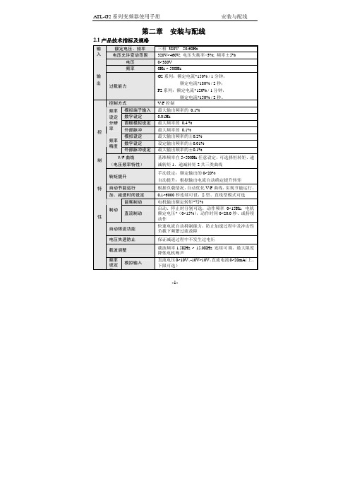
-1-第二章 安装与配线2.1产品技术指标及规格额定电压、频率 三相 380V 50/60Hz输入电压允许变动范围320V~460V; 电压失衡率<3%; 频率±5% 电压 0~380V 频率0Hz ~ 500Hz输 出过载能力G2系列:额定电流*150% / 1分钟,额定电流*180% / 2秒;P2系列:额定电流*120% / 1分钟,额定电流*150% / 2秒。
控制方式 V/F 控制模拟端子输入最大输出频率的 0.1% 数字设定 0.01Hz面板模拟设定最大频率的 0.4 % 频率 设定 分辨 率外部脉冲最大频率的 0.1% 模拟设定最大输出频率的±0.2% 数字设定设定输出频率的±0.01% 频率精度外部脉冲设定最大输出频率的±0.1%V/F 曲线 (电压频率特性) 基准频率在5~500Hz 任意设定,可选择恒转矩、递减转矩1、递减转矩2共三类曲线 转矩提升手动设定:额定输出的0~20%自动提升:根据输出电流自动确定提升转矩 自动节能运行 根据负载情况,自动优化V/F 曲线,实现节能运行。
加、减速时间设定0.1~6000秒连续可设,S 型、直线型模式可选 能耗制动 电机输出额定转矩*75%制动 直流制动启动、停止时分别可选,动作频率0~15Hz ,电机额定电压*(0~15%),动作时间0~20.0秒、或持续动作自动限流功能 快速电流自动抑制能力,防止加速过程中及冲击性负载下频繁过流故障 电压失速防止保证减速过程中不发生过电压载波调整 载波频率1.5KHz ~ 15.0KHz 连续可调,最大限度降低电机噪声控 制 特 性频率设定 信模拟输入直流电压0~10V 、-10V~10V ,直流电流0~20mA (上、下限可选)数字设定 使用操作面板脉冲输入 0~50.000KHz (上、下限可选)启动信号 正转、反转、启动信号自保持(三线控制)可选定时器、计数器 内置定时器、计数器各一个,方便系统集成多段速控制功能/摆频运行 最多7段可编程多段速控制,每段速度的运行方向、运行时间分别可设。
ATL封装手册
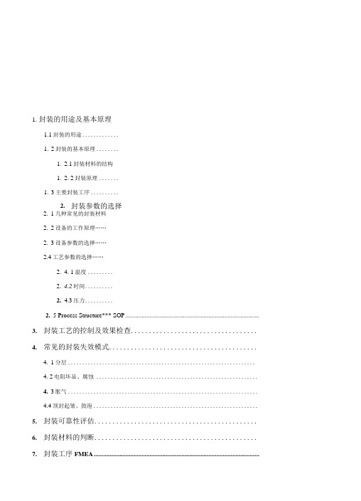
1.封装的用途及基本原理1.1封装的用途.............1.2封装的基本原理........1.2.1封装材料的结构1.2. 2封装原理.......1.3主要封装工序..........2.封装参数的选择2.1几种常见的封装材料2.2设备的工作原理……2.3设备参数的选择……2.4工艺参数的选择……2.4. 1温度.........2.4.2时间..........2.4.3压力..........2.5 Process Structure*** SOP ....................................................................................3.封装工艺的控制及效果检查...................................4.常见的封装失效模式.........................................4.1分层..................................................................4. 2电阻坏品、腐蚀 .........................................................4.3胀气...................................................................4.4顶封起皱、鼓泡..........................................................5.封装可靠性评估.............................................6.封装材料的判断.............................................7.封装工序FMEA ........................................................................................................故障6:真空度不够产生原因:(1)总的真空管路系统真空度不够(2)拆装封腔过程中没有装配好或是密封硅胶损坏而导致密封不良(3)真空电磁阀损坏或电磁阀内部电解液过多导致堵塞解决方法:(1)检查管路系统的真空度,确认系统问题后及时找厂房维修(2)重新装配封腔,更换密封硅胶(3)更换新的电磁阀或拆下电磁阀后清洗电磁阀内腔故障7:不抽真空产生原因:(1)真空电磁阀的电感线圈损坏导致电磁阀没有动作(2)上压腔的气缸动作传感器损坏或没有感应到而导致电磁阀没有指令信号(3)真空表的设置错误导致信号终止解决方法:(1)更换电磁阀的电感线圈(2)更换传感器或重新调整传感器的位置(3)重新校正真空表的设置2.3设备参数的选择封头的选择封头有两种,一种是用于Top sealing的顶封封头,一种是用于Side sealing和Degassing 封装的侧封封头。
安柏 AT6830 绝缘电阻测试仪 使用手册说明书

;AT6830用户手册@Instrumets常州安柏精密仪器有限公司江苏省常州市天宁区兰陵荡南工业园5楼[213014]电话:*************/89966117/89966227/400-600-1217传真:*************销售服务电子邮件: *****************技术支持电子邮件: ****************©2005-2009 Applent Instruments, Inc.当你发现有以下不正常情形发生,请立即终止操作并断开电源线。
立刻与安柏科技销售部联系维修。
否则将会引起火灾或对操作者有潜在的触电危险。
●仪器操作异常。
●操作中仪器产生反常噪音、异味、烟或闪光。
●操作过程中,仪器产生高温或电击。
●电源线、电源开关或电源插座损坏。
●杂质或液体流入仪器。
为避免可能的电击和人身安全,请遵循以下指南进行操作。
免责声明声明:!, $, #,标志和文字是常州安柏精密仪器有限公司已经或正在申请的商标。
有限担保和责任范围 3 AT6830 绝缘电阻测试仪User’s Manual简体中文Simplified ChineseRev.A@Instruments©2009 Applent Instruments, Inc.常州安柏精密仪器有限公司(以下简称Applent)保证您购买的每一台AT6830在质量和计量上都是完全合格的。
此项保证不包括保险丝以及因疏忽、误用、污染、意外或非正常状况使用造成的损坏。
本项保证仅适用于原购买者,并且不可转让。
自发货之日起,Applent提供玖拾(90)天保换和叁年免费保修,此保证也包括VFD或LCD。
玖拾天保换期内由于使用者操作不当引起的损坏,保换条款终止。
贰年包修期内由于使用者操作不当而引起仪器损坏,维修费用由用户承担。
贰年后直到仪表终生,Applent将以收费方式提供维修。
对于VFD或LCD的更换,其费用以当前成本价格收取。
ATL 服务程序

1. 新建项目。
1-1. 启动Visual Studio 2008。
选择File -> New -> Project...。
1-2. 在New Project 对话框中,选择Visual C++ 中的ATL Project 模板,写入项目名称:ShowjiSvc,点OK。
1-3. 在打开的ATL Project Wizard - ShowjiSvc 中,点Application Settings,选择Server type 为Service(EXE),点Finish。
2. 安装、卸载服务。
2-1. 编译项目。
2-2. 打开命令提示符,切换到编译后的目录,执行以下命令安装服务:ShowjiSvc /Service2-3. 打开服务管理,能找到一个名为ShowjiSvc 的服务,启动类型是Manual。
可以启动服务、停止服务。
2-4. 停止服务,然后用以下命令卸载服务:ShowjiSvc /UnRegServer3. 修改服务的配置。
3-1. 修改服务名称:在Resource View 中打开String Table,修改IDS_SERVICENAME 的Caption 为服务的名称:Showji Mobile Service。
3-2. 修改服务的描述:打开ShowjiSvc.cpp 文件,在CShowjiSvcModule 的声明中增加以下函数声明:HRESULT RegisterAppId(bool bService);再增加此函数的定义:HRESULT CShowjiSvcModule::RegisterAppId(bool bService = false) throw(){HRESULT hr = S_OK;BOOL res = __super::RegisterAppId(bService);if (bService){if (IsInstalled()){SC_HANDLE hSCM = ::OpenSCManagerW(NULL, NULL, SERVICE_CHANGE_CONFIG);SC_HANDLE hService = NULL;if (hSCM == NULL)hr = AtlHresultFromLastError();else{hService = ::OpenService(hSCM, m_szServiceName, SERVICE_CHANGE_CONFIG);if (hService != NULL){::ChangeServiceConfig(hService, SERVICE_NO_CHANGE,SERVICE_AUTO_START,// 修改服务为自动启动NULL, NULL, NULL, NULL, NULL, NULL, NULL,m_szServiceName); // 通过修改资源IDS_SERVICENAME 修改服务的显示名字SERVICE_DESCRIPTION Description;TCHAR szDescription[1024];ZeroMemory(szDescription, 1024);ZeroMemory(&Description, sizeof(SERVICE_DESCRIPTION));lstrcpy(szDescription, _T("示例服务,by yangwei@"));Description.lpDescription = szDescription;::ChangeServiceConfig2(hService, SERVICE_CONFIG_DESCRIPTION,&Description);::CloseServiceHandle(hService);}elsehr = AtlHresultFromLastError();::CloseServiceHandle(hSCM);}}}return hr;}3-3. 测试修改后的服务。
OASIS 测量手册说明书

INSTRUCTION MANUALThe OASIS measures the core domains of subjective illness awareness in obesity, including general illness awareness, accurate symptom attribution, awareness of need for treatment, and awareness of negative consequences attributable to being overweight or having obesity.OASIS is the first validated, obesity-specific instrument that reliably and comprehensively measures subjective obesity awareness. Item development was guided by existing theoretical models and previously validated scales of illness awareness in other conditions, including neuropsychiatric disorders. OASIS shows good psychometric properties with strong internal consistency, convergent and discriminant validity, and test-retest reliability. The 8-item scale can be completed in less than 2 minutes.Each scale item consists of a 10-point Likert scale to capture small differences in awareness. OASIS can be used clinically and for research, including epidemiological studies and prospective treatment trials to investigate the extent to which subjective obesity awareness contributes to medication adherence and clinical outcomes; or neuroimaging and neurophysiological studies to identify the neural correlates of obesity awareness.The OASIS is available for download at . Please see legal terms of use.Below you will find instructions on how to use and score OASIS.Prior to administering OASIS, the participant or the clinician is to enter data on the most recent weight and height, calculated BMI, blood pressure, fasting glucose, and HbA1c level on the top of page 1. Note that this clinical data is not required for the completion of OASIS. BMI provides an objective measure to support the participant being overweight or having obesity. Similarly, blood pressure and glucose levels provide markers of the status of other metabolic factors.The scale consists of the following:1)ASSESSMENT OF SYMPTOM ATTRIBUTION(Page 1)2)ASSESSMENT OF GENERAL ILLNESS AWARENESS, AWARENESS OF NEED FORTREATMENT, AND AWARENESS OF NEGATIVE CONSEQUENCES (Page 2)3)SCORING SHEETThe participant should read all content of the OASIS in order to accurately report his/her understanding of his/her illness, symptoms, need for treatment and negative consequences of the illness.- - -ASSESSMENT OF SYMPTOM ATTRIBUTION(Page 1)The ASSESSMENT OF SYMPTOM ATTRIBUTION (page 1) consists of an introductory statement indicating that the participant should report on his/her own beliefs about his/her weight and NOT on what others may wish him/her to believe.Following the introductory statement, the participant is to report on current health-related symptoms in a categorical fashion, i.e. by marking ‘Yes’ or ‘No’ beside the listed symptoms. The aim is for the participant to indicate any health-related symptoms he/she has.If the participant reported ‘No’ to all of the listed symptoms, he/she is instructed to proceed to the next page.If the participant said ‘Yes’ to any of the listed symptoms, he/she is instructed to indicate the extent to which he/she agrees or disagrees at the present moment with the proceeding statement by circling the appropriate number, keeping in mind his/her health-related experience.Item 1 specifically assesses the participant’s Symptom Attribution, i.e. the degree to which the participant is able or unable at the present moment to attribute his/her health-related symptoms (current or past) to his/her weight.In some cases, a participant may not report any health-related symptoms, which may leave the participant unable to rate item 1. If this is the case, the participant should leave item 1 unrated as though it were ‘Not applicable’, which will allow for proper scoring of OASIS (See SCORING SHEET).ASSESSMENT OF GENERAL ILLNESS AWARENESS, AWARENESS OF NEED FOR TREATMENT, AND AWARENESS OF NEGATIVE CONSEQUENCES (Page 2)The ASSESSMENT OF GENERAL ILLNESS AWARENESS, AWARENESS OF NEED FOR TREATMENT, AND AWARENESS OF NEGATIVE CONSEQUENCES (Page 2) consists of an introductory statement indicating that the participant should indicate the extent to which he/she agrees or disagrees at the present moment with the statements from item 2 to item 8.Item 2, item 4, and item 7 specifically assesses the participant’s General Illness Awareness, i.e. the participant’s awareness that he/she is overweight or obese (i.e. Body Mass Index greater than 25 = overweight; Body Mass Index greater than 30 = obese).Item 3, item 5, and item 8 specifically assess the participant’s Awareness of Need for Treatment, i.e. the participant’s awareness of the need for lifestyle modifications (physical activity and dietary changes) or treatment.Item 6 specifically assesses the participant’s Awareness of Negative Consequences attributable to the obesity, including high cholesterol, hypertension, diabetes, heart disease, depression.SCORING SHEETThe SCORING SHEET allows for the proper scoring of the OASIS’ Awareness Categories and Average Total Score. Step-by-step instructions are provided below.1)Calculate each Awareness Category score by copying the rating from each item to thecorresponding blank space on the SCORING SHEET. For example, if the rating for Item1 of is ‘8’ Moderately Agree then ‘8’ should be copied to the blank space beside Q1 ofthe Symptom Attribution category of the SCORING SHEET.*Note that the score for the Symptom Attribution category should be left blank if item1 was not rated.82)The calculations in the Calculation column of the SCORING SHEET should beperformed to generate the Awareness Category scores in the Score column.3)Once calculated, the Awareness Category Scores should be summed to determine theSubtotal.4)The OASIS Average Total Score is calculated by dividing the Subtotal by the number ofAwareness Categories for which a score could be determined. The OASIS Average Total Score should be divided by four if all categories were measured. The OASIS Average Total Score should be divided by three if no score was reported for Symptom Attribution.。
EATON FlexiTech SU ATL 自动测试自包容燈说明书

FlexiTech SU AT• Self-contained luminaire with Automatic Test for reduced inspection effort• Innovative precise micro lenses guide light efficiently along the escape route while thanks to the large light output area the glare is significantly reduced, especially suitable in applications like night light• Universal light distribution equally suitable for escape route and open area lighting for mounting heights from 2.5 to 8m (420 lm version, 1hour duration)• Up to 420 lm in a very compact luminaire• Robust construction IK07 for reliable operation even in difficult environments • Available with protection degrees IP43 and IP66• Light output selectable in two steps in mains operation (eg. theater: 10 lm, supermarket: 100 lm) and additional setting (30%, 70%, 100%)• Selectable operating time (1/2/3/8h operation)• Selectable operation mode (Maintained or Non-Maintained) via switch input• F ast installation and effortless wiring thanks to: cable entries in rubber, large space for cabling, screwless terminal blocks, integrated spirit level and first fixed base plate to snap on the housing without any tool•T ransparent base plate with honeycomb footprint for easy replacement of existing products (IP4x use only)• Low eco footprint thanks to its eco design, low consumption and Lithium battery • Simple fault analysis and status display via bicolor LED, testing button (magnet)• Complete range of accessories available (recessed kit, recessed box for plaster and brick wall, wire guard)• Coloured accessories available on demandLuminous flux ΦE /ΦNat end of rated operating time100% @ 1h, 54% @ 2h, 33% @ 3h, 12% @ 8hIllumination in mains mode 10 or 100lm setting via switch,and possible additional setting via magnet (30%, 70%, 100%) Operation Maintained / Non-Maintained (via switch input)Testing system Automatic Test in compliance with EN 62034HousingType of mounting Material Colour Surface-mounting Polycarbonate White RAL9003Degree of protection IP43 or IP66 / IK07TerminalsScrewless terminals for flexible and rigid wires From 0,5 to 2,5 mm²Connection voltage220 - 240 V AC, 50/60 HzPermissible ambient temperature 5°C to 45°C, 0°C to 45°C in maintained mode Battery LiFePO4Light sourceLED, 6 500 K, CRI ≥70, Lifespan 100 000h Dimensions 231 x 86 x 34 mm Insulation ClassIISSmallFlexiTech SU - SmallOrdering detailsOrder codeI PI K1h2h3h8hl m i n m a i n sO p e r a t i o nN M W /V AM W / V A B a t t e r y W e i g h t (k g )FT1SU400ATL1843074202251405010 / 100MNM 0,3W / 1 VA 2W / 5 VA FT -BAT30,38FT1SU400ATL18IP66074202251405010 / 100MNM 0,3W / 1 VA2W / 5 VAFT -BAT30,38Consumptionlm in emergency at the selected durationDimensions (mm)2318634Accessories Black matRAL9005Dark GreyRAL7015Silver glossRAL9007FT1-RK Recess Kit compatible with FlexiTech FT1SU FT1-RK-B FT1-RK-DG FT1-RK-S Metal cover compatible with FlexiTech FT1SU FT1EWSU-MC-B FT1EWSU-MC-DG FT1EWSU-MC-SFT2-WG Wire Guard, compatible with FlexiTech FT1SUFT1-RB Recess box / plaster & brick for FlexiTech FT1SUFT1SU-RP Renovation Plate for FlexiTech FT1SUEMN Eaton Magnet for confi guration and testsFT-BAT3Battery LiFePO4, 3,2V / 3000mAh3,522,5 (4,2)8,4 (11,3)3,0 (5,3)10,6 (13,9)41,62,2 (4,1)8,2 (11,7)2,3 (5,3)10,7 (14,4)4,51,21,7 (3,8)7,6 (11,9)1,8 (5,2)9,8 (14,8)510,6 (3,5)7,0 (11,9)0,6 (4,1)8,1 (15,0)Open area illuminationOpen area illuminationMounting height [m]2,51,5 (2,6)5,2 (6,8)1,5 (2,6)6,0 (7,5)2,81,4 (2,5)5,0 (7,0)1,4 (2,5)5,8 (7,9)31,3 (2,2)4,8 (7,2)1,3 (2,2)5,6 (8,3)Mounting height [m]2,53,0 (3,8)7,6 (9,4)3,0 (3,8)8,3 (10,1)2,83,0 (3,9)7,9 (9,9)3,0 (3,9)8,7 (10,6)3,03,0 (3,9)8,0 (10,2)3,0 (3,9)8,9 (11,1)3,52,7 (4,0)8,5 (10,7)2,7 (4,0)9,6 (11,8)4,02,3 (4,1)8,7 (11,1)2,2 (4,1)10,2 (12,3)4,52,1 (4,0)8,4 (11,5)2,1 (4,0)9,8 (12,9)5,01,9 (3,4)8,0 (12,0)1,9 (3,4)9,3 (13,9)3,53,33,7 (5,2)10,4 (13,4)4,8 (6,4)12,8 (16,3)42,53,4 (5,3)10,6 (13,9)4,7 (6,6)13,2 (17,1)4,523,1 (5,4)10,7 (14,4)3,6 (6,7)13,5 (17,7)51,62,8 (5,2)10,5 (14,8)3,0 (6,8)13,5 (18,2)5,52,4 (5,0)9,9 (15,0)2,5 (6,7)12,7 (18,6)61,7 (4,7)9,3 (15,1)1,7 (6,3)11,8 (18,9)Open area illuminationMounting height [m]2,53,5 (4,4)8,9 (10,7)3,5 (4,4)9,6 (11,4)2,83,6 (4,5)9,2 (11,3)3,6 (4,5)10,1 (12,1)33,7 (4,6)9,4 (11,6)3,7 (4,6)10,3 (12,5)3,53,7 (4,8)9,9 (12,4)3,7 (4,8)11,0 (13,4)43,6 (4,9)10,3 (13,1)3,6 (4,9)11,6 (14,3)4,53,1 (5,0)10,8 (13,6)3,1 (5,0)12,5 (14,9)52,8 (5,0)10,9 (14,0)2,8 (5,0)12,9 (15,6)5,52,6 (5,0)10,7 (14,4)2,6 (5,0)12,7 (16,1)62,4 (4,8)10,4 (14,8)2,4 (4,8)12,3 (16,7)3,56,35,1 (6,5)13,1 (16,2)6,3 (8,0)15,9 (19,5)44,85,2 (6,8)13,6 (17,2)6,4 (8,4)16,7 (20,7)4,53,85,1 (7,0)14,0 (17,9)6,5 (8,6)17,3 (21,7)535,0 (7,2)14,4 (18,5)6,5 (8,9)17,7 (22,6)5,52,54,7 (7,3)14,5 (19,1)6,4 (9,0)18,1 (23,4)62,14,4 (7,3)14,6 (19,5)5,6 (9,2)18,3 (24,0)6,51,84,1 (7,2)14,5 (19,9)4,4 (9,3)18,5 (24,6)71,53,7 (7,1)14,2 (20,3)3,9 (9,2)18,3 (25,0)7,51,33,3 (6,8)13,6 (20,5)3,4 (9,1)17,3 (25,4)81,22,6 (6,5)12,9 (20,6)2,7 (8,8)16,5 (25,7)8,511,5 (6,2)12,4 (20,6)1,6 (7,8)15,3 (25,9)Open area illuminationMounting height[m]2,53,8 (4,6)10,6 (12,7)4,1 (4,9)12,0 (14,2)2,84,4 (5,4)11,1 (13,3)4,4 (5,4)11,9 (14,1)34,5 (5,5)11,4 (13,8)4,5 (5,5)12,3 (14,7)3,54,7 (5,9)12,2 (14,7)4,7 (5,9)13,2 (15,7)44,8 (6,1)12,8 (15,7)4,8 (6,1)14,0 (16,8)4,54,9 (6,3)13,3 (16,5)4,9 (6,3)14,5 (17,8)54,9 (6,4)13,7 (17,3)4,9 (6,4)15,2 (18,8)5,54,8 (6,6)14,1 (17,8)4,8 (6,6)15,8 (19,5)64,4 (6,7)14,5 (18,3)4,4 (6,7)16,7 (20,1)6,53,8 (6,7)14,9 (18,8)3,8 (6,7)17,5 (20,8)73,6 (6,7)14,9 (19,3)3,6 (6,7)17,7 (21,4)7,53,4 (6,6)14,6 (19,7)3,4 (6,6)17,4 (22,1)83,2 (6,4)14,3 (20,1)3,2 (6,4)16,9 (22,7)8,53,0 (5,9)13,9 (20,6)3,0 (5,9)16,3 (23,6)91,9 (4,8)14,3 (21,3)0,5 (3,3)17,1 (25,1)。
ATL控件的Web发布方法(内附zxca使用说明)

connection settings(网络连接设置),点击第一个 settings,如果其中的 web server(HTTP)选项没有被勾选,一定要将其选上。 8,进行链接测试。在本机和其他机器上登陆:http://本机 IP 地址/default.htm 如 果登陆成功,则证明服务器搭建成功,可以进行下一步 ATL 控件工程创建。
图 1.1 4、安装成功后,系统会自动在系统盘新建网站目录,默认目录为: C:\Inetpub\wwwroot 5、打开控制面板-管理工具-Internet 信息服务,如图 1.2:
- 4 - / 33
NEWNEU Robot Lab,Northeastern University,China
图 1.2 6、在默认网站(Default Web Site)上点击右键-选择属性:在 Web Site 选项卡中 出现的 Description 中显示 Default Web Site,表明配置成功,如图 1.3。
NEWNEU Robot Lab,Northeastern University,China { public: CmyActiveX () { } DECLARE_REGISTRY_RESOURCEID(IDR_EDUTAIMENTCONSOLE) BEGIN_COM_MAP(CmyActiveX) // 实现安全接口 COM_INTERFACE_ENTRY(IObjectSafety) COM_INTERFACE_ENTRY(ImyActiveX) END_COM_MAP() // 加入到 CATID_SafeForScripting 和 CATID_SafeForInitializing COM 分组 BEGIN_CATEGORY_MAP(CmyActiveX) IMPLEMENTED_CATEGORY(CATID_SafeForScripting) IMPLEMENTED_CATEGORY(CATID_SafeForInitializing) END_CATEGORY_MAP() DECLARE_PROTECT_FINAL_CONSTRUCT() HRESULT FinalConstruct() { return S_OK; } void FinalRelease() { } public: // 加入这 2 个方法 STDMETHOD(GetInterfaceSafetyOptions)(REFIID riid,DWORD *pdwSupportedOptions,D WORD *pdwEnabledOptions); STDMETHOD(SetInterfaceSafetyOptions)(REFIID riid,DWORD dwOptionSetMask,DWOR D dwEnabledOptions); }; OBJECT_ENTRY_AUTO(__uuidof(myActiveX), CEmyActiveX) ------------------------------------------------------------------
QSW7602 ATL procedure
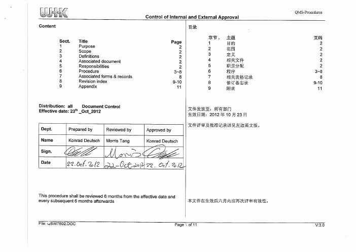
2. SCOPE:
This procedure shall apply to all products in WIK.
2. 适用范围 本程序适用于 WIK 所有产品。 3. 定义 ATL: 安规测试实验室 D&D: 产品设计研发部 DFMEA: 设计失效模式影响分析 EMC: 电磁兼容 测试 EMF: 电磁场效应 LVD: 低压指令 PE: 产品工程部 PFMEA: 过程失效模式影响分析 QA: 质量保证部 QE: 质量工程部 TDS: 测试数据表
h) QF-ATL-021 产品待机和关闭电源的情况功率测试报 告.根据 ERP 指令来对产品待机和关闭模式下消耗功率 的进行测试. i) QF-ATL-031 寿命测试报告:用于模拟电器的正常使用情 形下的测试.
V:3.0
File: QSW7602.DOC
QMS-Procedures
Control of Internal and External Approval
QMS-Procedures
Control of Internal and External Approval 1. PURPOSE:
The purpose of this procedure is to control the fulfillment of legal as well as WIK’s safety, EMC and performance requirements of electrical products. 1. 目的 制定本程序以控制产品安全, 电磁兼容及电气测试过程。
File: QSW7602.DOC Page 3 of 11
V:3.0
QMS-Procedures
Control of Internal and External Approval
新能源科技(ATL)2015届校园招聘需求

公司介绍新能源科技有限公司(Amperex Technology Limited,简称ATL)成立于1999年,全球研发和运营中心位于风景秀美的海滨城市福建宁德,分支机构分布于北京、上海、香港、台北、东莞、西宁、德国慕尼黑和美国圣何塞等地。
ATL是全球知名的锂离子电池制造商,致力于开发、生产和销售先进的可充电锂离子电池、电池组和管理系统,在专业锂离子电池制造商中其技术、产能与销量均处于全球领先地位。
ATL产品主要应用于消费电子领域(智能手机、平板电脑、便携式电脑等)、动力电池领域(纯电动汽车、混合动力汽车等)和储能领域(清洁能源、电信设施、移动储能等)。
ATL消费电子产品主要供给全球一线品牌,动力电池产品与世界顶级整车厂建立了长期战略合作伙伴关系,储能领域已参与多项国内可再生能源重点工程建设并获得主管机构的高度认可。
ATL全球员工总数超过两万人,目前年产值近百亿,并将持续保持高速增长。
ATL拥有国际化的高管团队与核心技术团队,团队主要成员来自欧美、大陆、港台等国家和地区全球知名电子和汽车企业,具备全球视野和丰富的管理、技术经验。
技术与创新是ATL的成功之道,目前公司拥有100余名博士,700余名硕士,并与国内外多所知名高校、科研院所建立了深入的合作关系。
此外,ATL在2010年获国家教育部批准设立企业博士后工作站,在2013年获国家“十二五”计划“新能源汽车产业技术创新工程重点扶持企业”称号。
ATL企业文化以“快速学习”为核心,着力打造“练好基本功,发挥想象力”的工程师文化,致力于为全球各地加盟的优秀人才提供“与企业共赢”的“无天花板”职业发展平台。
在ATL,员工可以通过与世界顶级专家和顶级客户合作、全球岗位轮换和系统化的培训体系等多种渠道获得快速学习和成长的机会。
同时,ATL秉承“以结果为导向、以贡献定回报”的人才价值观,着力吸引和培养“以人为本、志存高远、勇于任事、独立思考、快速行动”的青年才俊,帮助他们快速成长为公司下一步发展的中坚力量,并为他们提供丰厚的物质回报。
VIAVI ALT-8000 8015 电磁波基于的可携带飞行线路测试设备操作手册说明书

Test NoteRadio Altimeter Test Procedure Using theVIAVI ALT-8000/8015The VIAVI ALT-8000/8015 RF-Based Portable Radio Altimeter Flight Line Test Set allows replication of in-flight conditions by simulating altitudes, including climb/descend profiles, to verify your installed system and isolate a bad component.This document provides the basic instructions to test an installed system. With little editing, it can be easily adapted to your aircraft platform for formal procedure development.ContentsALT-8000/8015 Test Setup ……………………………………………………………………………………. Page 1 Altitude Simulation Test via Direct-Connect ……………………………………………………….………… Page 5 Altitude Simulation Test via Coupler …………...…………………………………………………….………. Page 7 Profile Test – Direct or Coupler…...…………………………………………………………………………… Page 9 Radio Altimeter Sensitivity Test – Direct or Coupler …….……….………………………………….……. Page 13 ALT-8000/8015 Test SetupRadio altimeter: Ensure the aircraft or bench test fixture is energized, however the radio altimeter should be in the OFF condition.ALT-8000/8015:1. Press the Power On button on the front of the ALT-8000 to power on the test set. See Fig. 1-1.Figure 1-1 Power On Button2. On the launch bar, press the Test Setup function key. See Figure 1-2.Figure 1-2 Launch Bar3. Locate the two 20 ft cables (P/N 88511 and 89527), the two 4 ft cables (P/N 91253 and 91255) orthe 100 ft cable set (P/N 88500), whichever will be used.NOTE: The 20 ft cables will be referenced in this procedure.4. Connect the cable with the yellow ends (P/N 88511) to the UUT:RX (Yellow) connector on the toppanel of the ALT-8000/8015. See Figure 1-3.5. Connect the cable with the red ends (P/N 89527) to the UUT:TX (Red) connector of the ALT-8000/8015. See Figure 1-3.Figure 1-3 ALT-8000/8015 Top Panel6. Connect the other ends of the 20 ft cables together, using one of the supplied TNC to TNC Adapters(P/N 38353).NOTE: For the Delay Calibration, the 20 dB attenuators should NOT be installed on the ALT-8000/8015.7. On the Test Setup screen, press the Delay Calibration button. See Figure 1-4.Figure 1-4 Test Setup Screen8. On the Delay Calibration screen, press the Start button to start the delay calibration. See Figure 1-5.NOTE: The calibration process is automatic. When delay calibration is complete, the Test Setup screen is displayed.Figure 1-5 Delay Calibration Screen9. Remove the TNC to TNC Adapter from between the TX and RX cables.10. Set UUT Settings – UUT Detect Mode to Auto. See Figure 1-4.11. Set RF Settings – Level Mode to Auto. See Figure 1-4.12. On the Test Setup screen, press the Loss button to go to the Loss setup page. See Figures 1-4and 1-6.Figure 1-6 Loss Setup Screen13. Locate the cable loss value listed on the cable connected to the UUT:TX port (Red) and enter thisvalue as Cable Loss – UUT:TX Cable Loss (Red). See Figure 1-6.14. Locate the cable loss value listed on the cable connected to the UUT:RX port (Yellow) and enter thisvalue as Cable Loss – UUT:RX Cable Loss (Yellow) See Figure 1-6.15. For coupler testing, enter 20 dB as Ext. Attenuation – UUT:RX Attenuation (Yellow) and for directconnect testing, enter 40 dB as Ext. Attenuation – UUT:RX Attenuation (Yellow). See Figure 1-6.NOTE: 20 dB attenuators are only required for pulse type radio altimeters. They are not used for FMCW and FMCW-CDF type radio altimeters.16. Locate the coupler with the red UUT:TX label and then locate the Loss Value label on the coupler.Enter the Coupler Loss Value as Coupler Loss – UUT:TX Coupler Loss (Red). See Figure 1-6. 17. Locate the coupler with the yellow UUT:RX label and then locate the Loss Value label on thecoupler. Enter the Coupler Loss Value as Coupler Loss – UUT:RX Coupler Loss (Yellow). See Figure 1-6.Altitude Simulation Test via Direct-Connect1. Perform the ALT-8000/8015 Test Setup instructions beginning on page 1.2. Ensure that two of the 20 dB TNC attenuators are connected to the UUT:RX Port (Yellow) of theALT-8000/8015. Connect one 20 dB attenuator directly to the ALT-8000/8015 and then connect the second 20 dB attenuator directly to the first one. Then connect the coax to these attenuators.NOTE: 20 dB attenuators are only required for pulse type radio altimeters. They are not used forFMCW and FMCW-CDF type radio altimeters.3. Connect the red coaxial cable to the TX port of the radio altimeter being tested. Connect the yellowcoax to the RX port of the radio altimeter being tested.4. Apply power to the radio altimeter being tested.5. Set RF Settings – Connection Type to Direct. See Figure 2-1.Figure 2-1 Test Setup - Direct6. Touch the gray vertical bar on the left side of the display to display the launch bar.7. On the launch bar, press the Simulation function key. See Figure 1-2 and 2-2.Figure 2-2 Simulation Screen8. Ensure Control – Simulation is set to Manual. See Figure 2-2.9. Set Control – Altitude to 100 ft. See Figure 2-2.10. Press the Run button to start the altitude simulation. See Figure 2-2.11. Ensure that an RF value is displayed in the UUT Parameters – Power (at UUT) window. If no poweris displayed, check your connections and power to the UUT. See Figure 2-3.12. Verify that the UUT Parameters are all within the desired range.13. Verify that the display on the RADIO ALTIMETER displays approximately 100 ft.NOTE: The Delay Settings – Altitude Offset setting may be adjusted to make the display read exactly 100 ft. See Figure 2-1.14. Press the Control - Altitude Pause button to change the simulated altitude. See Figure 2-3.15. Set Control - Current Altitude to desired test altitude (i.e. 500 ft, 1000 ft, 1500 ft.) up to maximumaltitude capable for your radio.16. Verify that the UUT Parameters are all within the desired range.NOTE: Link margin is only displayed for pulse type radio altimeters.17. Verify that the display on the RADIO ALTIMETER displays approximately the same as the ControlCurrent Altitude setting.18. Press the Stop button to stop the altitude simulation. See Figure 2-3.Figure 2-3 Simulation ScreenAltitude Simulation Test via Coupler1. Perform the ALT-8000/8015 Test Setup instructions beginning on page 1.2. Ensure that one of the 20 dB TNC attenuators is connected to the UUT:RX Port (Yellow) of the ALT-8000/8015. Connect the 20 dB attenuator directly to the ALT-8000/8015 and then connect the coax to the attenuator.NOTE: 20 dB attenuators are only required for pulse type radio altimeters. They are not used forFMCW and FMCW-CDF type radio altimeters.3. Locate the UUT:RX (Yellow) coupler and connect it to the UUT:RX (Yellow) cable.4. Adjust the support poles to a length that will allow the compression poles to press the couplers intothe aircraft just tight enough to hold the couplers in place.5. Place the UUT:TX (Red) coupler over the TX antenna, with the arrow pointing toward the front of theaircraft.NOTE: Some aircraft may have the antennas oriented toward each other and not toward the front of the aircraft. To determine the orientation, rotate the coupler 90 degrees at a time while watching the output power reading on the ALT-8000/8015. The highest power measurement indicates the correct placement of the coupler and the orientation of the antenna. Leave the coupler in the position that produced the highest power measurement.6. Place the UUT:RX (Yellow) coupler over the RX antenna, with the arrow pointing toward the front ofthe aircraft.NOTE: If the TX antenna coupler is oriented toward the front of the aircraft, then orient the RXcoupler toward the front of the aircraft. If the TX antenna coupler is pointed toward the RX antenna, then orient the RX coupler toward the TX antenna coupler.7. Touch the gray vertical bar on the left side of the display to display the launch bar.8. On the launch bar, press the Simulation function key. See Figures 1-2 and 2-2.9. Ensure Control – Simulation is set to Manual. See Figure 2-2.10. Set Control – Altitude to 100 ft. See Figure 2-2.11. Press the Run button to start the altitude simulation. See Figure 2-2.12. Ensure that an RF value is displayed in the UUT Parameters – Power (at UUT) window. If no poweris displayed, check your connections, coupler positioning, and power to the UUT. See Figure 2-3.13. Verify that the UUT Parameters are all within the desired range.14. Verify that the display on the RADIO ALTIMETER displays approximately 100 ft.NOTE: The Delay Settings – Altitude Offset setting may be adjusted to make the display read exactly 100 ft. See Figure 2-1.15. Press the Control - Altitude Pause button to change the simulated altitude. See Figure 2-3.16. Set Control - Current Altitude to desired test altitude (i.e. 500 ft, 1000 ft, 1500 ft.) up to maximumaltitude capable for your radio.17. Verify that the UUT Parameters are all within the desired range.18. Verify that the display on the RADIO ALTIMETER displays approximately the same as the Control–Current Altitude setting.19. Press the Stop button to stop the altitude simulation. See Figure 2-3.Profile Test – Direct or Coupler1. Perform the ALT-8000/8015 Test Setup instructions beginning on page 1.2. Perform one of the two following steps depending upon whether you are direct-connecting or using acoupler.- Direct-Connect: Locate two of the 20 dB TNC attenuators and connect both to the UUT:RX Port (Yellow) of the ALT-8000/8015. Connect one 20 dB attenuator directly to the ALT-8000/8015and then connect the second 20 dB attenuator directly to the first one. Then connect the coax tothese attenuators. Ensure that 40 dB is entered as the Test Setup – Loss – Ext. Attenuation –UUT:RX Ext Attenuation value.- Coupler: Locate one of the 20 dB TNC attenuators and connect it to the UUT:RX Port (Yellow) of the ALT-8000/8015. Connect the 20 dB attenuator directly to the ALT-8000/8015 and thenconnect the coax to the attenuator. Ensure that 20 dB is entered as the Test Setup – Loss –Ext. Attenuation – UUT:RX Ext Attenuation value.3. Set RF Port Settings – Connection Type to Direct or Coupler. See Figure 2-1.4. Touch the gray vertical bar on the left side of the display to display the launch bar.5. On the launch bar, press the Profile Setup function key. See Figures 1-2 and 4-1.Figure 4-1 Profile Setup Screen6. To add a leg to the profile, press the Add button and the Add Leg pop-up window will be displayed.See Figures 4-1 and 4-2.7. Enter a Start Altitude of 100 ft.8. Enter a Stop Altitude of 100 ft.9. Enter a Leg Duration of 30 s.10. Press the Enter button to add Leg 1 to the profile. See Figures 4-2 and 4-3.Figure 4-2 Profile Setup11. Press the Add button and the Add Leg pop-up window will be displayed again. See Figures 4-1, 4-2and 4-3.12. Enter a Start Altitude of 100 ft.13. Enter a Stop Altitude of 500 ft.14. Enter an Altitude Rate of 1000 ft/min.15. Press the Enter button to add leg to the profile. See Figures 4-2 and 4-3.Figure 4-3 Complete Setup16. Press the Add button and the Add Leg pop-up window will be displayed. See Figures 4-1 and 4-2.17. Enter a Start Altitude of 500 ft.18. Enter a Stop Altitude of 500 ft.19. Enter a Leg Duration of 30 s.20. Press the Enter button to add leg to the profile. See Figures 4-2 and 4-3.21. Press the Add button and the Add Leg pop-up window will be displayed again. See Figures 4-1, 4-2and 4-3.22. Enter a Start Altitude of 500 ft.23. Enter a Stop Altitude of 1000 ft.24. Enter an Altitude Rate of 1000 ft/min.25. Press the Enter button to add leg to the profile. See Figures 4-2 and 4-3.26. Press the Add button and the Add Leg pop-up window will be displayed. See Figures 4-1 and 4-2.27. Enter a Start Altitude of 1000 ft.28. Enter a Stop Altitude of 1000 ft.29. Enter a Leg Durationof 30 s.30. Press the Enter button to add leg to the profile. See Figures 4-2 and 4-3.31. Press the Add button and the Add Leg pop-up window will be displayed again. See Figures 4-1, 4-2and 4-3.32. Enter a Start Altitude of 1000 ft.33. Enter a Stop Altitude of 1500 ft.34. Enter an Altitude Rate of 1000 ft/min.35. Press the Enter button to add leg to the profile. See Figures 4-2 and 4-3.36. Touch the gray vertical bar on the left side of the display to display the launch bar.37. On the launch bar, press the Simulation function key. See Figures 1-2 and 2-2.38. Set Control – Simulation to Profile. See Figure 4-4.39. Press the Run button to start the profile simulation. See Figure 4-4.Figure 4-4 Simulation – Profile Screen40. Verify that the UUT Parameters are all within the desired range. You will have 30 seconds to verifythe parameters.41. Verify that the displayed altitude on the RADIO ALTIMETER display tracks the altitude displayed inthe Control – Current Altitude window. See Figure 4-4.42. Press the Stop button to stop the profile simulation.Figure 5-1 Test Setup – RF Settings - ManualRadio Altimeter Sensitivity Test – Direct or Coupler1. Perform the ALT-8000/8015 Test Setup instructions beginning on page 1.2. Perform one of the two following steps depending upon whether you are Direct Connecting or usinga Coupler.- DIRECT CONNECT : Locate two of the 20 dB TNC attenuators and connect both to the UUT:RXPort (Yellow) of the ALT-8000/8015. Connect one 20 dB attenuator directly to the ALT-8000/8015 and then connect the second 20 dB attenuator directly to the first one. Then connect the coax to these attenuators. Ensure that 40 dB is entered as the Test Setup – Loss – Ext. Attenuation – UUT:RX Ext Attenuation value.-COUPLER : Locate one of the 20 dB TNC attenuators and connect it to the UUT:RX Port(Yellow) of the ALT-8000/8015. Connect the 20 dB attenuator. Ensure that 20 dB is entered as the Test Setup – Loss – Ext. Attenuation – UUT:RX Ext Attenuation value.3. Perform the 100 ft altitude setup steps from Step 2 (Direct Connect) or Step 3 (Coupler) above.4. Touch the gray vertical bar on the left side of the display to display the launch bar.5. On the launch bar, press the Test Setup function key. See Figure 1-2.6. Set RF Settings – Level Mode to Manual . See Figure 5-1.7. Touch the gray vertical bar on the left side of the display to display the launch bar.8.On the launch bar, press the Simulation function key. See Figure 1-2.9. Touch the Control – RF Level window to bring up the RF Level adjustment window.NOTE: You may enter the values manually; use the adjustment dial; or use the slide bar to change the RF Level. See Figure 5-2.Figure 5-2 Simulation – RX Sensitivity10. Adjust the RF level downward until the RADIO ALTIMETER display stops reporting the 100 ftaltitude.11. The RF level where the RADIO ALTIMETER stops reporting the correct altitude is the sensitivitylevel of the receiver.12. Press the Stop button to stop the profile simulation.Contact Us:+1 316 522 4981*******************************To reach the VIAVI office nearest you, visit /contact.© 2019 VIAVI Solutions Inc.Product specifications and descriptions in this document are subject to change without notice.February 22, 2019。
ATL-聚合物锂电池原理 - 副本

ATL聚合物锂离子电池资料来源:●工序来自ME●测试方法及数据来自TE●一些电池性能评估及计算来自CE●其它摘自国内外公开出版的有关书籍及文章目录第一章电化学系统与化学电源1.1 电化学反应系统1.2 各类化学电源简介1.3 电池的性能参数第二章聚合物锂离子电池及材料2.1 聚合物锂离子电池简介2.2 正极材料的结构和性能2.3 负极材料的结构和性能2.4 电解液2.5 锂离子电池用粘接剂2.6 聚合物锂离子电池用增塑剂2.7 隔离膜2.8 碳负极上的SEI膜第三章ATL聚合物锂离子电池的制造工序第四章聚合物锂离子电池实例---ATL413462D之性能4.1 活性物质的容量密度4.2 容量平衡4.3 ATL电芯413462D的构成与的性能第五章ATL聚合物锂离子电池性能检测5.1 充放电制式5.2 性能测试5.3 贮存测试5.4 机械性能试验5.5 安全性测试第一章电化学系统与化学电源1.1 电化学反应系统电化学反应包含电极与反应物质之间的电子交换过程。
虽然在普通化学反应中也有的有电子转移,但在电极成为电子交换的对象这一点上,电化学反应与普通化学反应不同。
为了进行电化学反应,还需要一些“装置”。
本节举例介绍电化学反应的特征、电化学体系的构成,以及电化学反应的装置。
氢气和氧气混合点火将发生爆炸性反应。
这是因为在生成水的同时放出大量的热的缘故。
其反应式如下:2H2+O2=2H2O 放热237.2J(H2O)-------------- (1.1)如果稍微仔细分析,反应过程可分成如下两步:2H2=4H++4e- -------------- (1.2)O2+4H++4e-=2H2O -------------- (1.3) 氢放出电子后变成质子,即氢被氧化。
另一方面,氧接受电子与质子反应生成水,即氧被还原。
氧化反应与还原反应同时急剧地进行。
若使上述的氢的反应和氧的反应各自在控制下进行。
那么,以电子为中介,就能使反应式(1.2)和式(1.3)中的反应各自进行。
爱德利变频器G 系列说明书
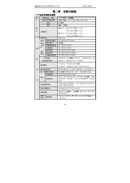
-1-第二章 安装与配线2.1产品技术指标及规格额定电压、频率 三相 380V 50/60Hz输入电压允许变动范围320V~460V; 电压失衡率<3%; 频率±5% 电压 0~380V 频率0Hz ~ 500Hz输 出过载能力G2系列:额定电流*150% / 1分钟,额定电流*180% / 2秒;P2系列:额定电流*120% / 1分钟,额定电流*150% / 2秒。
控制方式 V/F 控制模拟端子输入最大输出频率的 0.1% 数字设定 0.01Hz面板模拟设定最大频率的 0.4 % 频率 设定 分辨 率外部脉冲最大频率的 0.1% 模拟设定最大输出频率的±0.2% 数字设定设定输出频率的±0.01% 频率精度外部脉冲设定最大输出频率的±0.1%V/F 曲线 (电压频率特性) 基准频率在5~500Hz 任意设定,可选择恒转矩、递减转矩1、递减转矩2共三类曲线 转矩提升手动设定:额定输出的0~20%自动提升:根据输出电流自动确定提升转矩 自动节能运行 根据负载情况,自动优化V/F 曲线,实现节能运行。
加、减速时间设定0.1~6000秒连续可设,S 型、直线型模式可选 能耗制动 电机输出额定转矩*75%制动 直流制动启动、停止时分别可选,动作频率0~15Hz ,电机额定电压*(0~15%),动作时间0~20.0秒、或持续动作自动限流功能 快速电流自动抑制能力,防止加速过程中及冲击性负载下频繁过流故障 电压失速防止保证减速过程中不发生过电压载波调整 载波频率1.5KHz ~ 15.0KHz 连续可调,最大限度降低电机噪声控 制 特 性频率设定 信模拟输入直流电压0~10V 、-10V~10V ,直流电流0~20mA (上、下限可选)数字设定 使用操作面板脉冲输入 0~50.000KHz (上、下限可选)启动信号 正转、反转、启动信号自保持(三线控制)可选定时器、计数器 内置定时器、计数器各一个,方便系统集成多段速控制功能/摆频运行 最多7段可编程多段速控制,每段速度的运行方向、运行时间分别可设。
ATL 教程

ATL 教程Visual Studio .NET 2003ATL 旨在简化创建有效、灵活、轻量的控件的过程。
本教程带领您完成创建ActiveX 控件的过程,以阐释许多ATL 和COM 的基础知识。
本教程不使用属性。
有关使用属性的逐步骤指南,请参见属性教程。
通过遵循本教程,您将了解如何将控件添加到绘制圆形和实心多边形的ATL 项目中。
然后您将添加属性,指示多边形有多少条边,并创建在属性更改时更新此控件的绘图代码。
控件然后将显示在Web 页上,并使用一些VBScript 使它对事件做出响应。
教程分为7 个步骤。
应按顺序执行每个步骤,因为后面的步骤依赖于前面完成的任务。
在开始之前,应该确认您具有在特定计算机上注册ActiveX 组件所需的权限。
通常,只有当您在“终端服务”连接上运行Visual Studio .NET 时,才需要注意这一问题。
步骤 1:创建项目Visual Studio .NET 2003本教程将带领您逐步骤通过一个非属性化ATL 项目,该项目创建一个显示多边形的ActiveX 对象。
此对象包括使用户得以更改组成多边形的边数的选项以及刷新显示的代码。
注意本教程创建与Polygon(多边形)示例相同的源代码。
如果您希望避免手动输入源代码,则可以从多边形示例摘要下载源代码。
然后,您可以一边参考Polygon 源代码一边阅读教程,或者用它来检查自己的项目中是否有错误。
使用“ATL 项目向导”创建初始ATL 项目1.在Visual Studio 开发环境中,在“文件”菜单上单击“新建”,然后单击“项目”。
2.单击“Visual C++ 项目”文件夹并选择“ATL 项目”。
3.键入Polygon作为项目名称:源代码的位置通常默认为My Documents\Visual Studio Projects,并且将自动创建一个新文件夹。
4.单击“确定”,“ATL 项目向导”随即打开。
5.单击“应用程序设置”以查看可用选项:6.在创建控件时,如果控件必须是进程内服务器,则将“服务器类型”保留为DLL。
ATL开发技术精要

用ATL开发和部署ActiveX网页控件摘要ActiveX插件技术广泛的运用于B/S系统中,本文通过一个项目实例,详细介绍用ATL 开发和部署ActiveX网页控件的过程。
学习使用ActiveX让浏览器访问客户端的硬件资源。
关键字ATL,ActiveX控件,COM组件一、前言在B/S结构的系统中,出于安全性考虑一般不准许浏览器访问客户端的硬件资源,如控制打印机,照相机等。
对于一个完善系统来说,往往很多时候又需要控制这些资源。
通过在浏览器中插入ActiveX插件是一种很好的解决方式。
在实际的项目开发中,遇到系统登录需要增加物理身份识别。
即在系统登录的时候,除了要验证用户名和密码外,还需要验证硬件USB KEY上的信息。
具体业务流程为:客户端程序读取用户硬件USB KEY里的个人信息(即加密认证信息),提交给认证服务器进行认证,认证服务器通过身份识别后,业务系统通过解析返回的XML信息判断用户是否合法有效,建立起用户和业务系统的信任通道。
读取硬件USB KEY的信息我们通过本例的ActiveX控件来完成。
硬件USB KEY选用飞天诚信的ePass1000ND产品。
二、概念1、ActiveX控件ActiveX是Microsoft提出的一组使用COM(Component Object Model,组件对象模型)使得软件组件在网络环境中进行交互的技术集。
它与具体的编程语言无关。
作为针对Internet应用开发的技术,ActiveX被广泛应用于WEB服务器以及客户端的各个方面。
ActiveX是从Microsoft的复合文档技术—OLE成长起来的。
其基本的出发点是想让某个软件通过一个通用的机构为另一个软件提供服务,可以将其插入到WEB网页或其它应用程序中。
在Internet上的使用,ActiveX特点是:一般软件需要用户单独下载然后执行安装,而ActiveX插件是当用户浏览到特定的网页时,IE浏览器即可自动下载并提示用户安装。
ATE经验手册
GENRAD 经验手册本手册之撰写,是以GENRAD VER 5.7.2之操作软体作说明,往后其版本更新,致操作软体更改,则其相关操作动作亦可能不同,但只要彻底了解各操作动做之意义,则在新软体或其它机种之操作软体,当可找到相对应之操作,这应不是问题.这其中之一个重点,就是外在之接口及信息是会变动,但原理是不会变的,只要能掌握住原理,基础,就能无惧于外在之变动,而轻松适应新的环境.希望本手册能带给读者一些帮助,则已达到本手册撰写之目的.首先要了解genrad是ict测试。
Ict的测试观念是什么?1。
静态测试2。
隔离元件测试3。
只要是用来抓制程问题(开短路,缺件等)。
Ict测试又称为board level测试。
不同于F/T测试(称为system level 或者board edge test)。
本手册共分以下八大项目:一.程序发展准备二.程序发展三.程序及治具Debug四.程序,治具及测试机台之维护五.analog程序的发展六.hybrid 程序的发展七.EPROM的程序发展八.tree的程序发展Changed by bruce_gu1999一. 程序发展准备1.以下将叙述分析电路图时之重点:1) 系统之POWER电路此部份极为重要,务必了解其电源产生方式,因此关系到治具的制作之规格及数字测试时要件,如模糊不清,将造成做数字测试时之不确定性,如某些IC无法动作,是否会破坏IC等.以下为检视POWER 电路时,应注意及了解之部份:a) 找出电路图上所有用到之VCC(电源端).先可不必分类,将所有的VCC列出。
在编辑电源是可分析该电源是要测量的还是要外加的。
b) 找出并分析使系统动作之源头电压(即POWER/B 之输出电压),板子上其它电压即是由这些源头电压经过电感或晶体管控制而产生的.c) 经由上面找出源头电压后,此则为当作程序及治具之电压规格.可在CKT上做进一步的修改。
找出所有的电源端可以为以后的debug OXP和 JX稳定具有一定的作用。
AEMC Model 6471地质电阻测试器用户手册说明书

MODEL 6471Test ground resistance without the need ofauxiliary rods or with the 3- and 4- Point methodsACCESSORIESPRODUCT INCLUDESCAT. #2135.48 MODEL 6471 (without probes)Meter, carrying bag, 110 V/240 V power adapter with US power cord,optical USB cable, rechargeable NiMH battery, and a USB drivewith DataView® software, ground tester workbook and user manual.CAT. #2135.49 MODEL 6471 (with probes)Meter, carrying bag, set of (2) SR182 current probes, 110 V/240 Vpower adapter with US power cord, optical USB cable, rechargeableNiMH battery, and a USB drive with DataView® software, groundtester workbook and user manual.KIT SHOWN 300 FT KIT: CATALOG #2135.50Meter, carrying bag for kit, (2) 300 ft color-coded (red/blue) leadson spools, (2) 5 ft color-coded (red/blue) leads, (2) 100 ft hand-tiedcolor-coded (green/black) leads, set of (2) SR182 current probes,110 V/240 V power adapter with US power cord, optical USB cable,(4) T-shaped auxiliaryground electrodes, setof (5) spaded lugs,100 ft tape measure,rechargeable NiMHbattery, and a USBdrive with DataView®software, ground testerworkbook and usermanual.MN82 CURRENT PROBE(2 mA to 10 Arms)Catalog #2135.71REEL CADDYCatalog #2135.85 Set of (2),for use with ground kit spoolsSR182 CURRENT PROBE(0.5 mA to 40 Arms)Catalog #2135.72GROUND RESISTANCE MEASUREMENT USING 2 PROBESFor systems with parallel ground connections, Models 6471 and 6472are capable of accurately measuring a ground resistance using probesonly. This method involves placing 2 probes around the groundconductor to be tested and connecting them each to the instrument.One probe injects a known signal (32 V/1367 Hz) while the other probemeasures the current circulating in the loop. This method savesconsiderable time when ground testing because it is no longer necessaryto set up auxiliary rods or to disconnect the ground connector.MODEL 6472Use under difficult conditions such as the presence ofhigh stray currents that normally affect accuracyPRODUCT INCLUDESCarrying bag, (110/240) V power adapter with US power cord,optical USB cable, rechargeable NiMH battery, and a USB drive withDataView® software, ground tester workbook and user manual.The Model 6472 provides an automated way to measure the value of theearth/ground using the Fall-of-Potential method and storing measurements.TEST KITS6472 METER300 ft Kit: Catalog #2135.53500 ft Kit: Catalog #2135.54(shown)Refer to page 75 forModel 6472 Kit descriptionsCatalog #2135.35, #2135.36and #2135.37MN82 CURRENT PROBE(2 mA to 10 Arms)Catalog #2135.71REEL CADDYCatalog #2135.85Set of (2), for use withground kit spoolsSR182 CURRENT PROBE(0.5 mA to 40 Arms)Catalog #2135.72ACCESSORIES2 probes required to perform stakeless testingLARGE FUNCTIONAL DISPLAYSFEATURES• Ground Resistance testing using the 2-clamp method(no auxiliary rods needed)• 2- and 4-Point Resistance/Continuity measurement (DCResistance) with automatic polarity reversal• 3-Point Fall-of-Potential measurement with manualor automatic frequency selection• 4-Point Soil Resistivity measurement with automaticcalculation of Rho (ρ) and user selection of theWenner or Schlumberger test method• 3-Point Earth Coupling measurement• Manual and Automatic frequency scan from (41 to5078) Hz for optimum test accuracy in electricallynoisy environments• Selectable test voltage of (10, 16, 32 or 60) V up to250 mA of test current (model dependant)• Auto Power OFF feature• Automatic recognition of all electrode connectionsand their resistance value• S tores up to 512 complete test results in internal memory• Display with automatic backlight when enteringa function• Optically isolated USB communication cable included• Rechargeable NiMH batteries from wall charger orvehicle power (Cat. #2135.43 needed for vehiclepower)• Rugged dustproof and water-resistant field case(IP53 rated in closed position)• Grounding standards IEC 61557 parts 4 and 5 compliant• Includes DataView® software for set up, data retrieval,real-time display, analysis, report generation andsystem configuration• Can also be used for continuity tests on bonding2135.48Ground Resistance Tester Model 6471 (Digital, 3-Point, 4-Point, Clamp-on (SR182 probes not included), DataView Software) 2135.49Ground Resistance Tester Model 6471 (Digital, 3-Point, 4-Point, Clamp-on, (includes 2-SR182 probes), DataView® Software) 2135.50Ground Resistance Tester Model 6471 Kit – 300 ft (Catalog #2135.49 and Catalog #2135.36)2135.51Ground Resistance Tester Model 6472 (Digital, 2-Point, 3-Point, 4-Point, Bond Test, DataView® software)2135.53Ground Resistance Tester Model 6472 Kit – 300 ft (Catalog #2135.51 and Catalog #2135.36)2135.54Ground Resistance Tester Model 6472 Kit – 500 ft (Catalog #2135.51 and Catalog #2135.37)2135.60Ground Resistance Tester Model 6471 Kit – 300 ft w/o Probes (Catalog #2135.48 and Catalog #2135.36)2135.61Ground Resistance Tester Model 6471 Kit – 500 ft w/o Probes (Catalog #2135.48 and Catalog #2135.37)4-POINT-TO-POINTSCHLUMBERGER TESTDATA STORAGE3-POINT FALL-OF-POTENTIAL TESTTWO CLAMP TESTWENNER TESTThe 4-Point test shows leadconnections, Continuity test results,test voltage and currentThe Schlumberger test displays test leadc onnection, soil resistivity (ρ) test resultsand electrode spacingMemory Recall displays test resultsstored at a specific memory locationThe 3-Point Fall-of-Potential test displaystest lead connection, grounding rodr esistance and test electrode resistancesThe 2-Clamp method displaysclamp connection resistance,test current and frequencyThe Wenner test displays test leadc onnection, soil resistivity (ρ) test results,electrode spacing and r esistance2 probes required to perform stakeless testing.GROUND TESTERS MODELS 6471 & 6472 — TYPICAL DATAVIEW ® FUNCTIONAL DISPLAYS2-CLAMP METHOD SETUPSELECTIVE 3-POINT TESTING OF MULTIPLE RODS 2-POINT-TO-POINT FALL-OF-POTENTIAL, STEP-TOUCH POTENTIAL4-POINT-TO-POINTSOIL RESISTIVITY150 FT KITCatalog #2135.35Test Kit for 3-Point testing includes carrying bag,(2) 150 ft color-coded (red/blue) leads onspools, (2) 5 ft color-coded (red/blue) leads,(1) 30 ft lead (green), (2) 14.5 in T-shaped auxiliary ground electrodes, a set of (5) spaded lugs and (1) 100 ft tape measure.300 FT KITCatalog 2135.36Test Kit for 4-Point testing includes carrying bag, (2) 300 ft color-coded (red/blue)leads on spools, (2) 5 ft color-coded (red/blue) leads, (2) 100 ft hand-tied color-coded leads (green/black), (4) 14.5 in T-shaped auxiliary ground e lectrodes, a set of (5) spaded lugs and (1) 100 ft tape measure.500 FT KITCatalog #2135.37Test Kit for 4-Point testing includes carrying bag,(2) 500 ft color-coded (red/blue) leads onspools, (2) 5 ft color-coded (red/blue) leads, (2) 100 ft hand-tied color-coded (green/black) leads, (1) 30 ft lead (green), (4) 14.5 in T-shaped auxiliary ground electrodes, a set of (5) spaded lugs and (1) 100 ft tape m easure.OPTIONAL KITSGROUNDFLEX ® FIELD KITTest active tower grounds safely without de-energizing or disconnecting any cables Unique in the industry!GROUND TESTER 6472 KIT-500 FTIncludes meter, rechargeable NiMH batteries, optical USB cable, power adapter(110/240) V with power cord 115 V US, (2) 500 ft color-coded leads on spools (red/blue), (2) 100 ft color-coded leads (hand-tied, green/black), (1) 30 ft lead (green), (4) T-shaped auxiliary ground electrodes, (1) 100 ft AEMC ® tape measure, DataView ® software, ground tester workbook, user manual on USB drive, (1) carrying bag for meter and (1) carrying bag for kit.GROUNDFLEX ® FIELD KIT 6474Catalog #2136.03 (Includes Ground Tester 6472 KIT-500 FT)Includes GroundFlex ® Adapter Model 6474, Ground Tester Model 6472, (4) GroundFlex ® sensors (16 ft/5 m) with (12) color-coded rings, connection lead, (2) extension leads on H reel (black/green) with color-coded alligator clips, (1) extra black and green alligator clip, (6) BNC extension leads, (1) calibration loop, (3) C-clamps, a carrying case with wheels and handle for meters, carrying bag for meter and kit, (1) inverter 12 V dc to SHOWN: 6474 KITCAT #2135.87GroundFlex ® Sensor 32 ft (10 m) (Model 6474 only)CAT #2135.72Model SR182 AC Current Probe (Models 6471 & 6472)FEATURES• Ground Integrity Measurement• 3- and 4-Point Fall-of-Potential measurement with manual or automatic frequency selection • 4-Point soil resistivity measurement with automatic calculation of Rho (ρ) and user selection of the Wenner or Schlumberger test method • 2- and 4-Wire DC resistance m easurement (Bond testing) with automatic polarity reversal • 3-Point Earth coupling measurement• Automatic frequency scan from (41 to 5078) Hz for optimum test accuracy in electrically noisy environments• Selectable test voltage limit of (10,16, 32, or 60) V with up to 250 mA of test current• Automatic recognition of all electrode connections and measurement of their resistance value • Determines bonding condition of overhead ground conductors• Auto Power OFF management • Optically isolated USB communication• Remote set up and operation of all measurements using DataView ® s oftware supplied • Rechargeable NiMH batteries from wall charger or vehicle power (Cat. #2135.43 needed for vehicle power)• Rugged dustproof and water-resistant field case (IP53 rated in closed position)• Includes DataView ® software for data retrieval, real-time display, analysis, automatic report generation and system c onfigurationAUTOMATIC RECOGNITION AND DISPLAY OF INPUT CONNECTIONS TO MATCH TESTThe connections are displayed and flash if incorrect or absent for the test selected.ES H ES 6472ACCESSORIESCAT #2135.86Lead – BNC 150 ft (46 m) M/F Extension Lead (Model 6474 only)* Performing soil resistivity tests with this kit requires two additional auxiliary electrodes not supplied in the 150 ft kit and one additional test lead. ** Clamp-on Ground Resistance Tester can measure system continuity inclusive of all bonding points.*** Must purchase an additional (2) SR182 or (2) MN82 accessory clamps.。
- 1、下载文档前请自行甄别文档内容的完整性,平台不提供额外的编辑、内容补充、找答案等附加服务。
- 2、"仅部分预览"的文档,不可在线预览部分如存在完整性等问题,可反馈申请退款(可完整预览的文档不适用该条件!)。
- 3、如文档侵犯您的权益,请联系客服反馈,我们会尽快为您处理(人工客服工作时间:9:00-18:30)。
质子交换膜燃料电池薄层亲水电极的初步研究薛琳,丁信伟大连理工大学摘 要:质子交换膜燃料电池(Proton Exchange Membrane Fuel Cell, PEMFC)是一种常温操作的全固态的能量转换装置,具有室温启动,无腐蚀与电解液流失,低噪音,寿命长和输出比功率高达0.5~1.5W/cm2等独特优点。
本文针对以纯氢 纯氧为燃料气源,研究薄层亲水催化层电极PEMFC的发电性能,作为深入研究其性能的基础。
关键词:质子交换膜燃料电池,薄层亲水催化层, 膜电极引言21世纪将是氢能的世纪,随着地下煤气化制氢以及金属合金贮氢等技术的日趋成熟,燃料电池作为把氢能直接连续转化为电能的高效洁净发电装置即将大规模全面进入社会,预计到2017年,30%以上的电力将由燃料电池供给。
燃料电池是一种不经过燃烧直接以电化学反应方式将燃料的化学能转变为电能的发电装置,是一项高效率利用能源而又不污染环境的新技术。
燃料电池有多种类型,按使用的电解液不同分类,主要有磷酸型燃料电池(PAFC)、熔融碳酸盐燃料电池(MCFC)、固体氧化物燃料电池(SOFC)、质子交换膜燃料电池(PEMFC)及碱性燃料电池(AFC)。
90年代初,很有竞争力的燃料电池—质子交换膜燃料电池,在实用化方面取得了突破性进展,并成为当今国际上燃料电池开发的热点。
PEMFC以全氟磺酸型固体聚合物为电解质,Pt为电催化剂,氢或净化重整气为燃料,空气或氧气为氧化剂。
PEMFC具有室温启动,无腐蚀与电解液流失,低噪音,寿命长和输出比功率高达0.5~1.5W/cm2等独特优点,不仅是电动汽车的理想电源,成为世界上各大汽车公司竞相研究的技术热点而且可以应用于航天、军事等特殊领域,并且随着PEMFC生产成本的降低和电池系统技术的优化,在燃料电池电站、电动汽车、高效便携式电源等方面都具有很大的市场潜力。
质子交换膜燃料电池(PEMFC)是近十年以来得到迅速发展的一类新型燃料电池。
PEMFC以全氟磺酸型固体聚合物为电解质,Pt为电催化剂,氢或净化重整气为燃料,空气或氧气为氧化剂。
PEMFC具有室温启动,无腐蚀与电解液流失,低噪音,寿命长和输出比功率高达0.5~1.5W/cm2等独特优点,是电动汽车的理想电源,成为世界上各大汽车公司竞相研究的技术热点而且可以应用于航天、军事等特殊领域,并且随着PEMFC生产成本的降低和电池系统技术的优化,在燃料电池电站、电动汽车、高效便携式电源等方面都具有很大的市场潜力。
随着质子交换膜燃料电池技术的日益成熟,其研究重点将会由前期的开发的电池材料,逐渐转向后期的探索廉价制造工艺以及组装大规模电池堆等方面。
一、质子交换膜燃料电池概述(一) 质子交换膜燃料电池结构及工作原理PEMFC以全氟磺酸固体聚合物为电解质,Pt/C或是Pt-Ru/C为电催化剂,氢或净化重整气为燃料,空气或是纯氧为氧化剂,带有气体流动通道的石墨或表面改性的金属板为双极板。
图1为PEMFC的结构示意图,图2为工作原理示意图。
PEMFC中的阳极催化层中的氢气在电催化剂的作用下发生电极反应H2→2H++2e-该电极反应产生的电子经外电路达到阴极,而氢离子经质子交换膜达到阴极,氧气与氢离子及电子在阴极发生反应生成水,生成的水不会稀释电解质,而是通过电极随反应尾气排出。
1/2O2+2H++2e-→H20图1 质子交换膜燃料电池结构示意图图2 PEMFC工作原理示意图(二) 质子交换膜燃料电池电极的立体化对于以固体为电解质隔膜的质子交换膜燃料电池而言,当将电极与固体膜组合为电池时,由于电解质不能进入电极的催化层,因此电极催化层内无法建立离子通道,不能起电催化剂作用,电化学反应仅能在膜与电催化层交界面处进行。
为扩大反应界面,在制备电极时,可将离子导体,即全氟磺酸树脂,加入电极催化层内,以期在电极内建立离子导电通道。
向电催化层内加入离子导体的技术称为电极的立体化技术。
对由催化剂、憎水剂PTFE和离子导体全氟磺酸树脂构成的电催化层可视为三网络结构的电极电催化层,即由电催化剂构成的亲水网络,起传导电子和水的功能;由憎水剂PTFE构成的憎水网络为气体扩散提供通道;而由全氟磺酸树脂构成的网络起传导质子和水的功能。
(三) 质子交换膜燃料电池的性能影响因素及特点质子交换膜燃料电池有以下的性能影响因素[1-3]:①质子交换膜燃料电池的压力特性:要想获得更高功率密度,PEMFC必须在更高的压力下工作,尤其是对于阴极的反应物而言[13]。
通常来说,在质子交换膜两侧的反应气体的压力要保持平等,这样可将气体通过交换膜的扩散减小到最小程度,而这种反应气体通过质子交换膜的扩散不仅会造成电池电压的下降,更为严重的是会导致氢氧混合物的爆炸。
目前,PEMFC的工作压力范围可以从常压到0.8MPa。
对于不同的应用环境来说,PEMFC的氧化剂类型也不同。
一般来说随着反应压力的下降,在相同的电流密度下,电池的电压是下降的,意味着电池功率密度的下降。
采用H2/O2为反应气时,电池的工作电压明显高于H2/空气系统,在低电流密度时出现的V-I线性区偏离,这种偏离主要是由于“氮障碍层效应”和空气中氧气分压低所造成的[14]这些都会明显降低PEMFC的性能。
②质子交换膜燃料电池的温度特性:PEMFC的温度特性是由质子交换膜所决定的。
目前多数的PEMFC采用Nafion系列膜作电解质,而这种电解质在温度超过80℃时,其热稳定性和质子传导特性会严重下降,因而PEMFC的最佳工作温度为80℃左右。
燃料电池的工作温度对其性能有重要的影响[13]:对于以纯氢为燃料的电池,随着温度的升高,电压-电流密度曲线图上线性区的斜率是降低的,这意味着电池的内阻的减小,这主要归结于电池欧姆电阻的下降。
在相同的电流密度条件下,随着电池温度的升高,燃料电池的工作电压增大,也就是说燃料电池的功率增大。
Tatiana J.P. Freire等人的研究[18]充分证明了这一点,从他所做的实验结果电池内阻-温度图上可明显看出:随温度的升高,电池内阻减小。
另外他还研究了膜的厚度对电池内阻的影响和阴极扩散层对电池内阻的影响等。
而对于燃料中含有CO的电池,Divisek J等人的研究结果表明[16]:电池的工作温度,燃料纯度等过程参数之间是相互影响、相互制约的。
③质子交换膜燃料电池的增湿特性:质子交换膜的电导强烈的依赖于质子交换膜中的水含量。
水含量越高,膜的电导就越大。
膜部分失水时,尤其是处于反应气进口的附近的质子交换膜部分失水,必须对反应气体作增湿处理。
根据D. Singh 等人[17]的两维数值模拟结果,随电流密度的增加,是否需要增湿以及增湿的位置都有所不同,共分五种情况:1)当电流密度小于50 mA/cm2时,发生水从阴极到阳极的反向扩散,因此整个阴极都需要增湿,且进口下游处需要的增湿水平高,整个阳极则不需要增湿处理;2)当电流密度在50-150 mA/cm2之间时,在进口附近不需要增湿,而在进口下游的情况和第一种情况相同;3)当电流密度在50-200 mA/cm2之间时,无论阴极还是阳极都不需要增湿;4)当电流密度在200-2000mA/cm2之间时,阳极进口临近区域需要增湿处理,其余不需要增湿处理;5)当电流密度大于2000 mA/cm2时,整个阳极区域都需要增湿。
质子交换膜燃料电池除具有一般燃料电池的优点外,还有以下特点:⑴ 操作温度低(60℃~100℃),对材料要求低,电池组装相对简单。
可在电池内部实现燃料重整转化过程,简化系统。
⑵ 体积小,质量轻。
⑶ 采用全固体组件,结构紧凑,且固体电解质一般比较稳定,避免了使用液态电解质所带来的腐蚀和电解液流失等问题,可望实现长寿命运行。
⑷ PEMFC的氢电极极化小、能量转化效率高,与其它燃料电池系统相比,其比功率和比能量大,可在低温下快速启动和运行。
(四) 质子交换膜燃料电池研究现状及应用前景近十年以来,由于社会对环保意识和节能意识的关注,使燃料电池的研究逐步加深,这归功于多年来研究成果,其中主要研究有[4]:1、质子交换膜型燃料电池(PEMFC)以全氟磺酸型固体聚合物为电解质,以Pt/C或Pt-Ru/C为电催化剂,以氢或净化重整气为燃料,以空气或纯氧为氧化剂,并以带有气体流动通道的石墨或表面改性金属板为双极板。
2、PEMFC中的电极反应类同于其他酸性电解质燃料电池。
阳极催化层中的氢气在催化剂作用下发生电极反应H2→2H++2e,产生的电子经外电路到达阴极,氢离子经电解质膜到达阴极。
氧气与氢离子及电子在阴极发生反应生成水,即1/2O2+2H++2e-→H2O,生成的水不稀释电解质,而是通过电极随反应尾气排出。
3、温度对PEMFC的性能有显著影响,随温度升高,电解质的欧姆电阻降低,使电池内部电阻降低,传质速度增大,电池性能提高。
4、压力对PEMFC的电池性能有较大的影响。
通过电压-电流曲线看出氧气分压对传质速率有很大影响,一般认为,空气中的氮气阻碍了氧气的传质。
5、 PEMFC所用的电催化剂以Pt为主催化剂组分,降低Pt的含量以及提高Pt的利用率,也是研究的主要内容。
PEMFC的诸多优点使其成为一种极具潜力的发电技术,众多国内外机构纷纷开展了对其的研究和开发工作。
通常单电池(Single Cell)的输出电压只有1V左右,功率也很小,为获得较高的电压和功率,需要将许多单电池连接在一起组成电池组(Cell Stack),如图3所示。
图3 质子交换膜燃料单电池结构及电池组结构图目前开发的绝大多数PEMFC电池组是按压滤机方式组装的,而且大多数采用内共用管道形式[5-6],如图所示。
由图可知,电池组的主体为MEA、双极板及相应的密封件单元的重复,一端为氧单极板,可兼作电流导出板,为电池组的正极;另一端为氢单极板,也兼作电流导入板,为电池组的负极。
与这两块导流板相邻的是电池组端板。
对于民用发电,能量转化效率更为重要。
而对体积功率比与质量功率比的要求居次要地位,因此,在依据用户对电池组工作电压的要求确定串联的单池节数时,一般单池工作电压选在0.70~0.75V之间,这样不考虑燃料利用率时,电池组的效率可达0.560或0.60(LHV)。
PEMFC自身的特点决定了它在许多领域有着广泛的应用前景[7],如:⑴ 未来电动汽车和潜艇等交通器的动力电源;⑵ 便携式电子设备电源;⑶ 现场发电站;⑷军事、航空航天应用等。
二、质子交换膜燃料电池的性能研究通常质子交换膜燃料电池按电极的厚度主要分为两种:厚层憎水催化剂电极PEMFC和薄层亲水催化剂电极PEMFC。
所谓厚层憎水电极是指将一定比例的Pt/C电催化剂与PTFE乳液在水和醇的混合溶剂中超声振荡,调为墨水状,若黏度不合适可加少量甘油类物质进行调整。
