西电控制器中文说明
GU620/621/630/631中文简易说明(11.14)
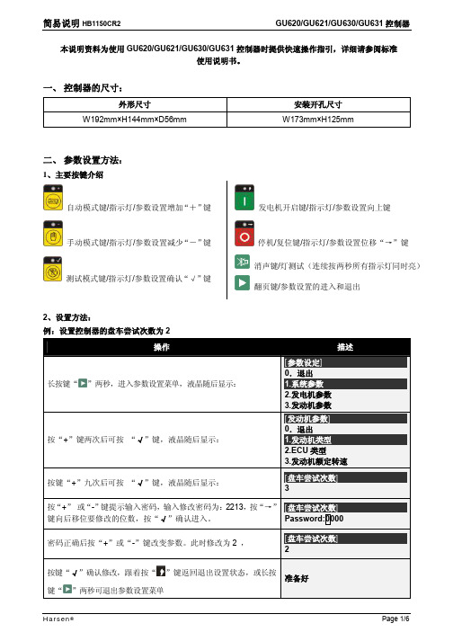
简易说明HB1150CR2GU620/GU621/GU630/GU631控制器本说明资料为使用GU620/GU621/GU630/GU631控制器时提供快速操作指引,详细请参阅标准使用说明书。
一、控制器的尺寸:外形尺寸安装开孔尺寸W192mm×H144mm×D56mm W173mm×H125mm二、参数设置方法:1、主要按键介绍手动模式键/指示灯/参数设置减少“-”键发电机开启键/指示灯/参数设置向上键三、参数设置项目:1、系统参数序号项目预设值序号项目预设值1.1 语言 1.13 显示对比度 51.2 密码 1.14 显示亮度 51.3 油压单位0 1.15 节能亮度 11.4 温度单位0 1.16 自动翻页时间01.5 通讯地址 1 1.17 启动警报01.6 开启模式0 1.18 双机互为备用01.7 电流互感器变比1000:5 1.19 互为备用时间不使用1.8 电压互感器变比 1.0:1 1.20 开关合闸脉冲连续1.9 额定电压值220V 1.21 复位至手动模式01.10 额定电流值1000A 1.22 清除历史事件记录1.11 额定有功功率500kW 1.23 恢复默认值1.12 电压类型 12、发电机参数序号项目预设值序号项目预设值2.1 发电电压监测类型 1 2.11 发电过流2 115%2.2 发电低电压1 90% 2.12 发电超负载1 110%2.3 发电低电压2 85% 2.13 发电超负载2 120%2.4 发电高电压1 115% 2.14 发电开关合闸5秒2.5 发电高电压2 120% 2.15 发电开关分闸5秒2.6 发电低频率1 48.0Hz 2.16 发电带载电压90%2.7 发电低频率2 45.0Hz 2.17 发电带载频率48.0Hz2.8 发电高频率1 55.0Hz 2.18 发电供电延时5秒2.9 发电高频率2 57.0Hz 2.19 测试模式02.10 发电过流1 110% 2.20 软卸载时间5秒3、发动机参数序号项目预设值序号项目预设值3.1 发动机类型 1 3.24 预热模式 13.2 ECU类型 1 3.25 预热时间 3 秒3.3 发动机额定转速1500 3.26 安全监察延时10 秒3.4 速度传感器输入0 3.27 冷却模式 13.5 飞轮齿数120 3.28 冷却时间300秒3.6 设定传感器频率 3.29 停机时间20秒3.7 发电机极对数 2 3.30 外部盘车允许03.8 供油阀类型0 3.31 充电失败8.0V3.9 启动延时10秒 3.32 速度传感器信号功能 13.10 盘车尝试次数3次 3.33 超速等级1 1600 RPM 3.11 危急盘车次数6次 3.34 超速等级2 1710 RPM 3.12 盘车时间5秒 3.35 低速等级1 1440RPM 3.13 盘车时间增加不使用 3.36 低速等级2 1350 RPM 3.14 盘车间隔时间15秒 3.37 启动失败 63.15 点火速度200RPM 3.38 停机失败 33.16 点火开始延时5秒 3.39 电池高电压35.0 V 3.17 燃气阀打开延时5秒 3.40 电池低电压8.0 V 3.18 盘车切断转速300RPM 3.41 保养1000 3.19 盘车切断发电电压85% 3.42 ECU数据故障 23.20 盘车切断充电电压不使用 3.43 ECU警告 2 3.21 盘车切断油压 2.2 Bar 3.44 ECU停机故障 2 3.22 盘车切断油压延时不使用 3.45 油进水 2 3.23 怠速时间不使用4、设置模拟输入序号项目预设值序号项目预设值4.1 压力传感器类型 4 4.20 辅助1高温等级2 100℃4.2 低油压等级值1 1.4Bar 4.21 预热1开水平值50℃4.3 低油压等级值2 1.1Bar 4.22 预热1停水平值60℃4.4 温度传感器类型 3 4.23 冷却1开水平值80℃4.5 高温等级值1 92℃ 4.24 冷却1停水平值70℃4.6 高温等级值2 100℃ 4.25 辅助传感器2 用途 24.7 预热开水平值50℃ 4.26 辅助传感器2类型 34.8 预热停水平值60℃ 4.27 辅助2低压等级1 1.1Bar4.9 冷却开水平值80℃ 4.28 辅助2低压等级2 1.4Bar 4.10 冷却停水平值70℃ 4.29 辅助2高压等级1 8Bar 4.11 辅助传感器1 用途 1 4.30 辅助2高压等级2 10Bar 4.12 辅助传感器1类型 3 4.31 辅助2低温等级1 60℃4.13 低油位等级值1 20% 4.32 辅助2低温等级2 50℃4.14 低油位等级值2 10% 4.33 辅助2高温等级1 90℃4.15 油泵开水平值20% 4.34 辅助2高温等级2 100℃4.16 油泵停水平值70% 4.35 预热2开水平值50℃4.17 辅助1低温等级1 60℃ 4.36 预热2停水平值60℃4.18 辅助1低温等级2 50℃ 4.37 冷却2开水平值80℃4.19 辅助1高温等级1 90℃ 4.38 冷却2停水平值70℃5、设置输入输出序号项目预设值序号项目预设值5.1 开关量输入1定义 6 5.8 继电器1定义 25.2 开关量输入2定义 2 5.9 继电器2定义 15.3 开关量输入3定义 3 5.10 继电器3定义05.4 开关量输入4定义 4 5.11 继电器4定义05.5 开关量输入5定义 1 5.12 继电器5定义05.6 开关量输入6定义 1 5.13 继电器6定义05.7 开关量输入7定义 1 5.14 继电器7定义07、转换控制(仅GU631有此参数项)序号项目预设值序号项目预设值7.1 市电电压监测类型 1 7.12 市电开关合闸5秒7.2 市电低电压故障值90% 7.13 市电开关分闸5秒7.3 市电低电压返回值95% 7.14 电流输入类型07.4 市电高电压故障值115% 7.15 限制返回07.5 市电高电压返回值110% 7.16 市电故障发电负载07.6 市电低频率故障值45.0Hz 7.17 市电超负载故障值120%7.7 市电低频率返回值48.5Hz 7.18 市电超载故障延时5秒7.8 市电高频率故障值57.0Hz 7.19 市电超载故障动作07.9 市电高频率返回值52.0Hz 7.20 市电过电流故障值115% 7.10 市电故障确认时间5秒7.21 市电过流故障延时5秒7.11 市电供电延时5秒7.22 市电过流故障动作08、保养设置序号项目预设值序号项目预设值8.1 日期时间8.13 第二次调度模式08.2 调度周期 1 8.14 第二次开始时间HH:MM8.3 第一次调度模式0 8.15 第二次持续时间60分8.4 第一次开始时间HH:MM 8.16 第二次星期一有效08.5 第一次持续时间60分8.17 第二次星期二有效08.6 第一次星期一有效0 8.18 第二次星期三有效08.7 第一次星期二有效0 8.19 第二次星期四有效08.8 第一次星期三有效0 8.20 第二次星期五有效08.9 第一次星期四有效0 8.21 第二次星期六有效08.10 第一次星期五有效0 8.22 第二次星期日有效08.11 第一次星期六有效0 8.23 数据记录周期不使用8.12 第一次星期日有效0菜单注释:l电压输入类型说明代码定义电压类型代码定义电压类型代码定义电压类型1 星型三相四线2 角型三相四线3 三相三线4 两相三线5 一相两线l传感器类型定义说明代码温度传感器类型油压传感器类型1 高温开关1(低电平有效)低油压开关1(低电平有效)2 高温开关2(高电平有效)低油压开关2(高电平有效)3 VDO120℃VDO 5 bar4 VDO150℃VDO 10 bar5 Datcon Datcon 7 bar6 Murphy Murphy7 bar7 Pt100备注:7-13是定义和自定义项目,请参考详细使用说明书。
控制器操作指南及使用手册
控制器操作指南及使用手册控制器是一种用于控制和管理设备的便携式电子设备。
它具有操作简便、功能强大等特点,广泛应用于工业自动化、机械控制等领域。
本文将为您详细介绍控制器的操作指南及使用手册,以帮助您更好地使用和配置控制器。
一、控制器的基本操作1. 开关机操作:控制器的开机操作通常是通过按下电源按钮来实现的,待控制器正常开机后,屏幕将呈现出操作界面。
关机操作通常是通过按住电源按钮数秒来实现的。
2. 界面导航:控制器的操作界面通常是以菜单形式展示的,您可以通过触摸屏或物理按键来浏览不同的菜单选项。
在菜单中选择所需功能后,按下确定按钮以进入相应操作界面。
3. 参数设置:在控制器的操作界面中,您可以设置不同的参数以调整设备的工作状态。
如输出电流、速度、时间等,这些参数可根据具体的设备和工作需求进行调整。
4. 存储与读取:控制器通常具备存储数据的功能,您可以将特定的参数设置保存到控制器的内部存储器或外部存储介质中。
当需要使用保存的参数设置时,您可以从存储介质中读取并加载到控制器中,实现快速配置。
二、控制器的高级功能1. 程序编辑:控制器通常支持程序编辑功能,您可以根据实际需求创建、修改或删除程序。
程序中包含了设备运行的具体逻辑和控制命令,可以实现自动化、精准的设备操作。
2. 脚本编写:除了程序编辑外,控制器还支持脚本编写功能。
脚本是一种基于特定编程语言的简单指令集,通过编写脚本可以实现更加复杂的设备控制逻辑和操作步骤。
3. 远程控制:某些控制器支持远程控制功能,您可以通过网络连接等方式,远程访问和操控控制器。
这使得您可以在离开控制器所在位置的情况下,依然能够实时监控和控制设备的运行状态。
三、使用手册1. 了解设备:在开始使用控制器之前,建议您先详细了解所控制设备的工作原理和规格要求。
这将有助于您更好地配置和调整控制器的参数,确保设备的正常运行。
2. 操作指南:根据具体的设备和控制器型号,您可以参考控制器的操作指南来了解详细的操作步骤和设置方法。
控制器使用说明书

控制器使用说明书一、产品简介控制器是一种用于控制和管理设备或系统的重要组件。
它通过接收和解析用户输入的指令,并根据指令执行相应的操作,实现对设备或系统的控制和管理。
本文档将详细介绍我们的控制器的功能、操作方法以及注意事项。
二、产品功能1. 控制器具有多种不同的输入接口,包括按钮、滑动条、旋钮等,用户可以根据需要选择适合的操作方式。
2. 控制器能够与各种设备或系统进行连接,如灯光设备、音频设备、电视等,并通过控制信号实现对这些设备或系统的控制。
3. 控制器支持多种控制模式,可以根据用户的需求进行自定义设置,实现不同场景下的控制要求。
4. 控制器具有智能识别功能,能够自动识别并连接可控制的设备或系统,简化使用步骤。
5. 控制器还支持远程控制功能,通过与网络连接,用户可以通过移动设备或电脑进行远程控制,随时随地操控设备或系统。
三、操作方法1. 连接设备或系统:首先,将控制器与需要控制的设备或系统进行物理连接,可以通过插入电源线、USB线或者使用无线连接方式。
确保连接稳定。
2. 电源开关:控制器通常会有一个电源开关,将其打开,显示屏将会亮起,并进入待机或工作状态。
3. 操作界面:控制器通常会配备一个操作界面,可能是一个显示屏、按钮或触摸屏等。
用户可以通过操作界面来进行各种设置和操作。
4. 按钮操作:如果控制器具有按钮,用户可以通过按下按钮来实现相应的控制操作。
根据控制器的不同,按钮的功能和操作方式会有所不同,用户需按照说明进行操作。
5. 滑动条或旋钮操作:如果控制器具有滑动条或旋钮,用户可以通过滑动或旋转来实现相应的控制操作。
通过滑动或旋转的程度来调整控制器发出的信号,从而实现对设备或系统的控制。
6. 菜单设置:控制器通常会提供菜单设置选项,用户可以通过菜单进行各种参数设置、场景选择等操作。
根据提示进行相应操作,确保参数设置正确。
7. 远程控制:如果控制器支持远程控制功能,用户可以使用移动设备或电脑连接到控制器,并通过相应的应用程序进行操控。
南自西电的多功能表使用说明书

南自西电的多功能表使用说明书
1、查看电流、电压参数:V/A键,实现查看和翻屏功能。
2、查看功率参数:“1”键,实现查看系统有功功率P(KW)、无功功率Q(KVar)、视在功率S(KVA)。
3、查看电度:实现查看系统有功电能Ep(KWh)、无功电能
Ea(Kvarh)、视在电能Es(KVAh),其中常规看的电度为;系统有功电能。
Acuvim188操作说明:1、查看电流、电压、功率参数:V/A 键,实现查看和翻屏功能。
2、查看电度:F键,实现查看系统有功电能Ep(KWh),其中常规看的电度为:系统有功电能仪表常见问题排查(确保接线正确情况下):
1)电流测量不准情况:检测CT设置参数是否跟实际CT额定参数一致。
2)电压测量不准情况:检测pT设置参数是否跟实际pT额定参数一致。
3)电度测量不准情况:首先检测电流、电压测量参数是否正确,否则调整相应参数设置。
然后检查实际接线与系统设置接线方式是否正确,否则调整相应参数设置。
XP3000控制器使用手册

ASCON 有限公司 1 型号分类 2 功能键和显示 3 尺寸、安装 4 电线 5 Y2-Y3 辅助输出 6 密码 7 程序配置参数(见附件) 8 操作方向(见附件) 设定温度、自动/手动、锁/记忆、自动旋钮 9 修改操作状态 10 技术参数
1- 型号分类 感谢您选择 ASCON 控制器 XF 系列控制器是最新的微处理控制器,功能强大,使用简便。 其带有自动旋钮,系统辅助起动,及系列通讯用于分配控制网络。 其功能完全,所有可能的变量都可以显现出来。可以根据操作模式配置仪器。 1.1 型号分类 1.2 配置码
定点没有任何变化并且符合参数
写入值。为便于计算远程设定点幅度偏差,可采用以下公式:
=远程设定点幅度。 =比例幅度,用可操作单位表示。 些线性参数的功能,可参考如下图。
=参数插入数。为便于更好地理解这
模拟远程设定点控制零位(N=1,2)。通过此参数可以建立远程设定点最小远程输入信号的起始点(0Vdc
或 4mA)。可输入限制值符合配置比例特别值,
标=远程设定点 -1 设定点目标=远程设定点+本地设定点
获取远程模拟设定点控制(N=1,2)。该参数定义远程设定点偏离限制。 可输入值压缩在-100 至 100
之间。输入压缩在 1 和 100 之间的一个值,看是否有一个直接动作增大模拟信号并且增大远程设定点。输入压
缩在-1 和-100 之间的一个值,看是否有一个相反动作增大模拟信号并且减小远程设定点。输入“0”则远程设
以由控制输出限制所需最小值,输出在参数 YL 和 Yh 之间自由移动。当 X 变量处于比例限制之外,
写入参数无意义,并且输出会指定 Y1 的安全状态。(配置位置 H)。
Y2 处可指定的最大值(G=6…9)。通常控制输出在 0%至 100%之间移动。通过此参数可以
控制器功能介绍说明书
控制器功能介绍说明书一、概述控制器是一种智能化设备,作为自动化系统的核心部件,能够对各种设备和系统进行集中监控和控制。
本说明书将对控制器的主要功能进行详细介绍,以便用户能够充分了解并正确操作控制器。
二、功能一:远程监控控制器具备高效的远程监控功能,用户可以通过网络连接,实时了解被控制设备的状态,并在需要时进行操作。
控制器支持多种远程监控方式,如通过手机APP、电脑软件等,方便用户进行远程操作和监控。
三、功能二:参数设定控制器提供了丰富的参数设定功能,用户可以根据实际需求,灵活设置各种参数,以实现对设备的精确控制。
控制器内置了友好的界面,操作简单直观,即使是非专业人士也能轻松完成参数设置。
四、功能三:自动化控制控制器具备强大的自动化控制功能,用户可以根据需求,设定各种自动化逻辑,实现设备的智能化控制。
控制器支持多种触发条件和动作,可以进行时间控制、传感器触发等多种操作,并能够自动记录操作日志,方便用户进行后续分析和优化。
五、功能四:故障诊断控制器具备故障诊断功能,当设备出现故障时,控制器能够迅速检测并给出详细的故障报警信息,方便用户及时处理。
控制器内置了智能算法,可以对设备进行实时监测,并通过各种传感器和检测器进行数据采集和分析,从而提前预警设备故障,并进行精确诊断。
六、功能五:数据存储与分析控制器支持数据的存储和分析功能,用户可以随时查看设备的历史数据、运行状态和报警记录,并进行数据统计和分析。
控制器内置了强大的数据存储和处理模块,可以实现对大量数据的快速处理和查询,为用户提供可视化的数据分析报告,方便用户进行决策和管理。
七、结语以上是对控制器功能的详细介绍,希望本说明书能够帮助用户更好地理解和使用控制器。
不同型号的控制器功能略有差异,请用户在使用时,结合具体的产品使用说明书进行操作。
如有任何疑问,请及时与我们联系。
感谢您选择我们的控制器,希望它能为您的工作和生活带来便利和效率。
法国西电MICS中文操作说明书

MICS TELYS中文使用说明书目录1.前言1.1安全事项1.2电源连接1.3电气连接(控制)1.4电池预检查和试运行1.5MICS Telys 第一次加电1.6欢迎界面1.7“纵览”界面2.工作模式2.1停机模式2.2编程模式2.3自动模式2.4测试模式3.休眠模式及自动断电3.1休眠模式3.2自动断电4.察看电气指标。
4.1电压4.2电流4.3频率和累计时间5.察看发动机参数6.显示LEDs及灯测试7.屏幕对比度8.显示警报和故障信息8.1屏幕信息8.2清除屏幕信息9.状态信息的显示10.进入一级菜单11“告警/故障”菜单11.1故障特性11.2告警特性11.3其他的特别情况12.“状态”菜单13.“输入”菜单14.“输出”菜单15.“对比度”菜单16.“保护”菜单16.1活动保护16.2通过CIC的保护16.3特别情况17.发电机组的操作17.1水加热器17.2发动机预热17.3油阀控制17.4启动马达控制17.5启动马达的脱离17.6转速和电压稳定17.7发电机组的输出17.8发动机冷机和关机18.ATS的操作18.1停机模式18.2自动模式18.3手动模式1、机油压力故障/停机(红灯亮)2、水温故障/停机(红灯亮)3、过载故障/停机(红灯亮)4、超速故障/停机(红灯亮)5、发电机组带载或准备带载(绿灯亮)6、充电电机报警停机(红灯亮)7、一般报警(黄灯闪烁)8、一般故障/停机(红灯闪烁)自动关闭之后重新开启按钮主菜单按钮确认按钮退出按钮浏览选择按钮及灰度调节数字键盘断开发电机组断路器闭合发电机组断路器电压显示按钮电流显示按钮频率及小时计按钮显示发动机参数按钮自动模式按钮(灯亮)测试模式按钮(灯亮)停止模式按钮(灯亮)手动模式按钮(灯亮)故障复位按钮灯光测试按钮(不包括ON按钮的灯)1.机油压力故障/停机(红灯亮)2.水温故障/停机(红灯亮)3.启动失败故障/停机(红灯亮)4.超速故障/停机(红灯亮)5.发电机组带载或准备带载(绿灯亮)6.充电发电机告警停机(红灯亮)7.综合告警(黄灯闪烁)8.综合故障/停机(红灯闪烁)四、1、前言1、1概述MICS Telys连接到不同交流电压源。
控制器基础使用说明书

控制器基础使用说明书一、控制器概述控制器是一种用于管理和控制系统操作的设备,具有广泛的应用领域。
本文将向您介绍控制器的基本使用方法和操作步骤,帮助您快速上手并顺利完成任务。
二、控制器的组成部分1. 电源:确保控制器能够正常工作的电源供应装置。
请确保接入电源的稳定性和可靠性。
2. 控制面板:控制器的操作界面,通过面板上的各种按钮和指示灯进行参数设置和状态显示。
3. 输入/输出接口:用于与外部设备进行通信和连接,实现控制器与其他设备的数据交换。
4. 处理器:控制器的核心部件,负责接收和处理来自输入接口的数据,控制外部设备的操作。
5. 存储器:用于存储程序代码、数据和参数设置等信息,确保数据的可靠性和稳定性。
6. 通信接口:用于实现控制器与计算机或其他设备之间的数据传输和通信。
三、控制器的基本操作步骤1. 接通电源:将控制器的电源插头插入电源插座,确保电源供应稳定,并确保控制器处于关闭状态。
2. 操作面板介绍:熟悉操作面板上的各个按钮、指示灯和显示屏,了解其对应的功能和状态提示。
3. 参数设置:按照实际需求,使用操作面板上的菜单按钮或参数设置按钮,设置控制器的工作参数。
根据具体的应用场景,设置输入/输出接口的连接方式、通信协议等参数。
4. 程序加载:将预先编写好的程序代码导入控制器中。
通过操作面板或通信接口,将程序代码从计算机或外部存储介质传输到控制器的存储器中。
5. 运行控制器:根据控制器的工作状态和操作要求,按下开始按钮或运行按钮,使控制器开始执行程序代码。
6. 监测和调试:在控制器工作过程中,及时监测控制器的状态和指示灯的提示,确保操作无误。
如有需要,可以进行相应的程序调试和参数优化。
7. 关闭控制器:当控制器的任务完成或需要关闭时,按下停止按钮或关闭按钮,将控制器置于关闭状态。
四、注意事项1. 请仔细阅读和理解控制器的相关说明书和安全规定,确保正确和安全使用控制器。
2. 在操作控制器之前,请确保电源和设备的连接正常,并检查控制器是否处于关闭状态。
法国西电发电机组中文说明
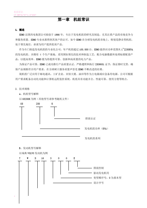
第一章机组常识1.概述SDMO法国西电集团公司始创于1966年,专注于发电机组的研究及制造,尤其注重产品的市场竞争力和服务质量。
SDMO专业水准得到其客户的认可。
如今SDMO在全球发电机组市场上,特别是静音型机组,处于领先地位,承诺为用户提供优质产品。
作为专门制造发电机组的专业化公司,年产机组超过100,000台。
SDMO能供应功率范围从1~2250KVA 的发电机组。
并拥有4个生产基地,采用国际领先的技术和制造工艺,配合电脑数据库处理标准配套产品,以提高效率。
SDMO愿为你提供可靠、创新和高质量的电力产品。
为保证产品可靠,SDMO已成功推行产品质量认证。
严格遵照和执行ISO9001证书,保证准时交货,确保产品规格符合用户要求。
在全球树立服务质量声誉是SDMO不断改进的结果。
现机组广泛应用于邮电通讯、工矿企业、宾馆大厦、油田等作为主电源或应急备用电源。
公司可根据用户要求配备自动化功能和计算机远程监控系统。
机组具有功能齐全、性能可靠、使用方便等特点。
2.技术规格A、机组型号解释以GS250K为例(其他型号请参考随机文件)GS 250 K排放认证发电机组功率(KVA)发电机组系列B、发动机型号解释以瑞典VOLVO发动机为例T W D 16 3 0 G E排放控制驱动发电机用变型顺序号:0为基本型设计序号指示总工作容积柴油机W:水—空中冷型式A:空—空废气涡轮增压C、技术指标工作转速:1500R/mim额定频率:50Hz接线方式:3相4线制额定电压:400/230V功率因素:0.8(滞后)励磁方式:无刷励磁冷却方式:闭式水循环启动方式:DC24V电启动电压:稳定调整率:≤±1%瞬态调整率:≤+20,-15稳定时间:≤1S波动率:≤0.5%频率:稳定调整率:装电子调速器1%(0~5%可调),装机械速器5%。
瞬态调整率:≤±10%稳定时间:≤5S波动率:≤0.5%无线电干扰:符合BS800/2及VDE0875G标准TIF:〈50 THF:〈2%机组保护功能:润滑油油压过高、过低、水温过高,发动机超速,机组过压,过流,短路等保护功能。
「PLC6100系列发电机组控制器使用说明书.」

PLC6100系列发电机组控制器用户手册西安青山电控技术有限公司地址:西安市高新区电子一路18号西部电子工业园C座1001号电话:传真:邮箱:网址:版本发展历史日期版本内容2010-03-05 1.0开始发布2010-06-23 1.1 典型应用图增加了两个可编程输入口:AU X.INPUT4(38脚);AUX.INPUT5(39脚);以及地线(40脚)2010-08-12 1.2 修改了产品外形图片,开孔尺寸长宽各增加2毫米,以及控制器适用的工作温度。
2011-04-09 1.3 更正了一些说明书上的错误2011-09-162.0输出口增加了燃油泵控制选项;输入口增加了自动开机禁止选项和输入口有效状态选择。
2011-11-05 2.1 输出口增加了高速控制选项;编程参数项增加了温度高、油压低禁止停机项;传感器曲线输入范围有所改动。
2012-03-15 2.2 增加了5个可编程输出口选项。
是本公司智能控制器产品的商标不经过本公司的允许,此说明书的任何部分不能被复制(包括图片、图标及文字)和传播。
本公司保留更改此说明书的内容的权利。
目录1.ﻩ概述ﻩ错误!未定义书签。
2.性能和特点ﻩ错误!未定义书签。
3.ﻩ规格ﻩ错误!未定义书签。
4.ﻩ操作 .................................................................................................................. 错误!未定义书签。
4.1ﻩ按键功能描述ﻩ错误!未定义书签。
4.2ﻩ自动开机停机操作ﻩ错误!未定义书签。
4.3ﻩ手动开机停机操作 .................................................................. 错误!未定义书签。
5.ﻩ保护ﻩ错误!未定义书签。
5.1ﻩ警告ﻩ错误!未定义书签。
Schneider-Electric IHP 1C 2C 定时器控制器用户指南说明书
d d _E N 02/19IHP 1C/2CProduct information / menu descriptionCCT15440CCT15441CCT15442CCT15443d d _E N 02/19The IHP with weekly program controls lighting, air conditioning, flushing, etc.|The device must not control safety-relevant applications.G etting to know the timerDisplays and operating elementsA Time displayB Channel stateC Date displayD Programmed ON timesE Display of week daysF Display of active buttonsG OK buttonH Selection buttonsI MENU buttonOperationButton FunctionMENU button•Opens the menu•In menu mode: one step back:•In programming mode: cancel programming modeSelection buttons •Switch between menu items •Increase/decrease value OK button•In menu mode: select menu item •In programming mode: confirm settingMenu structurePROGRAM TIME/DATEMANUAL CONFIG ENDCHANNEL 1TIME CHANNEL 1LANGUAGENEW SET DATEPERM ON PIN CHECK SU-WI PERM OFF FACTORY SETTINGSMODIFY WEEK DAY OVERRI ONINFO DELETEFORM DATE HOLIDAYENDENDFORM TIMEENDd d _E N 02/19The basic settings, such as date, time, etc., must be carried out when starting for the first time or following a reset.The device starts in the settings menu with the item LANGUAGE .1Select the language.2Confirm the message FORM DATE .3Select the date format.4Set the year.5Set the month.6Set the day.7Confirm the message FORM TIME .8Select the time format.9Set the hours.0Set the minute.^Select summer time/winter time.A switching time always consists of one time at which the load is switched on and one time at which the load is switched off. Y ou can either set switching times for a specific day of the week or copy them for multiple week days. Copied week days are referred to as a block.T o set a switching time, perform the following steps once for ON and once for OFF :1Confirm message about free memory slots.2Select ON or OFF .3Set the hour.4Set the minute.5Set the day of the week.6If the switching time is only to be valid for one week day, select SAVE .The switching time is set.7If the switching time is to be copied as a block for multiple week days, select COPY .8Select further days of the week and confirm in each case.Week days contained in the block are indicated in the week days display.To remove a week day from the block, select the week day again using the selection buttons.9Once the desired week days have been set, select COPY .Initial setupSetting a switching timePROGRAMCHANNELC1CHANNELC2NEWNEWd d _E N 02/19Y ou can change the time for the switching times. In the case of switching times within a block, you can select whether the modification of the time is to apply to the whole block or only to a specific week day. This week day is then removed from the block.1Select the switching time.The display runs through all switching times in sequence. If no switching time is set for a week day, this is indicated in the display by --:--.If the selected switching time is part of a block, all days of the block are shown in the week day display. The selected week day flashes.2Set the hour.3Set the minute.4If the selected switching time is only set for one week day, only the option SAVE appears.5If the selected switching time is part of a block, select MODIFY BLOCK or MODIFY WEEK DAY .- MODIFY BLOCK changes the time for all switching times of the block.- MODIFY WEEK DAY changes the time for the selected switching time. The selected switching time is re-moved from the block.Y ou can delete switching times at any time. If a switching time is part of a block, you can delete the entire block or remove the switching time from the block. Y ou can also delete all switching times of a channel simultaneously.Deleting a switching time:1Select SINGLE .2Select the switching time.The display runs through all switching times in sequence. If no switching time is set for a week day, this is indicated in the display by --:--.If the selected switching time is part of a block, all days of the block are shown in the week day display. The selected week day flashes.3If the selected switching time is only valid for one week day, only the option DELETE WEEK DAY appears.4If the selected switching time is part of a block, select DELETE BLOCK or DELETE WEEK DAY .- DELETE BLOCK deletes all switching times of the block.- DELETE WEEK DAY removes the selected switching time from the block and deletes it.Deleting all switching times of a channel:1Select DELETE ALL .2Confirm with CONFIRM .Modifying a switching timePROGRAMCHANNELC1CHANNELC2MODIFYMODIFYDeleting a switching timePROGRAMCHANNELC1CHANNELC2DELETEDELETEd d _E N 02/19With the holiday function, you can switch a channel on or off completely for a longer period. The programmed switching times do not apply while the holiday function is active. Y ou can only set one holiday time per channel.1Select ON or OFF .2Confirm BEGIN HOLIDAY .3Set the year.4Set the month.5Set the day.6Set the hour.7Confirm END HOLIDAY .8Set the year.9Set the month.0Set the day.^Set the hour.A PIN protects against unauthorized use.If you have forgotten your PIN, contact the Customer Care centre in your country, stating the serial number of your device.1Select WITH PIN .NO PIN cancels the PIN protection function.2Confirm CURRENT PIN .3Set new PIN.|The PIN digits are set one after the other with +/- and confirmed with OK . A digit that has already been set can no longer be changed. When the last digit is confirmed with OK , the PIN is saved. If in any doubt, exit the PIN setting procedure with MENU .Setting the holiday functionMANUALCHANNELC1CHANNELC2HOLIDAYHOLIDAYSetting the PINCONFIGPINd d _E N 02/19Y ou can set override or permanent switching either via the MANUAL menu or using combinations of buttons on the device.Override switchingIf you wish to switch a channel briefly to the other switching state (e.g. from ON to OFF ), activate override. This state is only valid until the next switching time.If override is active, CHANNEL OVERRIDE appears briefly in the display.Permanent switchingIf you wish to switch a channel permanently, activate permanent switching. While permanent switching is activat-ed, switching times have no effect.If you want to select whether the channel is to be switched ON or OFF permanently, use the MANUAL menu.If you use the button combinations to activate permanent switching, the channel is switched to the other switching state (e.g. from ON to OFF ).If permanent switching is active, CHANNEL PERMANENT appears briefly in the display.Activating override and permanent switchingd d _E N 02/19Y ou can reset the basic settings, such as date, time, etc. and delete or keep all switching times.Y ou have two options: Y ou can either load the factory settings via the CONFIG menu or reset the device using combinations of buttons on the device.|Loading the factory settings will also delete all switching times. If you want to reset the basic settings and retain the switching times, use the reset function.Loading factory settings1Confirm the message LOAD FACTORY SETTINGS .2Set basic settings as described in chapter “Initial setup”.Resetting1Push all four buttons on the device simultaneously.2Select the language.3If you want to retain the switching times, select RETAIN PROGRAMS .4If you want to delete all switching times, select DELETE PROGRAMS .5Set basic settings as described in chapter “Initial setup”.If you have technical questions, please contact the Customer Care Centre in your /contactResetting basic settingsCONFIGFACTORY SET-TINGSSchneider Electric Industries SAS。
西电瑞电 EKL-5 温度及故障面板型故障指示器 产品说明书
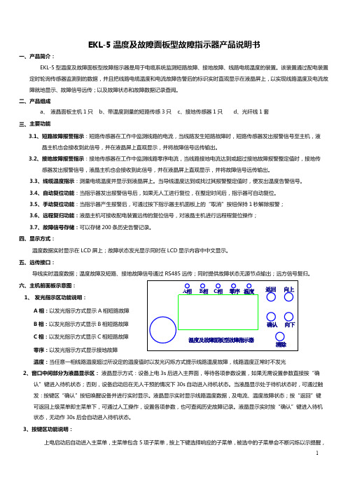
EKL-5温度及故障面板型故障指示器产品说明书一、产品简介:EKL-5型温度及故障面板型故障指示器是用于电缆系统监测短路故障、接地故障、线路电缆温度的装置。
该装置通过配电装置定时轮询传感器监测到的数据,并且把线路电缆温度和电流故障告警后的标识实时直观显示在液晶屏上,以实现线路温度及电流故障就地显示、故障信号远传;以及故障状态和故障数据记录查阅。
二、产品组成a、液晶面板主机1只b、带温度测量的短路传感3只c、接地传感器1只d、光纤线1套三、主要功能3.1、短路故障报警指示:短路传感器在工作中监测线路的电流,当线路发生短路故障时,短路传感器发出报警信号至主机,液晶主机也会接收到此信号,并在液晶屏上直观显示,并将故障信号远传输出。
3.2、接地故障报警指示:接地传感器在工作中监测线路零序电流,当线路接地电流达到或超过接地故障报警整定值时,接地传感器发出报警信号,液晶主机也会接收到此信号,并在液晶屏上直观显示,并将故障信号远传输出。
3.3、线缆温度指示:测量电缆温度并显示到液晶屏上。
当导线温度达到或找过其报警整定值时,便发出温度告警信号。
3.4、自动复位功能:当指示器发出报警信号后,如果无人工进行复位,在整定时间后,指示器可自动复位。
3.5、手动复位功能:当指示器产生报警后,可通过按下指示器主机面板上的“取消”按钮保持1秒解除报警;3.6、远程复归功能:液晶主机可接收配电装置远传的复位信号,对液晶主机进行远程程复位操作;3.7、故障信号存储:可以存储200条历史告警记录。
四、显示方式:温度数据实时显示在LCD屏上;故障状态发光显示同时在LCD显示内容中中文显示。
五、远传接口:六、主机前面板示意图:1、发光指示区功能说明:A相:以发光指示方式显示A相短路故障B相:以发光指示方式显示B相短路故障C相:以发光指示方式显示C相短路故障零序:以发光指示方式显示接地故障温度:当任意一相线路温度超过所设定的温度值时以发光闪烁方式提示线路温度故障,线路温度正常时不发光2、窗口中间部分为液晶显示区:液晶显示方式:设备上电3s后进入主界面,等待各项参数设置,如果无需设置参数直接按“确认”键进入待机状态;否则,设备启动后在无人干预的情况下30s自动进入待机状态。
西门子 通用控制器RLU2. 说明书
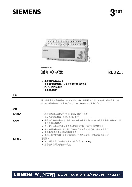
CE1N3101en Siemens Building Technologies3101Synco™ 200通用控制器RLU2...• 带有预置的标准应用• 自由编程的控制器,以适用于相关型号的设备 • P-, PI, 或 PID 模式 • 菜单驱动操作用途用于从基本到复杂的通风、空调和制冷设备。
通用控制器用于处理以下控制变量:温度、相对/绝对湿度、压力/压力差、气流、室内空气质量和焓值。
功能 • 通过状态输入选择运行模式: 舒适、经济、保护 • 显示当前运行模式 (舒适、经济、保护)• 带有各自的顺序控制器: 独立可调节的加热和冷却设定点(或最大和最小设定点)用于舒适和经济模式• 通过室内操作单元或设定点再调节器(无源)预定义室温设定点• 用各种顺序控制器: 用远程设定点调节器(有源或无源)预定义设定点 • 带夏季和/或冬季补偿的室温设定点• 用各种顺序控制器: 设定点偏移取决于传感器信号、可选的起点和终点 通用输入:• 不同测量值的无源或有源模拟输入信号 (°C, %, ---) • 数字输入信号(无电压干节点)操作模式 设定点通用输入3101P 032/26• 用于两个供热顺序(反向作用)和两个冷却顺序(正向作用)的通用控制器(顺序控制器) 可以作为提供P-, PI 或PID 模式的控制器,也可以作为差动控制器 • 控制器可以配置为室内/送风气温串级控制器,同时限制送风温度。
• 各顺序可指定为调节输出控制(调节输出、步进开关、混风风门、热回收设备)和泵。
2个顺序可同时作用于相同的调节输出控制(如优先冷却/除湿)• 一般限制功能 (每个顺序控制器以PI 模式形成最大/最小功能 ),可用于绝对限制(如送风气温或送风湿度),也可用于相对温度限制(如室内/送风气温温差)。
限制对所有的顺序都有所用。
当冷却打开(如用直接膨胀制冷盘管)时,对较低的设定点可以设置下限。
• 每个顺序控制器用PI 模式的顺序控制功能,可以定义为下限或上限。
Xicter控台说明(中文版)

状态按钮:
FIXT:电脑灯编程状态 DIM :传统灯编程状态 CUE:程序调用状态 CL:即cuelist,为程序列表状态
Xicter基本教学教程
前后控制按钮
Xicter基本教学教程
微调开启开关
垂直控制按钮 水平垂直 控制摇杆
水平控制按钮
Xicter基本教学教程
确认按钮 取消按钮
Xicter基本教学教程
两种程序调用方式的关系
Xicter基本教学教程
程序控制列表(Cuelist或CL)
Xicter基本教学教程
程序的调用
通过ESC键可以退出到初始画面,在初始画面按CUE按键,这时候 键可以退出到初始画面,在初始画面按 按键, 通过 键可以退出到初始画面 按键 就会进入程序调用状态, 就会进入程序调用状态,刚才所保存的程序会出现在相对应的推子或 按键上,要调用保存在推子上的程序只需要把推子推上即可, 按键上,要调用保存在推子上的程序只需要把推子推上即可,当然可 以通过推两条推子来出现程序的叠加,可以通过推FREEZE推子对现 以通过推两条推子来出现程序的叠加,可以通过推 推子对现 有程序的速度作临时小幅度修改,这也是为什么要把FREEZE推子推 有程序的速度作临时小幅度修改,这也是为什么要把 推子推 到中间的原因。如果是保存在按键上的程序即按数字键调用。 到中间的原因。如果是保存在按键上的程序即按数字键调用。 如果要对现有程序作临时修改,即在现在的基础上按FIXT或DIM按 如果要对现有程序作临时修改,即在现在的基础上按 或 按 如上面编程的步骤进行修改。退出回原程序按ESC键。 键,如上面编程的步骤进行修改。退出回原程序按 键 再按CUE键,出现是否退出程序调用状态的提示,按YES就可退出 再按 键 出现是否退出程序调用状态的提示, 就可退出 到初始画面
西电机工业电机与控制器型号L-41电子互锁说明书

EvBJt.Y HousB NBBDs WBsTINGHousB
I
RENEWAL PARTS DATA 24-447
I
JANUARY, 1937
WESTINGHOUSE INDUSTRIAL MOTORS AND CONTROLLERS
PAGE 2
The interlock base is secured directly to the contactor panel or mounting plate, employing studs for insulation panel mounting or machine screws inserted from the rear for LINESTARTER on steel plate mounting. The threaded holes provided in the interlock base to receive the mounting screws or studs are completely insulated from current-
Extra Terminals
For the convenience of the user, the interlock base is provided with holes to receive extra terminals (22, F1g. 1), insulated from current-carrying parts and from ground. These will be found especially useful when it is desired to operate the contactor coil from a separate control circuit, or when unusual master switch connections are to be made.
西门子 PLC 控制器说明书
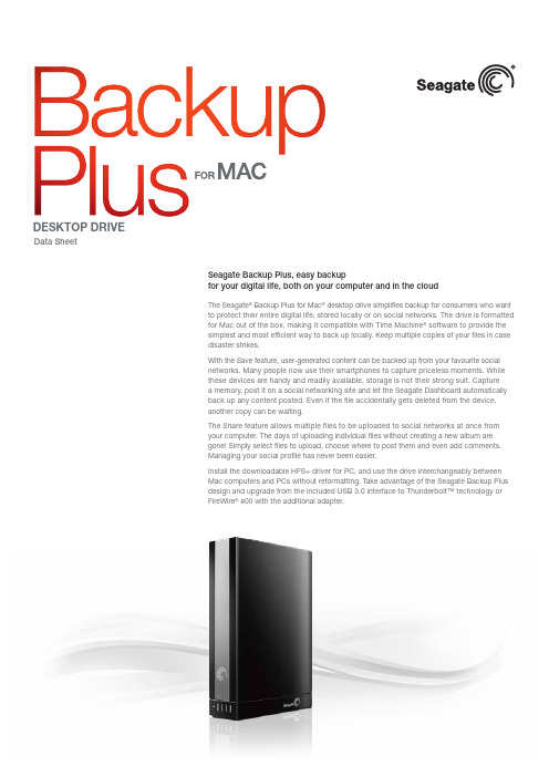
Seagate Backup Plus, easy backupfor your digital life, both on your computer and in the cloudThe Seagate ® Backup Plus for Mac ® desktop drive simplifies backup for consumers who want to protect their entire digital life, stored locally or on social networks. The drive is formatted for Mac out of the box, making it compatible with Time Machine ® software to provide the simplest and most efficient way to back up locally. Keep multiple copies of your files in case disaster strikes.With the Save feature, user-generated content can be backed up from your favourite social networks. Many people now use their smartphones to capture priceless moments. While these devices are handy and readily available, storage is not their strong suit. Capture a memory, post it on a social networking site and let the Seagate Dashboard automatically back up any content posted. Even if the file accidentally gets deleted from the device, another copy can be waiting.The Share feature allows multiple files to be uploaded to social networks at once from your computer. The days of uploading individual files without creating a new album are gone! Simply select files to upload, choose where to post them and even add comments. Managing your social profile has never been easier.Install the downloadable HFS+ driver for PC, and use the drive interchangeably between Mac computers and PCs without reformatting. Take advantage of the Seagate Backup Plus design and upgrade from the included USB 3.0 interface to Thunderbolt™ technology or FireWire ® 800 with the additional adapter.Data SheetDESKTOP DRIVEDESKTOP DRIVEHFS+ driver for PC operability available by downloadCompatibility may vary depending on user’s hardware configuration and operating system.When referring to drive capacity, one terabyte, or TB, equals one trillion bytes.AMERICAS Seagate Technology LLC 10200 South De Anza Boulevard, Cupertino, California 95014, United States, +1 408 658 1000ASIA/PACIFIC Seagate Singapore International Headquarters Pte. Ltd. 7000 Ang Mo Kio Avenue 5, Singapore 569877, +65 6485 3888E UROPE, MIDDLE EAST AND AFRICA Seagate Technology SAS 16-18 rue du Dôme, 92100 Boulogne-Billancourt, France, +33 1 41 86 10 00© 2013 Seagate Technology LLC. All rights reserved. Seagate, Seagate Technology and the Wave logo are trademarks or registered trademarks of Seagate Technology LLC or one of its affiliated companies in the United States and/or other countries. Thunderbolt and the Thunderbolt logo are trademarks of Intel Corporation in the USA and/or other countries. All other trademarks or registered trademarks are the property of their respective owners. When referring to drive capacity, one gigabyte, or GB, equals one billion bytes and one terabyte, or TB, equals one thousand billion bytes. Your computer’s operating system may use a different standard of measurement and report a lower capacity. In addition, some of the listed capacity is used for formatting and other functions and will not be available for data storage. Complying with all applicable copyright laws is the responsibility of the user. Seagate reserves the right to change, without notice, product offerings or specifications. DS1759.4-1302GB。
西电Foxboro DCS系列产品说明书

Foxboro ™ DCSFBM243/243b, FoxCom Dual Baud Rate, Intelligent Device ModulesPSS 41H-2S243Product SpecificationAugust2019Legal InformationThe Schneider Electric brand and any trademarks of Schneider Electric SE and itssubsidiaries referred to in this guide are the property of Schneider Electric SE or itssubsidiaries.All other brands may be trademarks of their respective owners.This guide and its content are protected under applicable copyright laws and furnishedfor informational use only.No part of this guide may be reproduced or transmitted inany form or by any means(electronic,mechanical,photocopying,recording,orotherwise),for any purpose,without the prior written permission of Schneider Electric.Schneider Electric does not grant any right or license for commercial use of the guideor its content,except for a non-exclusive and personal license to consult it on an"as is"basis.Schneider Electric products and equipment should be installed,operated,serviced,and maintained only by qualified personnel.As standards,specifications,and designs change from time to time,informationcontained in this guide may be subject to change without notice.To the extent permitted by applicable law,no responsibility or liability is assumed bySchneider Electric and its subsidiaries for any errors or omissions in the informationalcontent of this material or consequences arising out of or resulting from the use of theinformation contained herein.Overview FBM243/243b,FoxCom Dual Baud Rate,Intelligent DeviceModulesOverviewThe FBM243,FoxCom Dual Baud Rate,Intelligent Device Module contains eightindividual channels.The FBM243b,FoxCom Dual Baud Rate,Intelligent DeviceModule contains four individual input channels and four0to20mA analog outputchannels.Each input provides internal isolated power and digital communication capabilities to aFoxboro Intelligent Field Device.Each channel communicates over a single twistedpair of wires and each channel of the FBM243/243b is channel isolated.The modules also allow the use of an external power supply to power the IntelligentField Device.(The use of an external power supply common to two or more loopsneeds the use of a cable balun module to maintain digital communication linebalance).The baud rate is determined by the configuration of the field deviceconnected to each channel,independently of the other channels.The modulesprovide bidirectional digital communication at4800baud rate between the IntelligentField Device and the system redundant Fieldbus,or provides bidirectional digitalcommunication at600baud rate between the field device and the modules whileallowing a simultaneous4to20mA analog signal from the field device to anemergency shutdown system.The FBM243/243b is an Intelligent Field Device host,enabling the system to receivedigital messages from the field device in engineering units.Each message is receivedten times per second at4800baud,and two times per second at600baud.Eachmessage contains:•Up to three measured variables in IEEE32-bit floating-point format•Security information•Diagnostics•Message checkingThis information is available to each of the elements of the system.Since communication is bidirectional,the system can display the output,transmittertemperature(°C and°F),and the results of continuous self-diagnostics.In addition,the following information can be displayed or reconfigured from a console,a FieldCommunicator,or PC-Based Configurator:•Output in engineering units•Fail-safe information•Tag number,name and location•Device name(letterbug)•Last calibration date•Two levels of upload/download capabilitiesWhen connected to the appropriate TAs,the FBM243/243b modules providefunctionality formerly provided by the100Series FBM I/O subsystem.TAs areavailable for the FBM243that support the functionality of the100Series FBM18andFBM43.TAs are available for the FBM243b that support the functionality of the100SeriesFBM39and FBM44.FBM243/243b,FoxCom Dual Baud Rate,Intelligent DeviceModules Features Features•For the FBM243,8individual digital communication channels•For the FBM243b,4individual dual baud,FoxCom communication channels andfour0to20mA analog output channels•Receives messages10times per second at4800baud,or2times per second at600baud,and contains:◦Up to3measured variables in IEEE◦32-bit floating-point format◦Security information◦Diagnostics◦Message checking•Allows use of an external power supply or the FBM243internal isolated power topower the Intelligent Field Device•Digital communication capabilities to a Foxboro Intelligent Field Device over asingle twisted pair of wires•Allows a simultaneous4to20mA analog signal from the field device to anemergency shutdown system•Termination Assemblies(TAs)for locally or remotely connecting field wiring to theFBM243•Termination Assemblies(TAs)for non-intrinsically safe or intrinsically safeapplicationsFeatures FBM243/243b,FoxCom Dual Baud Rate,Intelligent DeviceModulesStandard DesignThe FBM243/243b has a rugged extruded aluminum exterior for physical protection ofthe circuits.Enclosures specially designed for mounting of the FBMs provide variouslevels of environmental protection,up to harsh environments per ISA StandardS71.04.Visual IndicatorsLight-emitting diodes(LEDs)incorporated into the front of the module provide visualindication of the module operational status,and communication activity of the inputchannels.Easy Removal/ReplacementThe module can be removed/replaced without removing field device terminationcabling,power,or communication cabling.Figure1-FBM243/243b I/O ConfigurationFBM243/243b,FoxCom Dual Baud Rate,Intelligent DeviceModules Features Fieldbus CommunicationThe Fieldbus Communications Module(FCM)or the Field Control Processor(FCP)interfaces to the redundant2Mbps module Fieldbus used by the FBMs.TheFBM243/243b accepts communication from either path(A or B)of the2MbpsFieldbus.If one path is unsuccessful or is switched at the system level,the modulecontinues communication over the active path.Modular Baseplate MountingThe FBM243/243b mounts on a Standard200Series Modular Baseplate(see Figure1),which accommodates up to four or eight Fieldbus Modules.TheModular Baseplate is either DIN rail mounted or rack mounted,and includes signalconnectors for redundant Module Fieldbus,redundant independent dc power,andtermination cables.Termination AssembliesField I/O signals connect to the FBM subsystem via DIN rail mounted terminationassemblies(TAs).For the FBM243,TA RH931KJ contains a51ohm resistor in series with each channelfor use in non-intrinsically safe applications.TA RH917XW is a direct channel for use in intrinsically safe applications.An intrinsicsafety barrier needs to be connected to each channel of this TA providing thenecessary resistance for each channel.TAs RH931KJ,RH917XW,and RH931KJ are available in Polyamide material.For the FBM243b,TAs RH924QQ and RH924QY are available for use in non-intrinsically safe applications.TA RH924QY has output bypass jacks that help removeFBMs from service during system maintenance.An Output Bypass Station providesmanually driven milliamp output signals through the bypass jacks to deter interruptionof the process output signals.The DIN rail mounted TAs connect to the FBM subsystem baseplate by means of aremovable termination cable.The cable is available in a variety of lengths,up to30meters(98feet),allowing the TA to be mounted in either the enclosure or in anadjacent enclosure.Termination cables are available in these materials:•Polyurethane•Low Smoke Zero Halogen(LSZH)Refer to Table1.Features FBM243/243b,FoxCom Dual Baud Rate,Intelligent DeviceModulesCable Balun ModuleA Cable Balun Module maintains digital communication line balance for IntelligentField Devices connected in FBM loops that are powered from a common externalpower supply.This powering method effectively connects one line of each loop to asingle point.(Without the baluns,the multiple common connections at the externalpower source cause communication cross-talk between the loops.)Baluns are notneeded for loops that use internal power sourcing(powered from the FBM).TheCable Balun Module(RH903SV)contains four baluns,with one balun used for eachloop powered from the external power supply.Each balun adds28ohms of resistanceto its associated loop.FBM243/243b,FoxCom Dual Baud Rate,Intelligent DeviceModules Functional Specifications Functional SpecificationsFunctional Specifications FBM243/243b,FoxCom Dual Baud Rate,Intelligent DeviceModulesFBM243/243b,FoxCom Dual Baud Rate,Intelligent DeviceSpecificationsModules FunctionalEnvironmental SpecificationsFBM243/243b,FoxCom Dual Baud Rate,Intelligent DeviceModulesEnvironmental SpecificationsNOTE:The environmental limits of this module may be enhanced by the type of enclosure containing the module.Refer to the applicable Product Specification Sheet (PSS)that describes the specific type of enclosure that is to be used.FBM243/243b,FoxCom Dual Baud Rate,Intelligent Device ModulesPhysicalSpecificationsPhysical SpecificationsPhysical Specifications FBM243/243b,FoxCom Dual Baud Rate,Intelligent DeviceModulesFBM243/243b,FoxCom Dual Baud Rate,Intelligent DeviceModules Physical SpecificationsTable1-Termination Cable Types and Part NumbersUpgrade Use of Termination AssembliesWhen an FBM243/243b is used to replace the100Series FBM,it may use any of theappropriate termination assemblies listed in this PSS for the100Series FBM’s fieldI/O wiring.Alternatively,the FBM243/243b can accept this field wiring through aTermination Assembly Adapter(TAA)instead of a termination assembly.This isdiscussed in Termination Assembly Adapter Modules for100Series Upgrade(PSS41H-2W4).Dimensions-Nominal FBM243/243b,FoxCom Dual Baud Rate,Intelligent DeviceModulesDimensions-NominalFigure2-Termination Assemblies(a)Overall width—for determining DIN rail loading.(b)Height above DIN rail(add to DIN rail height for total).FBM243/243b,FoxCom Dual Baud Rate,Intelligent DeviceModules Related Product Documents Related Product DocumentsWARNING: This product canexpose you to chemicalsincluding lead and leadcompounds, which areknown to the State ofCalifornia to cause cancerand birth defects or otherreproductive harm. For moreinformation, go to/. Schneider Electric Systems USA,Inc.38Neponset AvenueFoxborough,Massachusetts02035–2037United States of AmericaGlobal Customer Support:https://As standards,specifications,and design change from time to time,please ask for confirmation of the information given in this publication.©2015–2019Schneider Electric.All rights reserved.PSS41H-2S243,Rev A。
西门子程控器中文说明

不要开启、乱动或更改控制装置!
• 所有过程(装配、安装和维修工作等)必须由专业人员进行 • 在变动 LDU11 连接区域的线缆之前,要完全确保装置与所有的电源已经断开 • 确保抗电流冲击的保护装置已经启用,该保护装置为阀门验证装置的的接线端子提供
必要的保护 • 确保接线的正确整洁有序 • 只能手动的按下锁定复位按钮(不超过 10N 的压力),不要使用任何工具或尖锐的物
Siemens Building Technologies HVAC Products
7/16
CC1N7696en 02.06.2004
长管道的泄漏率计算
QLeck
=
(PG
- PW) Patm
x x
V x 3600 tTest
Legend 举例 注意
Qleck PG PW Patm V Ttest
运输 气候条件 机械条件 温度范围 湿度范围 运行 气候条件 机械条件 温度范围 湿度范围
禁止冷凝水、冰和水侵入!
AC 220 V –15 %...AC 240 V +10 % AC 100 V –15 %...AC 110 V +10 % AC 220 V –15 %...AC 240 V +10 % AC 100 V –15 %...AC 110 V +10 %
6/16
Siemens Building Technologies HVAC Products
CC1N7696en 02.06源自2004程序和切断指示 符号的意义
注意 失电时的控制程序
在发生锁定切断的情况下,逻辑控制程序停止,这样位置指示根据机械轴的位置来确定。. 阅读标记上的停止符号指示了当切断发生时所处的测试阶段,并且给出了从测试开始已经 完成的步骤(1 个步骤=2.5 秒)。
控制器操作指南说明书

控制器操作指南说明书一、产品概述控制器是一种用于控制设备或系统操作的装置。
本说明书将详细介绍控制器的使用方法及功能。
二、控制器功能简介1. 功能一:XXX功能控制器可实现XXX功能,通过XXX操作,用户可以进行XXX 操作。
2. 功能二:XXX功能控制器支持XXX功能,使用户能够轻松实现XXX操作。
3. 功能三:XXX功能用户可以利用控制器完成XXX功能,简化操作流程,提高工作效率。
三、控制器外部界面说明1. 接口一:XXX接口该接口用于连接XXX设备,用户可根据需要选择合适的连接方式。
2. 接口二:XXX接口该接口用于连接XXX设备,通过该接口,用户可以实现XXX操作。
3. 接口三:XXX接口接口提供了对XXX的连接,用户可以通过该接口完成XXX操作。
四、控制器使用步骤请按照以下步骤操作控制器,以顺利完成所需操作:1. 第一步:准备工作a. 确认控制器已正确连接到所需设备。
b. 确保控制器已接通电源并处于正常工作状态。
2. 第二步:启动控制器a. 按下控制器上的开机按钮,等待控制器启动完成。
b. 在屏幕上确认控制器已进入主界面,显示正常。
3. 第三步:选择功能a. 根据需求,在控制器界面上选择所需功能。
b. 手动操作控制器上的按钮或使用触摸屏来选择功能。
4. 第四步:调节参数a. 根据具体需求,在界面上进行参数调节。
b. 更改所需功能的相关参数,以满足实际操作要求。
5. 第五步:开始操作a. 在控制器界面上确认参数设置无误后,点击开始按钮。
b. 控制器将根据设定的参数开始执行操作。
6. 第六步:操作完成a. 操作完成后,控制器将显示相关提示信息。
b. 根据操作完成情况,进行下一步操作或关闭控制器。
五、常见问题解答1. 问题一:如何连接控制器到设备?答:请参考第三部分的控制器外部界面说明,按照接口指引进行正确的连接。
2. 问题二:控制器无法启动怎么办?答:请确保控制器已接通电源并处于可用状态,若问题持续存在,请联系售后服务。
- 1、下载文档前请自行甄别文档内容的完整性,平台不提供额外的编辑、内容补充、找答案等附加服务。
- 2、"仅部分预览"的文档,不可在线预览部分如存在完整性等问题,可反馈申请退款(可完整预览的文档不适用该条件!)。
- 3、如文档侵犯您的权益,请联系客服反馈,我们会尽快为您处理(人工客服工作时间:9:00-18:30)。
Decmber 2000 - issue 1MICS TelysAlarm and fault messages目录1 - 导言2 - CB, CB1, CB12板共有的信息3 - CB1 and CB12板共有的信息4 - CB12板专有的信息5 - 模块3专有的信息6 - 模块4专有的信息e7 - 模块5专有的信息8 - 模块6专有的信息出版日期1 December 2000报警及故障信息- MICS TelysDecember 2000 - 第一版第一页/共五页1 - 导言下面的表格用于帮助用户了解显示在MICS Telys屏幕上的报警及故障信息。
It is understood that if a fault or alarm is displayed on the CB12 interface board, it will not necessarily bedisplayed on the CB interface board (例如: Fault oil temp.).提示:- 当故障发生时,机组立即卸载(仅在自动Auto模式下)并且立即或者延时停机,具体情况由Delays延时菜单中的设定来决定。
- 当报警发生时,发动机不停机。
- 报警或者故障的选择,在Option选项菜单中设定。
- 任何故障都会引起« general fault »综合故障指示灯(红)闪烁。
- 任何报警都会引起« general alarm »综合报警指示灯(黄)闪烁。
2 - CB, CB1, CB12板共有的信息3 - CB1 and CB12板共有的信息4 - CB12板专有的信息5 - 模块3板专有的信息屏幕显示反应时间描述Fault mainsWaterFlow 立即主水源(用于冷却)故障Fault fireDetection 立即发电机房火警Fault oil Leak 立即机油箱泄漏Fault fuel Leak 立即储油罐泄漏Fault A/C Door Open 立即空气冷却器厢门打开(仅在集装箱)Fault MCPSDoor Open 立即MCPS厢门打开(仅在集装箱)Fault C/B OpenAlarm C/B Open 立即发电机组电路断路器处于断开位置6 - 模块4板专有的信息提示:模块4用于特殊的场合,它可以通过键盘,在第三级菜单中编程。
编程设定之后,CB板的微处理器会为它指派适当的输入/输出端口(见用户手册,第三级)。
屏幕显示反应时间描述Alarm oil pressure(跟模块1关联的信息)立即发动机油压低于或等于传感器设定值Alarm water temp.(跟模块2关联的信息)立即发动机水温高于或等于传感器设定值Alarm oil temp.(跟模块3关联的信息)立即发动机油温高于或等于传感器设定值Alarm TherMagnRel(跟模块4关联的信息)立即热磁继电器动作(用于美国市场的60Hz发电机组)Fault coil MX(跟模块4关联的信息)立即MX线圈保护跳闸(当热磁继电器动作时,断开输出电路断路器)Alarm high fuel lev(跟模块5关联的信息)立即储油罐传感器检测的油位低Fault V L fuel level(跟模块6关联的信息)立即储油罐传感器检测的油位极低Fault V H fuel level(跟模块7关联的信息)立即储油罐传感器检测的油位极高Alarm low oil level(跟模块8关联的信息)立即发动机传感器检测的机油液位低Fault cyl.head temp(跟模块9关联的信息)立即气缸头温度高于或等于传感器设定值Fault in water temp(跟模块10关联的信息)立即节温器进口水温高Fault no water flow(跟模块11关联的信息)立即传感器检测不到水流Alarm bearing temp(跟模块12关联的信息)立即CTP探测器检测到轴承高于或等于继电器的设定值Fault bearing temp(跟模块13关联的信息)立即CTP探测器检测到轴承高于或等于继电器的设定值Alarm stator temp(跟模块14关联的信息)立即CTP探测器检测到发电机定子高于或等于继电器的设定值Fault stator temp(跟模块15关联的信息)立即CTP探测器检测到发电机定子高于或等于继电器的设定值Fault FPump2 disconn(跟模块16关联的信息)立即2号燃油泵的电源开路(电路断路器跳闸)Alarm StartBatLowV(跟模块19关联的信息)立即启动电池电压低于或等于预先调整的阈值(MICS Telys箱子里的电源不是启动电池)Alarm StartBatCharge(跟模块19关联的信息)立即启动电池充电机交流电源故障(MICS Telys箱子里的电源不是启动电池)Fault Air Damper(跟模块21关联的信息)立即由于控制屏上或远程的紧急停机命令,或是发生发动机超速故障,节气闸关闭Alarm LowStartAirPre(跟模块22关联的信息)立即气动启动系统检测到启动气压低I7 - 模块5板专有的信息提示: 模块5专门用于2000和4000系列的MTU发动机。
仅仅合理的MDEC端子排数据才由模块5处理。
屏幕显示反应时间描述Fault oil press. MTU 立即MTU发动机油压低于或等于传感器设定值Fault water temp. HT 立即MTU发动机发动机水温高于或等于传感器设定值Fault overspeed MTU 立即由MTU发动机电子系统检测的超速Fault MDEC 立即MTU发动机综合故障Alarm MDEC 立即MTU发动机综合报警注: 当这五个信息中的一个出现,发动机直接由MDEC 控制停机,MICS Telys 仅仅是显示停机的原因。
8 - 模块6板专有的信息模块6专门用于美国和加拿大市场的安装于公共场所的应急发电机组(美国标准NFPA110和加拿大标准CSA C282)。
至于模块6的操作,因为Telys是用单个LED信号表示所有报警和所有故障,所以没有说明信息在Telys上显示(见模块6使用说明)。
MICS Telys功能介绍(S2500\S3500\S4500\S5000控制屏适用)一、主要功能1.符合CEI,CE,VDE,UL和CSA标准。
2.从键盘可选择4种语言(英、法、西班牙、世界语)。
3.四种操作方式,能够实现手动与自动的切换。
4.LCD屏幕显示,有8行/21字符,可调对比度,有自动背光。
5.16位@10MHz微控制器,6 至 33vdc直流输入。
6.友好用户界面,屏幕间切换简单,屏幕上有操作提示。
7.PCB板上有27个逻辑输入,5个摸拟输入,12个逻辑输出。
8.各种机组参数的显示,其中包括:a.相电压、线电压b.三相电流c.频率、机组运行时间d.发动机参数9.各种保护条件,其中包括:低油压、高水温、过载、超速等等。
10.各种报警条件,其中包括:蓄电池电压高/低报警、频率高/低报警、发电球报警、超速报警等等。
11. 各种参数的设定,其中包括:a.市电断电时,油机启动时间b.市电输入时,油机卸载时间c.油机停机时间d.启动次数,启动时间间隔e.启动时,超速忽略时间TELYS控制屏各种参数多达150多种,每种参数可以在设定范围内调动。
12. 报警、故障等状态均有历史记录。
二、远程控制1.满足J-BUS协议的RS485串行接口。
2.当地模式下遥控功能(100米以内)。
3.远端模式下遥控功能(需加两个MODEM)。
4.远程管理软件实现以下功能: a. 远端初始设置b. 显示设置状态c. 显示所有机械电气参数d. 显示I/O状态e. 开始或结束设置三、操作说明1、机油压力故障/停机(红灯亮)2、水温故障/停机(红灯亮)3、过载故障/停机(红灯亮)4、超速故障/停机(红灯亮)5、机组加载或备载(绿灯亮)6、充电机故障/停机(红灯亮)7、一般报警/警告(黄灯闪烁)8、普通故障/停机(红灯闪烁)自动停机后控制屏开启键(带灯) 主菜单(编程/显示)进入键 选项确认键选项退出键菜单浏览/对比度调整键数字键盘 机组分断按钮(带红灯) 机组闭合按钮(带红灯) 指示灯测试键(ON 指示灯除外)手动模式选择键(带红灯)停机模式选择键(带红灯)故障复位键测试模式选择键(带红灯)自动模式选择键(带红灯)发动机参数显示键频率/小时计数显示键电流显示键电压显示键Telys设置清单延时菜单二级与三级参数选项菜单模块3菜单注释:R9和R0可用于闭合和断开电动电路断路器模块3选择1模块3选择2模块3选择3模块4菜单模块4选择1模块4选择2传感器菜单RS-485菜单发动机菜单GES Set菜单。