C62-L4交换机销售指导书
HR-SWG20244S 28 口千兆管理型以太网交换机说明书
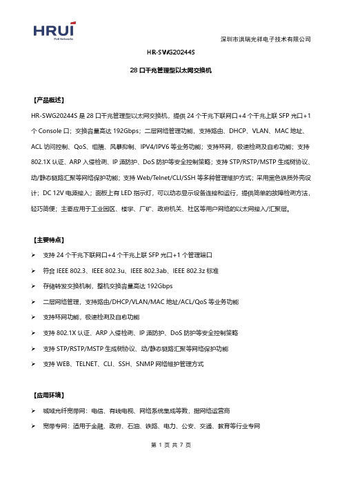
HR-SWG20244S28口千兆管理型以太网交换机【产品概述】HR-SWG20244S是28口千兆管理型以太网交换机,提供24个千兆下联网口+4个千兆上联SFP光口+1个Console口;交换容量高达192Gbps;二层网络管理功能,支持路由、DHCP、VLAN、MAC地址、ACL访问控制、QoS、组播、风暴抑制、IPV4/IPV6等业务功能;支持环网,极速检测及自愈功能;支持802.1X认证、ARP入侵检测、IP源防护、DoS防护等安全控制策略;支持STP/RSTP/MSTP生成树协议、动/静态链路汇聚等网络保护功能;支持Web/Telnet/CLI/SSH等多种管理维护方式;采用黑色铁质外壳设计;DC12V电源接入;面板上有LED指示灯,可以动态显示设备连接和运行,提供简单的故障检测方法,轻巧简便;主要应用于工业园区、楼宇、厂矿、政府机关、社区等用户网络的以太网接入/汇聚层。
【主要特点】支持24个千兆下联网口+4个千兆上联SFP光口+1个管理端口符合IEEE802.3、IEEE802.3u、IEEE802.3ab、IEEE802.3z标准存储转发交换机制,整机交换容量高达192Gbps二层网络管理,支持路由/DHCP/VLAN/MAC地址/ACL/QoS等业务功能支持环网功能,极速检测及自愈功能支持802.1X认证、ARP入侵检测、IP源防护、DoS防护等安全控制策略支持STP/RSTP/MSTP生成树协议、动/静态链路汇聚等网络保护功能支持WEB、TELNET、CLI、SSH、SNMP网络维护管理方式【应用环境】城域光纤宽带网:电信、有线电视、网络系统集成等数,据网络运营商宽带专网:适用于金融、政府、石油、铁路、电力、公安、交通、教育等行业专网多媒体传输:图像、话音、数据综合传输、适用于远程教学、会议电视、可视电话等应用 实时监控:实时控制信号、图像及数据同时传输【技术指标】【订购信息】【产品效果图】。
先锋易讯集团电话交换机 目录说明书
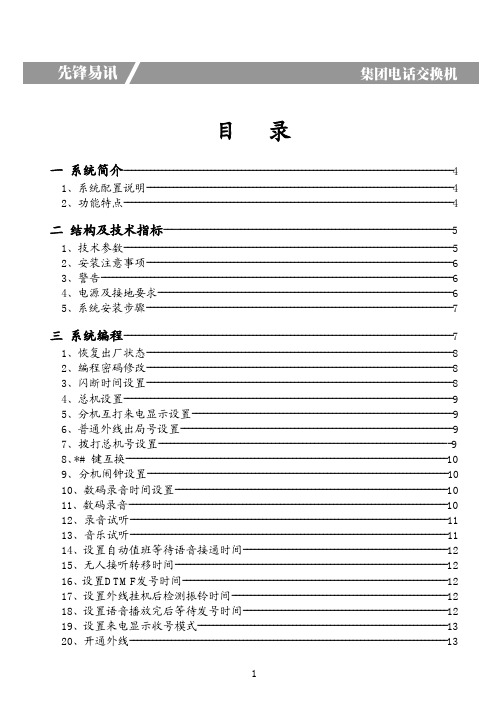
目录一系统简介---------------------------------------------------------------------------------------41、系统配置说明---------------------------------------------------------------------------------42、功能特点---------------------------------------------------------------------------------------4二结构及技术指标----------------------------------------------------------------------------51、技术参数---------------------------------------------------------------------------------------52、安装注意事项---------------------------------------------------------------------------------63、警告---------------------------------------------------------------------------------------------64、电源及接地要求------------------------------------------------------------------------------65、系统安装步骤---------------------------------------------------------------------------------7三系统编程---------------------------------------------------------------------------------------71、恢复出厂状态---------------------------------------------------------------------------------82、编程密码修改---------------------------------------------------------------------------------83、闪断时间设置---------------------------------------------------------------------------------84、总机设置---------------------------------------------------------------------------------------95、分机互打来电显示设置---------------------------------------------------------------------96、普通外线出局号设置------------------------------------------------------------------------97、拨打总机号设置---------------------------------------------------------------------------98、*#键互换-------------------------------------------------------------------------------------109、分机闹钟设置-------------------------------------------------------------------------------1010、数码录音时间设置------------------------------------------------------------------------1011、数码录音------------------------------------------------------------------------------------1012、录音试听------------------------------------------------------------------------------------1113、音乐试听------------------------------------------------------------------------------------1114、设置自动值班等待语音接通时间------------------------------------------------------1215、无人接听转移时间------------------------------------------------------------------------1216、设置DTMF发号时间----------------------------------------------------------------------1217、设置外线挂机后检测振铃时间---------------------------------------------------------1218、设置语音播放完后等待发号时间------------------------------------------------------1219、设置来电显示收号模式------------------------------------------------------------------1320、开通外线------------------------------------------------------------------------------------1321、值班模式-----------------------------------------------------------------------------------1322、设置外线呼入振铃分机-----------------------------------------------------------------1423、外线呼入振铃延时-----------------------------------------------------------------------1424、外线话务量使用分配--------------------------------------------------------------------1525、外线自动值班无拨号处理--------------------------------------------------------------1526、外线呼叫转移无人接听处理-----------------------------------------------------------1527、开关内部呼叫代接功能-----------------------------------------------------------------1528、开关内部通话转移功能-----------------------------------------------------------------1529、排队振铃-----------------------------------------------------------------------------------1530、自动值班拨错号码处理-----------------------------------------------------------------1631、分机出局方式设置-----------------------------------------------------------------------1632、呼出等级限制设置-----------------------------------------------------------------------1633、呼出限时设置-----------------------------------------------------------------------------1734、遇忙、无人接听转移设置--------------------------------------------------------------1735、呼叫无条件转移设置--------------------------------------------------------------------1836、外线使用权限设置-----------------------------------------------------------------------1837、分机号码设置-----------------------------------------------------------------------------1838、呼出限制字头设置-----------------------------------------------------------------------1939、呼出特许字头设置-----------------------------------------------------------------------2040、移动账号-----------------------------------------------------------------------------------2041、计费延时时间设定-----------------------------------------------------------------------2042、清除计费话单-----------------------------------------------------------------------------21四使用方法-------------------------------------------------------------------------------------211、人工值班------------------------------------------------------------------------------------212、自动值班------------------------------------------------------------------------------------213、代接外(内)线---------------------------------------------------------------------------214、拨打外线------------------------------------------------------------------------------------215、预约外线------------------------------------------------------------------------------------216、选择外线------------------------------------------------------------------------------------227、外线转移------------------------------------------------------------------------------------228、拨打内线------------------------------------------------------------------------------------239、三方通话------------------------------------------------------------------------------------2310、外线保留----------------------------------------------------------------------------------2311、拨打总机----------------------------------------------------------------------------------2312、内线转移-----------------------------------------------------------------------------------2313、分机查询功能--------------------------------------------------------------------------------2414、系统日期时间查询功能-------------------------------------------------------------------2415、系统版本查询功能--------------------------------------------------------------------------2416、闹钟使用---------------------------------------------------------------------------------------2517、移动账号使用方法--------------------------------------------------------------------------2518、监听--------------------------------------------------------------------------------------------2519、呼叫无条件转移-----------------------------------------------------------------------------2520、遇忙、无人接听转移-----------------------------------------------------------------------2521、免打扰-----------------------------------------------------------------------------------------2622、群呼(紧急呼叫)--------------------------------------------------------------------------26附录一电话路由选择功能(可选)---------------------------------------------------------26附录二日夜值班功能设置--------------------------------------------------------------------29附录三IP加拨功能-----------------------------------------------------------------------------31附录四外线联号功能--------------------------------------------------------------------------32附录五特色功能--------------------------------------------------------------------------------33附录六IVR多级语音导航功能---------------------------------------------------------------37附录七名称术语--------------------------------------------------------------------------------40附录八出厂默认值-----------------------------------------------------------------------------41附录九系统功能编程指令集-----------------------------------------------------------------42附录十操作使用代码表-----------------------------------------------------------------------45附录十一常见故障及排除--------------------------------------------------------------------46产品质量保证说明------------------------------------------------------------------------------47产品保修卡---------------------------------------------------------------------------------------47一、系统简介1、系统配置说明:本说明书适用于TK8000集团电话(电话交换机)AP、AK、BK等系列,说明书上所列出的功能必须该型号机型支持才可设置,具体请参照功能说明后面标注所支持的机型或产品的配置参数。
销售工程师技能认证教材-chinamanufactur

1端口XENPAK接口,支持XENPAK光口和电口,支持MPLS等功能
2端口XENPAK接口,支持XENPAK光口和电口 2端口XENPAK接口,支持XENPAK光口,支持MPLS等功能 普通POS3(155M OC3)接口板,4端口POS3 SFP光口+4端口千兆SFP光口+4端口千兆光电
用 1000BASE-LX SFP单纤双向B接口(单模10km,TX-1490nm/RX-1310nm,SC接口),A、B需配套使
用 10G XENPAK接口(多模300米/850nm,SC接口)
10G XENPAK接口(单模10km/1310nm,SC接口)
10G XENPAK接口(单模40km/1550nm,SC接口)
可选接口 T160G运行所需操作系统软件,包括IP路由软件(RIPv2、OSPF、BGP),QOS服务软件。
以上业务模块需要根据用户实际需求选择不同业务模块来满足用户需求。 在配置光接口时,需要配置用户实际需求相应的SFP模块或GBIC模块,详细参见以下光器件模块。
交换机配置实例(1)
SFP-FX/OC3-M2K SFP-FX/OC3-S15K SFP-FX/OC3-S40K SFP-FX/OC3-S80K SFP-SDA-FE-S15K SFP-SDB-FE-S15K SFP-GE-RJ45 SFP-GE-M500 SFP-GE-S10K SFP-GE-S40K SFP-GE-S40K-1550 SFP-GE-S80K
销售工程师技能认证教材
——第九章 配置指导书
华为企业交换机渠道销售策略指导手册

适用范围&修订记录
适用范围:适用于全球所有经华为企业业务认证的总经销商、一级经销商(VAP)及二级经销商, 以及所有其他华为客户
修订记录:
录
1销售一指禅 (4)
1.12013交换机版本 (4)
1.2销售策略 (5)
1.3分销策略 (5)
1.4关键场景销售策略 (6)
1.4.1园区场景机会点 (6)
1.4.2传统数据中心场景机会点 (6)
1.4.3政府行业机会点(中国区使用) (7)
1.4.4大企业机会点 (8)
1.4.5金融行业机会点 (8)
2可销售产品 (9)
2.1S X7交换机全景图 (9)
2.2可销售清单及关键亮点 (9)
2.3框式板卡销售状态 (17)
3销售策略 (20)
3.1框式销售策略 (20)
3.1.1框式交换机竞争打法 (20)
3.1.2框式单板场景定位 (20)
3.2千兆盒式交换机定位 (24)
3.3百兆盒式交换机定位 (26)
3.4SMB定位 (27)
4销售约束 (28)
4.1产品销售约束 (28)
4.1.1S9700 (28)
4.1.2S7700 (30)
4.1.3S5700配置注意事项 (32)
4.1.4S3700配置注意事项 (33)
4.1.5S2700配置注意事项 (34)
5附录 (34)
5.1信息获取途径 (34)。
交换机说明书

国威交换机说明书编程,国威交换机说明书下载,国威电话交换机说明书,国威程控交换机的设置,国威集团电话说明书以下编程适用于,ws-824,ws-824(9),ws-848D,ws-16128,WS-3296,ws-32256,ws-288等机型专用话机进入系统编程方法:在挂机(时间显示)状态下,连续按三次检查键,显示屏显示:输入系统密码(系统密码为7位,出厂时为1967590),密码输入正确后,显示屏显示:系统编程状态。
输入项目代码后可进行各分项设置,在光标处可以直接输入分项和相关内容的数字,按转接键可移动光标和转入下一分项。
本项目编程完成后,按保留键,保留内容并退出本项目,可继续进行其他项目编程,所有程序编程完成后,按清除键退出系统编程状态,恢复使用的时间显示状态。
普通话机系统编程进入方法:使用一部音频按键电话,摘机后输入#787+系统密码,密码输入正确后,重新听到拨号音,则进入系统编程。
输入不正确则听忙音。
说明书中*号在不同位置都有不同的意义,有时表示所有的意思,有时表示清除,有时表示空格和转入下一分项,在系统编程中对不同编程项都有具体说明。
系统编程内容及显示屏显示如下:项目(00):日期和时间设置上行显示:日期时间设置下行显示:年:97----年份,输入数字码,两位00--99,输完后按转接键转下一步:月:07----月份,输入数字码,两位0l--12,输完后按转接键转下一步:日:01----日,输入数字码,两位01--31,输完后按转接键转下一步:星期:0一星期,输入数字0-6,0表示星期天,1-6表示星期一至六,输完后按转接键转下一步:小时:00-小时,采用12小时制,输入数字码,两位01--12,输完后按转接键转下一步:分钟:00--分钟,输入数字码,两位00-59,输完后按转接键转下一步:上小午:0--上下午,输入数字码,0表示上午,1表示下午,输完后按转接键又转回年份输入:输入正确后按保留键(即把输入的日期和时间存储),退回到输入项目代码状态。
思科250系列智能交换机快速入门指南说明书
快速入门指南思科 250 系列智能交换机以太网交换机欢迎感谢您选择思科 250 系列智能交换机。
此产品系列作为一种标准交换机,具有开箱即用的特性。
在默认配置下,本产品只需接通电源,即可在连接设备之间转发数据包。
装箱清单•思科 250 系列智能交换机•机架套件•适用于 SG250-08、SG250-08HP 和 SG250-10P 的壁挂式安装套件•电源线或适配器•本快速入门指南•中国 RoHS 合规信息卡•技术支持联系信息•欧盟指令 1999/5/EC 合规信息(仅适用于欧盟 SKU)本指南将为您介绍此交换机的布局,以及在您的网络中部署此交换机的方式。
有关其他信息,请访问/go/250switches。
使用准备1在开始安装之前,请确保您已准备好以下用品:•用于连接网络设备的 RJ-45 以太网电缆(5E 类或更高级别)。
•用于安装硬件的工具。
交换机附带的机架固定套件包含 4 个用于桌面安放的橡胶支脚、2 个支架和 12 个用于机架式安装的螺钉。
如果附带的螺钉遗失,请使用以下尺寸的螺钉作为替代:–螺钉头直径:6.9 毫米–螺钉全长(钉头至钉尖):5.9 毫米–钉身直径:3.94 毫米•壁挂式安装套件包含螺钉和墙锚。
如果附带的螺钉遗失,请使用以下尺寸的螺钉作为替代:–螺钉头直径:6.8 毫米–螺钉全长(钉头至钉尖):16 毫米–钉身直径:3.5 x 1.3 毫米•装有 Microsoft Internet Explorer(版本 9.0、10.0 或 11.0)、Mozilla Firefox(版本 51.0、52.0、53.0 或更高版本)或 Google Chrome(版本56、57、58 或更高版本)的计算机,用于运行基于 Web 的界面。
2思科 250 系列智能交换机安装思科 250 系列智能交换机2本交换机有三种安装方式:•将交换机放置于水平表面。
在交换机底部安装四个橡胶支脚,可将交换机安放于桌面。
2光4电交换机使用说明书

2光4电交换机使用说明书型号:FT2400FE天津滨海新区三格电子科技有限公司一、概述本产品为带光口的交换机,在传统的五类六类线网络只有一百米的数据传输覆盖区域的基础上,本产品所带的光口可以将数据通过光口传输,以将数据传输范围扩展到千米的级别,最大的覆盖范围为25千米,具有一般的只有电口的交换机不具有的远距数据传输的优良特性。
短距离和长距离的数据传输范围的组合选择,使网络数据的传输的范围大小配置更为灵活。
还可与本公司的双纤双向100M光纤收发器配合使用,组网更为方便。
二、规格与特性标准:IEEE802.3az EEE,IEEE802.3,IEEE802.3u, IEEE802.3x100Base-FX,100Base-TX接口:电口,RJ45;光口,SC。
传输速率:光口155Mbps;电口10/100Mbps自适应。
光口:全双工距离:25KM电口:全双工/半双工网线:五类双绞线。
光纤:SC口,单模,双纤,1310nm。
电源:直流5V,1A。
附带节能方式:无连接时将自动进入省电模式,有连接但无数据会自动进入节电模式。
环境温度:-20---70°C存储温度:-65---150°C湿度:5%---90%三、安装方法1、连接光纤,光纤需要交叉连接,交换机光口A的RX接收发器(可以是交换机光口)B的TX,交换机光口A的TX接收发器(可以是交换机光口)B的RX。
2、接网线,网线可以是直连型,也可以是交叉型,电口可以自适应两种网线,可与其他的交换机相接。
注意:网线不能和其他的交换机构成环路。
3、上电。
四、LED指示灯Pow/off:板卡工作电源和耗能指示灯,在正常工作状态下灯亮,在强制掉电下灯灭;Fiber0、Fiber1:灯亮且长周期性闪烁表示光口有连接且连接成功,灯灭表示无连接或者连接失败;短周期性闪烁表示有数据正在传输。
TP0、TP1、TP2、TP3:灯亮且长周期性闪烁表示电口连接且连接成功,灯灭表示无连接或者连接失败;短周期性闪烁表示有数据正在传输。
TCLAF416集团电话交换机说明书

TCLAF416集团电话交换机说明书第一篇:TCLAF416集团电话交换机说明书TCLAF416集团电话交换机说明书注意事项(一)安装注意事项,诮仔细阅读:1、注意事项①本机应安装在干燥、通风、平稳、牢固的室内地方(温度范围:0℃-45℃而湿度20%—80%,避免置于太阳直射或含有可燃性气体腐蚀之场所),布线时最好使用专用电话线与本机连接。
②安装位置必须有一定的空间,以保证系统的散热及系统的检查及维护。
⑧主机底面有挂墙孔,可挂墙亦可台放安装,避免挂墙螺钉与机内线路板接触。
④请勿将交换机与其它产生大电磁干扰源的设备(如马达、大变压器等)放置在一起。
⑤所有分机配线必须避免与电源线或天线同管路,避免接近收音广播天线(包括短波)。
⑥避免损坏电源电缆,避免水溅雨淋,如有水进入机内,立即断电确保安全。
⑦请勿对交换机施加冲击和震动及随意移动使用中的交换机。
⑧如果分机配线管路遭受电磁波干扰,因现场限制无法更换通路时,建议采用通信专用隔离线架设备,并将隔离网一端接地处理。
ATTENTION:雷击系属于意外事件,不在正常保修范围。
ATTENTION:在雷电期间,不要进行电话线路的连接工作。
在雷电期间,尽量避免使用电话。
请勿在汇漏易燃气体的现场附近使用电话。
除非电话与设备处于分离状态,否则不要触及电话软线的破损或接线端子部分。
人工值班一、呼入人工值班是指当有外线呼入时,已设成值班的分机将响铃,提响铃的分机即可接通外线的工作方式。
人工值班特别适合有专人值班的场合。
例如:ATTENTION:在人工值班时,响铃分机提机便可立即接通外线,若没响铃的分机提机希望接进该呼叫,则只有通过“代接”功能来实现。
电脑值班电脑话务员方式对子没有专人值班的公司、工厂来说是非常实用的一个功能,它能让外线直拨某一分机,又可通过值班小姐帮助接入,并能提高公司形象。
例如;先录入话务员提示信息:您好,中国xxx电子通讯,请拨分机号码,经理“601”、总机“602”’、传真“610”、查号请拨“0”。
ICG销售指导书200804
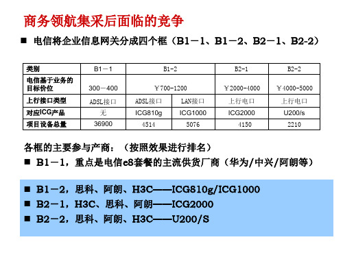
B2-1
¥2000-4000 上行电口 ICG2000 4150
B2-2
¥4000-5000 上行电口 U200/s 2210
各框的主要参与产商:(按照效果进行排名) B1-1,重点是电信e8套餐的主流供货厂商(华为/中兴/阿朗等)
B1-2,思科、阿朗、H3C——ICG810g/ICG1000 B2-1,H3C、思科、阿朗——ICG2000 B2-2,思科、阿朗、H3C——U200/S
机会点二:聚类行业模式的策略总结
产品规划:
•开发ICG1800,满足网吧、酒店等市场行业联盟的要求 •完善ICG1000以上产品的集中式管理(如TR069和SNMP开发需要)
产品策略
•网吧市场推广四川蓝海网盟模式,产品组合ICG1000+ICG1800 •酒店市场推广酒店式解决方案,产品组合ICG1800/ICG2000 •普教市场推广四川金色校园模式,产品组合ICG3000+OAP模式(裸板) •区县政府信息化市场推广区县政府解决方案,产品组合 ICG2000/ICG3000+OAP模式;(4月份明确打法后再定)
100用户企业Βιβλιοθήκη ICG 5000+
ICG 3000
OAP板卡
ICG 2000
ICG 1000
ICG 1800
H3C对于企业市场积累决定该市场的产品优势
场合:面向学校、政 府等需要提供增值服 务(UC、校园软件等) 的市场 竞争:本地一些工控 机+软件的个性化对 手
场合:面向网吧、酒店 等市场形成行业联盟, 或者转售型市场 竞争:主要面向个性化 本地产商竞争,引导空 间非常大
制, 目前没有竞争对手。
ICG产品族(不含ICG7000)
300-500 用户企业
Gefen 4x1 DVI DL 交换机用户指南说明书
ASKING FOR ASSISTANCETechnical Support:Telephone (818)772-9100(800)545-6900772-9120Fax(818)Technical Support Hours:8:00 AM to 5:00 PM Monday through Friday.Write To:Gefen Inc.c/o Customer Service20600 Nordhoff StChatsworth, CA 91311*****************NoticeGefen Inc. reserves the right to make changes in the hard w are, packaging and any accompanying doc u m en t a t ion without prior written notice.4x1 DVI DL Switcher is a trademark of Gefen Inc.© 2007 Gefen Inc., All Rights ReservedTABLE OF CONTENTSIntroduction FeaturesPanel DescriptionsConnecting and Operating the 4x1 DVI DL Switcher RMT4-IR Installation Dip Switch GuideOperation Notes & Troubleshooting RS-232 Interface Speci fi cations Warranty12345678910INTRODUCTIONCongratulations on your purchase of the 4x1 DVI DL Switcher. Your complete satisfac-tion is very important to us.Gefen’s line of KVM (Keyboard Video & Mouse), DVI, ADC, USB, switches, extenders, converters and hubs is designed to make computer use more comfortable, more pro-ductive and less expensive. KVM switches allow access to multiple computers from a single keyboard, while the extenders give the user control over a computer up to 330 feet away from the work area. The ex•tend•it line offers solutions for noise, space and security concerns, data center control, information distribution, conference room presen-tation, and school and corporate training environments.Our CommitmentGefen will always offer the fi nest quality product at the best possible price. Included in that price is a lifetime of free support from a team of outstanding engineers.Now you can switch easily and reliably between any combination of four dual link DVI& USB 2.0 equipped computers (PC or Mac) - using only one keyboard, display and mouse. The DL cross platform switcher saves space - there’s no need to work on a desk crowded with double displays, keyboards and mouse devices. It saves time - there’s no need to move from one monitor to another to access different computers. And, it saves money - there’s no need to purchase additional displays, mouse devices, keyboards etc.FEATURESFeatures• Switches easily between any four dual link DVI computers with USB 2.0 and audio • Maintains highest 3840 x 2400 resolution dual link video• Saves you money on hardware costs• Use either PC or Mac USB 2.0 keyboard/mouse• Discrete IR remote (included)• RS-232 remote port• Supports DDWG standards for DVI monitors• Installs in minutes• Includes Rack EarsIncludes:(1) 4x1 DVI DL Switcher(1) 5V DC Power Supply(1) RMT4-IR Remote Control(4) 6ft Dual Link DVI cables(4) 6ft USB cables(4) Audio Cables(1) Set of Rack EarsPANEL DESCRIPTIONSP o w e r I n d i c a t o rI n f r a r e d S e n s o rI n d i c a t e s w h i c h i n p u t i s s e l e c t e dR S -232 I n t e r f a c e5V D C I n p u tD V I I n 1D V I I n 2D V I O u t U S B O u t p u t s D V I I n 3D V I I n 4U S B I n p u t s I RE x t e n d e r P o r tB u t t o n s t o s e l e c t i n p u t s 1 t h r o u g h 4A u d i o O u t A u d i o I n 4A u d i o I n 3A u d i o I n 2A u d i o I n 1CONNECTING AND OPERATING THE 4x1 DVI DL SWITCHER How to Connect the 4x1 DVI DL Switcher to your devices1- Connect the supplied cables from your fi rst computer into the DVI In 1, USB In 1, and Audio In 1 connection in the back of the DVI Switcher.2- Repeat step one for up to four computers on inputs 2-4.3- Connect the monitor to the DVI Out connection.4- Connect your USB devices (e.g. keyboard, mouse) into the USB Out.5- Connect your speakers to the Audio Out.6- Plug the 5VDC power supply into the 4x1 DVI DL Switcher.How to Operate the 4x1 DVI DL Switcher1- Use the RMT4-IR remote control port to remotely switch between sources.2- Use the RS-232 interface with a compliant device to switch between sources.RMT4-IR INSTALLATION1. Remove battery cover from the back of the RMT4-IR remote.2. Verify that dip switches 1 & 2 are in the down (OFF) position.3. Insert the battery, hold the battery so that you can see the positive side facing up. The side that is not marked must be facing down.4. Test the RMT4-IR remote by pressing ONLY one button at a time. The indicator light on the remote will fl ash once each time you press a button. WARNING: Do not press multiple buttons simultaneously and do NOT press buttons rapidly. These actions will cause the remote to reset and steps 1-4 will have to be repeated.Note: The RMT4-IR ships with two batteries. One battery is required for operation, the second battery is complimentary.How to Operate the IR Extender Eye (optional)Plug in the IR extender eye to the extender port on the back of the switcher. As soon as the IR extender eye is plugged in you can extend your IR signal. The IR extender eye does not come included in the package.DIP SWITCH GUIDEif you are experiencing Infrared interference, you can change the IR code on the Re-mote and the 4x1 DVI DL Switcher itself.To change the IR code on the RMT4-IR, simply remove the battery cover and fi nd the 2 dip switches just above the batteries. These switches correspond to a set of switches on the 4x1 DVI DL Switcher.To change the IR code on the 4x1 DVI DL Switcher, look under the unit and fi nd a silver sticker. Beneath this sticker is a group of 4 dip switches. The fi rst 2 switches (labelled 1 and 2) correspond to the 2 switches found on the RMT4-IR remote control.The following are the 4 Infrared channels possible for both the RMT4-IR and the4x1 DVI DL Switcher. The dip switches on both the remote and the switcher itself must match in order to be operational.12Channel 0:12Channel 1:12Channel 2:12Channel 3:OPERATION NOTES & TROUBLESHOOTINGUSBIf your USB stops functioning correctly, you can manually re-initialize the USB hub in the switch by pushing twice on the channel select button, that corresponds with the channel that the switcher is pointed at, on the front of the unit. This will cause the channel selected LED to blink once letting you know the USB hub has beenre-initialized.To have the USB re-initialize automatically every time you switch, look under the 4x1 DVI Switcher and locate the blank sticker. Peel it off to reveal a bank of four dip switch-es. Find the dip switch labeled “4” and fl ip it to the ON position. Now every time you switch the hub will re-initialize itself.VideoWhen turning on or rebooting your computers, the 4x1 DVI DL Switcher must be se-lected to the computer that is booting until the computer completes the boot cycle. This step can be eliminated using the Gefen DVI Detective.If you loose your picture when you switch between sources you will need a DVI Detective.To switch between Dual Link and Single Link sources, a Single Link cable (sold separately) must be used for each Single Link source connected to the switcher.RS-232 INTERFACEBinary TableBinaryASCII CorrespondingRMT4-IRButton110011 0001220011 0010330011 0011440011 0100RS-232 SettingsBits per second (19200)Data bits (8)Parity ....................................................................................................................... NoneStop bits (1)Flow Control ............................................................................................................ NoneSPECIFICATIONSVideo Amplifi er Bandwidth ........................................................................... 2x 1.65 Gbps Input Video Signals ....................................................................................... 1.2 volts p-p Input DDC Signal .................................................................................... 5 volts p-p (TTL) Dual Link Range ......................................................................................... 3840 x 2400 DVI Input/Output Connector Type ............................................ DVI-I (only digital signals) USB 2.0 Input Connection ................................................................................... Type “B” USB 2.0 Output Connection ................................................................................ Type “A” Power Consumption ................................................................................. 20 watts (max) Power Supply ......................................................................................................... 5V DC Dimensions ............................................................................ 17” W x 1.75” H x 4.375” D Rackmountable ........................................................................................... 1 Rack Space Shipping Weight ....................................................................................................... 8 lbs.WARRANTYGefen Inc. warrants the equipment it manufactures to be free from defects in material and workmanship.If equipment fails because of such defects and Gefen Inc. is notifi ed within two(2) year from the date of shipment, Gefen Inc. will, at its option, repair or replacethe equipment, provided that the equipment has not been subjected to mechanical, electrical, or other abuse or modifi cations.Equipment that fails under conditions other than those covered will be repaired at the current price of parts and labor in effect at the time of repair. Such repairs are warranted for ninety (90) days from the day of reshipment to the Buyer.This warranty is in lieu of all other warranties expressed or implied, including without limitation, any implied warranty or merchantability or fi tness for any particular purpose, all of which are expressly disclaimed.1. Proof of sale may be required in order to claim warranty.2. Customers outside the US are responsible for shipping charges to and from Gefen.3. Copper cables are limited to a 30 day warranty and cable must be free from anyscratches, markings, and neatly coiled.The information in this manual has been carefully checked and is believed to be accurate. However, Gefen Inc. assumes no responsibility for any inaccuracies that may be contained in this manual. In no event will Gefen Inc., be liable for direct, indirect, special, incidental, or consequential damages resulting from any defect or omissionin this manual, even if advised of the possibility of such damages. The technical information contained herein regarding 4x1 DVI DL Switcher features and specifi cations is subject to change without notice.。
精编-中低端路由器销售指导书

一、H3C中低端路由器应用场景二、H3C中低端路由器测试情况分析✧ICG3000和ICG2000(B类设备)本次集采招标综合排名第三,仅次于华为和中兴。
思科排名第四;在技术部分,H3C中低端路由器排名高于华为和中兴;但在价格部分,华为和中兴比我司有竞争力;在省市电信可以重点突出我司产品的功能。
✧ICG系列产品和电信商务领航定制网关的区别主要如下:ICG系列网关主要定位在运营商市场(包括内部网和转售市场);Navigator系列主要定位在电信商务领航企业网关市场,它对设备的外观、界面和预配置都有严格的要求。
本次IP5类招标的设备都是属于ICG系列,而非Navigator系列网关。
三、H3C中低端路由器产品系列简介✧边缘接入型路由器(ICG2000):应用于20-100个信息点的中小企业、小型分支机构、连锁店等。
✧多业务接入型路由器(ICG3000):应用于100-300个信息点的中型分支节点的接入,支持路由交换一体化、信息和通信业务的融合。
✧边界出口型路由器(ICG5000):应用于大中型企业网络出口路由器。
支持高性能、多业务的一体化处理能力。
✧多业务汇聚型路由器(SR 6608):应用于大型网络的高性能汇聚和接入设备,单FIP板处理能力7.5Mpps,整机处理性能30Mpps。
四、H3C中低端路由器-ICG系列路由器1、拜访用户时传递的信息✧多业务网关之-业界领先的体系架构H3C ICG系列路由器采用先进的N-BUS多总线架构,语音、数据、交换、安全四大业务分别经由不同的总线,由专门的协处理引擎并行处理,消除总线和CPU性能瓶颈,是同类AR产品性能的2倍,是真正的新一代多业务网关。
ICG系列网关在性能上相对于友商同类产品有优势。
✧多业务网关之-基于硬件的安全特性ICG系列基于N-BUS多总线架构,提供基于硬件的安全特性:⏹强大的内置防火墙功能,支持包过滤及状态防火墙;⏹主机内置硬件加密引擎,提供SSL、IPSec、GRE、MPLS L2/L3、L2TP及DVPN等VPN接入方式;⏹支持基于硬件的防病毒功能,使用户对病毒从被动变为网关处主动防御;✧多业务网关之-语音特性ICG系列产品采用全新的硬件语音设计方案,提供FXS/FXO/VE1/VT1等各种语音接口类型,支持H.323、SIP等主流的语音通讯协议,可实现紧急呼叫/掉电求救/拨号策略/传真/E-PHONE等各种语音业务。
C64-SecPath 防火墙销售指导书

电信集采H3C SecPath 防火墙/VPN销售指导书本次集采防火墙主要的应用场景:•OA、DCN支撑系统安全加固•IDC安全•VPN 安全网关应用•新业务系统安全配套•3G核心网互联网出口安全拜访客户时需要传递什么信息?FW特色☑性能最高〔H3C安全能提供最强的万兆、超万兆防火墙,性能业内第一〕;☑业务创新〔H3C安全创新的将防病毒、流量监控和SSL VPN等业务功能,通过OAA架构合入防火墙产品,为用户提供多业务融合的安全防护,是业内唯一全面提供硬件扩展的公司〕;☑支持IPV6〔为满足网络发展需要,H3C防火墙支持IPV6协议,符合技术发展趋势,保护用户网络切换成本〕;☑国内率先通过RoHS认证〔通过欧洲最严格的环保认证,在产品的功耗、辐射和回收等方面进行专业设计,让用户放心使用,符合国家绿色发展方向〕;UTM特色☑多核,UTM最佳平台〔H3C 首创多核多线程硬件平台,完美的解决了UTM多功能开启时性能急剧下降的难题,为用户提供真正的高性能的UTM产品。
☑细流控,国内P2P控制最全、最细的UTM〔H3C 提供对国内P2P协议的最细致(8K)、最全面(迅雷、QQ),保障网络中核心业务正常运行。
〕;☑全审计,唯一支持用户行为全面监控的UTM〔H3C 首创UTM针对应用层的行为审计,完全符合公安部82令,规范网络用户行为〕;☑易管理,率先集成TR069的UTM〔H3C 首创UTM集成TR069协议,保障海量设备的远程集中管理〕;☑支持IPV6〔H3C UTM支持IPV6协议,符合技术发展趋势,保护用户网络切换成本〕;☑国内率先通过RoHS认证〔通过欧洲最严格的环保认证,在产品的功耗、辐射和回收等方面进行专业设计,让用户放心使用,符合国家绿色发展方向〕;我们有什么可卖?H3C SecPath多功能合一:攻击防范、VPN、NAT和虚拟防火墙等功能,满足用户安全需求。
主要用于OA、DCN、IDC、城域网、骨干网、增值业务等。
C63-Navigator系列产品销售指导书(企业网关)

H3C Navigator系列产品销售指导一、拜访用户时传递的信息1、高性能高品质的定制网关:✧Navigator系列产品(包括1-2和2-1)都采用了专业的网络处理器,其数据转发能力不仅远超过电信规范要求,同时也远远领先于友商同类产品。
✧电信研究院的前期入围测试中,Navigator1-2的小包(64Byte)转发性能达到40Mbps以上,Navigator2-1系列产品的转发性能在60Mbps以上。
在所有参测厂商中排名第一。
✧Navigator系列产品采用专业的硬件芯片,电信级工业设计,满足国内复杂环境使用。
通过高品质产品减低中国电信整体部署TCO,降低电信的运维压力和成本。
2、创新支持3G EVDO的能力✧Navigator系列产品创新的支持3G无线上网卡,在“商务领航”引入移动元素,促进与“天翼”的融合,用户可以通过WLAN接入3G网络,上联到移动网络的应用平台,轻松解决了布线的问题。
✧Navigator系列产品的WLAN可以作为城市无线热点部署的补充,其公网SSID和企业内网的SSID可以分别满足公共用户和企业用户的无线接入。
Navigator产品无线热点业务部署配置.do3、强大的VPN安全互连能力✧Navigator系列产品支持点对点的VPN接入(IPSEC VPN/MPLS VPN)和远程VPN接入(SSL VPN),既可保证企业总部和分支之间私有数据的安全传输,同时也可满足企业出差员工移动办公的需要。
✧Navigator1-2产品在IPSEC的性能达到15Mbps,Navigator2-1的性能可以达到30Mbps,其SSL VPN允许接入的客户端为5个。
4、完善的售后服务支撑体系✧H3C组建了独立的企业网关服务团队。
设立杭州、北京2个服务总部,35个区域服务中心,82个备件库;提供7*24小时热线服务,面向中国电信大客户经理和最终客户开展全面的培训。
H3C全力配合中国电信20个重点本地网“商务领航定制终端组合方案市场推广”活动,08年与中国电信一起共同参加了杭州、福州、青岛、长沙、乌鲁木齐等13站的拓展。
cisco产品手册
Cisco产品销售手册CISCO SystemsCisco Systems, Inc. is the worldwide leader in networking for the Inte rnet. Cisco routers are the basis for over 80% of the Internet infras tructure, and Cisco supplies 60% of the access solutions used by compa nies to provide connectivity for remote users and connectivity to the Internet. Additionally, Cisco, the inventor of switched Ethernet and Fast Ethernet -- today's most popular high-performance LAN technologie s -- leads the way in providing affordable, high performance LAN solut ions.Cisco's solutions designed for small and medium-sized businesses help you maximize your business potential and cost-effectively meet your ex panding networking requirements. These solutions leverage Cisco's vas t networking experience, innovative technologies, outstanding service, and high-quality products; and they help organizations make the trans ition from today's shared 10BaseT networks to high performance network s that extend beyond the main office to branch offices, mobile users a nd telecommuters, and to the Internet. These solutions give network m anagers the tools they need to build networks that are scaleable, flex ible, and powerful enough to handle the challenges of today's business environment.Cisco products include a wide range of high performance LAN products s uch as 100BaseT hubs and Ethernet switches, routers, dial access serve rs and network management software solutions. All of these products a re based on the Cisco Internetwork Operating System (Cisco IOS? technologies -- an integrated suite of network services that provides the na tive intelligence for more than one million installed Cisco units, as well as comprising an integral part of the products of many global par tners. All Cisco products provide quality, reliability, network secur ity and interoperability based on industry standards.Headquartered in San Jose, California, Cisco employs more than 9000 pe ople in over 125 worldwide locations. The company’s stock is traded over the counter on the Nasdaq National Market under the symbol "CSCO". Cisco Systems美国Cisco系统公司是世界上占领先地位的网间网互联技术和产品的供应商,一直掌握着计算机网络互联系统全球市场的50%以上。
Juniper交换机中文操作手册(完整版)V1.0

Juniper EX 系列以太网交换机操作手册Version 1.0Copyright © 2008 Juniper Networks, Inc.Juniper EX系列以太网交换机操作手册Juniper EX系列以太网交换机操作手册Juniper EX系列以太网交换机操作手册Juniper EX系列以太网交换机操作手册Juniper EX系列以太网交换机操作手册Juniper EX系列以太网交换机操作手册Juniper EX系列以太网交换机操作手册Juniper EX系列以太网交换机操作手册Juniper EX系列以太网交换机操作手册Juniper EX系列以太网交换机操作手册Juniper EX系列以太网交换机操作手册Juniper EX系列以太网交换机操作手册Juniper EX系列以太网交换机操作手册Juniper EX系列以太网交换机操作手册Juniper EX系列以太网交换机操作手册Juniper EX系列以太网交换机操作手册Juniper EX系列以太网交换机操作手册Juniper EX系列以太网交换机操作手册Juniper EX系列以太网交换机操作手册Juniper EX系列以太网交换机操作手册Juniper EX系列以太网交换机操作手册Juniper EX系列以太网交换机操作手册Juniper EX系列以太网交换机操作手册Juniper EX系列以太网交换机操作手册Juniper EX系列以太网交换机操作手册Juniper EX系列以太网交换机操作手册Juniper EX系列以太网交换机操作手册Juniper EX系列以太网交换机操作手册Juniper EX系列以太网交换机操作手册Juniper EX系列以太网交换机操作手册Juniper EX系列以太网交换机操作手册Juniper EX系列以太网交换机操作手册Juniper EX系列以太网交换机操作手册Juniper EX系列以太网交换机操作手册Juniper EX系列以太网交换机操作手册Juniper EX系列以太网交换机操作手册Juniper EX系列以太网交换机操作手册Juniper EX系列以太网交换机操作手册Juniper EX系列以太网交换机操作手册Juniper EX系列以太网交换机操作手册Juniper EX系列以太网交换机操作手册Juniper EX系列以太网交换机操作手册Juniper EX系列以太网交换机操作手册Juniper EX系列以太网交换机操作手册Juniper EX系列以太网交换机操作手册Juniper EX系列以太网交换机操作手册Juniper EX系列以太网交换机操作手册Juniper EX系列以太网交换机操作手册Juniper EX系列以太网交换机操作手册。
六网(Sixnet)未管理工业以太网交换机系列数据手册说明书

SL & SLX Unmanaged Industrial Ethernet SwitchesSixnet Networking SeriesUNMANAGED INDUSTRIAL ETHERNET SWITCHESPRODUCT HIGHLIGHTSnSlim packaging fits on your Din-rail nHigh performance and value nTruly industrial hardened design nPlug & play saves you time and moneyREAL-TIME ETHERNET PERFORMANCEnFast wire-speed switchingnIntelligent message routing - No collisions!nIdeal for any systemPLUG & PLAY SIMPLICITYnAuto-sensing for speed and duplexnAuto-mdi/mdix-crossover works with straight or crossed cablesnAuto-polarity corrects for crossed signalsTROUBLE FREE OPERATIONnUltra-reliable 1,000,000+ hours MTBFnDual power inputs with industrial spike protection nDIN-rail or direct panel mountingnUL/CSA (CUL), CE, hazardous locations (Zone 2) and maritime ratedn-40 to 85°C operating range (SLX models)The SL/SLX-5ES and SL/SLX-8/9ES are 5 and 8/9 port industrial Ethernet switches that provide advanced performance that enables you to achieve real-time deterministic operation. These ruggedized switches are hardened to provide superior reliability. They require no user setup and immediately start operating as soon as you power them up. Sixnet switches are designed to make your job easier, ensuring your system will keeprunning for many years to come.SLX ModelsSL Models Sixnet Knows IndustrialWe have been designing industrial hardware such as Remote Terminal Units for over 30 years and have used this expertise to design the toughest Ethernet switches on the market. Don’t trust your critical communications to so-called industrial hardware from commercial switch manufacturers. Sixnet switches give you proven assurance that your system will keep running for years to come.All specifications are subject to change. Consult factory for latest info.ETHERNET PERFORMANCEn Unmanaged with 5, 8 or 9 Ethernet ports n Store & forward wire-speed switchingn Automatic address learning, aging and migration n Full duplex operation with flow control (no collisions)n All IEEE 802.3 Ethernet protocols supported n 1024 MAC addresses supported n Memory bandwidth 3.2 Gbps nTypical latency (varies on load) p @ 100 Mbps: 5 µs + frame timep @ 10 Mbps: 16 µs + frame timenEthernet isolation 1500 VRMS 1 minute ETHERNET PORTSnShielded RJ45 ports for 10/100BaseTX p Auto-negotiation for 10 or 100 Mbpsp Auto- MDI/MDIX-crossover for either cable typep Auto-polarity corrects for crossed +/- signalsn Fiber optic port speed 100BaseFX (100 Mbps)n Fiber duplex operation: Full duplex n Fiber wavelength: 1300 nm center (typical)nFiber max. distance (full duplex) (see web for details) p 4 km for multimode 50 or 62.5/125 µm (SC or ST) p 20 km for singlemode 9 or 10/125 µm (SC or ST)p 40 km (long haul) or more (contact Sixnet)ETHERNET COMPLIANCEn IEEE 802.3 (10Mbps Ethernet supports legacy devices)n IEEE 802.3u (Fast Ethernet 100Mbps for newer devices)nIEEE 802.3x (Full-Duplex with Flow Control)POWER INPUTn Power input voltage: 10-30 VDC n Redundant input terminalsnInput power (typical - all ports active at 100 Mbps)p 2.0 W (5-port without fiber) p 3.0 W (5-port including 1 fiber) p 4.0 W (8-port without fiber)p 5.0 W (9-port including 1 fiber)n Transient protection: 15,000 watts peaknSpike protection: 5,000 watts (10 times for 10 uS)ENVIRONMENTALnOperating temperaturep SL models: -40 to +60°Cp SLX models: -40 to +85°C (cold startup at -40)n Storage temperature: -40 to +85 °C n Humidity (non-condensing) 5 to 95% RH n Vibration and shock: IEC60068-2-6nMaximum Operating Altitude: 30,000 ft. (SLX models)MECHANICAL DRAWINGSSTANDARDS COMPLIANCEn Electrical safety - UL508/CSA C22.2/142, EN61010-1, CE n EMC - FCC part 15, ICES-003, EN61000-6, CEn Hazardous locations: ANSI/ISA 12.12.01/CSA C22.2/213 (Class I, Div. 2); EN60079-15 (Zone 2, Category 3), CE (ATEX)n Maritime rated for marine & offshore per ABSnEye safety (fiber models) - IEC60825-1, Class 1; FDA 21 CFR 1040.10 and 1040.11PHYSICALn Din-rail or direct panel mounting nIngress protection: p SL models: IP30p SLX models: IP40n Case: UL94V0 Lexan (SL) or Aluminum (SLX)nWeight: p 4 oz (0.11 kg) – SL-5ESp 6 oz (0.17 kg) – SLX-5ES, SL-8/9ESp 8 oz (0.23 kg) – SLX-8/9ESnDimensions – see mechanical diagram belowORDERING GUIDE SLX-5ES-15 RJ45 10/100 portsSLX-5ES-2SC 4 RJ45 ports and 1 mm fiber SC, 4 Km SLX-5ES-2ST 4 RJ45 ports and 1 mm fiber ST, 4 Km SLX-5ES-3SC 4 RJ45 ports and 1 sm fiber SC, 20 Km SLX-5ES-3ST 4 RJ45 ports and 1 sm fiber ST, 20 Km SLX-6ES-4/5 Dual fiber - see separate datasheet SLX-8ES-1 8 RJ45 10/100 portsSLX-8ES-6/7Three fiber - see separate datasheetSLX-9ES-2SC 8 RJ45 ports and 1 mm fiber SC, 4 Km SLX-9ES-2ST 8 RJ45 ports and 1 mm fiber ST, 4 Km SLX-9ES-3SC 8 RJ45 ports and 1 sm fiber SC, 20 Km SLX-9ES-3ST 8 RJ45 ports and 1 sm fiber ST, 20 Km SL- w/Lexan case and limited temperature ET-PS-024-02 2 Amp, AC to 24 VDC Power SupplySP-ETH-2Dual Ethernet port surge & lightning protectorContact Sixnet for special or long haul fiber transeivers up to 120 Km.w w w.r e d l i o n.n e tConnect. Monitor. Control.Americas *****************Asia-Pacific ****************EuropeMiddle East Africa******************+1 (717) 767-6511As the glob al experts in communication, monitoring and control for industrial automation and networking, Red Lion has b een delivering innovative solutions for over forty years. Our automation, Ethernet and cellular M2M technology enables companies worldwide to gain real-time data visib ility that drives productivity. Product b rands include Red Lion, N-Tron and Sixnet. With headquarters in York, Pennsylvania, the company has offices across the Americas, Asia-Pacific and Europe. Red Lion is part of Spectris plc, the productivity-enhancing instrumentation and controls company. For more information, please visit .ADLD0203 091916 © 2016 Red Lion Controls, Inc. All rights reserved. Red Lion, the Red Lion logo, N-Tron and Sixnet are registered trademarks of Red Lion Controls, Inc. All other company and product names are trademarks of their respective owners.。
2024年新款交换机销售协议细则

20XX 标准合同模板范本PERSONAL RESUME甲方:XXX乙方:XXX2024年新款交换机销售协议细则本合同目录一览第一条:合同主体与定义1.1 甲方名称与地址1.2 乙方名称与地址1.3 甲方产品的定义第二条:产品销售2.1 产品规格与型号2.2 销售数量与价格2.3 付款方式与期限第三条:产品交付3.1 交付时间与地点3.2 运输方式与风险承担3.3 验收标准与流程第四条:质量保证4.1 产品质量标准4.2 质量问题的处理4.3 售后服务与保修政策第五条:知识产权5.1 产品知识产权归属5.2 乙方使用与宣传限制第六条:违约责任6.1 甲方违约责任6.2 乙方违约责任第七条:争议解决7.1 争议解决方式7.2 适用法律与管辖第八条:合同的变更与终止8.1 合同变更条件8.2 合同终止条件第九条:保密条款9.1 保密内容与范围9.2 保密期限与违约责任第十条:不可抗力10.1 不可抗力事件10.2 不可抗力事件的处理第十一条:合同的生效与解除11.1 合同生效条件11.2 合同解除条件第十二条:其他条款12.1 信息保密与通知12.2 法律、法规与习俗第十三条:附件13.1 产品清单13.2 技术参数13.3 付款凭证与发票第十四条:签署14.1 甲方代表签字14.2 乙方代表签字14.3 合同日期第一部分:合同如下:第一条:合同主体与定义1.1 甲方名称与地址甲方名称:科技有限公司甲方地址:市区路号1.2 乙方名称与地址乙方名称:网络技术有限公司乙方地址:市区路号1.3 甲方产品的定义甲方产品指的是甲方生产的2024年新款交换机,包括但不限于型号A、型号B、型号C等。
第二条:产品销售2.1 产品规格与型号甲方根据乙方的订单需求,向乙方提供新款交换机的具体型号和规格。
2.2 销售数量与价格乙方订购的甲方新款交换机数量及单价详见附件中的产品清单。
2.3 付款方式与期限乙方采取预付款方式,在合同签订后的五个工作日内将款项支付给甲方。
S6016-CG-W和S6024-CG-W POE交换机用户手册说明书
PoE switches:User Manual S6016-CG-W POE (270W)S6024-CG-W POE (390W)PrefaceThe user manual mainly introduces the product appearance, specification, hardware installation, Web management and other related information.Illustration(1)) F ormat of Graphics Interface(2)) Various SignsContent1 Product Introduction1 1.1 Overview1 1.2 Product Feature 1 1.3 Board Diagram 2 1.4 Specification 3 2 Installation4 2.1 Shipping List4 2.2 Installation Precautions4 2.2.1 Safety Precautions4 2.2.2 Installation Requirements5 2.2.3 The Requirements of Electromagnetic Environment 5 2.3 Installation Way6 2.3.1 Rack Installation6 2.3.2 Workbench Installation7 2.3.3 Wall-hung Installation 7 2.4 Cable Connection8 2.4.1 Device Connection8 2.4.2 Configuration Cable Connection 8 2.4.3 Power Line Connection8 3 PoE Web Management Page9 3.1 Preparation Work9 3.2 Set up Network Connection9 3.2.1 Set Stastic IP Address of Managed PC9 3.2.2 Confirm the Network Connection by Ping Command 11 3.2.3 Cancel the Proxy Server 11 3.3 Operating Guidance of Web12 3.3.1 Start and Login12 3.3.2 Operating Instruction of Web 14 3.4 Typical Application 22 3.5 Troubleshooting221 Product Introduction1.1 OverviewThe 16/24 ports PoE switch is an unmanaged PoE Ethernet switch along with 16/24 * 100Base-TX downlink PoE ports and 2 * 1000Base-TX uplink Ethernet ports featuring 30-watt 802.3at PoE+ as well as 1 additional Gigabit Combo1.3 Board Diagram24 Ports Po E switchPoE Output CCTVResetUplink port. The total PoE power budget is up to 250/370 watts. It supports web-based PoE management and real-time PoE output LED display.The device can be widely used in video security monitoring systems, network projects, etc.LEDModeGigabit Ports1.2 Product FeatureProvide 16/ 24x 100Mbps downlink PoE Ethernet ports, 2x gigabit uplinkPoE Output PercentageLEDPoE Web ManagementPortPoE Output PortsUplink Gigabit SFP Combo PortEthernet ports and 1x gigabit Fiber port;Downlink Ethernet ports support PoE+, each port supports max. 30W output; 16 Ports Po E switchSupport power consumption indication ( LED indicates power output status); support manage PoE on/off and power consumption setting via Web;Accord with IEEE802. 3、 IEEE802. 3u 、 IEEE802. 3ab 、 IEEE802. 3 af / at standard;4K MAC address,2. 75Mb cache;Quick installation , easy operation, convenient for wall - mounted 、 desktop and rack installations.PoE OutputLEDPoE Output PercentageLEDCCTV ModePoE Web ManagementPortResetPoE Output PortsUplink GigabitPortsUplink Gigabit SFP Combo PortAC100~240VGrounding TerminalCautionAnti -counterfeiting label is attached to the injector 's cover, so product damage caused by unauthorized disassembly is not covered under warranty.1.4 SpecificationProducts are subject to change without prior notice2 Installation2.1 Shipping ListPlease check the following items before installation, if any missing, please contact your local dealer.2.2 Installation PrecautionsTo avoid device damage or personal injury by improper use, please observe the following precautions.2.2.1 Safety PrecautionsCautionTransmission distance is related with the cable , we suggest to use standard Cat5e/6 network cable to get the best transmission result.InstructionThis is level A product, which may cause radio interference in living environment. Users may need to take corresponding and effective measures to solve the problem.CautionPlease pull out the power line before installing or moving the switch. Grounding and anti-lightening can greatly increase the protection level of the switch. please connect the earth terminal to the earth by using at least wire 20.Pull out the power plug before cleaning the switch . Do not use wet cloth nor liquid to wipe or wash the switch;Do not leave the switch close to water or wet place so as to prevent water or dampness from entering into the switch ;Make sure the switch work in a clean environment . Excessive dust may cause electrostatic adsorption , which will affect the equipment life and cause communication failure ;The switch will work normally under the correct voltage . Please ensure the voltage indicated on the switch corresponds to the power voltage ;2.3 Installation WayThere are 3 installation ways : rack , workbench and wall-hung installation .To avoid the danger of electric shock , please do not open the switch case . Do not open the switch case even if the switch is powered off ;The accessories (including but not limited to power lines, etc.), which can be used for the switch only , is prohibited for other applications.2.2.2 Installation RequirementsThe device should work in indoor environment to avoid thunder stroke. It is important to obey the following requirements no matter you install it in the cabinet or on the workbench directly:Enough space (larger than 10cm) for air outlet so as to facilitate the heating dissipation ;Good ventilation system for cabinets and workbench;Cabinet and workbench is sturdy enough to support the injector and it 's accessories 's weight ;Cabinet and workbench have good grounding .2.3.1 Rack InstallationInstallation process :(1) Check rack grounding and stability;(2) Use screws to fit hangers at the device board side;Figure 2-1 Install hangers diagram(3) Put the device on the rack’s bracket and move the rack along the slot to proper position ;(4) Use screws to fit the installation hanger at rack’s fixed slot, make sure the device is installed at rack’s bracket s teadily.2.2.3 The Requirements of Electromagnetic EnvironmentWhen it is working, the switch may be affected by external interference outside the system through the ways of radiation and conduction. Please pay attention to the followings :AC power supply is TN system, so it is necessary to use single phase power socket (PE) which can protect ground wire so that the filter circuit can effectively filter out the power grid disturbances;The switch should work far away from high-power radio transmitters, radar transmitters, high-frequency devices;Use electromagnetic shielding if necessary , such as shielded cable;Interface cables should be arranged indoor rather than outdoor to prevent over-voltage and over-current caused from damaging to the signal port .Figure 2-2 Install switch to the rack2.4Cable Connection2.4.1Device ConnectionU s e c r o s s n e t w o r k c a b l e o r c r o s s - o v e r c a b l e t o c o n n e c t P C o r other device with switch's Ethernet port.2.3.2Workbench InstallationYou can put this product on clean, stable, grounded workbench. The installationprocedure is as below:(1)) Put the device upside down carefully, clean the grooves on thechassis backplane with soft cloth to make sure there is no oil or dust in it;(2)) Remove the stickers on the foot pad, paste the foot pad in backplane groove;(3)) Put the device upright on the workbench.2.4.2 Configuration Cable ConnectionUse a network cable to connect console port and management PC, use management PC to configure the PoE switch.2.3.3 Wall-hung InstallationYou also can put the product on clean, steady vertical wall. Installation procedure is as below:(1)Use the screws to fix the hangers;Figure 2-3 Hangers installation diagram(2) Drill holes on the solid position of wall and then drive the rubber plug into the hole;(3) Drive these screws into the hole for the rack and fix the product by aiming at the rubber plug .Figure 2-4 Fix the switch on wallFigure 2-5 Connect configuration cable2.4.3Power Line Connection(1)) Check if the selected power is t he same as the power of switch;( 2) Connect one side of switch’s power line with the switch's AC power port,and connect the other side with AC power socket;Figure 2-6 Power line connection( 3) Check if switch's AC power indicate light is on. The light means power connected correctly.InstructionThis product’s installation hangers are just to fix the switch rather than support it. Use brackets under the device (fixed to the rack) to support switch when install the switch to the rack.3 PoE Web Management PageThis product has Web management function which allows users to control and manage PoE of each port by logging in on Web page.3.1 Preparation WorkMake sure the management PC has already been installed with Ethernet adapter; Use network cable to connect the console port with management PC.3.2 Set Up Network Connection3.2.1Set Stastic IP Address of Managed PCOperation steps (take Windows XP as sample ): (1) Click <start> to enter the [start] menu, select “control panel”. Double click “network connection” icon, double click the “local connection” icon, pop out “local connection status” window.(2) Click <property > button ,enter"local connection property" window.(3) Select "Internet protocol (TCP/IP), click <property> button, enter “Internet protocol (TCP/IP) property” window. Select “use the IP address below” button, input IP address( use arbitrary value between 192.168.1.1~192.168.1.254, besides 192.168.1.200) and the subnetmask(255.255.255.0). Click "OK " to finish the configuration.InstructionDNS server address can be empty or be filled in with the real server address .Instruction(1) You need to set the management PC and this injector IP address under the same network segment, this product’s default IP address is 192.168.1.200, gate is 255.255.255.0;(2) If you need to connect remote network, please make sure the management PC and the router can make this;(3) T his product can 't assign the IP address for the management PC, you needto set the management static IP by yourself.3.2.2Confirm the Network Connection by Ping Command(2)Select “connection” tabs in [Internetoption] window, and click [LAN Setting]Operation Steps as below:(1) Click <Start> button to enter [Start] menu, select [Run], pop out the dialog.(2) Input "ping 192.168.1.200", click<confirm> button. If there is equipment response shown in the pop out dialog, that means network connection succeed, otherwise please check if the network connection is correct.button.(3) Make sure the “Use proxy server for LAN”option is not selected. If selected, pleasecancel it and click <yes> button.3.3Operating Guidance of WebThe browser version recommended: IE7 and later, Firefox browser, Chrome, 360 browser (IE7 and later).3.2.3Cancel the Proxy Server 3.3.1Start and LoginIf this management PC uses proxy server to visit the Internet, then you must prohibit the proxy service, following is the operation:(1) In browser, select [ tool/Internetoption] enter [Internet option] window.This product web default IP address: 192 . 168 . 1 . 200 , subnet mask: 255.255.255.0, administrator account: admin, password:admin. After installing the equipment correctly and setting up the computer, open the browser, input the injector default address in the browser address bar: http://192.168.1.200, then press the Enter key, the user login page will show in front of you as follows:3.3.2 Operating Instruction of Web3.3.2.1 Change LanguageAs shown in the picture below, press the drop-down list at the icon , choose “Chinese” or “English” to achieve Web page language, as the picture below.After inputting the correct user name and password, click <Login> and the browser will show the product Web management page as the picture below:Diagram of Web English management pageThe diagram of language change page3.3.2.2 Setting IP Address(1) Click the Web management page menu bar “IP”, then It will popup a dialog box of setting IP address .(2) Change product IP address, subnet mask and gateway at the dialog box of setting IP address, such as change the IP address to 192.168.2.200, keep subnet mask unchanged, and change default gateway to 192.168.2.1.(3) After changing the IP address, press the “OK” button and wait for 10 secondstill product IP address is successfully changed.CautionPlease follow the steps to check if the injector is installed correctly:(1) Whether the physical connection of the equipment is correct?The other end of the network line that is connected with computer network card must connect with the injector Console port, and ensure the link indicator light of the network port is on.(2) Whether the computer TCP/IP agreement setting is correct? Your comput er’s IP address must be 192.168.1.x (x range is1~254 and x cannot be 200, otherwise it will conflict with the product IP address: 192.168.1.200), subnet mask: 255.255.255.0.CautionTo restore the initial setting means to restore two menu configuration information of [PoE setting] and [Port status and control] in the Web to factory default setting, please use in caution.3.3.2.4 Restore the Initial Setting(1) Click menu bar [restore the initial setting] on the Web page, popup dialog box as shown below:3.3.2.3 Change PasswordLogin password : the product only provides one user name “admin”, defaultpasswordis“admin”, Please change the password in time for system safety and the password length must be between 5~20, The change will take effect on next login.(1) Click the Web management pagemenu bar [change password], then It will pop up a dialog box of changing password.(2) ) Enter the product current password and the new password, then confirm the new password.(3) ) Click the < ok > key and thena dialog box as the picture will pop up, click <Close>.Restore the initial setting(2) Click <Ok> button and restore the initial setting, press <Cancel > button to cancel the restore of the initial setting.(3) After pressing <Ok> button, wait for 10 seconds, the product restores the initial setting.CautionWhat to do when the password is forgotten?Please refer to 3.2.2.4 to restore IP address and password.Caution(1) When product IP address is changed, please ensure that the computer IP address and the product IP address must be in the same network segment and the settings of subnet mask and gateway must be correct .(2) When changing product IP address, please ensure the power supply to avoid abnormal problems.(3) What to do if you forget the IP address of the product? Please refer to 3.3.2.5 restore the initial setting.3.3.2.5 Restore IP Address and Login PasswordStart the product, unplug the network cable of console port, then press init key(3~5 seconds), till the RJ45 LED light of console port flash once, the IP address and login password will be restored to the initial setting.3.3.2.8 PoE SettingDiagram of PoE setting pagePoE Output PercentageLEDManagementPort(1) Power input: The total power provided by the product for PoE supply, i.e. the power provided by built-in 54V power, has been set up when it leaves the factory, please do not modify it. If users modified the power supply, please correct this setting. If the setting value is larger than the actual power of the built-in power supply, there will be a damage of built-in power. If the setting value is smaller than the actual power of built-in power supply, built-in power supply could not be fully allocated out.(2) Allowing maximum overload: built-in power allows overload value setting range is 0%-10%, default is 5%. If actual power is too large that cause built-in power overload exceeding setting value, the system will turn off power supply of low priority ports. For example:when input power is 360w, maximum overload is 5%. when actual output power exceeds 360*(1+5%)=378w , the system overloads. (3) Power Reservation: power reservation could not be contributed, but be used for PoE equipment consumption due to load changes. Default power reservation is Diagram of restore IP address, login password3.3.2.6 Equipment InformationClick menu bar [equipment information] on Web page , then three product information of [IP address], [MAC address] and [software version] will be popped out for user checking. After review, click <Exit> to log out checking status.15% of total power. The higher the value, the slower the risk of system overload, the power to be contributed decreases, and the number of PoE equipments to beconnected decreases; on the contrary , the more the number of PoE equipments to be connected, the higher risk of system overload.(4) Operation instructions: after setting the value, press <OK> button. Setting succeeds when the following window pops out.3.3.2.7 ExitEquipment information diagram3.3.2.9 Power StatusClick main menu [ Exit ] to return to login page .Power status page diagramInstructionThe input power, allowing maximum overload and reserved power have beenset up before the product leaves the factory. User is allowed to modif it,prudently.Port status and control page diagram(1) Actual output: total actual output power .(2) Surplus: the power to be used for redistribute. Surplus=input-actual output- reservation, please noted that the product distributes power according to power level of detected PoE powered device when connecting a new PoE powered device, instead of according to the actual power of newly connected PoEpowered device. For example: when surplus power is 20W , if the power level of the connected PoE powered device is 25.5W, the system could not distribute power for it even if the actual power only need 10W, which means it cannot be powered.(3) Reservation: used for PoE powered device due to load changes caused by consumption, from pa rent menu setting “input power * reserve p ower”. (4) input : The total power of the system, from parent menu “input power” .3.3.2.10 Port Status and Control(3) Priority: there are three port power supply priority levels: low, medium andhigh. when system overloads, the power supply of low priority port will be disconnected firstly.(4) Allowed maximum output power: set single port’s limited output power, the port will be disconnect with power supply once actual power exceeds this value. Each port of the product provides max 30W output power. If user setting exceeds 30W, the maximum output power will only be 30W. (5) Actual output power: port’s actual output power .(6) Fault status alarm: The following situations will cause warning information on [prompted message]:Surplus power lower than 10W; Total power overloads ;Linked PoE powered device’s (PD) port disconnected . (7) Operation instructions :: press corresponding port, after setting success,popup“setting success”promp, and the corresponding button becomesthe system will check whether the port is connected with PoE powereddevice (PD) automatically. It starts power supply when checking OK.corresponding port and popup dialog box. Take port 1 as an example, press <OK>, popup “setup is successful”. When setting succeeds, corresponding button becomes.(1) Port number: corresponding to the port numbers on product board, indicates linked PoE powered device and normal supply.(2) Powered device location: a brief description of installation location of powered device’s each port.Open all the ports : press titlebar , then popup dialog box as the figure shown :Press <OK>, when all the port opens, popup “setting success”, the button turns tostatus.3.4 Typical ApplicationTurn off all the ports: press title bar button, popup dialog box asshown below:Press < OK > , when all the ports open, popup “setup is successful” , the button becomestatus.Setting single port parameters : port parameters include powered device location, priority and allowed maximum output power. After setting parameters, press <OK> button of the corresponding port, then popup “setting success” when operation finishes .Setting all the port parameters : press [port control and status] [actual output power(W)]button, then popup dialog box as shown below:Press < OK >, when all the setting finishes, popup “setup is successful”. Setting unified allowed maximum output power : as shown below:3.5 Trouble ShootingPlease find the following solution when the device doesn’t work Please confirm the installation is correct ;Please confirm whether the sequence of RJ45 cable meet the EIA/TIA568A or 568B industry standards;Please replace device which can not work with a properly working one to check whether the device is broken;Please contact the factory if the problem stays unsolved.Environment protectionThis product design is environmental friendly. Please store, use and discard this product in accordance with the relevant national legal/ regulatory requirements.After selecting the check box, all the ports allow maximum output power depends on this value.PoE cameraPoE cameraPoE cameraPoE camera。
- 1、下载文档前请自行甄别文档内容的完整性,平台不提供额外的编辑、内容补充、找答案等附加服务。
- 2、"仅部分预览"的文档,不可在线预览部分如存在完整性等问题,可反馈申请退款(可完整预览的文档不适用该条件!)。
- 3、如文档侵犯您的权益,请联系客服反馈,我们会尽快为您处理(人工客服工作时间:9:00-18:30)。
H3C L4交换机销售指导书
一、L4交换机的作用是什么?
随着数据业务的扩展,运营商需要配置越来越多的AAA、DNS、Web等各类服务器。
但同时,有的服务器满负荷工作,有的服务器处于空闲状态,有的服务器由于故障无法提供服务,导致整个服务器群的处理效率很低,成为网络应用的瓶颈。
L4交换机可以根据各服务器的状态,将数据智能动态的分发到不同的服务器上,提高服务器群的整体使用效率。
举例:原先需要100台服务器,采用L4交换机后只需要30台服务器就可以提供同样的服务。
二、L4交换机主要应用在运营商哪些环境中?
L4交换机与电信各类应用系统或业务节点密切相关,在需要多台服务器或设备并行处理的场景下均需要使用,范围广泛。
例如DCN、IDC、客户增值业务、OA系统(多台Email服务器并行工作)、城域网业务节点(多台DNS并行工作)。
三、运营商中哪些部门需要L4设备?
市场部/业务支撑中心(主要负责各类BOSS系统)、企业信息化部(各类OA系统)、网络运维部/网管中心(以数据业务处室为主)等。
四、运营商中原有主要厂商是哪些?本次测试情况如何?
运营商原先主要厂商是F5和Radware,其他厂商原先应用都较少。
本次集采,F5在A类和B类集采中排名最后一位,在C/D/E/F类排名倒数第二。
Radware只在B类和C类排第二,其他类都未进前三。
我司在B类和C类排第一,其他均排第二,所有排名都远远高于F5和Radware。
通过这次集采可以抢占F5和Radware的市场份额。
五、拜访客户时需要传递什么信息?
☑功能最全:H3C L4交换机具有四层、七层负载均衡,链路负载均衡、全局负载均衡等全面的功能,所有功能已内置,不需单独购买license。
而其他友商基本设备中只支持四层负载均衡,其他功能均需要单独采购license,cisco不支持链路负载均衡。
☑性能最优:H3C L4交换机负载均衡模块采用业界领先的多核、多线程硬件平台,具有业内最高的吞吐量(运营商实测单模块处理能力达4G);双主控引擎,提供高性能数据转发和管理能力,没有单点故障;其他友商都是采用单核或双核CPU,处理性能低;单主控引擎,容易引起单点故障;
☑扩展功能强:H3C L4交换机采用模块化设计,可通过扩展业务模块的方式快速实现扩容需求,扩容时不会中断原有业务,保障业务平滑升级;除Cisco和Foundry外,其他友商均是盒式设备,难以扩展。
☑安全性高:H3C L4交换机中除了可以部署LB业务模块外,还可以部署FW/IPS/ACG/NetStream等其他业务模块,在满足用户负载均衡的情况下,还能提供网络层、应用层的深度安全防护和流量分析管理;其他友商均只能提供简单的安全防护,且安全功能需要单独购买license。
☑高可靠性:H3C L4交换机支持双机热备的工作模式,关键部件均支持冗余,包括主控引擎、电源、风扇和业务处理模块等。
支持完善的故障处理机制,一旦检测到业务模块故障,业务流能马上Bypass或进行主备切换,避免单点故障;除Cisco和Foundry外,其他友商均是盒式设备,容易出现单点故障;
六、我们有什么可卖?
H3C L4交换机包括:
☑10G L4交换机:基于S7510E交换机,标配5块LB模块,可选配其他SecBlade业务模块,可以满足运营商和大型网站数据中心负载均衡需求。
☑4~8G L4交换机:基于S7506E-V/S7506E交换机,标配2~4块LB模块,可选配其他SecBlade 业务模块,可以满足运营商、大中型网站和大型企业数据中心负载均衡需求。
☑2~4G L4交换机:基于S7503E-S交换机,标配1~2块LB模块,可选配其他SecBlade业务模块,可以满足大中型企业数据中心负载均衡需求。
七、竞争策略
☑L4-A:我司排名第2,A10第1,Foundry第3。
Radware、思科、F5分列4、5、6。
☑L4-B:我司和A10并列第1,Radware、思科、F5分列2、3、4。
☑L4-C:我司排名第1,Radware和Foundry并列第2,A10、思科、F5、Citrix分别3~6位,我司综合分数优势明显。
(C类设备是此次集采数量最多的一档)
☑L4-D:我司排名第2,A10第1,思科、Foundry、Radware、F5、Citrix分列3~7位。
☑L4-E:我司排名第2,A10第1,思科、Radware、Foundry、F5、Citrix分列3~7位。
☑L4-F:我司排名第2,思科和A10分列1、2位,Radware、Foundry、F5、Citrix分列3~7位。
☑F5:
1、安全防护、链路负载均衡、全局负载均衡等各项功能需要单独购买license。
2、F5 系列产品在抗SYN Flood、UDP Flood、七层吞吐量方面有待提高。
3、无中文化管理。
☑Cisco:
1、不支持链路负载均衡。
负载均衡算法少。
2、全局负载均衡功能有待完善;
3、无中文化管理。
☑Radware:
1、性能低(最高端设备AD 6000,宣称6G,实测才3.9G处理能力)。
2、O DS2、ODS1设备抗SYN Flood、UDP Flood 能力有待提高。
3、无中文化管理。
☑A10:
1、设备管理能力有待提高。
2、带宽管理功能有待完善。
3、无中文化管理。
☑Foundry:
1、高端产性能有待提高。
2、中低端设备的四、七层每秒新建连接数,抗SYN Flood、UDP Flood性能有待提高。
3、无中文化管理。
☑Citrix:
1、高端产性能有待提高。
2、无中文化管理。
