佳通轮胎产品手册
佳通轮胎招股说明书

佳通轮胎招股说明书篇一:佳通轮胎永久性标识备案模板 2附件1:篇二:轮胎选购手册(9):佳通轮胎系列导购轮胎选购手册(9):佳通轮胎系列导购佳通轮胎概况佳通轮胎,可能很多人对它了解不多,但对于佳通小象的LOGO应该有比较深的印象。
如果大家想加深对佳通轮胎的认识,下面小编将带大家去看看。
佳通轮胎,作为全球最大的轮胎制造商之一,始于新加坡,大家耳熟能详的地方。
在1993年正式登陆我国,佳通有轿车、SUV、轻卡轻客、卡车、客车等各种车型的轮胎。
因为轮胎涵盖的车型太多,因此我们的老规矩还是只介绍轿车轮胎和SUV轮胎。
●佳通轮胎总览图:1高性能轮胎:抓地性更好,排水能力更突出,扁平度更低,横面更加宽大,但不耐磨,噪音大。
运动型轮胎:排水性好、刹车距离短,过弯通过性好,抓地力强,操控性好,不耐磨,噪音大。
舒适型轮胎:静音舒适性好,省油、耐磨性表现不错,但操控性较差。
经济型轮胎:省油、价格便宜、耐磨性好,但抓地力不足、安全性差。
公路型轮胎:公路型轮胎多用于铺装路,舒适性较好,越野性能较弱。
越野型轮胎:越野型轮胎多用于非铺装路,越野性能强,舒适性较差。
●佳通轮胎概况佳通轮胎适配的车型有:现代瑞纳、科鲁兹、新福克斯、帕萨特、奥迪A6L、宝马5系、大众途观、本田CR-V、汉兰达和陆地巡洋舰等。
2345篇三:佳通轮胎“千里之行,始于‘轮’下”秋季来临,秋季渐渐转凉,深夜的你为爱人披上衣裳。
别忘了,你的爱车也需要关怀,秋天之际,人最容易感冒生病,汽车也一样,如果照顾不周,同样会容易有这样或那样的问题!轮胎对车辆的重要性就像鞋子对我们的重要性,它也是橡胶材料制成,夏季忍受高温摩擦,很容易变得老化、龟裂、失去弹性。
秋季忍受温差骤降的折磨,很容易变得更硬、更脆。
我们一年四季换无数双鞋,可它们的“鞋”却经常被我们忽视。
如果您爱车的轮胎出现以上问题,小伙伴们可要注意了!他们可都是出现危险的隐患。
佳通轮胎提醒大家,虽然轮胎在哪里都可以更换,但我们还是建议您爱车轮胎做定期保养。
汽车美容店基础产品知识手册-轮胎及保养

汽车美容店基础知识手册-轮胎及保养轮胎1、汽车轮胎简介01轮胎子午线轿车的车轮一般使用子午线轮胎。
子午线轮胎的规格包括宽度,高宽比,内径和速度极限符号。
以丰田CROWN3.0 轿车为例,其轮胎规格是195/65R15,表示轮胎两边侧面之间的宽度是195 毫米,65表示高宽比,“R”代表单词RADIAL,表示是子午轮胎。
15是轮胎的内径,以英寸计。
有些轮胎还注有速度极限符号,分别用P、R、S、T、H、V、Z 等字母代表各速度极限值。
特别要指出的是高宽比,其含义是轮胎胎壁高度占胎宽的百分比,现代轿车的轮胎高宽比多的50至70之间,数值越小,轮胎形状越扁平。
随着车速的提高,为了降低轿车的重心和轴心,轮胎的直径不断缩小。
为了保证有足够的承载能力,改善行驶的稳定性和抓地力,轮胎和轮圈的宽度只得不断加大。
因此,轮胎的截面形状由原来的近似圆形向扁平化的椭圆形发展。
这种轮胎的特点是帘布层帘线排列的方向与轮胎的子午断面一致(即胎冠角为零度),由于帘线的这样排列,使帝线的强度能得到充分利用,子午线轮胎的帘布层数一般比普通的斜线胎约可减少40—50%。
帘线在圆周方向只靠橡胶来联系。
子午线轮胎与普通斜线胎相比,具有弹性大,耐磨性好,可使轮胎使用寿命提高30—50%,滚动阻力小,可降低汽车油耗8%左右,附着性能好,缓冲性能好,承载能力大,不易穿刺等优点。
缺点是:胎侧易裂口,由于侧面变形大,导致汽车侧向稳定性差,制造技术要求及成本高。
02轮胎规格看懂轮胎标志其实轮胎的标志很好找,就在轮胎的侧面,那一串编号就是轮胎的标志了。
正确运用轮胎首先要认识轮胎,认识轮胎首先要懂得看轮胎上的标志。
比如185/60 R14 85H,表示什么意思呢?195代表轮胎的宽度是195mm;60代表轮胎的高宽比;R代表该轮胎是子午线轮胎;15表明该轮胎内径为15英寸,适用于15英寸的轮辋;H则代表了该轮胎的最高速度可以达到每小时210公里。
有些轮胎还标有M+S,表示泥地、雪地适用,TUBELESS表示无内胎,TreadWear表示胎面磨损指数等。
《轮胎轮毂产品手册》

轮胎轮毂产品手册轮胎轮毂是通途无忧的一项基础服务。
我们的轮胎轮毂服务直接竞争对手为专业的轮胎服务店如4S(车之翼、米其林),在这类服务中我们必须做到专业的服务、经济实惠的价格才有可能击败竞争对手,让我们的会员用车无忧。
通过该类服务中粘合度,可以增加大量优质会员。
以下分类介绍轮胎轮毂产品服务一、产品分类二、产品内容三、工作内容一、分类结构二、产品内容轮胎轮毂1)快速冷补;2)根据客户用车里程提供轮胎对调;3)根据客户实际道路使用情况提供轮胎轮毂方面的合理化建议;4)四轮定位(四轮定位技术为目前最先进的四轮定位技术,其优势为操作更简单,数据更精准,服务更快捷);5)精准、美观、牢固的内铅动平衡;6)轮胎升级7)轮毂升级三、工作内容轮胎基础知识学习与鉴定(一)轮胎轮毂工作规范1、作业前确认工具设施(工具及零件小车等)准备到位,设备运转状况正常,工位环境干净整洁。
2、引导车辆进入工位合适位置(建议在工位划定置线),通过接车问诊表与销售单明确作业内容和要求(作业项目与完工时间等)3、修理作业前须首先进行外观检查、使用三块叶子板护罩、套尾排管(有必要发动车辆时)4、所有举升机在上升与下降过程前或发动车辆前应大声提示周边人员,车辆上升离地5cm,摇晃车身进行安全确认。
车辆在上升与下降过程中不要进行任何作业。
5、一台车最多不超过2人同时进行作业(补胎与一般升级)7、严格按照轮胎轮毂确认单与《轮胎轮毂产品手册》规定的程序与标准作业,做到不缺、漏项。
操作规范,保证安全与质量。
并执行作业流程8、检查紧固有扭矩要求的螺丝一定要根据规定的力矩值使用扭力扳手,轮胎等部件的螺母固定采取对角线方式。
扭力扳手不能用于拆卸螺丝。
9、不要空转气动扳手(以防套筒甩出),使用时扭力不宜过大。
(否则会超过规定力矩,损伤螺丝)使用完成后仍须用扭力扳手确认力矩。
10、拆卸下的零件、螺丝垫片等不能放在地面,也不要放在用户车内。
应有专用零件小车、轮胎架、容器等放置。
轮胎胎侧文字基础知识培训
──标准轮辋标示。
(16)
──e-MARK认证标志(欧洲产品噪音认证), 其中XXXXXXX-S为通过认证规格的轮胎 编号。(只在下模标示)
(17)
WR ——轮胎类别(WR-白边胎
OWL-凸白线字框轮胎) SBL-凸黑线字框轮胎
2012-4-4
全钢轮胎的胎侧标示(续 ) 全钢轮胎的胎侧标示 续8)
全钢轮胎的胎侧标示(续 ) 全钢轮胎的胎侧标示 续11)
(12) RSP015-XX--------模具编号 (13) PLIES SIDEWALL 1 STELL TREAD 4 STEEL
MAX LOAD SINGLE 7210 LBS AT 115 PSI COLD MAX LOAD DUAL 6330 LBS AT 115 PSI COLD
2012-4-4
REGROOVABLE----------可翻新 --零度带方向 11.00R20--规格标识
全钢轮胎的胎侧标示(续 ) 全钢轮胎的胎侧标示 续10)
(6) (7) (8) (9) (10) (11)
2012-4-4
149/145K---负荷指数及速度级别 16PR LOAD RANGE H--16层级(H为16层级 代号,A-2 B-4 C-6 D-8 E-10 F-12 T-14 J-18) TUBETYPE----有内胎(轮胎类型) SAFETY WARNING--安全警示语 PWO1----------------------花纹名称 RIM 8.0----标准轮辋标示
福建佳通轮胎有限公司技术部 2004年10月
2012-4-4
轮胎断面尺寸简图
2012-4-4
轮胎规格标示示例
10.00 – 20 16PR
BRIDGESTONE 或 FIRESTONE 品牌车载胎维护、安全和保修手册说明书
TIRE MAINTENANCE, SAFETY andWARRANTYMANUALORIGINAL EQUIPMENTPASSENGERand LIGHT TRUCK TIRESIncluding Tires with Run-Flat Technology30 psi20 psidriver’s-side door edge or door jamb area.Example:Serious personal injury or death may result from a tire failure. Many tire failures are preceded by vibration, bumps, bulges or irregular wear.you notice a bump, bulge or irregular wear, have your tires and It is not often that a properly maintained tire will “blow out”you are driving.will be gradual.failure, the following information should be helpful:SAFETY WARNINGDriving on tires with improper inflation pressure is dangerous.• Under-inflation causes excessive tire heat build-up and internal structural damage.•Over-inflation makes it more likely for tires to be cut, punctured, or broken by sudden impact.These situations can cause a tire failure, even at a later date, which could lead to serious personal injury or death.Consult the vehicle tire information placard and/or owner’s manual for the recommended inflation pressures.In addition to tire damage, improper inflation pressure may also:• Adversely affect vehicle ride and handling.• Reduce tire tread wear.• Affect fuel economy.Therefore, follow these important recommendations for tire and vehicle safety, mileage, and economy:• Always keep the vehicle manufacturer’s recommended inflation pressure in all your tires,including the spare.• Check their pressure monthly and before long trips or carrying extra weight.Y our vehicle’s tire information placard and/or owner’s manual will tell you the recommended cold inflation pressure for all your tires, including the spare.Examples of placards are shown in Figures 1 and 2.Y our placard may look differently and have dif-ferent tire and loading information than that shown in either of the figures.You must check the driver’s-side door edge or door jamb area for the actual placard that applies to your vehicle.For questions about locating or understanding the tire information placard, consult your vehicle owner’s manual or ask a qualified tire service professional.Figure 1:EXAMPLE—Tire and Loading Information PlacardInflating an unsecured tire is dangerous.hurled into the air with explosive force resulting in serious per-sonal injury or death.the vehicle or a tire mounting machine.Driving your vehicle in an overloaded condition is dangerous. Overloading causes excessive tire heat build-up and internal structural damage.date, which could lead to serious personal injury or death.Driving on damaged tires is dangerous.denly fail causing serious personal injury or death.tires regularly inspected by a qualified tire service professional.Driving on an improperly repaired tire is dangerous.repair can be unreliable or permit further damage to the tire. tire may suddenly fail, causing serious personal injury or death.A complete inspection and repair of your tire in accordance withT ell the tire service professional if you have used an aerosol fixer to inflate/seal the tire.volatile gas.sources of excessive heat, flame, or sparks and completely Removing and replacing tires on wheels can be dangerous. Attempting to mount tires with improper tools or procedures may result in a tire explosion causing serious personal injury or death.Winter driving presents special challenges for vehicle mobility. The use of winter tires (including studs and chains)—while improving traction performance in snow and ice—requires spe-cial care with regard to acceleration, braking, cornering, and Driving your vehicle with an improper mix of tires is dangerous. Y our vehicle’s handling characteristics can be seriously affected. Y ou could have an accident resulting in serious personal injury or death.Driving at high speed is dangerous and can cause a vehicle acci-dent, including serious personal injury or death.Spinning a tire to remove a vehicle stuck in mud, ice, snow, or wet grass can be dangerous.reading above 35 mph (55 km/h) can in a matter of seconds reach a speed capable of disintegrating a tire with explosiveCheck inflation pressure before use.tion pressure when using your spare tire can result in serious personal injury or death.manual.Mounting a “temporary use”cally designed for it, or placing another type tire on a wheel des-ignated for temporary use can be dangerous.dling characteristics can be seriously affected.Improper storage can damage your tires in ways that may not be visible and can lead to a failure resulting in serious personal injury or death.RFT TIRES with RUN-FLAT TECHNOLOGY If your vehicle is equipped with Bridgestone or Firestone brand RFT tires, this chapter presents specific maintenance and safe-ty issues associated with these tires that are in addition to those covered elsewhere in this manual.What is RFT? Run-Flat Technology tires are extraordinary tires that utilize specially designed components to temporarily support your vehicle in the event of inflation pressure loss, such as from a puncture.This gives you the ability to drive to a convenient and safe location to change your tire (if equipped with a spare) or have it inspected for possible repair or replacement.Naturally, certain run-flat and low pressure operating limitations apply, which varies according to the specific self-supporting tire design.Like all tires, during normal operation, they must be properly inflated and maintained.Regardless of the design or quality, no tire is indestructible.RFT—How to Identify:Bridgestone and Firestone brand tires are marked on the sidewalls, near the wheel, with the RFT logo (shown above).RFT INFLATION PRESSURELike other tires, RFT tires need proper inflation pressure maintenance for safe operation and to achieve the maximum tire life and performance.Check inflation pressures monthly and before long trips or carrying extra e an accurate tire gauge and check pressures when the tires are cold.Follow the vehicle manufacturer’s recommendation for inflation pres-sure settings as indicated on the vehicle tire information placard and/or in the vehicle owner’s manual.Do not forget the spare, if applicable.See “Tire Inflation Pressure”in this manual.TIRE PRESSURE MONITORINGSYSTEM (TPMS)A functioning tire pressure monitoring system (TPMS) must be used with your RFT tires.Because these tires ride so well even without inflation pressure, the TPMS may be necessary to alert you of an inflation pressure loss condition.When alerted, follow the instruc-tions in your vehicle owner’s manual and see “Run-Flat or Low Tire Pressure Operation,”the following section in this manual.The vehicle or TPMS manufacturer may advise checking the TPMS regularly to confirm it is in working order.In addition, aSerious personal injury or death may result from a tire failure or accident due to improper run-flat or low tire pressure operation. Read and follow the instructions below, and the other mainte-nance and safety recommendations elsewhere in this manual.P215/65R15 95 H —LT235/85R16 114/111 Q DREFERENCE INFORMATIONTIRE SIDEWALL LABELINGA lot can be learned by reading the tire’s sidewall.The following figures show typical information on the sidewall of passenger (Figure 3) and light truck tires (Figure 4):Figure 3:TypicalPassenger TireMarkingsFigure 4:TypicalLight Truck TireMarkingsTire Size,Load Range,Load Index,and Speed Symbol:Tire SizeLoad Speed Load ExampleIndex Symbol Range Figure 3 Figure 4Including ELIGIBILITY。
轮胎组件安全操作手册说明书

Split Rim Safety ProceduresA 20-inch tire inflated to 100 psi can contain up to 40,000 lbs. of explosive force. That’s enough force to throw a small car 15 feet in the air, and enough to cause a very serious injury or fatality. Locking rings or other components may be propelled at speeds up to 130 miles per hour. Split rim wheel assemblies pose significant “blow-off” risks when inade quate precautions and improper procedures are applied.Most incidents occur during tire inflation, usually because of over-inflation or improper procedure, or because of improperly seated, mismatched or damaged tire/wheel components. Below are tips and resources that you can apply to avoid those dangers.Before You Get Started∙Ensure employees are trained and equipped to work on the tire / rim assembly.∙Access, understand and apply required inspection and servicing specifications. Some tire manufacturers offer servicing manuals and videos. Keep these resources handy and available.∙Have the right Personal Protective Equipment – approved safety eyewear, footwear, hearing protection, gloves (and head protection as appropriate to the work location).∙Have the right tools for the job – improper or insufficient tools increase risks.∙Get the help you need. Light truck tires can be a one-person job; heavier truck tires deserve assistance from another person, and loader and skidder tires will require mechanical lifting and moving devices.∙Follow manufacturers' assembly and disassembly procedures.∙Know and respect the Trajectory Danger Zone.∙Let others around you know you are working on a split rim, and evacuate the trajectory zone. Develop barriers that prevent from entering the trajectory zone.Removing / Dis-mounting / Disassembly Procedure∙Before beginning any work on a split rim, inspect the tire and wheel assembly for hazards – bulging sidewalls, cracked or bent wheel, heavily corroded or damaged ring, unseated lock ring, etc. If it looks damaged, it may be necessary to pre-cage the assembly.∙Minimize your exposure to the trajectory zone, especially until the tire is deflated. Stand to the side, out of the way of flying wheel parts in case the unit disassembles explosively.∙Always deflate the tire before removing wheel nuts.∙Deflate tires (both tires in a dual assembly) by first removing the valve core. Insert a wire in the valve stem to ensure that the stem is not blocked and that the tire is completely deflated before removing the rim/wheel from the axle.∙Remove the split rim assembly from the axle, and place it on the shop floor.Two-Piece Solid Rim; Split Ring - LW, FL1.Make sure the top bead is unseated and below the side ring before attempting to remove it. Insert thetapered end of the lock ring tool into the notch and pry the side ring out of the rim gutter. Lift wheel from assembly.2.Continue to remove the side ring by progressively prying around the rim. Use small bites to preventdistorting the side ring.3.Place a tire stand on the rim. Turn the assembly over. Unseat the bottom bead. Remove the tire fromthe rim. Remove the tube and flap from the tire.(see photos on next page)Three-Piece Solid Rim; Split Lock Ring; Solid Flange-M, CR, 5 Degree1.Make sure the top bead is unseated and the flange is below the lock ring before attempting to removethe lock ring. Insert the tapered end of the lock ring tool into the notch and pry the lock ring out of the rim gutter. Lift wheel from assembly.2.Insert the lock ring tool between the lock ring and the flange. Remove the lock ring by progressivelyprying around the rim. Use small bites to prevent distorting the lock ring. Remove solid flange.3.Place a tire stand on the rim. Turn the assembly over. Unseat the bottom bead. Remove the tire fromthe rim. Remove the tube and flap from the tire.Inspecting the Disassembled Split RimAlways conduct a visual and tactile inspection of the tire, rim/wheel and its components. Look and feel for any damage or evidence that the tire has been operated overloaded and/or in a run-flat condition (80% or less of its recommended operating inflation pressure).∙Check that the tire size and construction matches the manufacturer's rim or wheel rating and size. The tire size must match the rim size. Rims or wheels may accommodate tires of various widths; check with the manufacturer's specifications.∙Check rim parts against multi-piece rim/wheel matching chart (see Appendix One for an example).∙Check all metal surfaces for rust, corrosion, cracks, bent flanges, sprung rings, and deep tool marks on rings or in gutter areas.∙Clean and repaint lightly rusted rims. Remove all dirt and other foreign material from metal surfaces. ∙Use parts that are in good condition: destroy and dispose of parts that are corroded, bent, out-of-round, cracked or otherwise damaged.Re-assembly / Inflation / Re-mounting Procedure∙Conduct necessary repairs to the tire / tube, and re-install the tube and liner (flap) around the dis-assembled split rim.∙Lubricate the bead and rim surfaces with a suitable tire lubricant that will not promote the corrosion of the metal rims.Two-Piece Solid Rim; Split Ring - LW, FLy the rim on the floor and align the valve stem with the slot in the rim. Lift the tire at the valve stemto work it onto the rim. For rims with bead humps, make sure the top bead is below the bead hump before attempting to install the side ring.2.Insert one end of the side ring into the rim gutter and use a rubber mallet or dead-blow hammer toprogressively seat the remainder of the side ring in the rim gutter.Three-Piece Solid Rim; Split Lock Ring; Solid Flange-M, CR, 5 Degreey the rim on the floor and align the valve stem with the slot in the rim. Lift the tire at the valve stemto work it onto the rim. For rims with bead humps, make sure the top bead is below the bead hump before attempting to install the side ring. Install the flange making sure it is below the rim gutter.2.Insert the end of the lock ring in the rim gutter and use a rubber mallet or dead-blow hammer toprogressively seat the remainder of the lock ring in the rim gutter.3.Ensure the lock ring is completely seated in the rim gutter by using the rubber mallet or dead-blowhammer before attempting to inflate the tire.∙Ensure that removable rings are properly seated before inflating.∙Place the tire in a safety cage large enough for tire expansion before inflating tire.∙Inflate the tire (valve core removed) using a clip-on air chuck and hose extension with an in-line pressure gauge and valve.Clip-on or air chuck (connector)Other types of inflation devices require the worker to hold them against the tire’s valve stem, requiring the worker to stand immediately next to the wheel. These devices are unacceptable because they place the worker at risk of serious injury in the event of a blow-off or other tire failure.When using a clip-on air connector, the inflation hose attached to which musta.permit the use of an in-line pressure gauge– this eliminates the need for the worker to approachthe tire to take a pressure reading with a pencil-type pressure gauge. The pressure gauge can be built directly into the inflation control or the control may have a check valve that permits pressures to be taken using a pencil-type pressure gauge. The worker must be able to monitor tire pressure remotely - a safe distance away from the tire being inflated, andb.be under positive pressure control by the worker filling the tire– air can only be delivered to thetire while the worker squeezes or depresses a control. The flow of air must stop immediately upon the worker releasing the control.In-line valve and gauge∙Stand clear of the tire during inflation and ensure that no other person enters the trajectory path during inflation.∙Inflate in incremental stages in steps of 70 kPa (10psi). Check the rim after each stage to ensure correct seating.∙If sidewall undulations or bulges appear, or if any snapping, cracking or popping noises occur, STOP.The tire probably has a “zipper rupture” or other defect. Do not approach the tire. Completely deflate the tire before removing from the restraining cage. Mark tire as damaged or unserviceable.∙Never inflate beyond 40 psi to seat any tire beads. Inflating beyond 40 psi when trying to seat the bead is a DANGEROUS PRACTICE that may break a bead or the rim/wheel with explosive force.∙Once inflated to operating pressure, re-inspect the tire, rim, and ring for proper seating. If the tire is not well seated, deflate the tire, inspect all parts, follow proper re-assembly and inflation procedures.∙Remove the properly inflated tire from the restraining device.∙Install the wheel of the vehicle correctly ensuring that the correct parts are used, that the nuts are tightened in the proper order, and that the recommended torque is applied.Other Tips to Know∙It is OK to inflate a tire while the rim/wheel is on the vehicle, provided the tire is under-inflated but has more than 80 percent of the recommended pressure.∙Do not re-inflate a tire that has been driven at 80 percent or less of its recommended pressure, or there is damage to the tire or wheel components. Such tires should be deflated completely,removed from the vehicle, disassembled, and inspected. If the tire is in a dual assembly, check the air pressure in both tires: an under-inflated tire may not otherwise be detected when the other tire is supporting the weight of the vehicle or trailer.∙Do not attempt to seat rings while tire is partially or totally inflated.∙Do not use an assembly with excessive side ring play, wide gaps between ring ends or butting ring ends unless specified by manufacturer.∙Do not weld, braze or apply heat to rim components of inflated or partially inflated tires. Do not mount tires to rim components that have not cooled to ambient temperature.∙Do not hammer on components of an inflated or partially inflated assembly.∙Ensure mobile and road side repair trucks are equipped with all safety devices such as tire cages and a clip-on c huck with at least 24” of hose.Information and ResourcesVideo showing tire / split rim wheel assembly exploding in cage/showthread.php?96857-Split-Rim-SafetyWorkSafeBC video describing 3 serious tire incidents /watch?v=uQbKCd3ezrA Ring Master installation tool /watch?v=jjLy8LF8TM4Link to “Multi-Piece Rims: Demounting and Mounting” v ideo for purchase/p-270-multi-piece-rims-demounting-and-mounting.aspxAPPENDIX A – Using Multi-Piece Rim Matching ChartsHOW TO MATCH RIM PARTS1. Find the stamped identification on the rim base and ring(s). Refer to photos below to help find the locations of the stamps. Identify the parts based on the stamps themselves. Do not identify the parts based only on the way they look.2. If you cannot find the identification stamp, stop. Never use a rim part that you cannot identify from the stamp.3. Match the markings found on the rim base with those shown in the “Rim Base Identification Stamping” column in the tables below.4. Continue reading the same line across the table to find the proper markings for the matching side ring (or lock ring and flange).5. NEVER assemble mismatched rim parts. If the identification stamps on the parts do not match, stop. Obtain serviceable replacement parts from stock or a supplier.6. If you are working on a rim/wheel assembly of discontinued parts that are cracked, bent, worn, pitted by corrosion, or unserviceable in any way, for whatever reason —STOP! You must replace the entire discontinued assembly with one that is in current production.HOW TO READ THESE TABLESExample A – Two-Piece Rim/Side Ring Assembly1. The rim base and side ring to beassembled have identification stamps likethe ones to the right.2. Find 20 x 7.5 rim size in the “Rim Size”column in the tables below. Locate 20 x7.5 FL in the “Rim Base IdentificationStamping” column.3. Continue reading the same line acrossthe table. Find the matching side ringmarkings in the “Side Ring IdentificationStamping” column.4. One of the proper markings is: 20 x7.5 FL. This matches the stamp of theside ring shown in the photo. These partsare matched and will make a properassembly.Example B – Three-Piece Rim/Side Ring Assembly1. Follow Steps 1 and 2 in Example A – Two-Piece Assembly.2. Read across the table in the same row to find the proper match in the “Lock RingIdentification Stamping” and“Flange Identification Stamping” colu mns.Example Multi-Piece Rim Matching Chart2-PIECERim Size Rim Base Side RingIdentification Stamping Identification Stamping15 X 6.5 15 X 6.5 LW R15 X 6.5-7.0 LB-LW15 X 7.5 15 X 7.5 LW R15 X 7.5-8.0 LB-LW20 X 6.5 20 X 6.5 LW R20 X 6.5-7.0 LB-LW20 X 7.5 20 X 7.5 FL R20 X 7.5 FL20 X 7.5 LW R20 X 7.5-8.0-9.0 LB-LW20 X 8.0 20 X 8.0 LW R20 X 7.5-8.0-9.0 LB-LW20 X 9.0 20 X 9.0 LW R20 X 7.5-8.0-9.0 LB-LW24 X 8.0 24 X 8.0 LW R24 X 7.5-8.0-9.0 LB-LW24 X 9.0 24 X 9.0 LW R24 X 7.5-8.0-9.0 LB-LW3-PIECERim Size Rim Base Identification Lock Ring Identification Flange Identification Stamping Stamping Stamping20 X 7.5 20 X 7.5 M LR 20 X 7.5-8.5-10.0 M F 20 X 7.5-8.5 M20 X 7.5-5° 20 X 7.0-7.5-8.0-5° 20 X 7.5-8.05°-7.5 FL 20 X 8.0 20 X 8.0-5° 20 X 7.0-7.5-8.0-5° 20 X 7.5-8.05°-7.5 FL 20 X 8.5 20 X 8.5 M LR 20 X 7.5-8.5-10.0 M F 20 X 7.5-8.5 M20 X 10.0 20 X 10.0 M LR 20 X 7.5-8.5-10.0 M F 20 X 10.0 M22 X 8.0 22 X 8.0-5° 22 X 7.0-7.5-8.0-5° 22 X 8.0-5°24 X 7.5 24 X 7.5 M LR 24 X 7.5-8.5-10.0 M F 24 X 7.5-8.5 M24 X 8.0 24 X 8.0-5° 24 X 7.0-7.5-8.0-5° 24 X 8.0-5°24 X 8.5 24 X 8.5M LR 24 X 7.5-8.5-10.0 M F 24 X 7.5-8.5 M24 X 8.5-5° 24 X 8.5-5° 24 X 8.5-5°24 X 10.0 24 X 10.0 M LR 24 X 7.5-8.5-10.0 M F 24 X 10.0 M。
FOBO Tire Plus用户手册说明书

FOBO Tire Plus用户手册版本: 2.2(iOS7.1 & Android 4.30 或更新)目录1简介2关于FOBO Tire Plus3轮胎护理的重要性4FOBO Tire Plus系统的说明4.1车内监控仪4.2车胎感测器4.3感测器螺母和扳手5FOBO Tire Plus的安装及操作程序5.1安装 FOBO Tire 的应用程序5.2安装 FOBO Tire Plus车内监控仪和车胎感测器5.3FOBOShare - 多用户设置及推送/提取通知功能5.4轮胎转位5.5终止感测器和更换新的感测器5.6转让 FOBO Tire Plus 至另一名用户5.7显示/隐藏建议的轮胎气压5.8清除记录5.9如何更改汽车简介的图片5.10如何启用仪表气压5.11如何启用FOBO信号+5.12如何启用越野模式5.13轮胎充气/放气5.1420℃的基准气压5.15悬叠服务6FOBO Tire Plus 警报信息7车内监控仪音频及LED 警报8更换电池9故障排除指南10FOBO Tire Plus 产品规格11警告12监管信息13知识产权14有限保修和免责声明1简介FOBO Tire Plus 是通过蓝牙智能(蓝牙4.0 )技术来监控您的汽车轮胎的气压和温度,是全球最先进的轮胎气压监测系统(TPMS )。
蓝牙智能是一种能够在单靠一个纽扣电池运作长达两年的低功耗无线技术。
(注意:电池寿命会根据使用情况和气候温度而有所差异。
在极端寒冷的气候操作,会大大降低电池的使用寿命)请确定您的手机拥有4.0蓝牙配备以支持FOBO Tire Plus的操作。
目前,FOBO Tire Plus 支持苹果iOS7.1 和 Android 4.30以上的操作系统。
在开始启用FOBO Tire Plus之前, 请到谷歌PlayStore 或苹果 AppStore下载免费的FOBO Tire 应用程序至您的手机。
FOBO Tire Plus 是一款由马来西亚企业Salutica Allied Solutions Sdn. Bhd. (“Salutica”)研发及生产的商品。
(轮胎)质量手册

4.1 0 检验和试验 检查业务规定
量产 初次 产品 管理 实施 要领
JS-L43E-01
原副 材料 关联 业务 规定
原副 材料 进口 检查 要领
BAT CH橡 胶检 查要 领
硫化 初次 产品 检查 要领
成品 定期 质量 审查 规定
产品 试验 规定
外观 检查 员认 定登 录实 施要 领
工程
FME A管 理要 领
特别 特性 管理 要领
现场 启示 物管 理要 领
STEE
L
COR D压 延工 程
特别 管理 要领 新建 设备 移交 规定
限度 样本 制作 及管 理要 领
JS-L32I-01 JS-L63B-01-01 JS-L61D-00-05 JS-L31A-01-05 JS-L43D-00-01 JS-L61C-01-04 JS-L43B-04-05
的控制
JS-L62A-01 JS-L81A-01
计量 仪管 理要 领
标准 仪管 理要 领
测定 系统 分析 要领
试验 室运 营要 领
设备 保全 要领
JS-L62A-01-01 JS-L62A-01-02 JS-L62A-01-03 JS-L43E-01-04 JS-L62C-01-01
JS-
L31
A-
半成品识别管理要领 JS-L61C-01-05
7 /9 改定编号
7
标准编号
4.9 过程控制 工程管理规定
JS-L41
设备管理规定 工程管理要领 设备保全要领
分任 组运 行规 JS-L81A-01 定 作业 环境 管理 JS-L61C-01-01 要领 管理 计划 书作 成要 JS-L62C-01-01 领
佳通轮胎可持续采购手册说明书

佳通轮胎可持续采购手册Giti TireSustainable Procurement Manual目录TABLE OF CONTENTS描述Description页码Page1公司简介About us2企业战略方针Company Strategy and Policy3-4企业社会责任Giti Corporate Social Responsibility 5企业承诺保护天然胶的可持续性Giti Commitment to NR Sustainability 6可持续采购理念The Concept of SustainableProcurement7-14可持续采购方针Sustainable Procurement Policy15监控和实施Monitoring and Implementation16目标Targets17权责和使用范围Responsibility and Scope ofapplication18术语Terminology1 公司简介 About us佳通轮胎是创始于新加坡的全球领先的轮胎制造商,提供完善的高品质轮胎和服务解决方案。
Giti Tire is a Singapore-Based top leading tire corporation in the world, offeringa complete range of quality tires and services.佳通轮胎拥有超过65年行业经验,深知如何才能屹立于高度竞争和飞速变幻的市场中,并随时为之做好了充分的资源准备。
With its roots going back more than 65 years in the tire industry, Giti Tireunderstands the requisites of being a resilient and consistent tire manufacturerin the highly competitive and fast changing marketplace, and has thenecessary resources in place.如今,佳通将全球化的制造研发、创新性的销售、推广和分销渠道以及全球赛事活动高度整合,着眼于未来长远发展。
11942771_佳通阐释“实用之道”

04□邮箱:************************12零部件■ 商 车佳通阐释“实用之道”新能源:客车发展的机遇与挑战,这是2016道路运输展的主题。
毫无疑问,在今年这个客车行业规模最大的展会上,新能源客车依然是主角。
据统计,今年参展的车型八成以上是新能源客车,传统车型只占两成。
对于专业的轮胎供应商来说,适时而动、推出适配于新能源汽车的轮胎产品是必然的选择。
此次展会,佳通轮胎就展示了其新能源产品解决方案。
作为源自新加坡的全球轮胎制造商之一,Giti 佳通轮胎携旗下城乡客运轮胎GAL817及GSR225、公交客运轮胎GT867及GDU626、轻客轮胎GAR820E 等十余款客运明星轮胎产品集体亮相,并参加了2016北京国际道路客运与客车新技术发展论坛,进一步诠释“实用之道”的品牌理念,展现引领行业发展的态度与实力。
带来纯电动客车专用轮胎GAR820E 随着我国环境问题日益凸显,新能源客车的发展已成为市场所趋,同时也是国家“十三五”规划重点。
基于巨大的市场需求和良好的发展前景,佳通轮胎推出了为新能源客车打造的专用轮胎——GAR820E 轮胎。
该轮胎产品实现了独家配套宇通客车。
据介绍,佳通轮胎已与宇通客车签署技术独享协议,将在未来3年内为其新能源纯电动客车E6、E7提供100%独家配套的GAR820E 轮胎。
这款轮胎采用高强度胎体和带束层材料,提高轮胎的承载能力和行驶安全系数,结合FEA 优化内部结构设计,有效抗偏磨,提高耐久性能。
同时,中部及肩部花纹块上密集刀槽设计配合特殊胎面配方,大幅提高湿地抓地力。
另外,通过优化胎侧及胎圈整体刚性,可有效缓解不平路面的冲击,提升吸震性能;优化外轮廓设计,实现均匀接地压力,具有更好的抗偏磨性能;四条纵向曲折沟设计,提升排水性能和直向行驶稳定性;独特的沟底凸台设计,可有效防夹石子,降低因夹石而引起的轮胎损坏。
对于新能源客车来说,这些设计可以让整车具备驾乘舒适、操控稳定、持久耐用和更高里程的安心保障。
卡车轮胎服务手册
4.使用极限检查
n 直接用肉眼,检查轮胎剩余极限花纹 深度,如果轮胎的花纹已经使用到极限, 制动、排水、防滑、缓冲等性能已经很 低,安全性难以保证,因此,需要及时更 换轮胎或翻新使用; 卡车轮胎的使用极限:剩余花纹在2.0毫米。 通常在轮胎肩部用TWI及△表示。
Page 47/91
1. 品牌不同轮胎混装
Page 48/91
3. 有向轮胎装配
花纹旋转方向标志与车辆行驶方向应一致
如果发生使用的轮胎旋转方向不一致,行驶时会 发生轮胎不均匀磨损、花纹开裂、崩花等。 Page 49/91
4. 复轮轮胎装配
复轮轮胎之间间距不宜过小
• 复轮间距过小: • 1、不利于轮胎散热。2、容易卡石子,挤伤轮胎。 Page 50/91
Page 9/91
二、卡车轮胎日常检查
1. 气压检查 2. 磨损情况检查 3. 有无外伤检查 4. 使用极限检查
Page 10/91
二、卡车轮胎日常检查
1.气压检查
n 使用经过校验合格的气压表,测量轮胎气压是否正常,以保证轮胎 正常状态下,车辆的安全行驶,避免使用气压不良发生危险。
Page 11/91
Page 35/91
轮胎的正确装配
1. 选择与车辆匹配的轮胎规格装配 2. 同轴轮胎装配 3. 同轴有向轮胎装配 4. 复轮轮胎装配
Page 36/91
1.选择与车辆匹配的轮胎规格装配
• 如果轮胎与不对应的车型一起使用,会影响汽车的行驶,(比如:
汽车底盘低,使用的轮胎直径也较小,遇到路面障碍物时,会发生
Page 27/91
1. 轮胎的运输
不能与油类混装
轮胎品牌及分类(2)
· AVON爱风· BRIDGESTONE普利司通(石桥)· BFGOODRICH百路驰· CONTINENTAL大陆(马牌)· CHENGSHAN成山· DUNLOP邓路普· Double-Coin 双钱轮胎· FIRESTONE凡事通· GTRADLAL佳通· GOODYEAR固特异· GENERAL将军· HANKOOK韩泰· HOOSIER豪赛· JINLUN北京轮胎· JINTONG 锦通· KUMHO锦湖· MICHELIN米其林· MAXXIS玛吉斯· PIRELLI倍耐力· SUMITOMO住友· TRIANGE三角· WANLI 万力· YOKOHAMA横滨· ROADIAN HP 耐克森轮胎、轮毂对于车而言就好像是双舒适的“鞋子”。
有些车主不太重视轮圈和轮胎的改装,这是非常错误的,要知道,每一辆车只有这四个轮子在与地面接触,车的全部动力都要通过车轮来传递,车辆的安全也维系在这四个轮子上。
因此,轮胎不但要合适,要有抓地力,还要美观。
看懂轮胎标志正确运用轮胎首先要认识轮胎,认识轮胎首先要懂得看轮胎上的标志。
比如195/60R15H,表示什么意思呢?195代表轮胎的宽度是195mm;60代表轮胎的高宽比;R代表该轮胎是子午线轮胎;15表明该轮胎内径为15英寸,适用于15英寸的轮辋;H则代表了该轮胎的最高速度可以达到每小时210公里。
有些轮胎还标有M+S,表示泥地、雪地适用,TUBELESS表示无内胎,TreadWear表示胎面磨损指数等。
对于轿车轮胎来讲,重要的参数之一是高宽比,也就是扁平率,扁平率越小的轮胎,其操控性能就越强。
“新轮胎在使用初期,如果频繁地急刹车,则会造成'吃胎'现象,不仅会增大行驶过程中轮胎的噪声而且也影响使用寿命。
LT245
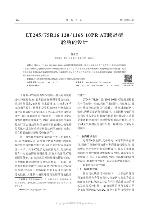
LT245/75R16 120/116S 10PR AT越野型轮胎的设计蔡莹莹[佳通轮胎(中国)研发中心,安徽合肥 230601]摘要:介绍LT245/75R16 120/116S 10PR AT越野型轮胎的设计。
通过对胎面花纹进行优化设计,并重点对胎面钢片数量、沟槽深度进行搭配设计以及调整沟槽的形态和尺寸,使其兼顾夏季越野轮胎和雪地越野轮胎的综合性能。
轮胎模拟仿真分析和成品性能试验结果表明,本设计轮胎不仅具有优异的雪地性能,还具有卓越的普通路面干湿地操控性能和非铺装路面的爬坡越野性能。
关键词:全地形越野型轮胎;结构设计;雪地牵引性能;成品轮胎性能中图分类号:TQ336.1;U463.341+.2 文章编号:1006-8171(2023)07-0406-05文献标志码:A DOI:10.12135/j.issn.1006-8171.2023.07.0406全地形(AT)越野型SUV轮胎一般具有高速通过性和越野爬坡、恶劣路面抗撕裂等综合性能。
针对市场需求,如西藏、西北路况,山区较多,冬季山路积雪较多,越野车型及轮胎的客户越来越多地要求其适配的AT轮胎不但要具有较强的越野通过性,而且能兼顾冬季气候多变、山地较多且常有薄雪的越野市场需求[1]。
因此,越来越多的汽车及轮胎厂家会通过增加雪地抓着性能测试,使轮胎的雪地牵引及制动抓着指数达到雪地标识标准,并在轮胎胎侧上增加雪峰标识[2-3]。
由于冰雪地性能的影响因素主要有胎面胶配方、花纹沟槽设计、花纹钢片数量及深度,因此提高轮胎的冰雪地性能主要是从胎面胶配方和花纹设计入手。
对于AT轮胎的胎面胶配方,其胶料应具有一定的越野抗撕裂性能,因此本设计的AT轮胎既要保证其正常路况的操控越野抗撕裂性能,又要能提高轮胎的冰雪地抓着性能,不能单一地只调整胎面胶配方,而必须要攻破胎面花纹设计的瓶颈,使其既不会影响轮胎的干湿地及越野路况的性能,又能较大幅度地提高轮胎的雪地抓着性能[4-6]。
汽车轮胎参数和配置手册说明书

(January 2004)Heavy Duty Application ListJuly 2010*May have either H-140 or H-172 carrier; check carrier to determine correct NoSPIN differential. #Produced with different axle shafts: count splines to determine correct NoSPIN differential.(1) 2xx, 3xx, and 4xx Models = NoSPIN / Detroit Locker brand automatic locking differential. The new “IMPROVED Detroit Locker”, indicated by an “SL” in the model number (225SL-58B) provides smooth and quieter operation in the drive-coast mode. A dampening device has been inserted into the inboard end of each side gear.A “letter” after the model indicates that a 2-piece support case assembly is supplied by Eaton with the differential. All other models (no letter) fit the 2-piece differential case supplied by the axle/vehicle maker. To install a NoSPIN differential model supplies without its own case in an axle which was originally supplied with Powr-Lok, Trac-Lok, Traction Equalizer or other locking or limited-slip differential, it will also be necessary to use the axle maker’s conventional differential support case.Bolts, bearings, shims and gaskets are not supplied by Eaton.(2) The axle shaft diameter is the “major diameter” measured over the splines at the outer end of the shaft.(3) Use 225S-18 assembly if two-piece case, use 225S-58A, B, C, D assembly if a one-piece case.(4) Model 350S-85 required for conventional differential case, while Model 350S-67 required with special 113304 and 113305 differential case.(5) If replacing conventional differential, modification of differential case is required. Call Eaton.(6) Requires Eaton 113304 and 113305 differential case.(7) A conventional 1640 differential case assembly, Clark part number 126952, must be used with 306S-46 differentialassembly, as it cannot be retrofitted into the case assembly with needle bearings.NOTESSeveral medium and heavy-duty axles were supplied with two or three axle shafts from time to time. This accounts for the listing of various NoSPIN differential models, with the latest listed first. Modification of our differentials of any kind may void your Limited warranty. Please refer to Eaton’s Limited Warranty on the back of Owner’s Manuals for complete guidelines. While this model list is believed to be accurate, we cannot guarantee there are no errors or omissions of the data. Customer is responsible to identify the correct Eaton differential for his particular application. NoSPIN, Detroit Locker, Truetrac and Suretrac are registered trademarks and Detroit LSD is a trademark of Eaton. Powr-Lok and Trac-Lok are trademarks of Dana Corporation. Traction Equalizer is a trademark of Meritor Automotive, Inc.。
GitiComfort220产品介绍

国产品牌 奇瑞
一汽
车型 A1 QQ6 QQ3 优翼 夏利2000 雅酷
夏利
威乐 威姿
PDF 文件使用 "pdfFactory Pro" 试用版本创建
原配规格
175/60R14 175/60R14 155/65R13 185/70R14 175/65R14 175/65R14 165/70R13 175/65R14 175/65R14 175/65R14
原配规格 165/70R14 175/65R14 175/70R14 175/70R14 175/65R14 175/60R13 165/70R14
负荷速度 81H 82H 84T 84T 82H 77H 81H
佳通舒适220产品 适配车型
日韩品牌 本田 丰田 铃木 马自达 起亚 现代
车型 飞度 思迪 威驰 羚羊 北斗星 马自达2
PDF 文件使用 "pdfFactory Pro" 试用版本创建
佳通舒适220产品 适配车型
欧美品牌 大众
菲亚特
福特 雪佛兰 雪铁龙
车型 POLO 派力奥 西耶那 周末风 嘉年华 乐驰 富康
PDF 文件使用 "pdfFactory Pro" 试用版本创建
240km/h 20min
69.5H 34H
GB
220
GB
220
高速试验
耐久试验
试验地点:佳通轮胎(中国)研发中心 试验项目:175/70R14高速、耐久试验 试验条件: 500Kg标准负载
佳通舒适220产品 为满足都市贵族小轿车需求而开发
轮辋
规格
开发
2010年 轮胎需求
155/65R13
佳通轮胎条码一体化应用
佳通轮胎条码一体化应用
佚名
【期刊名称】《《现代制造》》
【年(卷),期】2012(000)020
【摘要】佳通轮胎引入条码技术进行产品全生命周期追溯管理,以条码为主线贯穿原材料、取样、生产线控制、先进先出、信息发布、成品检验、设备报修维修、仓储管理到服务三包管理过程。
【总页数】1页(P13-13)
【正文语种】中文
【中图分类】TP391.44
【相关文献】
1.条码技术在制造企业物流一体化系统中的应用 [J], 杜娟;张李义
2.浅析检验信息系统的条码应用方案——打印条码和预条码 [J], 张璟n;王勇;吴学工
3.《电子商务商品条码应用指南》(一)网上商城商品条码应用 [J],
4.佳通轮胎全球一体化协同研发模式分析 [J], 苏博; 吴师通
5.佳通轮胎全球一体化协同研发模式分析 [J], 苏博; 吴师通
因版权原因,仅展示原文概要,查看原文内容请购买。
- 1、下载文档前请自行甄别文档内容的完整性,平台不提供额外的编辑、内容补充、找答案等附加服务。
- 2、"仅部分预览"的文档,不可在线预览部分如存在完整性等问题,可反馈申请退款(可完整预览的文档不适用该条件!)。
- 3、如文档侵犯您的权益,请联系客服反馈,我们会尽快为您处理(人工客服工作时间:9:00-18:30)。
强力尼龙斜交轮胎佳通轮胎产品手册
2010
斜交胎细分市场
卡客车轮胎
R17
L05R18
G212
TR120
R17
公路型
TR120
纵向曲折的胎面花纹设计加强的胎体结构设计加宽的轮胎冠宽设计
提高轮胎的抗沟裂性能提高轮胎综合性能提高轮胎耐磨性能
注: SUPER 表示加强层级。
注 :* 表示即将上市。
R18
公路型
11.00-2018PR 153/148F 8.0 3650/3150910/84016.012.00-20
18PR
154/150
F
8.5
3730/3270
810/740
16.9
10.00-2016PR 146/142G 7.5 3000/2630810/74021.411.00-2018PR 153/148F 8.0 3650/3150910/84022.312.00-20
18PR
154/150
F
8.5
3730/3270
810/740
23.3
强力尼龙斜交轮胎
卡车轮胎
C08TC160
TC161
G218
G216
工矿型
G218
技术特点
优势
采用坏路专用胎面配方
提高胎面耐刺扎、耐切割、耐撕裂性能
注:*
表示即将上市。
规格
层级
负荷指数单胎/双胎
速度级别
标准轮辋
额定负荷(kg) 单胎/双胎额定气压(kPa)
单胎/双胎
沟深(mm)
9.00-20 *16PR 145/140B 7.0 2900/2500880/81022.010.00-20 *18PR 150/145B 7.5 3350/2900910/84025.011.00-20 *18PR 153/148B 8.0 3650/3150910/84027.012.00-20 *
20PR
156/151
B
8.5
4000/3450
880/810
28.5
工矿型
强力尼龙斜交轮胎
10.00-2016PR 146/142J 7.5 3000/2630810/74017.611.00-2018PR 153/148F 8.0 3650/3150910/84018.112.00-20
18PR
154/150
F
8.5
3730/3270
810/740
18.8
G216
强力尼龙斜交轮胎
7.50-16 LT 14PR
SUPER 122/118L 6.00G 1500/1320730/73017.48.25-16 LT
16PR
128/124
L
6.50H
1800/1600
730/730
21.5
注: SUPER 表示加强层级。
工矿型
技术特点
优势
采用坏路专用胎面配方
提高胎面耐刺扎、耐切割、耐撕裂性能
注:*表示即将上市;
SUPER
表示加强层级。
规格
层级
负荷指数单胎/双胎
速度级别
标准轮辋
额定负荷(kg) 单胎/双胎额定气压(kPa)
单胎/双胎
沟深(mm)
6.50-16 LT *12PR 110/105B 5.50F 1060/925630/63014.0
7.00-16 LT *14PR 118/114B 5.50F 1320/1180730/73016.0 7.50-16 LT 14PR SUPER 122/118B 6.00G 1500/1320730/73017.6
8.25-16 LT
16PR
128/124
B
6.50H
1800/1600
730/730
19.0
工矿型
强力尼龙斜交轮胎
速度级别和负荷指数对应表
3、轮胎的拆装
2、轮胎的保养
轮胎日常使用常识
1、轮胎的充气。
